WO2022196487A1 - 霧化装置 - Google Patents
霧化装置 Download PDFInfo
- Publication number
- WO2022196487A1 WO2022196487A1 PCT/JP2022/010273 JP2022010273W WO2022196487A1 WO 2022196487 A1 WO2022196487 A1 WO 2022196487A1 JP 2022010273 W JP2022010273 W JP 2022010273W WO 2022196487 A1 WO2022196487 A1 WO 2022196487A1
- Authority
- WO
- WIPO (PCT)
- Prior art keywords
- liquid column
- plate
- duct
- air
- ultrasonic
- Prior art date
- Legal status (The legal status is an assumption and is not a legal conclusion. Google has not performed a legal analysis and makes no representation as to the accuracy of the status listed.)
- Ceased
Links
Images


Classifications
-
- B—PERFORMING OPERATIONS; TRANSPORTING
- B05—SPRAYING OR ATOMISING IN GENERAL; APPLYING FLUENT MATERIALS TO SURFACES, IN GENERAL
- B05B—SPRAYING APPARATUS; ATOMISING APPARATUS; NOZZLES
- B05B17/00—Apparatus for spraying or atomising liquids or other fluent materials, not covered by the preceding groups
- B05B17/04—Apparatus for spraying or atomising liquids or other fluent materials, not covered by the preceding groups operating with special methods
- B05B17/06—Apparatus for spraying or atomising liquids or other fluent materials, not covered by the preceding groups operating with special methods using ultrasonic or other kinds of vibrations
- B05B17/0607—Apparatus for spraying or atomising liquids or other fluent materials, not covered by the preceding groups operating with special methods using ultrasonic or other kinds of vibrations generated by electrical means, e.g. piezoelectric transducers
- B05B17/0615—Apparatus for spraying or atomising liquids or other fluent materials, not covered by the preceding groups operating with special methods using ultrasonic or other kinds of vibrations generated by electrical means, e.g. piezoelectric transducers spray being produced at the free surface of the liquid or other fluent material in a container and subjected to the vibrations
-
- B—PERFORMING OPERATIONS; TRANSPORTING
- B05—SPRAYING OR ATOMISING IN GENERAL; APPLYING FLUENT MATERIALS TO SURFACES, IN GENERAL
- B05B—SPRAYING APPARATUS; ATOMISING APPARATUS; NOZZLES
- B05B17/00—Apparatus for spraying or atomising liquids or other fluent materials, not covered by the preceding groups
- B05B17/04—Apparatus for spraying or atomising liquids or other fluent materials, not covered by the preceding groups operating with special methods
- B05B17/06—Apparatus for spraying or atomising liquids or other fluent materials, not covered by the preceding groups operating with special methods using ultrasonic or other kinds of vibrations
-
- B—PERFORMING OPERATIONS; TRANSPORTING
- B05—SPRAYING OR ATOMISING IN GENERAL; APPLYING FLUENT MATERIALS TO SURFACES, IN GENERAL
- B05B—SPRAYING APPARATUS; ATOMISING APPARATUS; NOZZLES
- B05B7/00—Spraying apparatus for discharge of liquids or other fluent materials from two or more sources, e.g. of liquid and air, of powder and gas
- B05B7/24—Spraying apparatus for discharge of liquids or other fluent materials from two or more sources, e.g. of liquid and air, of powder and gas with means, e.g. a container, for supplying liquid or other fluent material to a discharge device
Definitions
- the present invention relates to an apparatus for ultrasonically vibrating a liquid to atomize it, and more particularly to an apparatus for blowing a carrier gas onto the surface of a liquid column generated by ultrasonic vibrations to atomize the liquid.
- Devices that atomize liquids with ultrasonic vibrations are required to have high atomization efficiency. This is because by increasing the atomization efficiency, power consumption can be reduced and a large amount of mist can be generated.
- Devices that make liquid mist by ultrasonic vibration are used in a variety of industrial equipment. is used. It is difficult for an atomizing device equipped with a large number of ultrasonic transducers to efficiently atomize a liquid into a mist with all the ultrasonic transducers. The amount of mist generated cannot be reliably increased in proportion to . This is because the amount of mist generated by each ultrasonic transducer is not uniform.
- a device that atomizes a liquid by ultrasonic vibration can increase the atomization efficiency by blowing a carrier gas such as air onto the surface of the liquid column generated by ultrasonic vibration. ing.
- a carrier gas such as air onto the surface of the liquid column generated by ultrasonic vibration.
- FIG. 8 an ultrasonic atomization device 800 in which a large number of ultrasonic transducers 802 are arranged, forcibly blows air into an atomization chamber 804 to blow the air onto the surface of each liquid column to produce fog.
- the amount of solution misted by the ultrasonic transducers 802 on the downstream side as viewed from the air blowing side is remarkably reduced to less than a fraction of the amount of the ultrasonic transducers 802 on the upstream side.
- the present inventor opened a spray port 905 at the upper end of the ultrasonic transducer 902, and used a cylindrical or conical horn that tapers toward the spray port 905.
- the ultrasonic atomization device 900 is provided with a cylindrical body 906 having a shape, and further, the cylindrical body 906 is provided with a spray port 907 for supplying a carrier gas from a carrier gas source to the mist sprayed from the spray port 905. developed (see Patent Document 1).
- a plurality of ultrasonic transducers 902 can efficiently atomize into mist while reducing the amount of carrier gas as compared with FIG.
- the present invention was developed for the purpose of preventing the above-mentioned adverse effects.
- One object of the present invention is to reduce the atomization efficiency of each ultrasonic vibrator while installing a plurality of ultrasonic vibrators. To provide an ultrasonic atomizer capable of suppressing , increasing the total atomization efficiency, having a simple structure, and not requiring a large number of parts.
- An ultrasonic atomization device comprises: a plurality of ultrasonic transducers for ultrasonically vibrating a solution; an atomization chamber in which the plurality of ultrasonic transducers are arranged on the same plane; A plurality of liquid columns arranged in a posture extending in the vertical direction above the ultrasonic transducer, and a section divided into an air duct and an exhaust duct by communicating with the liquid column vertically. It comprises a plate and a fan connected to the fan duct for forcing a carrier gas into the fan duct.
- the liquid column tube is placed at a position where it guides the liquid column protruding from the liquid surface due to ultrasonic vibration, and has an internal shape that guides the liquid column inside and forms a gap between the liquid column and the liquid column.
- the lower end is above the liquid surface and has a lower end opening connected to a blower duct
- the upper end has an upper end opening connected to a discharge duct.
- the carrier gas which is blown into the air duct by the blower, flows into the liquid column cylinder from the lower end opening, flows through the air blow gap, separates the mist from the surface of the liquid column, generates a mist mixed gas, and discharges the mist mixed gas into the duct. discharge to
- the carrier gas from the blower is supplied to the blast duct divided by the partition plate, and flows through the blast gap from the lower end opening of the liquid column that guides the liquid column inside, creating a mist mixture gas. , from the upper end opening to the discharge duct.
- the structure in which the carrier gas supplied from the blower to the fan duct is made to flow into the liquid column and blow air equalizes the inflow pressure at the lower end opening of each liquid column, and protrudes from the liquid surface.
- the above ultrasonic atomization device is provided with a liquid column communicating with a partition plate that divides the atomization chamber into a fan duct and a discharge duct, and the liquid column is arranged above the ultrasonic transducer. Since it has a simple structure, it can be mass-produced at low cost without requiring a large number of parts.
- an equalization plate is arranged in the air duct to equalize the carrier gas in the air duct and blow it to each liquid column cylinder.
- the atomization device with the above configuration can equalize the carrier gas and blow it to each liquid column cylinder.
- the carrier gas that is evenly blown into each liquid column can efficiently generate errors from each liquid column. This is because the carrier gas blown into the liquid column forcefully blows off the mist from the surface of the liquid column, and the relative humidity on the surface of the liquid column can be lowered to increase the atomization efficiency.
- This feature realizes the feature of being able to increase the total atomization efficiency by maintaining the atomization efficiency of each ultrasonic transducer at a high level while equipping a plurality of ultrasonic transducers. In this way, in addition to the partition plate and the liquid column cylinder, by further providing the equalization plate in the air duct, the decrease in the atomization efficiency of each ultrasonic transducer is further suppressed, and the total atomization efficiency can be raised.
- the equalization plate is provided with a perforated plate having a plurality of air blow holes.
- the liquid column vertically penetrates the equalizing plate, and the carrier gas flowing into the air duct passes through the air blowing hole of the equalizing plate, flows into the liquid column, and is blown to the surface of the liquid column. be.
- the carrier gas passes through each of the air blowing holes from the top to the bottom of the equalizing plate, and the carrier gas can be evenly blown to each of the liquid columns vertically penetrating the equalizing plate. It is possible to suppress the deterioration of the atomization efficiency of the ultrasonic vibrator and increase the total atomization efficiency.
- the lower end opening of the liquid column can be brought close to the liquid surface while the equalizing plate is kept away from the liquid surface.
- the equalization plate is provided with a punching plate having a plurality of air blow holes.
- a punching plate divides the air duct into an inflow side air duct and a discharge side air duct.
- the punching plate divides the air duct into the inflow side and the discharge side, and allows the carrier gas to pass through with a predetermined passage resistance, thereby generating a difference in air pressure and discharging from the inflow side air duct.
- the punching plate is provided with a large number of air blowing holes so that the carrier gas can pass through, and an easily processed and inexpensive member such as punching metal can be used.
- the equalization plate is provided with a split plate formed by splitting the air duct into a plurality of split ducts in multiple vertical stages. A plurality of split ducts splits and blows the carrier gas supplied to the blower duct to each liquid column.
- the carrier gas supplied from the blower to the blower duct is made to flow evenly into each of the liquid column cylinders while preventing unevenness from occurring in the plurality of divided ducts.
- the carrier gas can be blown evenly into the gap formed between the liquid column protruding from the liquid surface and the atomization efficiency of each ultrasonic transducer. It is possible to increase the total atomization efficiency by increasing it.
- An ultrasonic atomization device further comprises a discharge plate arranged inside the discharge duct.
- the discharge plate has a plurality of air holes through which the mist mixture gas passes from the bottom to the top, and the mist mixture gas discharged from the upper end opening of the liquid column cylinder passes through the air blow holes of the discharge plate and is exhausted to the outside. be done.
- the air pressure in the discharge duct on the inflow side on the lower side of the discharge plate is made higher than the air pressure on the upper side of the discharge plate due to the predetermined passage resistance of the mist mixed gas passing through the plurality of air blowing holes of the discharge plate.
- the carrier gas can be evenly blown to each liquid column cylinder.
- the carrier gas is evenly supplied from the inflow side, and the mist mixed gas is evenly discharged from the discharge side, so that each liquid column is stabilized more stably.
- the carrier gas can be blown evenly into the cylinder. Therefore, by providing the partition plate, the liquid column cylinder, the equalization plate, and the discharge plate, it is possible to further suppress the decrease in the atomization efficiency of each ultrasonic transducer and increase the total atomization efficiency.
- Another embodiment of the ultrasonic atomization device of the present invention is a punching plate in which the discharge plate is provided with a plurality of air blow holes.
- the punching plate is provided with a large number of air holes so that the mist mixed gas can pass through, is an easily processed and inexpensive member, and is suitable as a discharge plate.
- the discharge plate allows the mist mixed gas to pass through with a predetermined passage resistance, so that the carrier gas can be uniformly blown to each liquid column.
- a liquid column is connected to a partition plate.
- the liquid column cylinder can be easily positioned on the partition plate and arranged at an appropriate position, and the uniformized carrier gas is blown into the blowing gap to increase the atomization efficiency of each ultrasonic transducer. It is possible to increase the total atomization efficiency by increasing it.
- the liquid column cylinder is connected to the partition plate that divides the air duct and the discharge duct in the atomization chamber, and the simple structure in which the liquid column cylinder is arranged above the ultrasonic transducer does not require a large number of parts. It is easy to manufacture and can be mass-produced at low cost.
- FIG. 1 is a schematic configuration diagram showing an ultrasonic atomization device according to one embodiment of the present invention.
- FIG. 2 is an enlarged cross-sectional view of the essential part of the ultrasonic atomization device of FIG. 3 is a schematic perspective view showing a partition plate, an equalization plate, and a discharge plate of the ultrasonic atomization device of FIG. 1.
- FIG. FIG. 4 is a schematic configuration diagram showing an ultrasonic atomization device according to another embodiment of the present invention.
- 5 is a schematic perspective view showing a partition plate, an equalization plate, and a discharge plate of the ultrasonic atomizer of FIG. 4.
- FIG. FIG. 6 is a schematic configuration diagram showing an ultrasonic atomization device according to another embodiment of the present invention.
- FIG. 1 is a schematic configuration diagram showing an ultrasonic atomization device according to one embodiment of the present invention.
- FIG. 2 is an enlarged cross-sectional view of the essential part of the ultrasonic atomization device of FIG. 3 is
- FIG. 7 is a schematic configuration diagram showing an ultrasonic atomization device according to another embodiment of the present invention.
- FIG. 8 is a schematic configuration diagram showing a state in which a conventional ultrasonic separator atomizes a solution into mist with a large number of ultrasonic oscillators.
- FIG. 9 is a schematic cross-sectional view showing a state in which another conventional ultrasonic separator atomizes a solution into mist with a large number of ultrasonic transducers.
- 10 is an enlarged cross-sectional front view showing a cylinder of the ultrasonic separation device shown in FIG. 9.
- FIG. 9 is a schematic configuration diagram showing an ultrasonic atomization device according to another embodiment of the present invention.
- the ultrasonic atomization device of the present invention uses ultrasonic vibration to disperse a liquid into a fine mist in a carrier gas.
- Apparatuses for atomizing solutions are suitable for separating and concentrating water from solutions, or for separating high-purity water from solutions. It is important for the device used for this purpose to increase the atomization efficiency to increase the energy efficiency, and to reduce the particle size of the mist to increase the atomization efficiency of the fine mist.
- Blowing a carrier gas such as air onto the surface of the liquid column protruding from the liquid surface by ultrasonic vibration is effective in improving atomization efficiency.
- the fresh air blown on the surface of the liquid column blows off the mist dispersed in the air from the interface between the liquid and the gas with the energy of ultrasonic vibration, separating it from the surface of the liquid column and lowering the relative humidity of the surface of the liquid column. This is because the environment in which nano-sized fine mist is generated can be improved.
- An increase in humidity on the surface of the liquid column causes a decrease in atomization efficiency, and as the relative humidity approaches 100%, the atomization efficiency of nano-sized mist decreases. It can be considered from the principle of generation of nano-sized mist.
- the nano-sized mist is generated by evaporating the mist separated from the surface of the liquid column to form water vapor, cooling the water vapor to liquefy, and condensing the liquefied water droplets to form fine mist. Therefore, in order to increase the atomization efficiency of nano-sized mist, an environment in which the mist separated from the surface of the liquid column is vaporized into water vapor, and the vaporized water vapor is cooled and liquefied, and the liquefied fine water is required. An environment that aggregates to form a nano-sized mist is required. The ultrasonic vibration separates the micron-sized mist, which is larger than the nano-sized particles, from the liquid column.
- micron-sized mist In order to turn the micron-sized mist separated from the liquid column into nano-sized mist, it is necessary to evaporate the micron-sized mist into water vapor, liquefy the water vapor, and further condense it into nano-sized mist.
- the micron-sized mist is vaporized by the carrier gas forcedly blown to the surface of the liquid column to become water vapor. Since the micron-sized mist has a large surface area, the relative humidity of the carrier gas can be lowered so that it can quickly vaporize into water vapor.
- the carrier gas obtained by vaporizing the micron-sized mist is cooled by the vaporization heat of the mist, liquefies the water vapor, and aggregates to form nano-sized mist.
- Nano-sized mist is generated by vaporizing micron-sized mist, so it has a high concentration of components that are easy to vaporize. Pure water can be separated. In addition, the concentration of alcohol can be increased by recovering the alcohol water as a nano-sized mist.
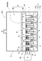
- FIG. 1 is a schematic configuration diagram of an ultrasonic atomization device 1 according to Embodiment 1
- FIG. 2 is an enlarged cross-sectional view of a main part of the ultrasonic atomization device 1 shown in FIG. 1
- FIG. 1 shows a schematic perspective view showing a partition plate 15, an equalization plate 17, and a discharge plate 20 of the ultrasonic atomization device 1 of No. 1, respectively.
- FIG. 1 is a schematic configuration diagram of an ultrasonic atomization device 1 according to Embodiment 1 of the present invention. Generates a large amount of mist with high atomization efficiency.
- This ultrasonic atomization device 1 has a plurality of ultrasonic transducers 2 for ultrasonically vibrating a solution arranged in the same plane in an atomization chamber 4 .
- a liquid column cylinder 9 is disposed above the ultrasonic transducer 2 and in a posture extending in the vertical direction.
- a partition plate 15 is arranged so as to vertically communicate with each liquid column cylinder 9 to divide the inside of the atomization chamber 4 into the fan duct 7 and the discharge duct 8 .
- a blower 25 is connected to the blower duct 7 at its discharge side, and the blower 25 forcibly blows a carrier gas such as air into the blower duct 7 . (Atomization chamber 4)
- the atomization chamber 4 shown in FIG. 1 is supplied with a liquid to be atomized, such as water or solution, at a constant liquid level 5 .
- the liquid supplied to the atomization chamber 4 varies depending on the application of the ultrasonic atomization device 1.
- a solution in which a solute such as salt is dissolved in water separates the water to condense the solution, and also produces a mist. It can be recovered to separate pure water from the solution, and can be used for purposes such as concentrating alcohol by ultrasonically vibrating alcoholic water.
- the atomization chamber 4 supplies the solution when the liquid level drops, for example, to maintain the liquid level at a set value.
- the liquid level in the chamber 4 is detected by a level sensor, the operation of the pump is controlled by the level sensor, and when the liquid level in the atomization chamber 4 drops, the pump is operated to keep the liquid level at the set value. be able to. (Ultrasonic transducer 2)
- the atomization chamber 4 shown in FIG. 1 has a plurality of ultrasonic transducers 2 arranged at the bottom so as to radiate ultrasonic waves upward.
- the ultrasonic oscillator 2 is fixed to the bottom of the atomization chamber 4 and arranged at a constant depth from the liquid surface 5 .
- Each ultrasonic transducer 2 is connected to an ultrasonic power supply (not shown) and excited by an alternating current of several tens of KHz to several MHz supplied from the ultrasonic power supply to ultrasonically vibrate.
- Each ultrasonic vibrator 2 is placed at the same depth and emits ultrasonic vibrations upward to protrude a liquid column 6 from the liquid surface 5 .
- the ultrasonic oscillator 2 radiates ultrasonic vibrations with a narrow radiation angle to project a liquid column 6 from the liquid surface 5 .
- the liquid inside the liquid column 6 is ultrasonically vibrated to separate the liquid from the surface in the form of a mist.
- the mist separated from the liquid column 6 is dispersed in the forcibly blown carrier gas to form a mist mixed gas.
- the liquid column cylinder 9 shown in FIGS. 1 and 2 blows a carrier gas onto the surface of the liquid column 6 arranged inside to improve the atomization efficiency.
- the liquid column cylinder 9 is disposed in a posture extending vertically above the ultrasonic transducer 2, which is a vertical posture in FIG. 1, and guides the liquid column 6 inside.
- the liquid column cylinder 9 is arranged at a position to guide the liquid column 6 protruding from the liquid surface 5 by ultrasonic vibration.
- the ultrasonic transducer 2 that emits ultrasonic vibrations directly above has a liquid column cylinder 9 arranged directly above it, and guides the liquid column 6 inside.
- the liquid column cylinder 9 has an inner cylindrical shape that forms an air blowing gap 10 between it and the liquid column 6 that is guided inside.
- the inner shape of the liquid column cylinder 9 is made larger than the outer shape of the liquid column 6 to form an air blow gap 10 between the liquid column 6 and the liquid column 6 .
- the blowing gap 10 blows the carrier gas from bottom to top to forcibly disperse the mist separated from the surface of the liquid column 6 into the carrier gas.
- the liquid column 9 may be cylindrical or rectangular, preferably cylindrical.
- the cylindrical liquid column cylinder 9 has an inner diameter of, for example, 2 cm ⁇ to 5 cm ⁇ , preferably 3 cm ⁇ to 4 cm ⁇ , and forms an air blow gap 10 with the surface of the liquid column 6 .
- the inner shape of the liquid column cylinder 9 is adjusted in consideration of the air volume of the blower 25 so as to increase the mist atomization efficiency.
- the air gap 10 is, for example, 0.4 cm to 2 cm, preferably 0.5 cm to 1.6 cm.
- the liquid column cylinder 9 shown in FIGS. 1 and 2 is open at both upper and lower ends, and has a lower end opening 11 at its lower end and an upper end opening 12 at its upper end.
- the liquid column tube 9 receives the carrier gas from the lower end opening 11 , blows the inflowing carrier gas upward through the ventilation gap 10 on the surface of the liquid column 6 , and discharges it from the upper end opening 12 .
- the lower end opening 11 of the liquid column cylinder 9 is close to the liquid surface 5 but has a gap between it and the liquid surface 5 so that the carrier gas can flow in from here. It is located above the upper end of the liquid column 9 and has a length that allows the carrier gas blown into the liquid column cylinder 9 to reach the upper end of the liquid column 6 .
- the gap between the liquid surface 5 and the bottom opening 11 is, for example, 0.4 cm to 4 cm, preferably 1 cm to 2 cm. (Compartment plate 15)
- the partition plate 15 shown in FIG. 1 has an outer peripheral edge air-tightly fixed to the inner surface of the peripheral wall of the atomization chamber 4 to partition the interior of the atomization chamber 4 into an air duct 7 and an exhaust duct 8 vertically.
- the partition plate 15 has a through hole to which the liquid column cylinder 9 is connected.
- the inner shape of the through hole is the same as the outer shape of the liquid column cylinder 9, and the upper end opening 12 of the liquid column cylinder 9 is arranged in the through hole.
- the liquid column cylinder 9 has a lower end opening 11 connected to the fan duct 7 and an upper end opening 12 connected to the discharge duct 8 .
- the partition plate 15 is a plate material made of plastic or metal, which is arranged horizontally in the lower part of the atomization chamber 4.
- a plurality of liquid column cylinders 9 are connected to the through-holes and arranged in a vertical position.
- an equalization plate 17 is arranged in a horizontal position in the air duct 7 to equalize the carrier gas supplied to the air duct 7 and blow it to each liquid column cylinder 9 .
- the equalization plate 17 shown in FIG. 1 comprises a perforated plate 17d having a plurality of perforations 18 through which the carrier gas can pass.
- the aperture ratio of the plurality of air blowing holes 18 of the perforated plate 17d can be finely adjusted by adjusting the size, number, shape, pitch, and the like of the holes.
- the perforated plate 17d can be made of metal such as stainless steel, aluminum, nickel, or plastic, and is not limited to a specific material, and an easily processed and inexpensive member, for example, a punching plate 17a such as punching metal, is suitable.
- a punching plate 17a such as punching metal
- the punching plate 17a divides the air duct 7 into an inflow side and an outflow side, with the air duct 7a on the inflow side above the punching plate 17a and the air duct 7b on the outflow side below the punching plate 17a.
- the liquid column cylinder 9 is arranged so as to vertically penetrate the punching plate 17a.
- the carrier gas forcedly blown from the blower 25 to the blowing duct 7a on the inflow side is directed to the blowing duct 7b on the discharge side as seen from the blower 25 side.
- the carrier gas is uniformly supplied to each liquid column tube 9 by uniformly blowing the air from the upstream to the downstream.
- the equalizing plate 17 (punching plate 17a) shown in FIG. 1 is arranged in a horizontal posture in the middle of the upper and lower sides of the air duct 7, preferably in the substantially central part, so that the air duct 7 is divided into the air duct 7a on the inflow side and the air duct 7a on the discharge side. It is divided into upper and lower air ducts 7b.
- the punching plate 17a allows the carrier gas to pass through the blowing holes 18 having passage resistance, and blows the carrier gas supplied from the blower 25 from the blowing duct 7a on the inflow side to the blowing duct 7b on the discharge side to separate each liquid.
- the carrier gas is uniformized and blown to the cylinder 9.
- the air duct 7 a on the inflow side is connected to a carrier gas supply port 7 c and is supplied with the carrier gas from the blower 25 .
- the punching plate 17a permeates the supplied carrier gas through the air blowing holes 18 from top to bottom, and blows the air from the air blowing duct 7a on the inflow side to the air blowing duct 7b on the discharge side.
- the enlarged sectional view of the waist in FIG. 2 shows the area where the carrier gas passes through the equalizing plate 17 (punching plate 17a).
- the air pressure in the air duct 7a on the inflow side is higher than that in the air duct 7b on the discharge side due to the pressure loss caused by the passage resistance of the carrier gas passing through the air blast holes 18.
- the equalized carrier gas is allowed to pass through, and the carrier gas is equalized and blown to each liquid column cylinder 9 .
- the equalization plate 17 holds each liquid column cylinder 9 in a vertically penetrating posture.
- Each liquid column cylinder 9 receives the carrier gas from the lower end opening 11 in the blower duct 7b on the discharge side.
- the carrier gas that has passed through the nearby air blowing hole 18 flows into the inside from the lower end opening 11, and is evenly blown to the surface of the liquid column 6 generated inside, thereby improving the atomization efficiency.
- the ultrasonic atomization device 1 capable of equalizing the carrier gas by the equalization plate 17 and forcibly blowing air to each liquid column cylinder 9 can be obtained by increasing the number of ultrasonic transducers 2 provided in the atomization chamber 4. At the same time, the liquid can be efficiently atomized by each ultrasonic transducer 2, and the total atomization amount can be increased.
- the atomization device using the punching plate 17a as the equalizing plate 17 has a simple structure, uses inexpensive punching metal, and can increase the total amount of atomization with a large number of ultrasonic transducers 2. FIG.
- the punching plate 17a of the equalizing plate 17 has an opening ratio of the blowing hole 18 excluding the opening of the liquid column cylinder 9, for example, 10% to 80%, preferably 15% to 70%, more preferably 20 to 50%. and
- the inner diameter of the blow hole 18 of the punching plate 17a is, for example, 1 mm to 10 mm, preferably 3 mm to 8 mm.
- the pitch of the blow holes 18 is, for example, 0.2 cm to 2 cm, preferably 0.5 cm to 1 cm.
- the ultrasonic atomization device 1 shown in FIG. 1 further includes a discharge plate 20.
- the discharge plate 20 is arranged in a horizontal posture between the upper and lower sides of the discharge duct 8, and vertically divides the inside of the discharge duct 8 into an inflow side discharge duct 8a and a discharge side discharge duct 8b.
- the discharge plate 20 allows the carrier gas to pass through the air blow holes 21 having passage resistance, and blows the mist mixed gas supplied from the liquid column cylinder 9 from the discharge duct 8a on the inflow side to the discharge duct 8b on the discharge side. Exhaust to the outside.
- the discharge duct 8a on the inflow side is connected to the upper end opening 12 of the liquid column 9 and supplies the carrier gas supplied from the liquid column 9 to the discharge duct 8b on the discharge side.
- the discharge plate 20 shown in FIG. 2 has air pressure in the discharge duct 8a on the inflow side that is higher than that in the discharge duct 8b on the discharge side due to the passage resistance of the carrier gas passing through the air blow holes 21, and the air pressure in each air blow hole is increased from bottom to top.
- the carrier gas is evenly passed through 21 and exhausted to the outside. By equalizing the pressure at the upper end opening 12 on the discharge side of each liquid column 9 , the carrier gas is evenly blown to each liquid column 9 .
- the discharge plate 20 shown in Figs. 1 to 3 uses a punching plate 20a having a plurality of blow holes 21.
- a punching plate 20a for example, an easily processed and inexpensive member such as punching metal is suitable.
- the discharge plate 20 allows the mist mixed gas to pass through the blowing holes 21 with a predetermined passage resistance, thereby blowing the carrier gas uniformly to each liquid column cylinder 9 .
- FIGS. 1 to 3 by providing a difference in air pressure between the blower duct 7 and the discharge duct 8, air can be blown uniformly from the high air pressure side to the low air pressure side. , the carrier gas can be evenly blown to each of the liquid column tubes 9 .
- the aperture ratio of the discharge plate 20 can be the same as that of the equalization plate 17 . Different aperture ratios can also be used. It is preferable that the aperture ratio of the discharge plate 20 is smaller than that of the equalization plate 17 .
- the equalization plate 17 provides a difference in air pressure between the inflow side air duct 7a and the discharge side air duct 7b in the air duct 7, and the discharge plate 20 provides an inflow side discharge duct 8a and the discharge side air pressure in the discharge duct 8. This is because it is possible to provide a difference in the air pressure of the exhaust duct 8b, and further to provide a difference in the air pressure between the blower duct 7 and the exhaust duct 8.
- the discharge plate 20 makes the air pressure in the discharge duct 8a on the inflow side higher than the air pressure in the discharge duct 8b on the discharge side by allowing the mist mixed gas to pass through the blowing hole 21 with a predetermined passage resistance in the discharge duct 8.
- the carrier gas whose air pressure is increased in the air blow duct 7a on the inflow side can smoothly flow into the air blow duct 7b on the discharge side.
- the aperture ratio of the discharge plate 20 is, for example, 10% to 80%, preferably 15% to 70%, more preferably 20% to 50%.
- the inner diameter of the blowing hole 21 of the discharge plate 20 is, for example, 1 mm to 10 mm, preferably 3 mm to 8 mm.
- the pitch of the blow holes 21 is, for example, 0.2 cm to 2 cm, preferably 0.5 cm to 1 cm.
- the discharge plate 20 has the effect of being able to distribute the carrier gas evenly to the respective liquid columns 9 .
- the discharge plate 20 equalizes the pressure on the discharge side of each liquid column 9, thereby equalizing the flow rate of the carrier gas passing through each liquid column 9. Therefore, the equalization plate 17 and the discharge plate 20 , the carrier gas is blown evenly through each liquid column tube 9, and the mist can be efficiently separated from the surface of the liquid column in each liquid column tube 9. Therefore, the amount of mist generated can be increased in proportion to the number of ultrasonic transducers 2, and a large number of ultrasonic transducers 2 can be provided to increase the amount of mist generated. (Blower 25)
- the blower 25 shown in FIG. 1 forcibly blows the carrier gas into the blower duct 7 .
- the air blower 25 forcibly blows the carrier gas to each liquid column tube 9 through the air duct 7 to efficiently separate the mist from the surface of the liquid column 6 guided to each liquid column tube 9 .
- the air volume and pressure at which the air blower 25 forcibly blows the carrier gas are set so that the carrier gas can be forcibly blown to each liquid column 9 and the mist can be separated most efficiently.
- the blower 25 can heat the carrier gas or cool it before blowing.
- the ultrasonic atomization device 1 in which the air blower 25 heats the air and blows it to each liquid column cylinder 9 can increase the mist atomization efficiency.
- An atomization device that cools air and forcibly blows air to each liquid column cylinder 9 is suitable for atomization of a liquid that is heated and deteriorated.
- the atomization chamber 4 has a carrier gas supply port 7c connected to a blower 25 opened in the peripheral wall on the left side in FIG.
- the supply port 7c is connected to the blower duct 7 to forcibly blow the carrier gas. Since liquid is stored in the lower part of the atomization chamber 4, the supply port 7c is opened at a position higher than the liquid level so that the liquid does not flow into the supply port 7c.
- FIG. 4 is a schematic configuration diagram of an ultrasonic atomization device 201 according to Embodiment 2
- FIG. 6 is a schematic configuration diagram of an ultrasonic atomization device 301 according to Embodiment 3
- FIG. 7 is a schematic configuration diagram of an ultrasonic atomization device 401 according to Embodiment 4. .
- the equalization plate 17 can also have the structure shown in FIGS.
- the equalization plate 17 is a punching plate 17a having a large number of air blow holes 18.
- the equalizing plate 17 can also be provided with a dividing plate 17b.
- the dividing plate 17b is arranged horizontally in the air duct 7 and divides the air duct 7 into a plurality of divided ducts 7d.
- the ultrasonic atomization devices 201, 301, and 401 shown in these figures are provided with divided plates 17b arranged in multiple stages to provide upper and lower multiple stages of divided ducts 7d.
- the equalization plate 17 of the ultrasonic atomization device 201 according to Embodiment 2 shown in FIGS. 4 and 5 includes a punching plate 17a and a split plate 17b.
- a dividing plate 17b shown in the figure is placed in the air duct 7 in a horizontal position to divide the air duct 7a on the inflow side into a plurality of divided ducts 7d.
- the ultrasonic atomization device 201 of FIG. 4 divides the air duct 7 into the inflow side air duct 7a and the discharge side air duct 7b by the equalizing plate 17 of the punching plate 17a, and further divides the inflow side air duct 7b into 7a is divided into upper and lower multistage divided ducts 7d by a plurality of dividing plates 17b.
- the upper and lower multistage split ducts 7d have an inflow side edge arranged near the carrier gas supply port 7c and an outflow side edge arranged front and back in the blowing direction so that the carrier gas is supplied to each liquid column cylinder. Equalize to 9 and blow.
- the atomization device 201 divides the carrier gas supplied from the blower 25 to the inflow-side blower duct 7a into a plurality of divided ducts 7d, equalizes the carrier gas, and blows it to each of the liquid columns 9.
- the dividing plate 17b bends downward the tip edge of the horizontal plate portion 17c arranged in a horizontal posture to blow the carrier gas to the punching plate 17a.
- the divided plate 17b is arranged such that the leading end edge of the upper stage is located downstream of the leading edge of the lower stage in the air blowing direction, and the divided duct 17b of the upper stage is longer in the air blowing direction than the divided duct 17b of the lower stage, so that the carrier gas is separated from each other.
- the air is uniformly blown to the liquid column cylinder 9 of .
- Each split plate 17b is provided with a through hole for the liquid column 9, and the liquid column 9 is inserted through the through hole.
- the air duct 7a on the inflow side is partitioned into three stages of divided ducts 7d by two divided plates 17b, and the carrier gas is evenly distributed to the punching plates 17a by each of the divided ducts 7d. to blow air.
- the atomization device 201 of FIG. 4 has two dividing plates 17b arranged in the inflow-side air duct 7a, and divides the inflow-side air duct 7a into the upper inflow-side air duct 7a (dividing plate 15).
- the divided duct 7d between the upper divided plate 17b, the divided duct 7d between the upper and lower divided plates 17b, and the divided duct 7d between the lower divided plate 17b and the punching plate 17a. is doing.
- the carrier gas is blown to the liquid column cylinders 9 arranged in six rows in the blowing direction by the divided ducts 7d having three upper and lower stages.
- the ultrasonic atomization device 201 having this structure divides the carrier gas supplied from the blower 25 into three divided ducts 7d, and can evenly blow the carrier gas to each liquid column cylinder 9 via the punching plate 17a.
- the atomization device 201 of FIG. 4 blows air to two rows of liquid columns 9 through one split duct 7d. It is also possible to adopt a structure in which a carrier gas is blown to 9 .
- An ultrasonic atomization device 301 according to Embodiment 3 shown in FIG. 6 blows a carrier gas to a row of liquid column cylinders 9 with one split duct 17b.
- the inflow side fan duct 7a is divided by the dividing plate 15b into the number of the liquid columns 9 arranged in the blowing direction, and the carrier gas is supplied to each of the liquid columns 9 by each of the divided ducts 7d. to fan. Therefore, in the atomization device 301 arranged in six rows in the air blowing direction shown in FIG. Then, air is blown to each liquid column cylinder 9 from each split duct 7d.
- the equalization plate 17 is configured only by the split plate 17b without providing the punching plate 17a.
- the lower edge of the bent portion formed by bending downward provided at the leading end edge is placed in the liquid so that the carrier gas in the divided duct 7d does not pass through the punching plate 17a.
- the air is evenly blown to the liquid column cylinder 9 .
- This atomization device 401 can equalize the carrier gas by the equalization plate 17 consisting of only the split plate 17b and blow air to each liquid column cylinder 9, so that the carrier gas can be equalized with a simple structure without the punching plate 17a. , and can be blown to the liquid column cylinder 9.
- the present invention can be suitably applied to an ultrasonic atomization device equipped with a plurality of ultrasonic transducers and capable of suppressing a decrease in the atomization efficiency of each ultrasonic transducer and increasing the total atomization efficiency. .
- Reference Signs List 1 201, 301, 401, 800, 900 Ultrasonic atomization device 2, 802, 902 Ultrasonic vibrator 4, 804, 904 Atomization chamber 5 Liquid surface 6 Liquid column 7 Fan duct 7a Inflow-side air duct 7b Discharge-side air duct 7c Supply port 7d Divided duct 8 Discharge duct 8a Inflow-side discharge duct 8b Discharge-side discharge duct 9 Liquid column cylinder 10 Blow gap 11 Lower end Opening 12 Upper end opening 15 Partitioning plate 17 Equalizing plate 17a Punching plate 17b Divided plate 17c Horizontal plate 17d Perforated plate 18 Blow hole 20 Discharge plate 20a Punching plate 21 Blow hole 25 ... Air blower 905 ... Spray port 906 ... Cylindrical body 907 ... Fumarole
Landscapes
- Special Spraying Apparatus (AREA)
Priority Applications (1)
| Application Number | Priority Date | Filing Date | Title |
|---|---|---|---|
| JP2023507023A JPWO2022196487A1 (https=) | 2021-03-18 | 2022-03-09 |
Applications Claiming Priority (2)
| Application Number | Priority Date | Filing Date | Title |
|---|---|---|---|
| JP2021045094 | 2021-03-18 | ||
| JP2021-045094 | 2021-03-18 |
Publications (1)
| Publication Number | Publication Date |
|---|---|
| WO2022196487A1 true WO2022196487A1 (ja) | 2022-09-22 |
Family
ID=83320576
Family Applications (1)
| Application Number | Title | Priority Date | Filing Date |
|---|---|---|---|
| PCT/JP2022/010273 Ceased WO2022196487A1 (ja) | 2021-03-18 | 2022-03-09 | 霧化装置 |
Country Status (2)
| Country | Link |
|---|---|
| JP (1) | JPWO2022196487A1 (https=) |
| WO (1) | WO2022196487A1 (https=) |
Cited By (1)
| Publication number | Priority date | Publication date | Assignee | Title |
|---|---|---|---|---|
| CN117912931A (zh) * | 2024-03-19 | 2024-04-19 | 宁波华仪宁创智能科技有限公司 | 非接触样品雾化进样装置和方法 |
Citations (3)
| Publication number | Priority date | Publication date | Assignee | Title |
|---|---|---|---|---|
| JPS5826061Y2 (ja) * | 1978-06-30 | 1983-06-04 | のむら産業株式会社 | 超音波霧発生装置 |
| JPS5831227B2 (ja) * | 1978-06-30 | 1983-07-05 | のむら産業株式会社 | 超音波霧発生装置 |
| JPH0426061U (https=) * | 1990-06-28 | 1992-03-02 |
Family Cites Families (2)
| Publication number | Priority date | Publication date | Assignee | Title |
|---|---|---|---|---|
| JP2001201122A (ja) * | 2000-01-19 | 2001-07-27 | Honda Motor Co Ltd | 加湿装置 |
| JP5494902B2 (ja) * | 2006-07-05 | 2014-05-21 | ナノミストテクノロジーズ株式会社 | 溶液の超音波分離装置 |
-
2022
- 2022-03-09 WO PCT/JP2022/010273 patent/WO2022196487A1/ja not_active Ceased
- 2022-03-09 JP JP2023507023A patent/JPWO2022196487A1/ja active Pending
Patent Citations (3)
| Publication number | Priority date | Publication date | Assignee | Title |
|---|---|---|---|---|
| JPS5826061Y2 (ja) * | 1978-06-30 | 1983-06-04 | のむら産業株式会社 | 超音波霧発生装置 |
| JPS5831227B2 (ja) * | 1978-06-30 | 1983-07-05 | のむら産業株式会社 | 超音波霧発生装置 |
| JPH0426061U (https=) * | 1990-06-28 | 1992-03-02 |
Cited By (1)
| Publication number | Priority date | Publication date | Assignee | Title |
|---|---|---|---|---|
| CN117912931A (zh) * | 2024-03-19 | 2024-04-19 | 宁波华仪宁创智能科技有限公司 | 非接触样品雾化进样装置和方法 |
Also Published As
| Publication number | Publication date |
|---|---|
| JPWO2022196487A1 (https=) | 2022-09-22 |
Similar Documents
| Publication | Publication Date | Title |
|---|---|---|
| US6883724B2 (en) | Method and device for production, extraction and delivery of mist with ultrafine droplets | |
| CN100346883C (zh) | 带有倾斜孔板的喷雾器及用于其的可更换贮存器 | |
| US8979000B2 (en) | Ultrasonic atomization method and apparatus | |
| JP2005502463A5 (https=) | ||
| CA2475582A1 (en) | Ultrasonic solution separator | |
| CN114599404B (zh) | 净化系统 | |
| JP7457306B2 (ja) | 微小液滴形成装置および分析装置 | |
| CN112020371A (zh) | 净化装置 | |
| WO2006070839A1 (ja) | 溶液の超音波分離方法とこの方法に使用される超音波分離装置 | |
| JP5517025B2 (ja) | 溶液の超音波霧化機 | |
| WO2022196487A1 (ja) | 霧化装置 | |
| WO2020241150A1 (ja) | 超音波霧化装置および調湿装置 | |
| JP5084007B2 (ja) | 粒子の分離方法と分離装置 | |
| JP3789845B2 (ja) | 表面過剰液体を分離する分離装置 | |
| CN112604828A (zh) | 喷嘴及基板清洗装置 | |
| WO2023112707A1 (ja) | 超音波霧化装置 | |
| JP2005066554A5 (https=) | ||
| CN113660959B (zh) | 雾供给装置 | |
| JP7680536B2 (ja) | 試料液体霧化装置、及び分析装置 | |
| JP7830662B2 (ja) | 液体霧化装置及びそれを用いた分析装置 | |
| JP2008147149A (ja) | 水による空気負イオン発生方法及び装置 | |
| JP2006294762A (ja) | 基板処理装置 | |
| WO2024259454A1 (en) | Cartridge for stable high-output aerosol-based printing | |
| JP2016075424A (ja) | 二流体噴霧器及びこれを備えた空気調和装置の室外機 | |
| TW201519957A (zh) | 超音波二流體霧化裝置之噴頭 |
Legal Events
| Date | Code | Title | Description |
|---|---|---|---|
| 121 | Ep: the epo has been informed by wipo that ep was designated in this application |
Ref document number: 22771238 Country of ref document: EP Kind code of ref document: A1 |
|
| ENP | Entry into the national phase |
Ref document number: 2023507023 Country of ref document: JP Kind code of ref document: A |
|
| NENP | Non-entry into the national phase |
Ref country code: DE |
|
| 122 | Ep: pct application non-entry in european phase |
Ref document number: 22771238 Country of ref document: EP Kind code of ref document: A1 |