WO2022196016A1 - 情報処理装置および情報処理方法、ならびに、センシングシステム - Google Patents
情報処理装置および情報処理方法、ならびに、センシングシステム Download PDFInfo
- Publication number
- WO2022196016A1 WO2022196016A1 PCT/JP2021/047830 JP2021047830W WO2022196016A1 WO 2022196016 A1 WO2022196016 A1 WO 2022196016A1 JP 2021047830 W JP2021047830 W JP 2021047830W WO 2022196016 A1 WO2022196016 A1 WO 2022196016A1
- Authority
- WO
- WIPO (PCT)
- Prior art keywords
- unit
- information
- recognition
- point group
- image
- Prior art date
- Legal status (The legal status is an assumption and is not a legal conclusion. Google has not performed a legal analysis and makes no representation as to the accuracy of the status listed.)
- Ceased
Links
Images














Classifications
-
- G—PHYSICS
- G01—MEASURING; TESTING
- G01S—RADIO DIRECTION-FINDING; RADIO NAVIGATION; DETERMINING DISTANCE OR VELOCITY BY USE OF RADIO WAVES; LOCATING OR PRESENCE-DETECTING BY USE OF THE REFLECTION OR RERADIATION OF RADIO WAVES; ANALOGOUS ARRANGEMENTS USING OTHER WAVES
- G01S17/00—Systems using the reflection or reradiation of electromagnetic waves other than radio waves, e.g. lidar systems
- G01S17/02—Systems using the reflection of electromagnetic waves other than radio waves
- G01S17/06—Systems determining position data of a target
- G01S17/08—Systems determining position data of a target for measuring distance only
- G01S17/32—Systems determining position data of a target for measuring distance only using transmission of continuous waves, whether amplitude-, frequency-, or phase-modulated, or unmodulated
- G01S17/34—Systems determining position data of a target for measuring distance only using transmission of continuous waves, whether amplitude-, frequency-, or phase-modulated, or unmodulated using transmission of continuous, frequency-modulated waves while heterodyning the received signal, or a signal derived therefrom, with a locally-generated signal related to the contemporaneously transmitted signal
-
- G—PHYSICS
- G01—MEASURING; TESTING
- G01S—RADIO DIRECTION-FINDING; RADIO NAVIGATION; DETERMINING DISTANCE OR VELOCITY BY USE OF RADIO WAVES; LOCATING OR PRESENCE-DETECTING BY USE OF THE REFLECTION OR RERADIATION OF RADIO WAVES; ANALOGOUS ARRANGEMENTS USING OTHER WAVES
- G01S17/00—Systems using the reflection or reradiation of electromagnetic waves other than radio waves, e.g. lidar systems
- G01S17/02—Systems using the reflection of electromagnetic waves other than radio waves
- G01S17/06—Systems determining position data of a target
- G01S17/08—Systems determining position data of a target for measuring distance only
- G01S17/32—Systems determining position data of a target for measuring distance only using transmission of continuous waves, whether amplitude-, frequency-, or phase-modulated, or unmodulated
- G01S17/36—Systems determining position data of a target for measuring distance only using transmission of continuous waves, whether amplitude-, frequency-, or phase-modulated, or unmodulated with phase comparison between the received signal and the contemporaneously transmitted signal
-
- G—PHYSICS
- G01—MEASURING; TESTING
- G01S—RADIO DIRECTION-FINDING; RADIO NAVIGATION; DETERMINING DISTANCE OR VELOCITY BY USE OF RADIO WAVES; LOCATING OR PRESENCE-DETECTING BY USE OF THE REFLECTION OR RERADIATION OF RADIO WAVES; ANALOGOUS ARRANGEMENTS USING OTHER WAVES
- G01S17/00—Systems using the reflection or reradiation of electromagnetic waves other than radio waves, e.g. lidar systems
- G01S17/02—Systems using the reflection of electromagnetic waves other than radio waves
- G01S17/06—Systems determining position data of a target
- G01S17/42—Simultaneous measurement of distance and other co-ordinates
-
- G—PHYSICS
- G01—MEASURING; TESTING
- G01S—RADIO DIRECTION-FINDING; RADIO NAVIGATION; DETERMINING DISTANCE OR VELOCITY BY USE OF RADIO WAVES; LOCATING OR PRESENCE-DETECTING BY USE OF THE REFLECTION OR RERADIATION OF RADIO WAVES; ANALOGOUS ARRANGEMENTS USING OTHER WAVES
- G01S17/00—Systems using the reflection or reradiation of electromagnetic waves other than radio waves, e.g. lidar systems
- G01S17/02—Systems using the reflection of electromagnetic waves other than radio waves
- G01S17/50—Systems of measurement based on relative movement of target
- G01S17/58—Velocity or trajectory determination systems; Sense-of-movement determination systems
-
- G—PHYSICS
- G01—MEASURING; TESTING
- G01S—RADIO DIRECTION-FINDING; RADIO NAVIGATION; DETERMINING DISTANCE OR VELOCITY BY USE OF RADIO WAVES; LOCATING OR PRESENCE-DETECTING BY USE OF THE REFLECTION OR RERADIATION OF RADIO WAVES; ANALOGOUS ARRANGEMENTS USING OTHER WAVES
- G01S17/00—Systems using the reflection or reradiation of electromagnetic waves other than radio waves, e.g. lidar systems
- G01S17/88—Lidar systems specially adapted for specific applications
- G01S17/89—Lidar systems specially adapted for specific applications for mapping or imaging
-
- G—PHYSICS
- G01—MEASURING; TESTING
- G01S—RADIO DIRECTION-FINDING; RADIO NAVIGATION; DETERMINING DISTANCE OR VELOCITY BY USE OF RADIO WAVES; LOCATING OR PRESENCE-DETECTING BY USE OF THE REFLECTION OR RERADIATION OF RADIO WAVES; ANALOGOUS ARRANGEMENTS USING OTHER WAVES
- G01S7/00—Details of systems according to groups G01S13/00, G01S15/00, G01S17/00
- G01S7/48—Details of systems according to groups G01S13/00, G01S15/00, G01S17/00 of systems according to group G01S17/00
- G01S7/4802—Details of systems according to groups G01S13/00, G01S15/00, G01S17/00 of systems according to group G01S17/00 using analysis of echo signal for target characterisation; Target signature; Target cross-section
-
- G—PHYSICS
- G06—COMPUTING OR CALCULATING; COUNTING
- G06F—ELECTRIC DIGITAL DATA PROCESSING
- G06F3/00—Input arrangements for transferring data to be processed into a form capable of being handled by the computer; Output arrangements for transferring data from processing unit to output unit, e.g. interface arrangements
- G06F3/01—Input arrangements or combined input and output arrangements for interaction between user and computer
-
- G—PHYSICS
- G06—COMPUTING OR CALCULATING; COUNTING
- G06F—ELECTRIC DIGITAL DATA PROCESSING
- G06F3/00—Input arrangements for transferring data to be processed into a form capable of being handled by the computer; Output arrangements for transferring data from processing unit to output unit, e.g. interface arrangements
- G06F3/01—Input arrangements or combined input and output arrangements for interaction between user and computer
- G06F3/011—Arrangements for interaction with the human body, e.g. for user immersion in virtual reality
-
- G—PHYSICS
- G06—COMPUTING OR CALCULATING; COUNTING
- G06F—ELECTRIC DIGITAL DATA PROCESSING
- G06F3/00—Input arrangements for transferring data to be processed into a form capable of being handled by the computer; Output arrangements for transferring data from processing unit to output unit, e.g. interface arrangements
- G06F3/01—Input arrangements or combined input and output arrangements for interaction between user and computer
- G06F3/017—Gesture based interaction, e.g. based on a set of recognized hand gestures
Definitions
- the present disclosure relates to an information processing device, an information processing method, and a sensing system.
- Systems that perform input operations in response to gestures by users and movements of objects other than users detect the movements and positions of fingers, hands, arms, or objects other than humans with sensors,
- the input operation is performed with the assistance of the hand, pointer, virtual objects, and visual effects for feedback. Therefore, if the output error or processing time of the three-dimensional position sensor for detecting the movement and position of human fingers, hands, arms, and non-human objects is large, the input may cause a sense of incongruity. was there.
- Patent Document 1 discloses a technique for improving the stability and responsiveness of a user's pointing position in virtual reality by using a three-dimensional range camera and a wrist device including an inertial sensor and a transmitter attached to the human body. is disclosed.
- the user needs to wear a wrist device, and the only target input is a human pointing input that is inferred from the position of the elbow and the orientation of the forearm.
- the present disclosure provides an information processing device, an information processing method, and a sensing system capable of improving display stability and responsiveness in response to wide-ranging movements of people and non-human objects.
- the information processing device outputs a point group containing velocity information and the three-dimensional coordinates of the point group based on a received signal reflected by an object, and uses continuous frequency modulation waves.
- a recognition unit that performs recognition processing based on the point group output by the light detection and distance measurement unit, determines a designated area in a real object, and outputs three-dimensional recognition information including information indicating the determined designated area;
- a correction unit that corrects the three-dimensional coordinates of the specified region in the point group based on the three-dimensional recognition information output by the unit.
- An information processing method outputs a point group including velocity information and three-dimensional coordinates of the point group based on a received signal reflected by an object and received by a processor.
- Recognition processing is performed based on the point group output by the photodetector and distance measuring unit using continuous modulated waves to determine a designated area in the real object, and three-dimensional recognition information including information indicating the determined designated area is output.
- a recognition step and a correction step of correcting the three-dimensional coordinates of the specified region in the point group based on the three-dimensional recognition information output by the recognition step.
- a sensing system outputs a point group containing velocity information and three-dimensional coordinates of the point group based on a received signal reflected by an object, and outputs light using a continuous frequency modulated wave.
- a detection and ranging unit a recognition unit that performs recognition processing based on the point cloud to determine a designated area in a real object, and outputs three-dimensional recognition information including information indicating the determined designated area, and output by the recognition unit.
- a correction unit that corrects the three-dimensional coordinates of the specified region in the point group based on the three-dimensional recognition information that has been obtained.
- FIG. 1 is a block diagram showing an example configuration of a sensing system applicable to each embodiment of the present disclosure
- FIG. FIG. 3 is a block diagram showing an example configuration of a light detection and ranging unit applicable to each embodiment of the present disclosure
- FIG. 4 is a schematic diagram schematically showing an example of scanning of transmission light by a scanning unit
- 1 is a block diagram showing an example configuration of a sensing system according to the present disclosure
- FIG. 1 is a block diagram showing an example configuration of a sensing system according to a first embodiment
- FIG. FIG. 2 is a schematic diagram for explaining an example usage form of the sensing system according to the first embodiment
- 3 is a functional block diagram of an example for explaining functions of an application execution unit according to the first embodiment
- FIG. 5 is an example flowchart for explaining the operation of the sensing system according to the first embodiment; 7 is an example flowchart for explaining processing by the sensor unit according to the first embodiment;
- FIG. 11 is a schematic diagram for explaining an example usage form of the sensing system according to the first modification of the first embodiment;
- FIG. 11 is a schematic diagram for explaining an exemplary usage form of the sensing system according to the second modification of the first embodiment;
- FIG. 10 is a schematic diagram for explaining an exemplary usage form of the sensing system according to the second embodiment;
- FIG. 10 is a block diagram showing an example configuration of a sensing system according to a second embodiment;
- FIG. 11 is a functional block diagram of an example for explaining the functions of the glasses-type device according to the second embodiment; 9 is an example flowchart for explaining the operation of the sensing system according to the second embodiment; FIG. 10 is an example flowchart for explaining processing by a sensor unit according to the second embodiment; FIG. FIG. 11 is a block diagram showing an example configuration of a sensing system according to a modification of the second embodiment; FIG. 11 is a block diagram showing an example configuration of a sensing system according to a modification of the second embodiment; FIG. 11 is a schematic diagram for explaining an example usage form of a sensing system according to a third embodiment; FIG. 11 is a block diagram showing an example configuration of a sensing system according to a third embodiment; FIG.
- FIG. 12 is a functional block diagram of an example for explaining functions of an application execution unit according to the third embodiment;
- FIG. FIG. 11 is a flow chart of an example for explaining the operation of the sensing system according to the third embodiment;
- FIG. FIG. 11 is a flow chart of an example for explaining processing by a sensor unit according to the third embodiment;
- FIG. FIG. 11 is a block diagram showing an example configuration of a sensing system according to a fourth embodiment;
- FIG. FIG. 11 is a flow chart of an example for explaining processing by a sensor unit according to a fourth embodiment;
- the present disclosure relates to a technique suitable for displaying a virtual object in a virtual space in accordance with gestures made by humans and movements of objects other than humans.
- motion of a person or an object other than a person is detected by performing ranging on these objects.
- a ranging method for detecting motion of a person or an object other than a person which is applied to the present disclosure, will be briefly described.
- real objects humans and non-human objects that exist in the real space and are subject to distance measurement are collectively referred to as "real objects”.
- LiDAR Laser Imaging Detection and Ranging
- LiDAR is a light detection ranging device that measures the distance to a target object based on a received light signal obtained by receiving the reflected light of the laser beam irradiated to the target object.
- a scanner that scans laser light and a focal plane array type detector as a light receiving unit are used together.
- distance measurement is performed for each angle in the scanning field of view of laser light with respect to space, and data called a point group is output based on information on angles and distances.
- a point cloud is a sample of the position and spatial structure of an object included in the scanning range of the laser beam, and is generally output at regular frame times. By performing calculation processing on this point cloud data, it is possible to detect and recognize the accurate position and orientation of the target object.
- LiDAR Due to its operating principle, LiDAR's measurement results are not easily affected by external light, so it is possible to stably detect and recognize target objects, for example, even in low-illumination environments.
- Various photodetection ranging methods using LiDAR have been conventionally proposed.
- the pulse ToF (Time-of-Flight) method which combines pulse modulation and direct detection, is widespread.
- the light detection ranging method by pulse ToF using LiDAR will be referred to as dToF (direct ToF)-LiDAR as appropriate.
- dToF-LiDAR generally outputs point clouds at regular intervals (frames). By comparing the point clouds of each frame, it is possible to estimate the movement (moving speed, direction, etc.) of the object detected in the point cloud.
- FMCW-LiDAR Frequency Modulated Continuous Wave
- FMCW-LiDAR uses, as emitted laser light, chirped light in which the pulse frequency is changed, for example, linearly over time.
- FMCW-LiDAR performs distance measurement by coherent detection of a received signal obtained by synthesizing a laser beam emitted as chirped light and a reflected light of the emitted laser beam.
- FMCW-LiDAR can measure velocity at the same time as distance measurement by using the Doppler effect. Therefore, by using FMCW-LiDAR, it becomes easy to quickly grasp the position of an object with speed, such as a person or other moving object. Therefore, in the present disclosure, FMCW-LiDAR is used to detect and recognize real objects. This makes it possible to detect the movement of the real object with high responsiveness and reflect it in the display.
- FIG. 1 is a block diagram showing an example configuration of a sensing system 1 applicable to each embodiment of the present disclosure.
- the sensing system 1 includes a sensor unit 10 and an application executing section 20 that executes a predetermined operation according to an output signal output from the sensor unit 10 .
- the sensor unit 10 includes a light detection and ranging section 11 and a signal processing section 12.
- FMCW-LiDAR is applied to the photodetector and distance measuring unit 11 for performing distance measurement using laser light whose frequency is continuously modulated.
- the results of detection and distance measurement by the light detection and distance measurement unit 11 are supplied to the signal processing unit 12 as point group information having three-dimensional spatial information.
- the signal processing unit 12 performs signal processing on the detection and distance measurement results supplied from the light detection and distance measurement unit 11, and outputs information including attribute information and area information regarding the object.
- FIG. 2 is a block diagram showing an example configuration of the light detection and ranging unit 11 applicable to each embodiment of the present disclosure.
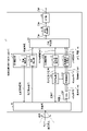
- the light detection and distance measurement unit 11 includes a scanning unit 100 , an optical transmission unit 101 , a PBS (polarization beam splitter) 102 , an optical reception unit 103 , a first control unit 110 and a second control unit 115 . , a point cloud generation unit 130 , a pre-processing unit 140 , and an interface (I/F) unit 141 .
- the first control unit 110 includes a scanning control unit 111 and an angle detection unit 112 and controls scanning by the scanning unit 100 .
- the second control unit 115 includes a transmission light control unit 116 and a reception signal processing unit 117, and controls transmission of laser light by the light detection and distance measurement unit 11 and processes reception light.
- the light transmission unit 101 includes, for example, a light source such as a laser diode for emitting laser light as transmission light, an optical system for emitting light emitted by the light source, and a laser output modulation device for driving the light source. including.
- the optical transmitter 101 causes the light source to emit light in response to an optical transmission control signal supplied from a transmission light controller 116, which will be described later, and emits chirped light whose frequency linearly changes within a predetermined frequency range over time. Emit transmission light.
- the transmitted light is sent to the scanning unit 100 and also sent to the optical receiving unit 103 as local light.
- the transmission light control unit 116 generates a signal whose frequency linearly changes (eg increases) within a predetermined frequency range over time. Such a signal whose frequency changes linearly within a predetermined frequency range over time is called a chirp signal. Based on this chirp signal, the transmission light control section 116 is a modulation synchronization timing signal that is input to the laser output modulation device included in the optical transmission section 101 . Generating an optical transmission control signal. The transmission light control unit 116 supplies the generated optical transmission control signal to the optical transmission unit 101 and the point group generation unit 130 .
- the received light received by the scanning unit 100 is polarized and separated by the PBS 102 and emitted from the PBS 102 as received light (TM) by TM polarization (p-polarization) and received light (TE) by TE polarization (s-polarization).
- Received light (TM) and received light (TE) emitted from PBS 102 are each input to optical receiver 103 .
- the light receiving unit 103 includes, for example, a light receiving unit (TM) and a light receiving unit (TE) that respectively receive (receive) received light (TM) and received light (TE) that are input, and a light receiving unit (TM) and a light receiving unit (TE) and a drive circuit for driving each.
- a light receiving section (TM) and the light receiving section (TE) for example, a pixel array in which light receiving elements such as photodiodes forming pixels are arranged in a two-dimensional lattice can be applied.
- the optical receiving unit 103 includes a synthesizing unit (TM) and a synthesizing unit (TE) for synthesizing the received light (TM) and the received light (TE) that are input, respectively, and the local light emitted from the optical transmission unit 101. further includes If the received light (TM) and the received light (TE) are the reflected light of the transmitted light from the object, the received light (TM) and the received light (TE) are respectively the distance from the object with respect to the local light. Each synthesized signal obtained by synthesizing the received light (TM) and the received light (TE) with the local light becomes a signal (beat signal) of a constant frequency.
- the optical receiver 103 supplies signals corresponding to the received light (TM) and the received light (TE) respectively to the received signal processor 117 as the received signal (TM) and the received signal (TE).
- the received signal processing unit 117 performs signal processing such as fast Fourier transform on each of the received signal (TM) and the received signal (TE) supplied from the optical receiving unit 103 .
- the received signal processing unit 117 obtains the distance to the object and the speed indicating the speed of the object, and measures measurement information (TM) including distance information and speed information indicating the distance and speed, respectively. and generate metrology information (TE).
- the received signal processing unit 117 may further obtain reflectance information indicating the reflectance of the object based on the received signal (TM) and the received signal (TE) and include it in the measurement information.
- the received signal processing unit 117 supplies the generated measurement information to the point group generation unit 130 .
- the scanning unit 100 transmits the transmission light sent from the optical transmission unit 101 at an angle according to the scanning control signal supplied from the scanning control unit 111, and receives the incident light from the angle as reception light.
- a two-axis mirror scanning device can be applied as a scanning mechanism for transmission light.
- the scanning control signal is, for example, a driving voltage signal applied to each axis of the two-axis mirror scanning device.
- the scanning control unit 111 generates a scanning control signal that changes the transmission/reception angle of the scanning unit 100 within a predetermined angle range, and supplies it to the scanning unit 100 .
- the scanning unit 100 can scan a certain range with the transmitted light according to the supplied scanning control signal.
- the scanning unit 100 has a sensor that detects the emission angle of emitted transmission light, and outputs an angle detection signal indicating the emission angle of the transmission light detected by this sensor.
- the angle detection unit 112 obtains the transmission/reception angle based on the angle detection signal output from the scanning unit 100, and generates angle information indicating the obtained angle.
- the angle detection unit 112 supplies the generated angle information to the point cloud generation unit 130 .
- FIG. 3 is a schematic diagram schematically showing an example of transmission light scanning by the scanning unit 100.
- the scanning unit 100 performs scanning according to a predetermined number of scanning lines 210 within a predetermined angular range 200 .
- a scanning line 210 corresponds to one trajectory scanned between the left and right ends of the angular range 200 .
- the scanning unit 100 scans between the upper end and the lower end of the angular range 200 along the scanning line 210 according to the scanning control signal.
- the scanning unit 100 aligns the emission points of the chirp light to the scanning line 210 at regular time intervals (point rate), such as points 220 1 , 220 2 , 220 3 , . sequentially and discretely along the At this time, the scanning speed by the two-axis mirror scanning device is slowed near the turning points at the left end and the right end of the angular range 200 of the scanning line 210 . Therefore, the points 220 1 , 220 2 , 220 3 , .
- the optical transmitter 101 may emit chirped light one or more times to one emission point according to the optical transmission control signal supplied from the transmission light controller 116 .
- a point cloud is generated based on the measurement information. More specifically, based on the angle information and the distance information included in the measurement information, the point group generation unit 130 identifies one point in space by the angle and the distance. The point cloud generation unit 130 acquires a point cloud as a set of specified points under predetermined conditions. The point group generation unit 130 obtains a point group based on the speed information included in the measurement information, taking into consideration the speed of each specified point. That is, the point group includes information indicating three-dimensional coordinates and velocity for each point included in the point group.
- the point cloud generation unit 130 supplies the obtained point cloud to the pre-processing unit 140 .
- the pre-processing unit 140 performs predetermined signal processing such as format conversion on the supplied point cloud.
- the point group signal-processed by the pre-processing unit 140 is output to the outside of the light detection and distance measurement unit 11 via the I/F unit 141 .
- the point cloud generation unit 130 generates each piece of information (distance information, velocity information, reflectance information, etc.) may be output to the outside via pre-processing section 140 and I/F section 141 .
- FIG. 4 is a block diagram showing an example configuration of a sensing system according to the present disclosure.
- sensing system 1 includes sensor unit 10 and application execution unit 20 .
- the sensor unit 10 includes a light detection and ranging section 11 and a signal processing section 12 .
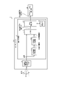
- the signal processing unit 12 includes a 3D (Three Dimensions) object detection unit 121, a 3D object recognition unit 122, an I/F unit 123, a point group correction unit 125, and a storage unit 126.
- 3D Three Dimensions
- 3D object detection unit 121, 3D object recognition unit 122, I/F unit 123, and point group correction unit 125 are executed by executing an information processing program according to the present disclosure on a processor such as a CPU (Central Processing Unit). Can be configured. Not limited to this, part or all of the 3D object detection unit 121, the 3D object recognition unit 122, the I/F unit 123, and the point group correction unit 125 may be configured by hardware circuits that operate in cooperation with each other. good too.
- a processor such as a CPU (Central Processing Unit).
- part or all of the 3D object detection unit 121, the 3D object recognition unit 122, the I/F unit 123, and the point group correction unit 125 may be configured by hardware circuits that operate in cooperation with each other. good too.
- the point cloud output from the light detection and ranging unit 11 is input to the signal processing unit 12 and supplied to the I/F unit 123 and the 3D object detection unit 121 in the signal processing unit 12 .
- the 3D object detection unit 121 detects measurement points indicating a 3D object, included in the supplied point group.
- expressions such as ⁇ detect a measurement point indicating a 3D object included in the synthesized point cloud'' will be replaced with expressions such as ⁇ detect a 3D object included in the synthesized point cloud.'' described in
- the 3D object detection unit 121 detects, from the point cloud, a point cloud that has a velocity and a point cloud that includes the point cloud and has a relationship such as having a connection of a certain density or more, for example, is recognized as a 3D object. It is detected as a point cloud (called a localized point cloud). For example, the 3D object detection unit 121 extracts points having a velocity absolute value greater than or equal to a certain value from the point cloud in order to discriminate between a static object and a dynamic object included in the point cloud. The 3D object detection unit 121 selects a set of point groups localized in a certain spatial range (corresponding to the size of the target object) from the extracted point group as a localized point group corresponding to the 3D object. To detect. The 3D object detection unit 121 may extract a plurality of localized point groups from the point group.
- the 3D object detection unit 121 acquires 3D coordinates and speed information of each point in the detected localized point group. Also, the 3D object detection unit 121 adds label information indicating the 3D object corresponding to the localized point group to the area of the detected localized point group. The 3D object detection unit 121 outputs the 3D coordinates, velocity information, and label information regarding these localized point groups as 3D detection information indicating the 3D detection result.
- the 3D object recognition unit 122 acquires 3D detection information output from the 3D object detection unit 121. Based on the acquired 3D detection information, the 3D object recognition unit 122 performs object recognition for the localized point group indicated by the 3D detection information. For example, when the number of points included in the localized point group indicated by the 3D detection information is equal to or greater than a predetermined number that can be used for recognizing the target object, the 3D object recognition unit 122 performs point group Perform recognition processing. The 3D object recognition unit 122 estimates attribute information about the recognized object by this point group recognition processing.
- the 3D object recognition unit 122 executes object recognition processing on the localized point group corresponding to the 3D object among the point groups output from the light detection and distance measurement unit 11 .
- the 3D object recognition unit 122 removes the point groups other than the local point group from the point group output from the light detection and distance measurement unit 11, and does not perform the object recognition processing on those parts. Therefore, it is possible to reduce the load of recognition processing by the 3D object recognition unit 122 .
- the 3D object recognition unit 122 outputs the recognition result of the localized point group as 3D recognition information when the confidence of the estimated attribute information is equal to or higher than a certain level, that is, when the recognition process can be executed significantly.
- the 3D object recognition unit 122 includes, in the 3D recognition information, 3D coordinates, speed information, attribute information, position, size and orientation of the recognized object, and certainty about the localized point group. can be done.
- the attribute information is information indicating the attributes of the target object, such as the type of the target object to which the unit belongs and the unique classification, for each point of the point cloud as a result of the recognition processing. If the target object is a person, the attribute information can be represented, for example, as a unique numerical value assigned to each point of the point cloud and belonging to the person.
- the 3D recognition information output from the 3D object recognition unit 122 is input to the I/F unit 123.
- the I/F unit 123 also receives the point cloud output from the light detection and distance measurement unit 11 as described above.
- the I/F unit 123 integrates the point cloud with the 3D recognition information and supplies it to the point cloud correction unit 125 .
- the 3D recognition information supplied to the point cloud correction unit 125 here is the 3D recognition information before being corrected by the point cloud correction unit 125 .
- the point cloud correction unit 125 corrects the position information related to the localized point cloud included in the 3D recognition information supplied from the I/F unit 123 .
- the point cloud correction unit 125 performs this correction by estimating position information about the currently acquired localized point cloud using past 3D recognition information about the localized point cloud stored in the storage unit 126. you can go For example, the point cloud correction unit 125 predicts the current position information of the localized point cloud based on the velocity information included in the past 3D recognition information.
- the point cloud correction unit 125 supplies the corrected 3D recognition information to the application execution unit 20 . Also, the point cloud correction unit 125 stores, for example, velocity information and position information included in the 3D recognition information in the storage unit 126 as past information in an accumulative manner.
- the application execution unit 20 is configured according to a predetermined program in a general information processing device including, for example, a CPU (Central Processing Unit), memory, storage device, and the like.
- the application execution unit 20 is not limited to this, and may be implemented by specific hardware.
- the first embodiment is an example in which a manipulation virtual object projected onto a wall surface or the like can be manipulated by a gesture of a user who is an operator.
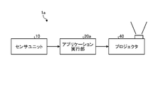
- FIG. 5 is a block diagram showing an example configuration of the sensing system according to the first embodiment.
- the sensing system 1a includes a sensor unit 10, an application executing section 20a, and a projector 40. As shown in FIG. 5,
- the application execution unit 20a can generate a display signal for projecting an image by the projector 40.
- the application execution unit 20a generates a display signal for projecting an image according to the corrected 3D recognition result supplied from the sensor unit 10 .
- the application execution unit 20a also generates a display signal for projecting a fixed image, and a display signal for superimposing and projecting an image corresponding to the corrected 3D recognition result on the fixed image.
- the projector 40 projects an image corresponding to the display signal generated by the application execution unit 20a onto a projection target such as a wall surface.
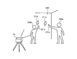
- FIG. 6 is a schematic diagram for explaining an example usage form of the sensing system according to the first embodiment.
- the sensing system 1a according to the first embodiment projects button images 310a and 310b as images to be operated onto a wall surface 300, which is a fixed surface, such as a screen, by a projector 40.
- a cursor image 311 is projected.
- the sensing system 1a detects and recognizes a real object, that is, a hand 321 of an operator 320 using the sensor unit 10, and moves a cursor image 311 according to the movement of the hand 321.
- FIG. 6 is a schematic diagram for explaining an example usage form of the sensing system according to the first embodiment.
- the sensing system 1a according to the first embodiment projects button images 310a and 310b as images to be operated onto a wall surface 300, which is a fixed surface, such as a screen, by a projector 40.
- a cursor image 311 is projected.
- the sensing system 1a detects and recognizes a real
- the application execution unit 20a may execute a predetermined process when at least part of the cursor image 311 overlaps, for example, the button image 310a according to the movement of the hand 321. As an example, in this case, the application executing unit 20a changes the button image 310a to an image indicating that the button image 310a is in the selection standby state.
- the application execution unit 20a causes the hand 321 to intersect the moving surface of the cursor image 311 with at least part of the cursor image 311 overlapping, for example, the button image 310a, and to move the button image. If movement in a direction toward 310a is detected, it may be determined that the button image 310a has been selected, and the function associated with the button image 310a may be performed.
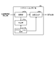
- FIG. 7 is an example functional block diagram for explaining the functions of the application execution unit 20a according to the first embodiment.
- the application execution unit 20a includes a conversion unit 200a, a determination unit 201a, an image generation unit 202a, and an application body 210a.
- the conversion unit 200a, determination unit 201a, image generation unit 202a, and application body 210a are configured by executing a predetermined program on the CPU, for example. Not limited to this, part or all of the conversion unit 200a, determination unit 201a, image generation unit 202a, and application body 210a may be configured by hardware circuits that operate in cooperation with each other.
- an application main body 210a includes an image to be operated by a user (button images 310a and 310b in the example of FIG. 6) and an operation image (cursor image 311 in the example of FIG. 6) for the user to operate. ) and generate
- the application body 210a gives fixed coordinates to the image to be operated and gives initial coordinates to the image for operation.
- the application main body 210a passes the coordinates of the operated image to the determination unit 201a.
- the conversion unit 200a converts the 3D coordinates included in the corrected 3D recognition information supplied from the sensor unit 10 into coordinates on the projection target (the wall surface 300 in the example of FIG. 6) by the projector 40.
- the conversion unit 200a passes the converted coordinates to the determination unit 201a and the image generation unit 202a.
- the coordinates transferred from the conversion unit 200a to the image generation unit 202a are the coordinates of the operation image on the projection target by the projector 40.
- the determination unit 201a determines overlap between the operation image and the operation image based on the coordinates of the operation image and the coordinates of the operation image based on the 3D recognition information passed from the conversion unit 200a. Further, when at least a part of the operated image overlaps the operation image, the determination unit 201a sets the 3D coordinates of the operation image to the operated image based on the speed information included in the 3D recognition information, for example. It is determined whether or not the direction intersecting the display surface changes toward the operated image. For example, when the 3D coordinates for the operation image change toward the operated image with respect to the direction intersecting the display surface of the operated image, it is determined that a predetermined operation has been performed on the operated image. be able to.
- the determination unit 201a passes the determination result to the application body 210a.
- the application main body 210a can execute a predetermined operation according to the determination result passed from the determination unit 201a and, for example, update the operated image.
- the application body 210a passes the updated operated image to the image generator 202a.
- the image generating unit 202a selects the projector 40 as the projection target based on the coordinates of the operated image and the operation image passed from the conversion unit 200a and the images of the operated image and the operation image passed from the application body 210a. Generate an image for projection.
- the image generator 202 a generates a display signal for projecting the generated image, and passes the generated display signal to the projector 40 .
- the projector 40 projects an image onto the projection plane according to the display signal passed from the image generator 202a.
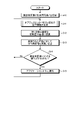
- FIG. 8 is an example flowchart for explaining the operation of the sensing system 1a according to the first embodiment.
- the sensing system 1a causes the projector 40 to project the image to be operated and the image for operation onto the projection target.
- the sensing system 1a acquires the position information of the designated area in the real object by the sensor unit 10.
- FIG. It is possible to designate in advance what kind of area is to be designated as the designated area.
- a real object is, for example, a person who operates an operation image in real space.
- the specified region is a part related to the operation of the operation image among the parts of the person.
- the designated area is the person's hand or a finger protruding from the hand.
- the specified region is not limited to this, and may be a region including the forearm and hand of the person, or may be a leg as well as an arm.
- the sensing system 1a converts the 3D coordinates of the designated area into the coordinates of the projection plane by the conversion unit 200a of the application execution unit 20a.
- the sensing system 1a updates the operation image in the image generator 202a according to the coordinates converted by the converter 200a. The updated operation image is projected onto the projection plane by the projector 40 .
- the determination unit 201a of the application execution unit 20a of the sensing system 1a determines whether or not an operation has been performed on the image to be operated using the operation image.
- the determination unit 201a determines whether an operation is performed when at least a part of the operation image overlaps the image to be operated, based on the coordinates of the operation image converted by the conversion unit 200a based on the 3D coordinates of the specified region. It can be determined that Further, the determination unit 201a may determine that an operation has been performed when an operation such as pressing the operation image is performed when at least a part of the operation image overlaps the image to be operated. .
- step S14 when the determination unit 201a determines that no operation has been performed (step S14, "No"), the sensing system 1a returns the process to step S11. On the other hand, when the determination unit 201a determines in step S14 that an operation has been performed (step S14, "Yes"), the sensing system 1a moves the process to step S15.
- step S15 the sensing system 1a notifies the application body 210a of the determination result that the determination unit 201a has performed an operation. At this time, the sensing system 1a notifies the application body 210a of the content of the operation.
- the contents of the operation include, for example, which image to be operated has been operated, the operation is an operation in which at least part of the operation image is superimposed on the image to be operated, and an operation to press the image to be operated. can include information such as which of the
- step S15 the sensing system 1a returns the process to step S11.
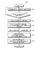
- FIG. 9 is an example flowchart for explaining processing by the sensor unit 10 according to the first embodiment.
- the flowchart of FIG. 9 shows in more detail the processing of step S11 in the flowchart of FIG. 8 described above.
- the sensor unit 10 scans with the light detection and distance measurement unit 11 to acquire a point group. It is assumed that the obtained point cloud includes a point cloud corresponding to the real object as the operator who operates the operation image.
- the sensor unit 10 uses the 3D object detection section 121 to determine whether or not a point group having a speed equal to or higher than a predetermined value exists in the point group acquired in step S110.
- the 3D object detection unit 121 determines that there is no point cloud having a velocity equal to or higher than the predetermined speed (step S111, "No")
- the sensor unit 10 returns the process to step S110.
- the 3D object detection unit 121 determines that there is a point cloud having a speed equal to or higher than the predetermined speed (step S111, "Yes")
- the sensor unit 10 shifts the process to step S112.
- step S112 the sensor unit 10 uses the 3D object detection unit 121 to extract point groups having a velocity equal to or higher than a predetermined speed from the point groups acquired in step S110.
- step S113 the sensor unit 10 extracts the point group extracted in step S112 from the point group acquired in step S110 by the 3D object detection unit 121. is extracted as a localized point group.
- the number of point groups to be processed is reduced by extracting the local point group from the point group obtained by scanning with the light detection and ranging unit 11 using the velocity information of the point group. , can improve responsiveness.
- the sensor unit 10 uses the 3D object recognition section 122 to estimate the designated area based on the localized point group extracted in step S113.
- the designated area is an area corresponding to a part of the person that indicates a position in space, such as a hand, a protruding finger on the hand, or a forearm including the hand.
- the sensing system 1 may be previously designated as to what kind of region is to be designated as the designated region.
- the sensor unit 10 uses the 3D object recognition section 122 to estimate the position and orientation of the designated area estimated in step S114. For example, if the specified area has a shape with long sides and short sides, the orientation of the specified area can be indicated by the direction of the long side or the short side.
- the sensor unit 10 causes the point cloud correction unit 125 to identify velocity information indicating the velocity of the designated region whose position and orientation are estimated in step S115, based on the point cloud acquired in step S110.
- the sensor unit 10 causes the point group correction unit 125 to correct the position and orientation of the designated area estimated in step S115 using the speed information identified in step S116.
- the point cloud correction unit 125 can correct the current position and orientation of the specified region using the past position and orientation of the specified region and the speed information stored in the storage unit 126.
- the point group correction unit 125 can correct the three-dimensional coordinates of the direction indicated by the specified region and the plane intersecting the direction. As a result, it is possible to correct the three-dimensional coordinates associated with the movement and selection (pressing) of the cursor image 311 by the motion of the user's hand 321 shown in FIG. 6, for example.
- the point cloud correction unit 125 passes the localized point cloud of the specified region whose position and orientation have been corrected to the application execution unit 20a. In addition, the point cloud correction unit 125 stores information indicating the corrected position and orientation of the localized point cloud and velocity information of the localized point cloud in the storage unit 126 .
- step S117 After the process of step S117, the process shifts to the process of step S12 in FIG.
- the sensor unit 10 extracts a localized point group corresponding to the designated area from the point group obtained by scanning with the light detection and distance measuring unit 11 .
- the sensor unit 10 corrects the position and orientation of the specified region by the extracted localized point group using the velocity information of the point group obtained by scanning with the light detection and distance measuring unit 11 .
- This correction is the correction of the position and posture of the specified area, which is estimated from the speed information and the delay time information from when the distance is acquired by the light detection and distance measuring unit 11 until when the cursor image 30 is displayed by the projector 40. including.
- the responsiveness is improved by reducing the number of point clouds to be processed, and the responsiveness is improved by estimating the position and orientation based on the velocity information and the delay time until display. In addition, it is possible to improve the stability of the position and orientation of the designated area.
- the coordinates estimated from the speed information and the delay time until display are used as the coordinates of the cursor image 311 instead of the coordinates that are actually detected.
- Coordinates obtained by converting the coordinates to coordinates on the projection target (the wall surface 300 in the example of FIG. 6) by the projector 40 are used. This processing can improve the responsiveness of the display of the cursor image 311 .
- the coordinates detected as the coordinates of the cursor image 311 are subjected to position correction using a low-pass filter, and then the projection target by the projector 40 (see FIG. 6).
- coordinates converted into coordinates on the wall surface 300 are used. This processing can improve the stability of the display of the cursor image 311 .
- This mechanism that prioritizes either stability or responsiveness according to the movement speed can be defined in detail based on the movement speed, and it is possible to switch with less discomfort.
- the first embodiment it is possible to improve the stability and responsiveness of display in response to wide-ranging movements of people and objects other than people.
- the operated image is not limited to the button image, but may be a dial image or a switch image, and the projection surface may not be flat. It is also possible to draw pictures and characters on the wall surface 300 or in the virtual space by operating the operation image.
- FIG. 10 is a schematic diagram for explaining a usage form of an example of the sensing system according to the first modified example of the first embodiment. It should be noted that in FIG. 10, images to be operated (for example, button images 310a and 310b) are omitted.
- Sensing system 1a detects specified areas of operators 320a and 320b (hands, protruding fingers, forearms including hands, etc.) based on point clouds acquired by scanning with light detection and distance measurement unit 11 in sensor unit 10. ). The sensing system 1a can determine which of the cursor images 311a and 311b each of the operators 320a and 320b is to operate based on the positions and orientations of the specified regions of the operators 320a and 320b.
- the sensing system 1a can acquire the operator's gesture and speed information without restricting the operator's actions. Therefore, even when there are a plurality of operators, each of the plurality of operators can use the sensing system 1a in the same manner as when there is only one operator.
- stage effects such as changing the image projected on the wall surface 300 by moving the bodies of a plurality of operators.
- the operator's whole body is designated as a specified region, which is a part related to image manipulation.
- FIG. 11 is a schematic diagram for explaining a usage form of an example of the sensing system according to the second modification of the first embodiment.
- playing a keyboard instrument is applied as an example of operations by fine and quick movements.
- a spectacles-type device compatible with MR has a transmissive display unit, and is capable of displaying a mixture of a scene in a virtual space and a scene in the outside world on the display unit.
- the sensing system 1a uses the application execution unit 20a to display a keyboard instrument 312 (for example, a piano) in the virtual space as an image to be operated on the display unit of the MR-compatible glasses-type device.
- a keyboard instrument 312 for example, a piano
- An operator wearing the spectacles-type device operates (plays) a keyboard instrument 312 in the virtual space displayed on the display unit of the spectacles-type device with hands 322 in the real space.
- the application execution unit 20a is configured to output a sound corresponding to the keyboard when it detects that the keyboard of the keyboard instrument 312 has been pressed.
- the sensing system 1a recognizes the operator's hand 322 with the sensor unit 10, and specifies a virtual hand 330, which is a hand in the virtual space, as a designated region that is a part related to image manipulation.
- a virtual hand 330 which is a hand in the virtual space, as a designated region that is a part related to image manipulation.
- the hand 322 in the real space displayed on the display unit of the glasses-type device functions as the operation image, so the application execution unit 20a does not need to generate the operation image separately.
- the FMCW-LiDAR applied to the photodetector and distance measuring unit 11 can acquire the velocity information of the point cloud, as already described. Therefore, the sensing system 1a estimates the timing at which the position of the fingers of the hand 322 in the real space reaches the keyboard in the virtual space using the speed information of the virtual hand 330 corresponding to the hand 322, It can be assumed that the finger presses the keyboard. Therefore, it is possible to reduce the delay until the sound of the keyboard instrument 312 is output with respect to the movement of the fingers of the hand 322 in the real space.
- the second embodiment is an example in which the sensing system according to the present disclosure is applied to e-sports in which competitions are held in virtual space.
- esports competitors compete in virtual space.
- a competition may be performed by a player operating a controller, or by a player moving their body in the same way as in a competition in real space.
- the second embodiment targets the latter, e-sports, in which players move their bodies in the same way as in competitions in real space.
- FIG. 12 is a schematic diagram for explaining an example usage form of the sensing system according to the second embodiment.
- the sensing system 1b includes a glasses-type device 60a worn by a player 325 and a motion measuring device 50 for measuring the motion of the player 325.
- a motion measuring device 50 for measuring the motion of the player 325.
- the spectacles type device 60a it is preferable to use, for example, the above-described MR compatible device.
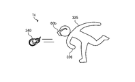
- an e-sports game is assumed in which a player 325 throws a virtual ball 340.
- the virtual ball 340 is displayed on the display section of the glasses-type device 60a and does not exist in real space.
- a player 325 can observe a virtual ball 340 through the glasses-type device 60a.
- the motion measurement device 50 has a light detection and distance measurement unit 11, scans the space including the athlete 325, and acquires a point cloud. Based on the obtained point cloud, the motion measurement device 50 recognizes the hand 326 as an operation area (designated area) in which the player 325 operates (throws, holds, receives, etc.) the virtual ball 340, and the hand 326 Identify the position and posture of At this time, the motion measurement device 50 corrects the specified position and orientation of the hand 326 based on the past position and orientation of the hand 326 and the current speed information. The motion measurement device 50 transmits 3D recognition information including information indicating the corrected position and orientation of the hand 326 to the glasses-type device 60a.
- the glasses-type device 60a displays an image of the virtual ball 340 on the display unit based on the 3D recognition information transmitted from the motion measurement device 50.
- the glasses-type device 60a estimates the behavior of the virtual ball 340 according to the 3D recognition information and identifies the position of the virtual ball 340.
- FIG. For example, when spectacles type device 60a estimates that player 325 is holding virtual ball 340 with hand 326 based on the 3D recognition information, the position of virtual ball 340 is changed to the position corresponding to hand 326. do. Further, for example, when the spectacles-type device 60a deduces that the player 325 is throwing the virtual ball 340 based on the 3D recognition information, the spectacles-type device 60a releases the virtual ball 340 from the hand 326. Move in the direction in which it is assumed to have been thrown.
- FIG. 13 is a block diagram showing an example configuration of a sensing system 1b according to the second embodiment.
- a motion measuring device 50 includes a sensor unit 10 and a communication section 51 .
- the communication unit 51 can transmit the corrected 3D recognition information output from the sensor unit 10 using the antenna 52 .
- the glasses-type device 60a includes a communication section 62, an application execution section 20b, and a display section 63.
- the communication unit 62 receives the 3D recognition information transmitted from the motion measurement device 50 using the antenna 61 and passes it to the application execution unit 20b.
- the application execution unit 20b updates or generates an image of the operated object (virtual ball 340 in the example of FIG. 12) based on the 3D recognition information.
- the updated or generated image of the operated object is sent to the display unit 63 and displayed.
- FIG. 14 is a functional block diagram of an example for explaining the functions of the glasses-type device 60a according to the second embodiment.
- the application execution unit 20b includes a motion information generation unit 212, a conversion unit 200b, and an image generation unit 202b.
- the motion information generation unit 212, the conversion unit 200b, and the image generation unit 202b are configured by executing programs on the CPU.
- the motion information generation unit 212, the conversion unit 200b, and the image generation unit 202b may be configured by hardware circuits that operate in cooperation with each other.
- the motion information generation unit 212 generates motion information indicating the motion (throwing, receiving, holding, etc.) of the player 325 with respect to the operated object based on the 3D recognition information passed from the communication unit 62 .
- the motion information includes, for example, information indicating the position and orientation of the operated object.
- the motion information is not limited to this, and may further include speed information indicating the speed of the operated object.
- the transformation unit 200b transforms the coordinates of the image of the operated object into the coordinates on the display unit 63 of the glasses-type device 60a based on the motion information generated by the motion information generation unit 212.
- the image generation unit 202 b generates an image of the operated object according to the coordinates converted by the conversion unit 200 b and passes the generated image to the display unit 63 .
- the display unit 63 includes a display control unit 64 and a display device 65.
- the display control unit 64 generates a display signal for the display device 65 to display the image of the operated object passed from the application execution unit 20b.
- the display device 65 includes, for example, a display element such as an LCD (Liquid Crystal Display) or an OLED (Organic Light-Emitting Diode), a driving circuit for driving the display element, and an image displayed by the display element on the glasses-type device 60a. and an optical system for projecting onto the surface of the glasses.
- the display device 65 displays the image of the operated object using a display element according to the display signal generated by the display control unit 64, and projects the displayed image onto the surface of the glasses.
- FIG. 15 is an example flowchart for explaining the operation of the sensing system 1b according to the second embodiment.
- step S20 the sensing system 1b acquires the position of the point cloud of the operation area (for example, the hand 326 of the player 325) by the sensor unit 10.
- the sensing system 1b causes the motion information generation unit 212 to generate the position, orientation, and motion of the manipulation object (for example, the virtual ball 340) based on the point cloud of the manipulation region acquired in step S20.
- the sensing system 1b uses the image generation unit 202b to generate an image of the manipulation object based on the position, posture, and motion of the manipulation object generated in step S21.
- the image generation unit 202 b passes the generated image of the operation object to the display unit 63 .
- FIG. 16 is an example flowchart for explaining processing by the sensor unit 10 according to the second embodiment.
- the flowchart of FIG. 16 shows in more detail the process of step S20 in FIG. 15 described above.
- the sensor unit 10 scans with the light detection and distance measurement section 11 to acquire a point group. It is assumed that the acquired point cloud includes the point cloud corresponding to the real object as the operator (player 325 in the example of FIG. 12) who operates the operation object.
- the sensor unit 10 uses the 3D object detection section 121 to determine whether or not a point group having a velocity equal to or higher than a predetermined value exists in the point group acquired in step S200.
- the 3D object detection unit 121 determines that there is no point cloud having a velocity equal to or higher than the predetermined speed (step S201, "No")
- the sensor unit 10 returns the process to step S200.
- the 3D object detection unit 121 determines that there is a point cloud having a speed equal to or higher than the predetermined speed
- the sensor unit 10 shifts the process to step S202.
- step S202 the sensor unit 10 uses the 3D object detection unit 121 to extract point groups having a velocity equal to or higher than a predetermined speed from the point groups acquired in step S200.
- step S203 the sensor unit 10 converts the point cloud acquired in step S200 to the point cloud extracted in step S202 by the 3D object detection unit 121. is extracted as a localized point group.
- the sensor unit 10 uses the 3D object recognition section 122 to estimate the operator (player 325 in the example of FIG. 12) based on the localized point group extracted in step S203.
- the sensor unit 10 causes the 3D object recognition unit 122 to estimate the position of the operation area from the point cloud of the operator estimated in step S204, Add an attribute that indicates the operation area.
- the sensor unit 10 moves the position of the point cloud having the attribute indicating the operation area to the operation area identified in step S205 using the velocity information indicated by the point cloud acquired in step S200. Correct the position of the corresponding point cloud.
- the point cloud correction unit 125 can correct the current position of the operation area using the past position and speed information regarding the operation area stored in the storage unit 126 .
- the point cloud correction unit 125 passes the position-corrected point cloud of the operation area to the application execution unit 20b. Also, the point cloud correction unit 125 stores the corrected position and speed information of the point cloud in the storage unit 126 .
- step S206 After the process of step S206, the process shifts to the process of step S21 in FIG.
- the sensor unit 10 extracts a localized point group corresponding to the operator from the point group obtained by scanning with the light detection and ranging unit 11, and further extracts the localized point group. Extract the point cloud of the operation area from the point cloud.
- the sensor unit 10 corrects the position of the operation region based on the extracted point group using velocity information of the point group acquired by scanning with the light detection and distance measuring unit 11 . Therefore, by applying the second embodiment, the number of point groups to be processed can be reduced, and responsiveness can be improved. can be suppressed. Therefore, by applying the second embodiment, it is possible to improve the responsiveness of display in response to wide-ranging movements of people and objects other than people. This allows the operator, who is the player 325, to comfortably operate the operation object.
- FIG. 17 is a block diagram showing an example configuration of a sensing system according to a modification of the second embodiment.
- the sensing system 1c includes an MR-compatible glasses-type device 60b.
- FIG. 18 is a block diagram showing an example configuration of a sensing system 1c according to a modification of the second embodiment.
- a glasses-type device 60b includes a sensor unit 10, an application execution section 20b, and a display section 63.
- the sensor unit 10 for example, is incorporated into the spectacles-type device 60b so as to be able to scan the player's 325 operation area (for example, the hand 326).
- the player 325 can observe the virtual ball 340 by wearing the glasses type device 60b.
- a space including a hand 326 as an operation area of the player 325 is scanned by the light detection and distance measurement section 11 in the sensor unit 10 incorporated in the glasses-type device 60b.
- the sensor unit 10 extracts a group of localized points corresponding to the hand 326 based on the group of points obtained by scanning, and assigns attributes to the extracted group of localized points.
- the sensor unit 10 corrects the position of the attributed localized point group based on the velocity information including the past of the localized point group, and outputs 3D recognition information in which the position of the localized point group is corrected.
- the application execution unit 20b generates an image of the operation object (virtual ball 340 in the example of FIG. 17) based on the 3D recognition information output from the sensor unit 10.
- the image of the operation object generated by the application execution unit 20b is transferred to the display unit 63 and projected onto the display device 65 for display.
- the player 325 can play e-sports by using only the glasses-type device 60b, and the system configuration can be reduced. .
- the third embodiment is an example in which the sensing system according to the present disclosure is applied to projection mapping.
- Projection mapping is a technique for projecting an image onto a three-dimensional object using projection equipment such as a projector.
- projection mapping according to the third embodiment an image is projected onto a moving three-dimensional object.
- moving three-dimensional objects will be referred to as “moving bodies” as appropriate.
- FIG. 19 is a schematic diagram for explaining an example usage form of the sensing system according to the third embodiment.
- the sensing system 1d scans a space containing a rotating moving body 350 as a real object and identifies the moving body 350, as indicated by arrows in the drawing. Further, the sensing system 1d may determine the surface of the moving object 350 facing the measurement direction of the light detection and distance measurement unit 11 as the specified area.
- the sensing system 1 d includes a projector and projects a projection image 360 onto the specified moving body 350 .
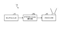
- FIG. 20 is a block diagram showing an example configuration of a sensing system 1d according to the third embodiment.
- the sensing system 1d includes a sensor unit 10, an application executing section 20c, and a projector 40.
- the application execution unit 20c transforms an image based on the 3D recognition result obtained by scanning the space including the moving body 350 with the sensor unit 10, and generates a projection image 360 to be projected by the projector 40.
- FIG. A projection image 360 generated by the application execution unit 20 c is projected onto the moving body 350 by the projector 40 .
- FIG. 21 is an example functional block diagram for explaining the functions of the application execution unit 20c according to the third embodiment.
- the application execution unit 20c includes a conversion unit 200c, an image generation unit 202c, and an application body 210c.
- the conversion unit 200c, the image generation unit 202c, and the application body 210c are configured by executing programs on the CPU.
- the conversion unit 200c, the image generation unit 202c, and the application body 210c may be configured by hardware circuits that operate in cooperation with each other.
- the transformation unit 200c performs coordinate transformation according to the projection plane of the moving body 350 based on the position and orientation of the moving body 350 indicated in the corrected 3D recognition information supplied from the sensor unit 10.
- the conversion unit 200c passes the coordinate information subjected to the coordinate conversion to the image generation unit 202c.
- the application main body 210c has in advance a projection image (or video) to be projected onto the moving body 350.
- the application body 210c passes the projection image to the image generator 202c.
- the image generation unit 202c transforms the projection image passed from the application body 210c based on the coordinate information passed from the conversion unit 200c, and passes the transformed projection image to the projector 40.
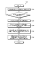
- FIG. 22 is an example flowchart for explaining the operation of the sensing system 1d according to the third embodiment. It is assumed that the application main body 210c has a projection image in advance. A projection image may be a still image or a moving image.
- step S30 the sensing system 1d acquires information on the projection surface of the moving body 350 onto which the image (video) from the projector 40 is projected, based on the point group acquired by scanning the space including the moving body 350 with the sensor unit 10. to get The projection plane information includes coordinate information indicating the 3D coordinates of the projection plane in real space.
- the sensing system 1d causes the application execution unit 20c to convert, for example, the shape of the projection image into a shape corresponding to the projection plane based on the coordinate information of the projection plane acquired in step S30.
- the sensing system 1d causes the projector 40 to project the image for projection whose shape has been transformed in step S31 onto the projection surface of the moving object 350.
- FIG. 23 is an example flowchart for explaining the processing by the sensor unit 10 according to the third embodiment.
- the flowchart of FIG. 23 shows in more detail the process of step S30 in the flowchart of FIG. 22 described above.
- the 3D object recognition unit 122 pre-registers information on the moving object 350 prior to the processing according to the flowchart of FIG.
- the 3D object recognition unit 122 can pre-register information such as shape, size, weight, movement pattern, and movement speed as information of the moving body 350 .
- step S301 the sensor unit 10 scans the space including the moving object 350 with the light detection and distance measurement unit 11, and acquires a point group.
- the sensor unit 10 uses the 3D object detection unit 121 to determine whether or not a point group having a velocity equal to or higher than a predetermined value exists in the point group acquired in step S301.
- the 3D object detection unit 121 determines that there is no point cloud having a speed equal to or higher than the predetermined speed (step S302, "No")
- the sensor unit 10 returns the process to step S301.
- the 3D object detection unit 121 determines that there is a point cloud having a speed equal to or higher than the predetermined speed (step S302, "Yes")
- the sensor unit 10 shifts the process to step S303.
- step S303 the sensor unit 10 uses the 3D object detection unit 121 to extract point groups having a speed equal to or higher than a predetermined speed from the point groups acquired in step S301.
- step S304 the sensor unit 10 converts the point cloud acquired in step S301 to the point cloud extracted in step S303 by the 3D object detection unit 121. is extracted as a localized point group.
- the sensor unit 10 uses the 3D object recognition section 122 to recognize the object including the projection plane based on the localized point group.
- the 3D object recognition unit 122 identifies which of the pre-registered objects the recognized object is.
- the sensor unit 10 causes the point cloud correction unit 125 to generate a point cloud of an object (moving body 350 in the example of FIG. 19) including the projection plane, recognition results, and velocity information including the past of the point cloud. and correct the position of the point cloud.
- the point cloud correction unit 125 can correct the current position and orientation of the projection plane using the past position and orientation of the projection plane and the velocity information stored in the storage unit 126.
- the point group correction unit 125 further adds information about this moving body 350 when correcting the position and orientation of the projection plane. can be used.
- the point cloud correction unit 125 passes the localized point cloud of the specified region whose position and orientation have been corrected to the application execution unit 20c. In addition, the point cloud correction unit 125 stores information indicating the corrected position and orientation of the point cloud on the projection plane and velocity information of the point cloud in the storage unit 126 .
- step S306 After the process of step S306, the process shifts to the process of step S31 in FIG.
- the position and orientation of the projection plane projected by the projector 40 on the moving body 350 are combined with the past position and orientation of the projection plane and velocity information by the point group correction unit 125. is corrected using Therefore, by applying the third embodiment to projection mapping, it is possible to reduce the displacement of the projection position when an image or video is projected onto the moving body 350 in motion, and to produce a presentation with less sense of discomfort. It becomes possible. Therefore, by applying the third embodiment, it is possible to improve the responsiveness of display in response to wide-ranging movements of people and objects other than people.
- an imaging device is provided in addition to the light detection and distance measurement unit 11 in the sensor unit, and the point cloud acquired by the light detection and distance measurement unit 11 and the captured image captured by the imaging device are used to detect the object. This is an example in which recognition is performed and 3D recognition information is obtained.
- An imaging device capable of acquiring a captured image having information on each color of R (red), G (green), and B (blue) generally has a resolution is much higher. Therefore, by performing the recognition processing using the light detection and ranging unit 11 and the imaging device, the detection and recognition processing can be performed using only the point group information from the light detection and ranging unit 11, thereby achieving higher accuracy. Detection and recognition processing can be executed.
- FIG. 24 is a block diagram showing an example configuration of a sensing system according to the fourth embodiment.
- the sensing system according to the fourth embodiment is applied to the e-sports explained using the second embodiment.
- the sensing system 1e includes a sensor unit 10a and an application executing section 20b.
- the sensor unit 10a includes a light detection and ranging section 11, a camera 14, and a signal processing section 12a.
- the camera 14 is an imaging device capable of acquiring a captured image having information of each color of RGB, and is capable of acquiring a captured image with a higher resolution than the resolution of the point group acquired by the light detection and distance measuring unit 11 .
- the light detection and distance measurement unit 11 and the camera 14 are arranged so as to acquire information in the same direction.
- the light detection and distance measurement unit 11 and the camera 14 are adapted to match the attitude, position, and size relationship for each field of view, and each point included in the point group acquired by the light detection and distance measurement unit 11, It is assumed that the correspondence relationship with each pixel of the captured image acquired by the camera 14 is acquired in advance.
- the light detection and ranging unit 11 and the camera 14 are installed so as to be able to scan and image a space containing a 3D object (for example, a person) to be measured.
- the signal processing unit 12a includes a 3D object detection unit 121a, a 3D object recognition unit 122a, a 2D object detection unit 151, a 2D object recognition unit 152, an I/F unit 160a, a point group correction unit 125, and a storage unit. 126 and .
- a point group having velocity information output from the light detection and distance measurement unit 11 is supplied to the I/F unit 160a and the 3D object detection unit 121a.
- the 3D object detection unit 121a similarly to the 3D object detection unit 121 in FIG. It is detected as a localized point cloud corresponding to the 3D object.
- the 3D object detection unit 121a acquires 3D coordinates and speed information of each point in the detected localized point group.
- the 3D object detection unit 121a adds label information indicating the 3D object corresponding to the localized point group to the area of the detected localized point group.
- the 3D object detection unit 121a outputs the 3D coordinates, velocity information, and label information regarding these localized point groups as 3D detection information indicating the 3D detection result.
- the 3D object detection unit 121a further outputs information indicating the area containing the localized point group to the 2D object detection unit 151 as 3D information.
- a captured image output from the camera 14 is supplied to the I/F section 160 a and the 2D object detection section 151 .
- the 2D object detection unit 151 converts the 3D area information supplied from the 3D object detection unit 121a into 2D area information, which is two-dimensional information corresponding to the captured image.
- the 2D object detection unit 151 cuts out the image of the area indicated by the 2D area information from the captured image supplied from the camera 14 as a partial image.
- the 2D object detection unit 151 supplies the 2D area information and the partial image to the 2D object recognition unit 152 .
- the 2D object recognition unit 152 performs recognition processing on the partial image supplied from the 2D object detection unit 151, and adds attribute information as a recognition result to each pixel of the partial image. As described above, the 2D object recognition section 152 supplies the partial image including the attribute information and the 2D area information to the 3D object recognition section 122a. Also, the 2D object recognition unit 152 supplies the 2D area information to the I/F unit 160a.
- the 3D object recognition unit 122a similarly to the 3D object recognition unit 122 in FIG. Based on the 2D area information, object recognition is performed for the localized point group indicated by the 3D detection information.
- the 3D object recognition unit 122a estimates attribute information about the recognized object by this point group recognition processing.
- the 3D object recognition unit 122a further adds the estimated attribute information to each pixel of the partial image.
- the 3D object recognition unit 122a outputs the recognition result for the localized point group as 3D recognition information when the confidence of the estimated attribute information is equal to or higher than a certain level.
- the 3D object recognition unit 122a includes, in the 3D recognition information, 3D coordinates, speed information, attribute information, the position, size and orientation of the recognized object, and certainty about the localized point group. can be done.
- the 3D recognition information is input to the I/F section 160a.
- the I/F unit 160a receives the point cloud supplied from the light detection and distance measurement unit 11, the captured image supplied from the camera 14, the 3D recognition information supplied from the 3D object recognition unit 122a, and the 2D object recognition unit 152a. and the specified information among the 2D region information supplied from .
- the I/F unit 160a outputs the 3D recognition information as 3D recognition information before correction.
- the processing in the point cloud correction unit 125 is the same as the processing described using FIG. 4, so the description is omitted here.
- FIG. 25 is an example flowchart for explaining processing by the sensor unit 10a according to the fourth embodiment.
- the sensing system 1e according to the fourth embodiment is applied to the e-sports described using the second embodiment, and the flow chart of FIG. It shows the processing of S20 in more detail. Note that this is not limited to this example.
- the sensing system 1e is also applicable to the first embodiment, its modifications, and the third embodiment.
- step S210 the sensor unit 10a scans with the light detection and distance measurement unit 11 to acquire a point group. It is assumed that the obtained point cloud includes a point cloud corresponding to the real object as the operator who operates the operation image.
- step S220 the sensor unit 10a captures an image with the camera 14 and acquires a captured image.
- the acquired captured image is supplied to the I/F section 160 a and the 2D object detection section 151 .
- step S221 the process proceeds to step S221 after waiting for the process of step S214, which will be described later.
- the sensor unit 10a determines whether a point group having a speed equal to or greater than a predetermined value exists in the point cloud acquired in step S210 by the 3D object detection unit 121a. Determine whether or not When the 3D object detection unit 121a determines that there is no point cloud having a velocity equal to or higher than the predetermined speed (step S211, "No"), the sensor unit 10a returns the process to step S210. On the other hand, when the 3D object detection unit 121a determines that there is a point cloud having a speed equal to or higher than the predetermined speed (step S211, "Yes"), the sensor unit 10a shifts the process to step S212.
- step S212 the sensor unit 10a uses the 3D object detection unit 121a to extract point groups having a speed equal to or higher than a predetermined speed from the point groups acquired in step S210.
- the sensor unit 10a converts the point group extracted in step S212 from the point group acquired in step S210 by the 3D object detection unit 121a, for example, a point group having connections with a certain density or more. is extracted as a localized point group.
- the sensor unit 10a uses the 3D object detection section 121a to estimate the designated area based on the localized point group extracted in step S213.
- the designated area is an operation area in the player 325 for the player 325 to operate the virtual game equipment (such as the virtual ball 340) in this example where the sensing system 1e is applied to e-sports.
- the area to be designated as the designated area can be designated in advance to the sensing system 1e.
- the 3D object detection unit 121a passes the designated area estimated in step S214 to the 2D object detection unit 151 as 3D area information.
- step S221 the 2D object detection unit 151 extracts the captured image area corresponding to the operation area in the point cloud as a partial image based on the 3D area information passed from the 3D object detection unit 121a. Also, the 2D object detection unit 151 converts the 3D area information into 2D area information. The 2D object detection unit 151 passes the extracted partial image and the 2D area information obtained by converting the 3D area information to the 2D object recognition unit 152 .
- the 2D object recognition unit 152 executes recognition processing on the partial image extracted in step S221, and the pixels included in the specified region in the partial image are given as a result of the recognition processing. attribute.
- the 2D object recognition unit 152 supplies the partial image including the attribute information and the 2D area information to the 3D object recognition unit 122a.
- step S215 the sensor unit 10a uses the 3D object recognition unit 122a to convert the attribute information obtained by the 2D object recognition unit 152 in accordance with the recognition processing of the partial image into the attribute information estimated by the 3D object detection unit 121a in step S214. Append to the point cloud in the specified region.
- the 3D object recognition unit 122a recognizes the 3D coordinates of the point cloud in the designated area, velocity information, attribute information added to the point cloud by recognition processing for the partial image, and the position, size, and distance of the recognized object. 3D attribute information including pose and certainty is output.
- the 3D recognition information output from the 3D object recognition section 122a is supplied to the point group correction section 125 via the I/F section 160a.
- the sensor unit 10a causes the point group correction unit 125 to correct the position of the designated area estimated in step S214 using the velocity information included in the 3D recognition information.
- the point cloud correction unit 125 can correct the current position of the specified area using past positions and velocity information regarding the specified area, which are stored in the storage unit 126. .
- the point cloud correction unit 125 may further correct the orientation of the designated region.
- the point cloud correction unit 125 passes the position-corrected point cloud of the specified region to the application execution unit 20b. In addition, the point cloud correction unit 125 stores information indicating the corrected position and orientation of the localized point cloud and velocity information of the localized point cloud in the storage unit 126 .
- the captured image captured by the camera 14, which has much higher resolution than the point group is used. Attribute information is added to the 3D object recognition result. Therefore, in the fourth embodiment, it is possible to improve the responsiveness of the display in response to the movement of a person or an object other than a person over a wide range. Attribute information can be added to the point group with higher accuracy than when 3D object recognition is performed using .
- a point group containing velocity information and the three-dimensional coordinates of the point group are output.
- a recognition unit that performs recognition processing based on the point cloud, determines a designated area in a real object, and outputs three-dimensional recognition information including information indicating the determined designated area;
- a correction unit that corrects the three-dimensional coordinates of the specified region in the point group based on the three-dimensional recognition information output by the recognition unit; comprising Information processing equipment.
- the correction unit is correcting the three-dimensional coordinates of the designated area using the three-dimensional coordinates based on the point group output in the past by the light detection and ranging unit;
- the information processing device according to (1) above.
- the correction unit is predicting and correcting the three-dimensional coordinates of the designated area based on velocity information indicated by the point group;
- the real object is a person, and the designated area is an arm or leg of the person;
- the correction unit is correcting the three-dimensional coordinates of the specified area with respect to the direction indicated by the specified area and the plane intersecting the direction;
- the information processing device according to (4) above.
- the real object is a moving body, and the designated area is a surface of the moving body facing the measurement direction by the light detection and distance measuring unit, The information processing apparatus according to any one of (1) to (3).
- a generation unit that generates a display signal for displaying a virtual object based on the three-dimensional coordinates of the specified area corrected by the correction unit; further comprising The information processing apparatus according to any one of (1) to (6).
- the generating unit generating the display signal for projecting an image of the virtual object onto a fixed surface;
- the information processing device according to (7) above.
- the generating unit transforming the coordinates of the image of the virtual object into the coordinates of the fixed surface based on the three-dimensional coordinates of the designated area and the three-dimensional coordinates of the fixed surface;
- the information processing device according to (8) above.
- the generating unit generating the display signal for displaying the image of the virtual object on a display unit of a glasses-type device worn by a user; The information processing device according to (7) above.
- the generating unit generating the display signal for displaying the image of the virtual object on the real object, which is a moving body;
- the correction unit is determining a surface of the real object, which is the moving body, facing the light detection and ranging unit as the specified area;
- the generating unit transforming the coordinates of the image of the virtual object into the three-dimensional coordinates of the designated area;
- the information processing device according to (11) above.
- a point group containing velocity information and the three-dimensional coordinates of the point group are output.
- a light detection and ranging unit using a continuous frequency modulated wave that outputs a point group containing velocity information and three-dimensional coordinates of the point group based on a received signal received after being reflected by an object; a recognition unit that performs recognition processing based on the point cloud, determines a designated area in a real object, and outputs three-dimensional recognition information including information indicating the determined designated area; a correction unit that corrects the three-dimensional coordinates of the specified region in the point group based on the three-dimensional recognition information output by the recognition unit; comprising sensing system.
Landscapes
- Engineering & Computer Science (AREA)
- Physics & Mathematics (AREA)
- Electromagnetism (AREA)
- General Physics & Mathematics (AREA)
- Computer Networks & Wireless Communication (AREA)
- Radar, Positioning & Navigation (AREA)
- Remote Sensing (AREA)
- General Engineering & Computer Science (AREA)
- Theoretical Computer Science (AREA)
- Human Computer Interaction (AREA)
- Position Input By Displaying (AREA)
Abstract
Description
1.本開示の概略
1-1.LiDARについて
1-2.FMCW-LiDARについて
1-3.本開示に適用可能な構成
2.第1の実施形態
2-1.第1の実施形態の第1の変形例
2-2.第1の実施形態の第2の変形例
3.第2の実施形態
3-1.第2の実施形態の変形例
4.第3の実施形態
5.第4の実施形態
本開示は、人によるジェスチャや、人以外の物体の動きに応じて仮想空間に対して仮想オブジェクトを表示させる際に用いて好適な技術に関する。本開示では、人や人以外の物体の動きを、これら対象に対して測距を行うことで検出する。本開示の各実施形態の説明に先立って、本開示に適用される、人や人以外の物体の動きを検出するための測距方法について、概略的に説明する。
実オブジェクトの動きを検出するための方法として、LiDAR(Laser Imaging Detection and Ranging)を用いる方法が知られている。LiDARは、対象物体に照射したレーザ光の反射光を受光した受光信号に基づき当該対象物体までの距離を計測する光検出測距装置である。LiDARでは、レーザ光の走査を行う走査器や、受光部としての焦点面アレイ型検出器などを併せて用いる。LiDARでは、空間に対するレーザ光の走査視囲における角度ごとに測距を実行し、角度と距離との情報に基づき点群と呼ばれるデータを出力する。
ここで、LiDARを用いた光検出測距方法の一つとしての、FMCW(周波数連続変調:Frequency Modulated Continuous Wave)-LiDARについて説明する。FMCW-LiDARは、射出するレーザ光として、時間の経過に応じてパルスの周波数を例えば直線的に変化させたチャープ光を用いる。FMCW-LiDARでは、チャープ光として射出するレーザ光と、射出されたレーザ光の反射光とを合成した受信信号に対し、コヒーレント検出により測距を行う。
次に、本開示に適用可能な構成について説明する。図1は、本開示の各実施形態に適用可能なセンシングシステム1の一例の構成を示すブロック図である。図1において、センシングシステム1は、センサユニット10と、センサユニット10から出力される出力信号に応じて所定の動作を実行するアプリケーション実行部20と、を含む。
次に、本開示の第1の実施形態について説明する。第1の実施形態は、壁面などに投影される操作用の仮想オブジェクトを、操作者であるユーザのジェスチャにより操作可能とした例である。
次に、第1の実施形態の第1の変形例について説明する。上述の第1の実施形態では、1人の操作者が操作用画像(カーソル画像311)により操作を行うように説明した。これに対して、第1の実施形態の第1の変形例は、複数の操作者がそれぞれ操作用画像を用いて操作を行う例である。
次に、第1の実施形態の第2の変形例について説明する。上述の第1の実施形態では、操作者が操作用画像(カーソル画像311)により操作を行うように説明した。これに対して、第1の実施形態の第2の変形例では、操作者が細かく素早い動きによる操作を行う例である。
次に、本開示の第2の実施形態について説明する。第2の実施形態は、本開示に係るセンシングシステムを、仮想空間上で競技を行うeスポーツに適用した例である。
次に、第2の実施形態の変形例について説明する。上述した第2の実施形態では、センサユニット10を、メガネ型デバイスの外部に設けた構成とした。これに対して、第2の実施形態の変形例は、センサユニット10をメガネ型デバイスに組み込んだ構成とした例である。
次に、本開示の第3の実施形態について説明する。第3の実施形態は、本開示に係るセンシングシステムをプロジェクションマッピングに適用した例である。プロジェクションマッピングは、プロジェクタなどの映写機器を用いて立体物に映像を投影する技術である。第3の実施形態に係るプロジェクションマッピングでは、動く立体物に対して映像を投影する。
次に、本開示の第4の実施形態について説明する。第4の実施形態は、センサユニットにおいて、光検出測距部11に加えて撮像装置を設け、光検出測距部11により取得した点群と、撮像装置により撮像した撮像画像とを用いて物体認識を行い、3D認識情報を得るようにした例である。
(1)
対象物で反射されて受信された受信信号に基づき、速度情報を含む点群と、前記点群の3次元座標とを出力する、周波数連続変調波を用いた光検出測距部により出力された前記点群に基づき認識処理を行い実オブジェクトにおける指定領域を決定し、決定した前記指定領域を示す情報を含む3次元認識情報を出力する認識部と、
前記認識部により出力された前記3次元認識情報に基づき前記点群における前記指定領域の3次元座標を補正する補正部と、
を備える、
情報処理装置。
(2)
前記補正部は、
前記指定領域の3次元座標を、前記光検出測距部により過去に出力された前記点群に基づく3次元座標を用いて補正する、
前記(1)に記載の情報処理装置。
(3)
前記補正部は、
前記指定領域の3次元座標を、前記点群により示される速度情報に基づき予測して補正する、
前記(1)または(2)に記載の情報処理装置。
(4)
前記実オブジェクトは人であり、前記指定領域は、前記人の腕または足である、
前記(1)乃至(3)の何れかに記載の情報処理装置。
(5)
前記補正部は、
前記指定領域の、前記指定領域により指し示される方向と、該方向に対して交わる面と、に対する3次元座標をそれぞれ補正する、
前記(4)に記載の情報処理装置。
(6)
前記実オブジェクトは運動体であり、前記指定領域は、前記運動体の前記光検出測距部による計測方向に向かう面である、
前記(1)乃至(3)の何れかに記載の情報処理装置。
(7)
前記補正部により補正された前記指定領域の3次元座標に基づき仮想オブジェクトを表示するための表示信号を生成する生成部、
をさらに備える、
前記(1)乃至(6)の何れかに記載の情報処理装置。
(8)
前記生成部は、
前記仮想オブジェクトの画像を固定面に投影するための前記表示信号を生成する、
前記(7)に記載の情報処理装置。
(9)
前記生成部は、
前記指定領域の3次元座標と、前記固定面の3次元座標とに基づき、前記仮想オブジェクトの画像の座標を前記固定面の座標に変換する、
前記(8)に記載の情報処理装置。
(10)
前記生成部は、
前記仮想オブジェクトの画像をユーザが装着するメガネ型デバイスの表示部に表示させるための前記表示信号を生成する、
前記(7)に記載の情報処理装置。
(11)
前記生成部は、
前記仮想オブジェクトの画像を運動体である前記実オブジェクトに表示させるための前記表示信号を生成する、
前記(7)に記載の情報処理装置。
(12)
前記補正部は、
前記運動体である前記実オブジェクトの前記光検出測距部に向かう面を前記指定領域に決定し、
前記生成部は、
前記仮想オブジェクトの画像の座標を前記指定領域の3次元座標に変換する、
前記(11)に記載の情報処理装置。
(13)
プロセッサにより実行される、
対象物で反射されて受信された受信信号に基づき、速度情報を含む点群と、前記点群の3次元座標とを出力する、周波数連続変調波を用いた光検出測距部により出力された前記点群に基づき認識処理を行い実オブジェクトにおける指定領域を決定し、決定した前記指定領域を示す情報を含む3次元認識情報を出力する認識ステップと、
前記認識ステップにより出力された前記3次元認識情報に基づき前記点群における前記指定領域の3次元座標を補正する補正ステップと、
を有する、
情報処理方法。
(14)
対象物で反射されて受信された受信信号に基づき、速度情報を含む点群と、前記点群の3次元座標とを出力する、周波数連続変調波を用いた光検出測距部と、
前記点群に基づき認識処理を行い実オブジェクトにおける指定領域を決定し、決定した前記指定領域を示す情報を含む3次元認識情報を出力する認識部と、
前記認識部により出力された前記3次元認識情報に基づき前記点群における前記指定領域の3次元座標を補正する補正部と、
を備える、
センシングシステム。
10,10a センサユニット
11 光検出測距部
12,12a 信号処理部
14 カメラ
20a,20b,20c アプリケーション実行部
40 プロジェクタ
50 動作計測装置
51,62 通信部
60a,60b メガネ型デバイス
63 表示部
100 走査部
101 光送信部
102 PBS
103 光受信部
111 走査制御部
112 角度検出部
116 送信光制御部
117 受信信号処理部
130 点群生成部
121,121a 3D物体検出部
122,122a 3D物体認識部
125 点群補正部
126 記憶部
151 2D物体検出部
152 2D物体認識部
200a,200b,200c 変換部
201a 判定部
202a,202b,202c 画像生成部
210a,210c アプリケーション本体
212 動作情報生成部
300 壁面
310a,310b ボタン画像
311,311a,311b カーソル画像
312 鍵盤楽器
320,320a,320b 操作者
321,321a,321b,322,326 手
325 競技者
330 仮想手
340 仮想のボール
350 運動体
360 投影用画像
Claims (14)
- 対象物で反射されて受信された受信信号に基づき、速度情報を含む点群と、前記点群の3次元座標とを出力する、周波数連続変調波を用いた光検出測距部により出力された前記点群に基づき認識処理を行い実オブジェクトにおける指定領域を決定し、決定した前記指定領域を示す情報を含む3次元認識情報を出力する認識部と、
前記認識部により出力された前記3次元認識情報に基づき前記点群における前記指定領域の3次元座標を補正する補正部と、
を備える、
情報処理装置。 - 前記補正部は、
前記指定領域の3次元座標を、前記光検出測距部により過去に出力された前記点群に基づく3次元座標を用いて補正する、
請求項1に記載の情報処理装置。 - 前記補正部は、
前記指定領域の3次元座標を、前記点群により示される速度情報に基づき予測して補正する、
請求項1に記載の情報処理装置。 - 前記実オブジェクトは人であり、前記指定領域は、前記人の腕または足である、
請求項1に記載の情報処理装置。 - 前記補正部は、
前記指定領域の、前記指定領域により指し示される方向と、該方向に対して交わる面と、に対する3次元座標をそれぞれ補正する、
請求項4に記載の情報処理装置。 - 前記実オブジェクトは運動体であり、前記指定領域は、前記運動体の前記光検出測距部による計測方向に向かう面である、
請求項1に記載の情報処理装置。 - 前記補正部により補正された前記指定領域の3次元座標に基づき仮想オブジェクトを表示するための表示信号を生成する生成部、
をさらに備える、
請求項1に記載の情報処理装置。 - 前記生成部は、
前記仮想オブジェクトの画像を固定面に投影するための前記表示信号を生成する、
請求項7に記載の情報処理装置。 - 前記生成部は、
前記指定領域の3次元座標と、前記固定面の3次元座標とに基づき、前記仮想オブジェクトの画像の座標を前記固定面の座標に変換する、
請求項8に記載の情報処理装置。 - 前記生成部は、
前記仮想オブジェクトの画像をユーザが装着するメガネ型デバイスの表示部に表示させるための前記表示信号を生成する、
請求項7に記載の情報処理装置。 - 前記生成部は、
前記仮想オブジェクトの画像を運動体である前記実オブジェクトに表示させるための前記表示信号を生成する、
請求項7に記載の情報処理装置。 - 前記補正部は、
前記運動体である前記実オブジェクトの前記光検出測距部に向かう面を前記指定領域に決定し、
前記生成部は、
前記仮想オブジェクトの画像の座標を前記指定領域の3次元座標に変換する、
請求項11に記載の情報処理装置。 - プロセッサにより実行される、
対象物で反射されて受信された受信信号に基づき、速度情報を含む点群と、前記点群の3次元座標とを出力する、周波数連続変調波を用いた光検出測距部により出力された前記点群に基づき認識処理を行い実オブジェクトにおける指定領域を決定し、決定した前記指定領域を示す情報を含む3次元認識情報を出力する認識ステップと、
前記認識ステップにより出力された前記3次元認識情報に基づき前記点群における前記指定領域の3次元座標を補正する補正ステップと、
を有する、
情報処理方法。 - 対象物で反射されて受信された受信信号に基づき、速度情報を含む点群と、前記点群の3次元座標とを出力する、周波数連続変調波を用いた光検出測距部と、
前記点群に基づき認識処理を行い実オブジェクトにおける指定領域を決定し、決定した前記指定領域を示す情報を含む3次元認識情報を出力する認識部と、
前記認識部により出力された前記3次元認識情報に基づき前記点群における前記指定領域の3次元座標を補正する補正部と、
を備える、
センシングシステム。
Priority Applications (2)
| Application Number | Priority Date | Filing Date | Title |
|---|---|---|---|
| US18/264,862 US20240103133A1 (en) | 2021-03-17 | 2021-12-23 | Information processing apparatus, information processing method, and sensing system |
| CN202180095515.2A CN116964484A (zh) | 2021-03-17 | 2021-12-23 | 信息处理设备、信息处理方法和感测系统 |
Applications Claiming Priority (2)
| Application Number | Priority Date | Filing Date | Title |
|---|---|---|---|
| US202163162234P | 2021-03-17 | 2021-03-17 | |
| US63/162,234 | 2021-03-17 |
Publications (1)
| Publication Number | Publication Date |
|---|---|
| WO2022196016A1 true WO2022196016A1 (ja) | 2022-09-22 |
Family
ID=83320022
Family Applications (1)
| Application Number | Title | Priority Date | Filing Date |
|---|---|---|---|
| PCT/JP2021/047830 Ceased WO2022196016A1 (ja) | 2021-03-17 | 2021-12-23 | 情報処理装置および情報処理方法、ならびに、センシングシステム |
Country Status (3)
| Country | Link |
|---|---|
| US (1) | US20240103133A1 (ja) |
| CN (1) | CN116964484A (ja) |
| WO (1) | WO2022196016A1 (ja) |
Citations (6)
| Publication number | Priority date | Publication date | Assignee | Title |
|---|---|---|---|---|
| JP2010091426A (ja) * | 2008-10-08 | 2010-04-22 | Toyota Central R&D Labs Inc | 距離計測装置及びプログラム |
| US20140300886A1 (en) * | 2013-04-05 | 2014-10-09 | Leica Geosystems Ag | Geodetic referencing of point clouds |
| WO2018229812A1 (ja) * | 2017-06-12 | 2018-12-20 | 株式会社日立製作所 | 三次元計測装置、および方法 |
| JP2020534518A (ja) * | 2017-09-15 | 2020-11-26 | エイアイ インコーポレイテッドAEYE, Inc. | 低レイテンシ動作計画更新を有するインテリジェントladarシステム |
| WO2021054217A1 (ja) * | 2019-09-20 | 2021-03-25 | キヤノン株式会社 | 画像処理装置、画像処理方法及びプログラム |
| US20210287037A1 (en) * | 2019-04-11 | 2021-09-16 | Tencent Technology (Shenzhen) Company Limited | Object detection method and apparatus, electronic device, and storage medium |
Family Cites Families (5)
| Publication number | Priority date | Publication date | Assignee | Title |
|---|---|---|---|---|
| CN107945198B (zh) * | 2016-10-13 | 2021-02-23 | 北京百度网讯科技有限公司 | 用于标注点云数据的方法和装置 |
| US11181640B2 (en) * | 2019-06-21 | 2021-11-23 | Blackmore Sensors & Analytics, Llc | Method and system for vehicle odometry using coherent range doppler optical sensors |
| US11816900B2 (en) * | 2019-10-23 | 2023-11-14 | Lyft, Inc. | Approaches for encoding environmental information |
| KR102374211B1 (ko) * | 2019-10-28 | 2022-03-15 | 주식회사 에스오에스랩 | 객체 인식 방법 및 이를 수행하는 객체 인식 장치 |
| US11731580B2 (en) * | 2020-02-07 | 2023-08-22 | Nuro, Inc. | Methods and apparatus for activating multiple external airbags |
-
2021
- 2021-12-23 CN CN202180095515.2A patent/CN116964484A/zh not_active Withdrawn
- 2021-12-23 WO PCT/JP2021/047830 patent/WO2022196016A1/ja not_active Ceased
- 2021-12-23 US US18/264,862 patent/US20240103133A1/en active Pending
Patent Citations (6)
| Publication number | Priority date | Publication date | Assignee | Title |
|---|---|---|---|---|
| JP2010091426A (ja) * | 2008-10-08 | 2010-04-22 | Toyota Central R&D Labs Inc | 距離計測装置及びプログラム |
| US20140300886A1 (en) * | 2013-04-05 | 2014-10-09 | Leica Geosystems Ag | Geodetic referencing of point clouds |
| WO2018229812A1 (ja) * | 2017-06-12 | 2018-12-20 | 株式会社日立製作所 | 三次元計測装置、および方法 |
| JP2020534518A (ja) * | 2017-09-15 | 2020-11-26 | エイアイ インコーポレイテッドAEYE, Inc. | 低レイテンシ動作計画更新を有するインテリジェントladarシステム |
| US20210287037A1 (en) * | 2019-04-11 | 2021-09-16 | Tencent Technology (Shenzhen) Company Limited | Object detection method and apparatus, electronic device, and storage medium |
| WO2021054217A1 (ja) * | 2019-09-20 | 2021-03-25 | キヤノン株式会社 | 画像処理装置、画像処理方法及びプログラム |
Also Published As
| Publication number | Publication date |
|---|---|
| US20240103133A1 (en) | 2024-03-28 |
| CN116964484A (zh) | 2023-10-27 |
Similar Documents
| Publication | Publication Date | Title |
|---|---|---|
| US11920916B1 (en) | Depth sensing using a time of flight system including a scanning beam in combination with a single photon avalanche diode array | |
| US11625845B2 (en) | Depth measurement assembly with a structured light source and a time of flight camera | |
| US9432593B2 (en) | Target object information acquisition method and electronic device | |
| US9910126B2 (en) | Method and apparatus for using gestures to control a laser tracker | |
| US20210215940A1 (en) | End-to-end artificial reality calibration testing | |
| US9824497B2 (en) | Information processing apparatus, information processing system, and information processing method | |
| US20120026088A1 (en) | Handheld device with projected user interface and interactive image | |
| WO2015021084A1 (en) | Speckle sensing for motion tracking | |
| KR20170052585A (ko) | 주사 레이저 평면성 검출 | |
| JP2018511098A (ja) | 複合現実システム | |
| US20110043446A1 (en) | Computer input device | |
| JP6293049B2 (ja) | 点群データ取得システム及びその方法 | |
| US10126123B2 (en) | System and method for tracking objects with projected m-sequences | |
| WO2022246795A1 (zh) | 虚拟现实体验安全区域更新方法及装置 | |
| WO2018176773A1 (zh) | 三维空间的交互系统及其操作方法 | |
| JPH10198506A (ja) | 座標検出システム | |
| US20240201371A1 (en) | Three-dimensional ultrasonic imaging method and system based on lidar | |
| KR102460361B1 (ko) | 캘리브레이션 시스템 및 방법 | |
| US20200264700A1 (en) | Systems and methods for calibrating an eye tracking system | |
| WO2022196016A1 (ja) | 情報処理装置および情報処理方法、ならびに、センシングシステム | |
| CN116609789B (zh) | 可穿戴设备的定位方法、穿戴设备及电子设备 | |
| US20220411258A1 (en) | Distance measurement apparatus, angle-of-view control method, and computer-readable recording medium storing program | |
| TWI253005B (en) | 3D index device | |
| CN119137625A (zh) | 图像处理方法、神经网络的训练方法、三维图像显示方法、图像处理系统、神经网络的训练系统和三维图像显示系统 | |
| JP2005215828A (ja) | ポインティング装置およびポイント画像の表示方法 |
Legal Events
| Date | Code | Title | Description |
|---|---|---|---|
| 121 | Ep: the epo has been informed by wipo that ep was designated in this application |
Ref document number: 21931758 Country of ref document: EP Kind code of ref document: A1 |
|
| WWE | Wipo information: entry into national phase |
Ref document number: 18264862 Country of ref document: US |
|
| WWE | Wipo information: entry into national phase |
Ref document number: 202180095515.2 Country of ref document: CN |
|
| NENP | Non-entry into the national phase |
Ref country code: DE |
|
| 122 | Ep: pct application non-entry in european phase |
Ref document number: 21931758 Country of ref document: EP Kind code of ref document: A1 |
|
| NENP | Non-entry into the national phase |
Ref country code: JP |