WO2022190822A1 - コード読取装置、プログラム記録媒体、コード読取システム及びコード読取方法 - Google Patents
コード読取装置、プログラム記録媒体、コード読取システム及びコード読取方法 Download PDFInfo
- Publication number
- WO2022190822A1 WO2022190822A1 PCT/JP2022/006700 JP2022006700W WO2022190822A1 WO 2022190822 A1 WO2022190822 A1 WO 2022190822A1 JP 2022006700 W JP2022006700 W JP 2022006700W WO 2022190822 A1 WO2022190822 A1 WO 2022190822A1
- Authority
- WO
- WIPO (PCT)
- Prior art keywords
- change information
- price change
- unit
- product
- label
- Prior art date
- Legal status (The legal status is an assumption and is not a legal conclusion. Google has not performed a legal analysis and makes no representation as to the accuracy of the status listed.)
- Ceased
Links
Images


Classifications
-
- G—PHYSICS
- G06—COMPUTING OR CALCULATING; COUNTING
- G06K—GRAPHICAL DATA READING; PRESENTATION OF DATA; RECORD CARRIERS; HANDLING RECORD CARRIERS
- G06K7/00—Methods or arrangements for sensing record carriers, e.g. for reading patterns
- G06K7/10—Methods or arrangements for sensing record carriers, e.g. for reading patterns by electromagnetic radiation, e.g. optical sensing; by corpuscular radiation
- G06K7/14—Methods or arrangements for sensing record carriers, e.g. for reading patterns by electromagnetic radiation, e.g. optical sensing; by corpuscular radiation using light without selection of wavelength, e.g. sensing reflected white light
- G06K7/1404—Methods for optical code recognition
- G06K7/1408—Methods for optical code recognition the method being specifically adapted for the type of code
- G06K7/1413—1D bar codes
-
- G—PHYSICS
- G06—COMPUTING OR CALCULATING; COUNTING
- G06K—GRAPHICAL DATA READING; PRESENTATION OF DATA; RECORD CARRIERS; HANDLING RECORD CARRIERS
- G06K17/00—Methods or arrangements for effecting co-operative working between equipments covered by two or more of main groups G06K1/00 - G06K15/00, e.g. automatic card files incorporating conveying and reading operations
- G06K17/0022—Methods or arrangements for effecting co-operative working between equipments covered by two or more of main groups G06K1/00 - G06K15/00, e.g. automatic card files incorporating conveying and reading operations arrangements or provisions for transferring data to distant stations, e.g. from a sensing device
-
- G—PHYSICS
- G06—COMPUTING OR CALCULATING; COUNTING
- G06K—GRAPHICAL DATA READING; PRESENTATION OF DATA; RECORD CARRIERS; HANDLING RECORD CARRIERS
- G06K7/00—Methods or arrangements for sensing record carriers, e.g. for reading patterns
- G06K7/10—Methods or arrangements for sensing record carriers, e.g. for reading patterns by electromagnetic radiation, e.g. optical sensing; by corpuscular radiation
- G06K7/14—Methods or arrangements for sensing record carriers, e.g. for reading patterns by electromagnetic radiation, e.g. optical sensing; by corpuscular radiation using light without selection of wavelength, e.g. sensing reflected white light
-
- G—PHYSICS
- G06—COMPUTING OR CALCULATING; COUNTING
- G06Q—INFORMATION AND COMMUNICATION TECHNOLOGY [ICT] SPECIALLY ADAPTED FOR ADMINISTRATIVE, COMMERCIAL, FINANCIAL, MANAGERIAL OR SUPERVISORY PURPOSES; SYSTEMS OR METHODS SPECIALLY ADAPTED FOR ADMINISTRATIVE, COMMERCIAL, FINANCIAL, MANAGERIAL OR SUPERVISORY PURPOSES, NOT OTHERWISE PROVIDED FOR
- G06Q20/00—Payment architectures, schemes or protocols
- G06Q20/08—Payment architectures
- G06Q20/20—Point-of-sale [POS] network systems
- G06Q20/201—Price look-up processing, e.g. updating
-
- G—PHYSICS
- G06—COMPUTING OR CALCULATING; COUNTING
- G06Q—INFORMATION AND COMMUNICATION TECHNOLOGY [ICT] SPECIALLY ADAPTED FOR ADMINISTRATIVE, COMMERCIAL, FINANCIAL, MANAGERIAL OR SUPERVISORY PURPOSES; SYSTEMS OR METHODS SPECIALLY ADAPTED FOR ADMINISTRATIVE, COMMERCIAL, FINANCIAL, MANAGERIAL OR SUPERVISORY PURPOSES, NOT OTHERWISE PROVIDED FOR
- G06Q20/00—Payment architectures, schemes or protocols
- G06Q20/08—Payment architectures
- G06Q20/20—Point-of-sale [POS] network systems
- G06Q20/203—Inventory monitoring
-
- G—PHYSICS
- G06—COMPUTING OR CALCULATING; COUNTING
- G06Q—INFORMATION AND COMMUNICATION TECHNOLOGY [ICT] SPECIALLY ADAPTED FOR ADMINISTRATIVE, COMMERCIAL, FINANCIAL, MANAGERIAL OR SUPERVISORY PURPOSES; SYSTEMS OR METHODS SPECIALLY ADAPTED FOR ADMINISTRATIVE, COMMERCIAL, FINANCIAL, MANAGERIAL OR SUPERVISORY PURPOSES, NOT OTHERWISE PROVIDED FOR
- G06Q20/00—Payment architectures, schemes or protocols
- G06Q20/08—Payment architectures
- G06Q20/20—Point-of-sale [POS] network systems
- G06Q20/208—Input by product or record sensing, e.g. weighing or scanner processing
-
- G—PHYSICS
- G06—COMPUTING OR CALCULATING; COUNTING
- G06Q—INFORMATION AND COMMUNICATION TECHNOLOGY [ICT] SPECIALLY ADAPTED FOR ADMINISTRATIVE, COMMERCIAL, FINANCIAL, MANAGERIAL OR SUPERVISORY PURPOSES; SYSTEMS OR METHODS SPECIALLY ADAPTED FOR ADMINISTRATIVE, COMMERCIAL, FINANCIAL, MANAGERIAL OR SUPERVISORY PURPOSES, NOT OTHERWISE PROVIDED FOR
- G06Q20/00—Payment architectures, schemes or protocols
- G06Q20/38—Payment protocols; Details thereof
- G06Q20/387—Payment using discounts or coupons
-
- G—PHYSICS
- G07—CHECKING-DEVICES
- G07G—REGISTERING THE RECEIPT OF CASH, VALUABLES, OR TOKENS
- G07G1/00—Cash registers
- G07G1/0036—Checkout procedures
- G07G1/0045—Checkout procedures with a code reader for reading of an identifying code of the article to be registered, e.g. barcode reader or radio-frequency identity [RFID] reader
- G07G1/0054—Checkout procedures with a code reader for reading of an identifying code of the article to be registered, e.g. barcode reader or radio-frequency identity [RFID] reader with control of supplementary check-parameters, e.g. weight or number of articles
-
- G—PHYSICS
- G07—CHECKING-DEVICES
- G07G—REGISTERING THE RECEIPT OF CASH, VALUABLES, OR TOKENS
- G07G1/00—Cash registers
- G07G1/01—Details for indicating
-
- G—PHYSICS
- G07—CHECKING-DEVICES
- G07G—REGISTERING THE RECEIPT OF CASH, VALUABLES, OR TOKENS
- G07G1/00—Cash registers
- G07G1/12—Cash registers electronically operated
Definitions
- Embodiments of the present invention relate to code reading devices, program recording media, code reading systems, and code reading methods.
- code reading device that reads the barcode attached to the product from the image of the product captured by the imaging device and outputs the barcode data to the product sales data processing device. In addition, if it detects from the image of the product that the product has a label with price change information related to the price change, it recognizes the price change information displayed on the label and displays it together with the barcode data.
- Code readers are also known which output price change information to a processing device. With such a code reader, the operator holds the product over the reading window of the imaging device so that the bar code and label attached to the product are imaged. Only then, in the processing device, the product sales data will be processed at the changed price.
- the code reader recognizes price change information displayed on a label created in a predetermined format, but recognizes price change information displayed on a label created in a format different from the predetermined format. not recognize. Therefore, when changing the format of the label, it is necessary to change the image recognition algorithm provided in the code reader.
- the problem to be solved by the embodiments of the present invention is to develop a technique for suppressing unnecessary data communication between a code reading device and an image recognition server connected via a communication network, thereby reducing the amount of data communication on the communication network. is trying to provide.
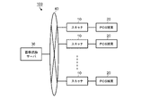
- FIG. 1 is an overall configuration diagram of a code reading system according to one embodiment.
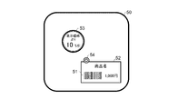
- FIG. 2 is a schematic diagram showing an example of a product according to one embodiment.
- FIG. 3 is a block diagram showing main circuit configurations of a scanner and an image recognition server in the first embodiment.
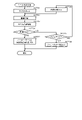
- FIG. 4 is a flowchart showing the main information processing procedures executed by the processor of the scanner according to the code reading program.
- FIG. 5 is a flow chart showing a specific procedure of sticker detection processing in FIG. 4 in the first embodiment.
- FIG. 6 is a block diagram showing main circuit configurations of a scanner and an image recognition server in the second embodiment.
- FIG. 7 is a flow chart showing a specific procedure of sticker detection processing in FIG. 4 in the second embodiment.
- FIG. 8 is a flow chart showing a specific procedure of sticker detection processing in FIG. 4 in the third embodiment.
- the code reading device includes an acquisition unit, a reading unit, a determination unit, a transmission unit, a reception unit, and an output unit.
- the acquisition unit acquires an image of a product captured by an imaging device.
- the reading unit reads a code for obtaining the price of the product from the image of the product acquired by the acquisition unit.
- the determination unit determines whether or not a label displaying price change information related to the price change obtained from the code is attached to the product.
- the transmission unit transmits an image of the product to an image recognition server for recognizing the price change information displayed on the label when it is determined that the label is attached to the product.
- the receiving unit receives the price change information recognized by the image recognition server.
- the output unit outputs the code read by the reading unit to a processing device that processes sales data of the product when it is determined that the label is not attached to the product.
- the output unit outputs the code read by the reading unit and the price change information received by the receiving unit to the processing device when it is determined that the label is attached to the product.
- FIG. 1 is an overall configuration diagram of a code reading system 100 according to an embodiment.
- the code reading system 100 includes multiple scanners 10 , multiple POS (Point Of Sales) terminals 20 , and an image recognition server 30 .
- a plurality of scanners 10 and POS terminals 20 are in one-to-one correspondence, and are connected by communication cables.
- the multiple scanners 10 and the image recognition server 30 are connected to a communication network 40 .
- Communication network 40 is typically a LAN (Local Area Network).
- the LAN may be a wired LAN or a wireless LAN.
- the communication network 40 can be the Internet, and the image recognition server 30 can be a cloud computing server.
- the scanner 10 is an example of a code reading device that reads barcodes from product images captured by an imaging device.
- a bar code is a bar code of a product code that is uniquely set for each product to identify each product, and is usually attached to the case or package of the product.
- the scanner 10 outputs the read barcode data to the POS terminal 20 .
- the scanner 10 may read codes such as two-dimensional data codes or character codes instead of bar codes.
- the POS terminal 20 acquires the product code from the barcode data read by the scanner 10 .
- the POS terminal 20 acquires the price set in the price master in association with the product code, and registers the sales data of the product based on the price.
- a bar code is a code for obtaining the price of a product.
- the POS terminal 20 is an example of a processing device that processes merchandise sales data. Since such a POS terminal 20 is well known, detailed description thereof will be omitted here.
- FIG. 2 is a schematic diagram showing an example of the product 50 according to this embodiment.
- the product 50 is a price change target product that is sold at a 10% discount from the normal price.
- the case or package of the product 50 is provided with a bar code label 52 on which a bar code 51 is displayed together with the product name and normal price.
- the barcode label 52 may be printed on the case or package, or may be attached to the case or package as a sticker label.
- a price change label 53 and a flag sticker 54 are attached to the commodity 50 on the same surface as the bar code label 52 .
- the price change label 53 is attached to the case or package as a sticker label.
- the flag seal 54 is also the same.
- the price change label 53 is a label displaying price change information related to price change.
- Price change label 53 in FIG. 2 displays price change information that discounts the price at a rate of 10%.
- Price change information is not limited to discount rate information. For example, it may be information on a discount amount for discounting the price, selling price information for changing the price to a predetermined selling price, information on a premium rate for increasing the price, and the like.
- the flag sticker 54 indicates that the price change label 53 is attached to the product 50, and is attached to the product 50 in a pair with the price change label 53. At least a portion of the flag seal 54 is applied over the bar code label 52 as shown in FIG.
- the flag seal 54 does not necessarily have to be stuck on top of the bar code label 52 .
- the flag seal 54 may be attached, for example, in contact with the edge of the bar code label 52 . The point is that the flag sticker 54 should be stuck in the vicinity of the bar code label 52 .
- the price change label 53 does not necessarily have to be attached near the bar code label 52 .
- the flag sticker 54 is not attached to the products that are not subject to price change. Basically, only the bar code label 52 is attached to products that are not subject to price change.
- FIG. 3 is a block diagram showing the essential circuit configurations of the scanner 10 and the image recognition server 30. As shown in FIG. 3, only one scanner 10 is shown. Since the other scanners 10 also have the same configuration, description thereof will be omitted here.
- the scanner 10 includes a processor 11, a main memory 12, an auxiliary storage device 13, a timer 14, a communication interface 15, an imaging device 16 and a terminal interface 17.
- the processor 11 , main memory 12 , auxiliary storage device 13 , timer 14 , communication interface 15 , imaging device 16 and terminal interface 17 are connected by a system transmission line 18 .
- the system transmission line 18 includes an address bus, a data bus, control signal lines and the like.
- the scanner 10 constitutes a computer by connecting a processor 11 , a main memory 12 , an auxiliary storage device 13 and a timer 14 via a system transmission line 18 . By connecting the communication interface 15, the imaging device 16, and the terminal interface 17 to this computer, the function as the scanner 10 is realized.
- the processor 11 corresponds to the core part of the above computer.
- the processor 11 controls each part to realize various functions of the scanner 10 according to an operating system or application program.
- the processor 11 includes, for example, a CPU (Central Processing Unit), a GPU (Graphics Processing Unit), an application specific integrated circuit (ASIC)), a programmable logic device (e.g., Simple Programmable Logic Device: SPLD), Complex Programmable Logic Device (CPLD), Field Programmable Gate Array (FPGA)), etc.
- the processor 11 is not limited to being configured as a single processing circuit, and may be configured as the processor 11 by combining a plurality of processing circuits. The same applies to other processors according to this embodiment.
- the main memory 12 may be a volatile memory (random access memory) or a non-volatile memory (read-only memory, non-volatile random access memory).
- the main memory 12 stores an information processing program and data necessary for information processing.
- the processor 11 reads out and executes programs stored in the main memory 12 to realize predetermined functions. Instead of storing the program in the main memory 12, the program may be directly installed in the processor 11. FIG. In this case, the processor 11 implements a predetermined function by reading out and executing a program incorporated therein. Moreover, the predetermined function may be realized not only by the processor 11 executing a program, but also by combining logic circuits. The same applies to other main memories according to this embodiment.
- the auxiliary storage device 13 corresponds to the auxiliary storage part of the computer.
- a well-known storage device such as SSD (Solid State Drive), HDD (Hard Disc Drive) or EEPROM (registered trademark) (Electric Erasable Programmable Read-Only Memory) may be used alone or in combination. Used.
- the auxiliary storage device 13 stores data used by the processor 11 in performing various types of processing, data created by processing in the processor 11, and the like.
- the auxiliary storage device 13 may store the above information processing program.
- the information processing program stored in the main memory 12 or the auxiliary storage device 13 includes a code reading program.
- a method for installing the code reading program in the main memory 12 or the auxiliary storage device 13 is not particularly limited.
- the code reading program can be installed in the main memory 12 or the auxiliary storage device 13 by recording the control program on a removable recording medium or distributing the code reading program by communication via a network.
- the recording medium may be of any form, such as an SD memory card, USB memory, etc., as long as it can store the program and can be read by the device.
- the timer 14 is a device that starts counting time in response to an activation signal and outputs a timeout signal when the counted time reaches a predetermined timeout period.
- the timeout period is the operating time required for the image recognition server 30 to recognize the price change information displayed on the price change label 53 from the product image.
- the communication interface 15 is an interface with the image recognition server 30.
- the communication interface 15 transmits and receives data signals to and from the image recognition server 30 connected via the communication network 40 according to a predetermined communication protocol.
- the imaging device 16 includes a CCD (Charge Coupled Device) imaging element which is an area image sensor, a driving circuit for driving the CCD imaging element, and an image pickup device for forming an image of an imaging area through a reading window on the CCD imaging element. It is a device that has a lens and outputs data of an image formed on a CCD image sensor.
- CCD Charge Coupled Device
- the terminal interface 17 is an interface with the POS terminal 20.
- the terminal interface 17 transmits and receives data signals to and from the POS terminal 20 connected by a communication cable.
- the processor 11 has functions as an acquisition unit 111 , a reading unit 112 , a determination unit 113 , a transmission unit 114 , a reception unit 115 and an output unit 116 .
- the acquisition unit 111 has a function of acquiring an image of the product imaged by the imaging device 16 .
- Acquisition unit 111 can be rephrased as acquisition means.
- the reading unit 112 has a function of reading a code for obtaining the price of the product, that is, the barcode 51 from the image of the product acquired by the acquisition unit 111 .
- An existing technique is used as the technique for reading the barcode 51 from the image.
- the reading unit 112 can be rephrased as reading means.
- the judging unit 113 has a function of judging whether or not a label displaying price change information relating to a price change obtained from the bar code 51, that is, a price change label 53 is attached to the product.
- the determination unit 113 detects the flag sticker 54 attached near the bar code 51, the determination unit 113 determines that the price change label 53 is attached to the product. If the determination unit 113 does not detect the flag sticker 54, the determination unit 113 determines that the price change label 53 is not attached to the product.
- the determination unit 113 can be rephrased as determination means.
- the transmission unit 114 has a function of transmitting the image of the product captured by the imaging device 16 to the image recognition server 30 when the determination unit 113 determines that the price change label 53 is attached to the product.
- the transmission unit 114 can be rephrased as a terminal-side transmission unit or transmission means.
- the receiving unit 115 has a function of receiving price change information recognized by the image recognition server 30 .
- the receiving unit 115 can be rephrased as a terminal-side receiving unit or receiving means.
- the output unit 116 includes the following two functions. The first is a function of outputting the data of the bar code 51 read by the reading unit 112 to the POS terminal 20 when the determination unit 113 determines that the price change label 53 is not attached to the product. Second, when the determining unit 113 determines that the price change label 53 is attached to the product, the data of the bar code 51 read by the reading unit 112 and the price change information received by the receiving unit 115 are read. This function is to output to the POS terminal 20 .
- the output unit 116 can be rephrased as output means.
- the image recognition server 30 comprises a processor 31, a main memory 32, an auxiliary storage device 33 and a communication interface 34.
- the processor 31 , main memory 32 , auxiliary storage device 33 and communication interface 34 are connected by a system transmission line 35 .
- the system transmission line 35 includes an address bus, a data bus, control signal lines and the like.
- the image recognition server 30 constitutes a computer by connecting a processor 31 , a main memory 32 and an auxiliary storage device 33 via a system transmission line 35 . By connecting the communication interface 34 to this computer, the function as the image recognition server 30 is realized.
- the processor 31 corresponds to the core part of the computer.
- the processor 31 controls each part to realize various functions of the image recognition server 30 according to an information processing program.
- the processor 31 is, for example, a CPU.
- the main memory 32 is a volatile memory (random access memory) or a non-volatile memory (read-only memory, non-volatile random access memory).
- the auxiliary storage device 33 corresponds to the auxiliary storage part of the computer.
- a well-known storage device such as SSD, HDD or EEPROM is used singly or in combination.
- the auxiliary storage device 33 stores data used when the processor 31 performs various types of processing, data created by processing in the processor 31, and the like.
- the auxiliary storage device 33 may store the above application programs.
- the communication interface 34 is an interface with each scanner 10 .
- the communication interface 34 transmits and receives data signals to and from each scanner 10 connected via the communication network 40 according to a predetermined communication protocol.
- the processor 31 has functions as a receiving unit 311 , a recognizing unit 312 and a transmitting unit 313 .
- the receiving unit 311 has a function of receiving an image of a product sent from the scanner 10 through the communication network 40 .
- the receiver 311 can be rephrased as a server-side receiver.
- the recognition unit 312 has a function of recognizing the price change information displayed on the price change label 53 from the product image received by the reception unit 311 .
- An existing technology is used as a technology for recognizing price change information from an image.
- the recognition unit 312 can be rephrased as a server-side recognition unit.
- the transmission unit 313 is a function that transmits the price change information recognized by the recognition unit 312 to the scanner 10 that is the transmission source of the recognized image.
- the transmission unit 313 can be rephrased as a server-side transmission unit.
- FIGS. 4 and 5 are flowcharts showing the main information processing procedures executed by the processor 11 of the scanner 10 according to the code reading program. That is, the processor 11 causes the scanner 10 to function as a code reader according to the code reading program. Main operations of the scanner 10 will be described below according to the flow chart. Note that the information processing procedure is not limited to following the flowchart. Any suitable change can be made as long as the same action and effect can be obtained.
- the processor 11 waits for input of a reading start command as ACT1.
- a read start command is given from the corresponding POS terminal 20 .
- the POS terminal 20 when the transaction with the immediately preceding customer is settled, the POS terminal 20 outputs a reading start command to the scanner 10 .
- the processor 11 determines YES in ACT1 and proceeds to ACT2.
- the processor 11 outputs a start signal to the imaging device 16 as ACT2.
- the CCD imaging element is energized. Data of the image formed on the CCD image sensor through the reading window is output to the image memory.
- the image memory is part of the volatile memory area in main memory 12 .
- the processor 11 acquires the image stored in the image memory by the function of the acquisition unit 111 as ACT3. Then, the processor 11 reads the barcode 51 from the image by the function of the reading unit 112 as ACT4. The processor 11 confirms whether or not the bar code 51 has been read as ACT5. If the barcode 51 could not be read from the image, the processor 11 determines NO in ACT5 and returns to ACT3. That is, the processor 11 repeats the process of sequentially fetching images from the image memory and reading the bar code 51 from the images. As a result, if the bar code 51 can be read, the processor 11 determines YES in ACT5 and proceeds to ACT6.
- the processor 11 determines whether or not the price change label 53 is attached to the product by the function of the determination unit 113 in ACT6. Specifically, the processor 11 retrieves the flag sticker 54 from the image in which the barcode 51 has been read. The processor 11 confirms whether or not the flag seal 54 has been detected as ACT7. If the item does not have a price change label 53, the flag seal 54 will not be detected. If the flag seal 54 cannot be detected, the processor 11 determines NO in ACT7 and proceeds to ACT8. The processor 11 outputs the data of the bar code 51 to the POS terminal 20 via the terminal interface 17 by the function of the output unit 116 as ACT8. In principle, the flag sticker 54 is detected when the price change label 53 is attached to the product. If the flag seal 54 can be detected, the processor 11 determines YES in ACT7 and proceeds to ACT9. The processor 11 executes sticker detection processing as ACT9. The sticker detection process will be described later.
- the processor 11 After completing the processing of ACT8 or ACT9, the processor 11 proceeds to ACT10.
- the processor 11 confirms whether or not a reading end command has been input as ACT10.
- a read end command is given from the corresponding POS terminal 20 . For example, when a closing operation is performed at the POS terminal 20 to instruct the end of registration of the product to be purchased by the customer, the POS terminal 20 outputs a reading end command to the scanner 10 . If the read end command has not been input, the processor 11 determines NO in ACT10 and returns to ACT3. The processor 11 executes the processing after ACT3 in the same manner as described above.
- the processor 11 determines YES in ACT10 and proceeds to ACT11.
- the processor 11 outputs a stop signal to the imaging device 16 as ACT11.
- the CCD imaging device is in a non-energized state. With this, the processor 11 completes the information processing of the procedure shown in the flow chart of FIG. The processor 11 again waits for the read start command to be input.
- FIG. 5 is a flow chart showing a specific procedure of sticker detection processing.
- the processor 11 starts the timer 14 as ACT21.
- the processor 11 also uses the function of the transmission unit 114 as the ACT 22 to transmit the data of the image in which the flag sticker 54 is detected to the image recognition server 30 via the communication interface 15 .
- the processor 21 of the image recognition server 30 When the processor 21 of the image recognition server 30 receives the image data via the communication interface 34 by the function of the reception unit 311, the image of the image data is displayed on the price change label 53 by the function of the recognition unit 312. Recognize price change information. Upon recognizing the price change information, the processor 21 uses the function of the transmission unit 313 to transmit a recognition success response command to the scanner 10 that is the source of the image data via the communication interface 34 .
- the recognition success response command includes the price change information that could be recognized.
- the processor 11 of the scanner 10 that has transmitted the image data confirms whether or not a recognition success response command has been received from the image recognition server 30 using the function of the receiving unit 115 as ACT 23 . If no response command has been received, the processor 11 determines NO in ACT23 and proceeds to ACT24. The processor 11 confirms whether the timer 14 has timed out as ACT24. If the timer 14 has not timed out, the processor 11 determines NO in ACT24 and proceeds to ACT25.
- the processor 11 fetches the next image from the image memory as ACT25. Processor 11 then returns to ACT22. That is, processor 11 transmits image data to image recognition server 30 . Then, the processor 11 confirms whether or not a recognition success response command has been received. If no successful recognition response command is received and the timer 14 has not timed out, the processor 11 fetches the next image from the image memory. Then, the processor 11 repeats the processing after ACT22 in the same manner as described above.
- the processor 11 receives a recognition success response command from the image recognition server 30 via the communication interface 15 by the function of the receiving unit 115, and determines YES in ACT 23, Proceed to ACT26.
- the processor 11 uses the function of the output unit 116 as ACT 26 to output the bar code data read in the process of ACT 4 and the price change information included in the recognition success response command to the POS terminal 20 via the terminal interface 17. do.
- the processor 11 determines YES in ACT24 and proceeds to ACT27.
- the processor 11 outputs the bar code data read in the processing of ACT4 to the POS terminal 20 via the terminal interface 17 by the function of the output unit 116 as ACT27.
- processor 11 After finishing the processing of ACT26 or ACT27, the processor 11 ends the sticker detection processing. Processor 11 proceeds to the processing of ACT10 described above.
- the code reading system 100 including the scanner 10 and the image recognition server 30 that operate in this manner can provide the following effects.
- the imaging device 16 of the scanner 10 is activated.
- the operator picks up the products to be purchased by the customer one by one and holds the surface with the bar code label 52 over the reading window of the imaging device 16 .
- the operator may be a store clerk or a customer.
- the scanner 10 When the surface with the barcode label 52 is held over the reading window, the scanner 10 reads the barcode 51 printed on the barcode label 52 . Further, in the scanner 10, it is determined whether or not the flag sticker 54 is attached near the bar code label 52 or not. When the flag sticker 54 is not affixed, that is, when the bar code 51 of the product whose price is not subject to price change is read, the data of the bar code 51 is output from the scanner 10 to the POS terminal 20 . As a result, in the POS terminal 20, product sales data is registered and processed at the price obtained from the data of the bar code 51. FIG.
- the flag sticker 54 is affixed, that is, when the barcode 51 of the product whose price is to be changed is read
- the image captured by the imaging device 16 is transmitted from the scanner 10 to the image recognition server 30. sent.
- the image recognition server 30 recognizes the price change information displayed on the price change label 53 from the image.
- the scanner 10 outputs the data of the bar code 51 and the price change information of the price change label 53 to the POS terminal 20 .
- the product sales data is registered and processed at the price obtained from the data of the bar code 51 changed by the price change information.
- the process of reading the barcode 51 from the image captured by the imaging device 16 is performed by the scanner 10.
- the image recognition server 30 performs the recognition processing of the price change information displayed on the price change label 53 .
- the image transmitted from the scanner 10 to the image recognition server 30 via the communication network 40 is captured by the imaging device 16 after the flag sticker 54 is detected and before the price change information is recognized. This is an image.
- the image in which the flag sticker 54 is detected has a high possibility of including the image of the price change label 53 .
- the transmission of the image ends when the timeout period of the timer 14 elapses after the flag sticker 54 is detected. Therefore, from this point as well, there is an effect that wasteful image transmission can be suppressed.
- the image recognition server 30 recognizes the price change information displayed on the price change label 53. Therefore, even if the format of the price change label 53 is changed, it is only necessary to add a new image recognition algorithm corresponding to the changed format to the image recognition server 30 . Therefore, regardless of the number of scanners 10, there is an advantage that the format change of the price change label 53 can be easily dealt with.
- FIGS. 1, 2 and 4 described in the first embodiment are commonly used in the second embodiment as well. Therefore, description thereof is omitted.
- FIG. 6 is a block diagram showing main circuit configurations of the scanner 10 and the image recognition server 30 in the second embodiment.
- the parts common to those in FIG. 3 showing the same block diagram of the first embodiment are denoted by the same reference numerals.
- the second embodiment differs from the first embodiment in that the processor 11 of the scanner 10 has a function as a recognition unit 117. is.
- the recognition unit 117 has a function of recognizing price change information displayed on the price change label 53 from the product image.
- An existing technology is used as a technology for recognizing price change information from an image.
- the recognition unit 117 can be rephrased as a device-side recognition unit.
- FIG. 7 is a flow chart showing a specific procedure of sticker detection processing.
- part of the sticker detection process indicated by ACT9 in FIG. 4 is different from that in the first embodiment.
- the processor 11 when entering the seal detection process, the processor 11 starts the timer 14 as ACT31. Then, the processor 11 uses the function of the transmission unit 114 as the ACT 32 to transmit the data of the image in which the flag sticker 54 is detected to the image recognition server 30 via the communication interface 15 . Further, the processor 11 recognizes the price change information displayed on the price change label 53 from the image in which the flag sticker 54 is detected by the function of the recognition unit 117 as ACT 33 .
- the function of the recognition unit 312 recognizes the price from the image of the image data. Recognize price change information displayed on change label 53 .
- the processor 21 uses the function of the transmission unit 313 to transmit a recognition success response command to the scanner 10 that is the source of the image data via the communication interface 34 .
- the recognition success response command includes the recognized price change information.
- the processor 11 After completing the processing of ACT32 and ACT33, the processor 11 checks in ACT34 whether or not the price change information has been successfully recognized. If the recognition is not successful, the processor 11 determines NO in ACT34 and proceeds to ACT35. The processor 11 checks in ACT 35 whether or not the timer 14 has timed out. If the timer 14 has not timed out, the processor 11 determines NO in ACT35 and proceeds to ACT36.
- the processor 11 fetches the next image from the image memory as ACT36. Processor 11 then returns to ACT32. That is, processor 11 transmits image data to image recognition server 30 . Processor 11 also recognizes price change information displayed on price change label 53 from the image. The processor 11 then confirms whether or not the price change information has been successfully recognized. If price change information is not successfully recognized and timer 14 has not timed out, processor 11 fetches the next image from image memory. Then, the processor 11 repeats the processing after ACT32 in the same manner as described above.
- the processor 11 determines YES in ACT34, and proceeds to ACT37. move on.
- the processor 11 uses the function of the output unit 116 as ACT 37 to output the bar code data read in the process of ACT 4 and the successfully recognized price change information to the POS terminal 20 via the terminal interface 17 .
- the processor 11 determines YES in ACT35. and proceed to ACT38.
- the processor 11 uses the function of the output unit 116 as ACT 38 to output the bar code data read in the process of ACT 4 to the POS terminal 20 via the terminal interface 17 .
- Processor 11 After finishing the processing of ACT37 or ACT38, the processor 11 ends the sticker detection processing. Processor 11 proceeds to process ACT 10 in FIG.
- the transmission unit The image is transmitted to the image recognition server 30 by the function of 114 . Further, the scanner 10 recognizes the price change information displayed on the price change label 53 from the image by the function of the recognition section 117 .
- the scanner 10 outputs the data of the bar code 51 and the price change information to the POS terminal 20 by the function of the output unit 116 . Even if the recognition unit 117 cannot recognize the price change information, when the price change information recognized by the image recognition server 30 is received by the function of the reception unit 115, the data of the bar code 51 and the data of the bar code 51 are processed by the function of the output unit 116. price change information to the POS terminal 20.
- the bar code 51 Merchandise sales data is registered and processed at a price obtained from the data and changed by the price change information.
- the image in which the flag sticker 54 is detected contains the image of the price change label 53. Therefore, if the format of the price change label 53 corresponds to the image recognition algorithm prepared by the scanner 10, there is a high possibility that the recognition unit 117 will recognize the price change information first. That is, since there is no need to wait for the price change information to be recognized by the image recognition server 30, the processing efficiency of product registration can be improved. Further, when the price change information is first recognized by the recognition unit 117 before the timer 14 times out, the image after that is not transmitted to the image recognition server 30, so the communication network is more efficient than the first embodiment. There is an advantage that the amount of data communication of 40 can be reduced.
- the image recognition server 30 prepares the algorithm so that the price change information can be reliably recognized. can do. Therefore, even if the format of the price change label 53 is changed, it can be dealt with without changing the algorithm on the scanner 10 side.
- FIGS. 1, 2 and 4 described in the first embodiment and FIG. 6 described in the second embodiment are commonly used in the third embodiment. Therefore, description thereof is omitted.
- FIG. 8 is a flow chart showing a specific procedure of sticker detection processing.
- the third embodiment also differs from the first or second embodiment in part of the sticker detection process indicated by ACT9 in FIG.
- the processor 11 when entering the seal detection process, the processor 11 recognizes the price change information displayed on the price change label 53 from the image in which the flag sticker 54 is detected by the function of the recognition unit 117 as ACT 41. do.
- the image in which the flag sticker 54 is detected has a high possibility of including the image of the price change label 53 . Therefore, if the format of the price change label 53 corresponds to the image recognition algorithm prepared by the scanner 10, there is a high possibility that the recognition unit 117 will recognize the price change information from the image.
- the processor 11 confirms as ACT 42 whether or not the price change information has been successfully recognized. If the price change information is successfully recognized, processor 11 determines YES in ACT 42 and proceeds to ACT 48 .
- the processor 11 uses the function of the output unit 116 as ACT 48 to output the bar code data read in the process of ACT 4 and the successfully recognized price change information to the POS terminal 20 via the terminal interface 17 .
- the processor 11 ends the sticker detection process and proceeds to the process of ACT10 in FIG.
- the recognition unit 117 cannot recognize the price change information from the image.
- the processor 11 determines NO in ACT42 and proceeds to ACT43. Thereafter, the processor 11 executes the same processes as ACT22 to ACT27 described in the first embodiment as ACT43 to ACT49.
- the recognition unit The function 117 recognizes the price change information displayed on the price change label 53 from the image. Then, when the price change information can be recognized, the scanner 10 outputs the data of the bar code 51 and the price change information to the POS terminal 20 by the function of the output unit 116 .
- the scanner 10 transmits the image to the image recognition server 30 using the function of the transmission unit 114 .
- the scanner 10 receives the price change information recognized by the image recognition server 30 by the function of the receiving unit 115, the scanner 10 outputs the data of the bar code 51 and the price change information to the POS terminal 20 by the function of the output unit 116. .
- the image in which the flag sticker 54 is detected contains the image of the price change label 53. Therefore, when the format of the price change label 53 corresponds to the image recognition algorithm prepared by the scanner 10, the frequency of image transmission from the scanner 10 to the image recognition server 30 is the first or the first. significantly reduced compared to the second embodiment. As a result, there is an advantage that the amount of data communication in the communication network 40 can be reduced more than in the first or second embodiment. Further, it goes without saying that a change in the format of the price change label 53 can be dealt with without changing the algorithm on the scanner 10 side.
- the scanner 10 and the POS terminal 20 are connected by a communication cable.
- a device in which the scanner 10 and the POS terminal 20 are integrated, for example, a self-service checkout terminal may be used as an aspect of the code reading device.
- the scanner 10 may be equipped with devices such as a keyboard, a touch panel, and a display, and may be compatible with the registration of products such as perishables that do not have barcodes.
- the image acquired by the acquisition unit 111 is transmitted to the image recognition server 30 by the function of the transmission unit 114 .
- the price change information recognized by the image recognition server 30 is received by the function of the receiving unit 115, the price change information is sent to the POS terminal 20 together with the code of the product without the barcode by the function of the output unit 116. output. Even if such a configuration is adopted, it is possible to reduce the amount of data communication on the communication network 40, and it is possible to easily cope with the change in the format of the price change label 53.
- the image recognized by the image recognition server 30 is not limited to the price change information displayed on the price change label 53 .
- the image recognized by the image recognition server 30 is information of the expiration date displayed on the label.
- the expiration date information is also information that changes the price as a result, it can be rephrased as price change information.
- the program according to the present embodiment may be transferred while stored in the electronic device, or may be transferred without being stored in the electronic device. In the latter case, the program may be transferred via a network, or may be transferred while being recorded on a recording medium.
- a recording medium is a non-transitory tangible medium.
- the recording medium is a computer-readable medium.
- the recording medium may be a medium such as a CD-ROM, a memory card, etc., which can store a program and is readable by a computer, and its form is not limited.
Landscapes
- Physics & Mathematics (AREA)
- Engineering & Computer Science (AREA)
- General Physics & Mathematics (AREA)
- Business, Economics & Management (AREA)
- Theoretical Computer Science (AREA)
- Accounting & Taxation (AREA)
- Toxicology (AREA)
- Health & Medical Sciences (AREA)
- Electromagnetism (AREA)
- General Health & Medical Sciences (AREA)
- Artificial Intelligence (AREA)
- Computer Vision & Pattern Recognition (AREA)
- Finance (AREA)
- General Business, Economics & Management (AREA)
- Strategic Management (AREA)
- General Engineering & Computer Science (AREA)
- Cash Registers Or Receiving Machines (AREA)
Abstract
Description
[第1の実施形態]
はじめに、第1の実施形態について、図1乃至図5を用いて説明する。
商品に価格変更ラベル53が付されていない場合、フラグシール54は検出されない。フラグシール54を検出できない場合、プロセッサ11は、ACT7においてNOと判定し、ACT8へと進む。プロセッサ11は、ACT8として出力部116の機能により端末インターフェース17を介してバーコード51のデータをPOS端末20へと出力する。
商品に価格変更ラベル53が付されている場合には、原則、フラグシール54が検出される。フラグシール54を検出できた場合には、プロセッサ11は、ACT7においてYESと判定し、ACT9へと進む。プロセッサ11は、ACT9としてシール検出処理を実行する。シール検出処理については後述する。
次に、第2の実施形態について、図6及び図7を用いて説明する。因みに、第1の実施形態で説明した図1、図2及び図4については第2の実施形態においても共通に使用される。よって、その説明は省略する。
したがってPOS端末20においては、画像認識サーバ30の認識部312で価格変更情報が認識された場合だけでなく、スキャナ10の認識部117で価格変更情報が認識された場合においても、バーコード51のデータから得られる価格を価格変更情報で変更した価格で商品販売データが登録処理される。
次に、第3の実施形態について、図8を用いて説明する。因みに、第1の実施形態で説明した図1、図2及び図4と、第2の実施形態で説明した図6は、第3の実施形態においても共通に使用される。よって、その説明は省略する。
本実施形態に係るプログラムは、電子機器に記憶された状態で譲渡されてよいし、電子機器に記憶されていない状態で譲渡されてもよい。後者の場合は、プログラムは、ネットワークを介して譲渡されてよいし、記録媒体に記録された状態で譲渡されてもよい。記録媒体は、非一時的な有形の媒体である。記録媒体は、コンピュータ可読媒体である。記録媒体は、CD-ROM、メモリカード等のプログラムを記憶可能かつコンピュータで読取可能な媒体であればよく、その形態は問わない。
Claims (12)
- 撮像装置で撮像された商品の画像を取得する取得部と、
前記取得部で取得した前記商品の画像から、当該商品の価格を得るためのコードを読み取る読取部と、
前記コードにより得られる前記価格の変更に係る価格変更情報を表示したラベルが前記商品に付されているか否かを判定する判定部と、
前記判定部で前記ラベルが前記商品に付されていると判定された場合、前記商品の画像を、前記ラベルに表示されている前記価格変更情報を認識するための画像認識サーバに送信する送信部と、
前記画像認識サーバで認識された前記価格変更情報を受信する受信部と、
前記判定部で前記ラベルが前記商品に付されていないと判定された場合には、前記読取部で読み取ったコードを、前記商品の販売データを処理する処理装置に出力し、前記ラベルが前記商品に付されていると判定された場合には、前記読取部で読み取ったコードと前記受信部で受信した前記価格変更情報とを前記処理装置に出力する出力部と、
を具備するコード読取装置。 - 前記ラベルに表示されている前記価格変更情報を認識する認識部、
をさらに具備し、
前記判定部で前記ラベルが前記商品に付されていると判定された場合、前記出力部は、前記受信部で前記価格変更情報を受信する前に前記認識部で前記価格変更情報が認識された場合には、前記読取部で読み取ったコードと前記認識部で認識された前記価格変更情報とを前記処理装置に出力し、前記認識部で前記価格変更情報が認識される前に前記受信部で前記価格変更情報を受信した場合には、前記読取部で読み取ったコードと前記受信部で受信した前記価格変更情報とを前記処理装置に出力する、請求項1記載のコード読取装置。 - 前記ラベルに表示されている前記価格変更情報を認識する認識部、
をさらに具備し、
前記送信部は、前記判定部で前記ラベルが前記商品に付されていると判定され、かつ、前記認識部で前記価格変更情報が認識されない場合に、前記商品の画像を前記画像認識サーバに送信し、
前記判定部で前記ラベルが前記商品に付されていると判定された場合、前記出力部は、前記認識部で前記価格変更情報が認識された場合には、前記読取部で読み取ったコードと前記認識部で認識された前記価格変更情報とを前記処理装置に出力し、前記認識部で前記価格変更情報が認識されなかった場合には、前記読取部で読み取ったコードと前記受信部で受信した前記価格変更情報とを前記処理装置に出力する、請求項1記載のコード読取装置。 - 複数のコード読取装置と、画像認識サーバとを備え、
前記複数のコード読取装置は、
撮像装置で撮像された商品の画像を取得する取得部と、
前記取得部で取得した前記商品の画像から、当該商品の価格を得るためのコードを読み取る読取部と、
前記コードにより得られる前記価格の変更に係る価格変更情報を表示したラベルが前記商品に付されているか否かを判定する判定部と、
前記判定部で前記ラベルが前記商品に付されていると判定された場合、前記商品の画像を前記画像認識サーバに送信する装置側送信部と、
前記画像認識サーバで認識された前記価格変更情報を受信する装置側受信部と、
前記判定部で前記ラベルが前記商品に付されていないと判定された場合には、前記読取部で読み取ったコードを、前記商品の販売データを処理する処理装置に出力し、前記ラベルが前記商品に付されていると判定された場合には、前記読取部で読み取ったコードと前記装置側受信部で受信した前記価格変更情報とを前記処理装置に出力する出力部と、をそれぞれ具備し、
前記画像認識サーバは、
前記コード読取装置から前記商品の画像を受信するサーバ側受信部と、
前記サーバ側受信部で受信した前記商品の画像から前記価格変更情報を認識するサーバ側認識部と、
前記サーバ側認識部で認識された前記価格変更情報を前記画像の送信元である前記コード読取装置へと送信するサーバ側送信部と、
を具備するコード読取システム。 - 前記コード読取装置は、
前記ラベルに表示されている前記価格変更情報を認識する装置側認識部、
をさらに具備し、
前記判定部で前記ラベルが前記商品に付されていると判定された場合、前記出力部は、前記装置側受信部で前記価格変更情報を受信する前に前記装置側認識部で前記価格変更情報が認識された場合には、前記読取部で読み取ったコードと前記装置側認識部で認識された前記価格変更情報とを前記処理装置に出力し、前記装置側認識部で前記価格変更情報が認識される前に前記装置側受信部で前記価格変更情報を受信した場合には、前記読取部で読み取ったコードと前記装置側受信部で受信した前記価格変更情報とを前記処理装置に出力する、請求項4記載のコード読取システム。 - 前記コード読取装置は、
前記ラベルに表示されている前記価格変更情報を認識する装置側認識部、
をさらに具備し、
前記装置側送信部は、前記判定部で前記ラベルが前記商品に付されていると判定され、かつ、前記装置側認識部で前記価格変更情報が認識されない場合に、前記商品の画像を前記画像認識サーバに送信し、
前記判定部で前記ラベルが前記商品に付されていると判定された場合、前記出力部は、前記装置側認識部で前記価格変更情報が認識された場合には、前記読取部で読み取ったコードと前記装置側認識部で認識した前記価格変更情報とを前記処理装置に出力し、前記装置側認識部で前記価格変更情報が認識されなかった場合には、前記読取部で読み取ったコードと前記装置側受信部で受信した前記価格変更情報とを前記処理装置に出力する、請求項4記載のコード読取システム。 - コード読取装置のコンピュータに、
撮像装置で撮像された商品の画像を取得することと、
前記商品の画像から、当該商品の価格を得るためのコードを読み取ることと、
前記コードにより得られる前記価格の変更に係る価格変更情報を表示したラベルが前記商品に付されているか否かを判定することと、
前記ラベルが前記商品に付されていると判定された場合、前記商品の画像を、前記ラベルに表示されている前記価格変更情報を認識するための画像認識サーバに送信することと、
前記画像認識サーバで認識された前記価格変更情報を受信することと、及び、
前記ラベルが前記商品に付されていないと判定された場合には、読み取ったコードを、前記商品の販売データを処理する処理装置に出力し、前記ラベルが前記商品に付されていると判定された場合には、読み取ったコードと受信した前記価格変更情報とを前記処理装置に出力することと、
を実行させるプログラムを記録したプログラム記録媒体。 - 前記コンピュータに、
前記ラベルに表示されている前記価格変更情報を認識部で認識することと、
前記ラベルが前記商品に付されていると判定され、かつ、前記価格変更情報を受信する前に前記価格変更情報が前記認識部で認識された場合には、読み取ったコードと前記認識部で認識された前記価格変更情報とを前記処理装置に出力し、前記ラベルが前記商品に付されていると判定され、かつ、前記価格変更情報が前記認識部で認識される前に前記価格変更情報を受信した場合には、読み取ったコードと受信した前記価格変更情報とを前記処理装置に出力することと、
を実行させるプログラムを記録した請求項7記載のプログラム記録媒体。 - 前記コンピュータに、
前記ラベルに表示されている前記価格変更情報を認識部で認識することと、
前記ラベルが前記商品に付されていると判定され、かつ、前記価格変更情報が前記認識部で認識されない場合に、前記商品の画像を前記画像認識サーバに送信することと、
前記ラベルが前記商品に付されていると判定され、かつ、前記価格変更情報が前記認識部で認識された場合には、読み取ったコードと前記認識部で認識された前記価格変更情報とを前記処理装置に出力し、前記価格変更情報が前記認識部で認識されなかった場合には、読み取ったコードと受信した前記価格変更情報とを前記処理装置に出力することと、
を実行させるプログラムを記録した請求項7記載のプログラム記録媒体。 - 取得部が、撮像装置で撮像された商品の画像を取得することと、
前記取得部で取得した前記商品の画像から、読取部が、当該商品の価格を得るためのコードを読み取り、判定部が、前記コードにより得られる前記価格の変更に係る価格変更情報を表示したラベルが前記商品に付されているか否かを判定することと、
前記ラベルが前記商品に付されていないと判定された場合、出力部が、前記読取部で読み取ったコードを、前記商品の販売データを処理する処理装置に出力することと、
前記ラベルが前記商品に付されていると判定された場合、送信部が、前記商品の画像を、前記ラベルに表示されている前記価格変更情報を認識するための画像認識サーバに送信し、受信部が、前記画像認識サーバで認識された前記価格変更情報を受信すると、前記出力部が、前記読取部で読み取ったコードと前記受信部で受信した前記価格変更情報とを前記処理装置に出力することと、を具備するコード読取方法。 - 前記ラベルが前記商品に付されていると判定された場合、認識部が、前記ラベルに表示されている前記価格変更情報を認識するとともに、送信部が、前記商品の画像を前記画像認識サーバに送信することと、
前記出力部は、前記受信部で前記価格変更情報を受信する前に前記認識部で前記価格変更情報が認識された場合には、前記読取部で読み取ったコードと前記認識部で認識した前記価格変更情報とを前記処理装置に出力し、前記認識部で前記価格変更情報を認識する前に前記受信部で前記価格変更情報を受信した場合には、前記読取部で読み取ったコードと前記受信部で受信した前記価格変更情報とを前記処理装置に出力することと、を具備する請求項10記載のコード読取方法。 - 前記ラベルが前記商品に付されていると判定された場合、認識部が、前記ラベルに表示されている前記価格変更情報を認識することと、
前記認識部で前記価格変更情報が認識されない場合、前記送信部が、前記商品の画像を前記画像認識サーバに送信することと、
前記ラベルが前記商品に付されていると判定された場合、前記出力部は、前記認識部で前記価格変更情報が認識された場合には、前記読取部で読み取ったコードと前記認識部で認識された前記価格変更情報とを前記処理装置に出力し、前記認識部で前記価格変更情報が認識されなかった場合には、前記読取部で読み取ったコードと前記受信部で受信した前記価格変更情報とを前記処理装置に出力することと、を具備する請求項10記載のコード読取方法。
Priority Applications (4)
| Application Number | Priority Date | Filing Date | Title |
|---|---|---|---|
| EP22766785.4A EP4307263A4 (en) | 2021-03-10 | 2022-02-18 | CODE READING DEVICE, PROGRAM RECORDING MEDIUM, CODE READING SYSTEM, AND CODE READING METHOD |
| CN202280007981.5A CN116868242B (zh) | 2021-03-10 | 2022-02-18 | 代码读取装置、程序存储介质、代码读取系统及方法 |
| KR1020237019291A KR102794647B1 (ko) | 2021-03-10 | 2022-02-18 | 코드 판독 장치, 프로그램 기록 매체, 코드 판독 시스템 및 코드 판독 방법 |
| US18/330,172 US12153996B2 (en) | 2021-03-10 | 2023-06-06 | Code reading device, program recording medium, code reading system, and code reading method |
Applications Claiming Priority (2)
| Application Number | Priority Date | Filing Date | Title |
|---|---|---|---|
| JP2021038387A JP7585099B2 (ja) | 2021-03-10 | 2021-03-10 | コード読取装置及びそのプログラム、コード読取システム並びにコード読取方法 |
| JP2021-038387 | 2021-03-10 |
Related Child Applications (1)
| Application Number | Title | Priority Date | Filing Date |
|---|---|---|---|
| US18/330,172 Continuation US12153996B2 (en) | 2021-03-10 | 2023-06-06 | Code reading device, program recording medium, code reading system, and code reading method |
Publications (1)
| Publication Number | Publication Date |
|---|---|
| WO2022190822A1 true WO2022190822A1 (ja) | 2022-09-15 |
Family
ID=83227690
Family Applications (1)
| Application Number | Title | Priority Date | Filing Date |
|---|---|---|---|
| PCT/JP2022/006700 Ceased WO2022190822A1 (ja) | 2021-03-10 | 2022-02-18 | コード読取装置、プログラム記録媒体、コード読取システム及びコード読取方法 |
Country Status (5)
| Country | Link |
|---|---|
| US (1) | US12153996B2 (ja) |
| EP (1) | EP4307263A4 (ja) |
| JP (1) | JP7585099B2 (ja) |
| KR (1) | KR102794647B1 (ja) |
| WO (1) | WO2022190822A1 (ja) |
Cited By (1)
| Publication number | Priority date | Publication date | Assignee | Title |
|---|---|---|---|---|
| JP2025053941A (ja) * | 2023-09-26 | 2025-04-07 | 東芝テック株式会社 | 情報処理装置およびプログラム |
Families Citing this family (1)
| Publication number | Priority date | Publication date | Assignee | Title |
|---|---|---|---|---|
| US12026583B2 (en) | 2022-06-22 | 2024-07-02 | Hand Held Products, Inc. | One sensor near far solution to minimize FOV mismatch and aiming offsets |
Citations (5)
| Publication number | Priority date | Publication date | Assignee | Title |
|---|---|---|---|---|
| JP3047598U (ja) * | 1997-09-30 | 1998-04-14 | 株式会社寺岡精工 | 値引きマーク検出装置 |
| JP2012119005A (ja) * | 2008-04-08 | 2012-06-21 | Toshiba Tec Corp | スキャナ装置及びそのスキャナ方法 |
| WO2015147329A1 (ja) * | 2014-03-27 | 2015-10-01 | 日本電気株式会社 | Pos端末装置、情報処理装置、情報処理システム、画像認識方法および画像認識プログラム |
| WO2016002696A1 (ja) * | 2014-07-01 | 2016-01-07 | 日本電気株式会社 | 情報処理装置、情報処理方法、及びプログラム |
| JP2019091501A (ja) | 2012-01-31 | 2019-06-13 | 東芝テック株式会社 | 情報検出装置及び情報検出プログラム |
Family Cites Families (3)
| Publication number | Priority date | Publication date | Assignee | Title |
|---|---|---|---|---|
| US20010054005A1 (en) * | 1995-03-24 | 2001-12-20 | Hook Christopher D. | Programmable shelf tag and method for changing and updating shelf tag information |
| US8042740B2 (en) * | 2000-11-24 | 2011-10-25 | Metrologic Instruments, Inc. | Method of reading bar code symbols on objects at a point-of-sale station by passing said objects through a complex of stationary coplanar illumination and imaging planes projected into a 3D imaging volume |
| JP5788928B2 (ja) * | 2013-03-04 | 2015-10-07 | 東芝テック株式会社 | 情報処理装置及びプログラム |
-
2021
- 2021-03-10 JP JP2021038387A patent/JP7585099B2/ja active Active
-
2022
- 2022-02-18 KR KR1020237019291A patent/KR102794647B1/ko active Active
- 2022-02-18 EP EP22766785.4A patent/EP4307263A4/en active Pending
- 2022-02-18 WO PCT/JP2022/006700 patent/WO2022190822A1/ja not_active Ceased
-
2023
- 2023-06-06 US US18/330,172 patent/US12153996B2/en active Active
Patent Citations (5)
| Publication number | Priority date | Publication date | Assignee | Title |
|---|---|---|---|---|
| JP3047598U (ja) * | 1997-09-30 | 1998-04-14 | 株式会社寺岡精工 | 値引きマーク検出装置 |
| JP2012119005A (ja) * | 2008-04-08 | 2012-06-21 | Toshiba Tec Corp | スキャナ装置及びそのスキャナ方法 |
| JP2019091501A (ja) | 2012-01-31 | 2019-06-13 | 東芝テック株式会社 | 情報検出装置及び情報検出プログラム |
| WO2015147329A1 (ja) * | 2014-03-27 | 2015-10-01 | 日本電気株式会社 | Pos端末装置、情報処理装置、情報処理システム、画像認識方法および画像認識プログラム |
| WO2016002696A1 (ja) * | 2014-07-01 | 2016-01-07 | 日本電気株式会社 | 情報処理装置、情報処理方法、及びプログラム |
Non-Patent Citations (1)
| Title |
|---|
| See also references of EP4307263A4 |
Cited By (1)
| Publication number | Priority date | Publication date | Assignee | Title |
|---|---|---|---|---|
| JP2025053941A (ja) * | 2023-09-26 | 2025-04-07 | 東芝テック株式会社 | 情報処理装置およびプログラム |
Also Published As
| Publication number | Publication date |
|---|---|
| EP4307263A4 (en) | 2024-08-07 |
| KR102794647B1 (ko) | 2025-04-15 |
| US12153996B2 (en) | 2024-11-26 |
| CN116868242A (zh) | 2023-10-10 |
| US20230316023A1 (en) | 2023-10-05 |
| KR20230104268A (ko) | 2023-07-07 |
| JP2022138482A (ja) | 2022-09-26 |
| EP4307263A1 (en) | 2024-01-17 |
| JP7585099B2 (ja) | 2024-11-18 |
Similar Documents
| Publication | Publication Date | Title |
|---|---|---|
| US8505817B2 (en) | Code reading apparatus and code reading method | |
| JP5048161B2 (ja) | スキャナ装置及びそのスキャナ方法 | |
| US10332078B2 (en) | Electronic receipt issuing system | |
| US20130054344A1 (en) | Code reading apparatus, sales data processing apparatus and sales data processing method | |
| US12153996B2 (en) | Code reading device, program recording medium, code reading system, and code reading method | |
| JP7587447B2 (ja) | 読取装置および読取方法 | |
| EP3432238A1 (en) | Data processing apparatus and method, and non-transitory computer readable medium | |
| US20210012305A1 (en) | Settlement system, settlement method, and non-transitory storage medium | |
| US11250405B2 (en) | Commodity sales data processing apparatus with multiple tag readers | |
| CN116868242B (zh) | 代码读取装置、程序存储介质、代码读取系统及方法 | |
| EP2447921A1 (en) | Point of sale terminal | |
| US12182650B2 (en) | Reading apparatus and reading method | |
| US9471823B1 (en) | Multiple barcode processing apparatus, systems, and methods | |
| US20110315764A1 (en) | Code reading apparatus and code reading method | |
| US20230032834A1 (en) | Sales data processing system and method | |
| JP7419084B2 (ja) | リーダ、方法、プログラム | |
| WO2016002697A1 (ja) | 情報処理装置、情報処理方法、およびプログラム | |
| US20220284411A1 (en) | Settlement device and program | |
| US20260087911A1 (en) | Retail transaction processing system with detection apparatus | |
| JP2021039496A (ja) | 情報処理装置、プログラム及びシステム | |
| US12406246B2 (en) | Information processing device and method | |
| US20240095706A1 (en) | Point-of-sale system | |
| JP2005309497A (ja) | 商品販売データ処理装置 | |
| US20220405763A1 (en) | Customer identification server, customer identification system, and customer identification program | |
| JP2024014471A (ja) | 入力装置、取引処理システム及び情報処理プログラム |
Legal Events
| Date | Code | Title | Description |
|---|---|---|---|
| 121 | Ep: the epo has been informed by wipo that ep was designated in this application |
Ref document number: 22766785 Country of ref document: EP Kind code of ref document: A1 |
|
| WWE | Wipo information: entry into national phase |
Ref document number: 202280007981.5 Country of ref document: CN |
|
| ENP | Entry into the national phase |
Ref document number: 20237019291 Country of ref document: KR Kind code of ref document: A |
|
| WWE | Wipo information: entry into national phase |
Ref document number: 202347039151 Country of ref document: IN |
|
| WWE | Wipo information: entry into national phase |
Ref document number: 2301003493 Country of ref document: TH |
|
| WWE | Wipo information: entry into national phase |
Ref document number: 2022766785 Country of ref document: EP |
|
| NENP | Non-entry into the national phase |
Ref country code: DE |
|
| ENP | Entry into the national phase |
Ref document number: 2022766785 Country of ref document: EP Effective date: 20231010 |