WO2022190312A1 - 賦形方法および賦形装置 - Google Patents
賦形方法および賦形装置 Download PDFInfo
- Publication number
- WO2022190312A1 WO2022190312A1 PCT/JP2021/009781 JP2021009781W WO2022190312A1 WO 2022190312 A1 WO2022190312 A1 WO 2022190312A1 JP 2021009781 W JP2021009781 W JP 2021009781W WO 2022190312 A1 WO2022190312 A1 WO 2022190312A1
- Authority
- WO
- WIPO (PCT)
- Prior art keywords
- shaping
- laminate
- predetermined direction
- sheet
- shape
- Prior art date
- Legal status (The legal status is an assumption and is not a legal conclusion. Google has not performed a legal analysis and makes no representation as to the accuracy of the status listed.)
- Ceased
Links
Images


Classifications
-
- B—PERFORMING OPERATIONS; TRANSPORTING
- B29—WORKING OF PLASTICS; WORKING OF SUBSTANCES IN A PLASTIC STATE IN GENERAL
- B29C—SHAPING OR JOINING OF PLASTICS; SHAPING OF MATERIAL IN A PLASTIC STATE, NOT OTHERWISE PROVIDED FOR; AFTER-TREATMENT OF THE SHAPED PRODUCTS, e.g. REPAIRING
- B29C70/00—Shaping composites, i.e. plastics material comprising reinforcements, fillers or preformed parts, e.g. inserts
- B29C70/04—Shaping composites, i.e. plastics material comprising reinforcements, fillers or preformed parts, e.g. inserts comprising reinforcements only, e.g. self-reinforcing plastics
- B29C70/28—Shaping operations therefor
- B29C70/54—Component parts, details or accessories; Auxiliary operations, e.g. feeding or storage of prepregs or SMC after impregnation or during ageing
- B29C70/541—Positioning reinforcements in a mould, e.g. using clamping means for the reinforcement
-
- B—PERFORMING OPERATIONS; TRANSPORTING
- B29—WORKING OF PLASTICS; WORKING OF SUBSTANCES IN A PLASTIC STATE IN GENERAL
- B29C—SHAPING OR JOINING OF PLASTICS; SHAPING OF MATERIAL IN A PLASTIC STATE, NOT OTHERWISE PROVIDED FOR; AFTER-TREATMENT OF THE SHAPED PRODUCTS, e.g. REPAIRING
- B29C70/00—Shaping composites, i.e. plastics material comprising reinforcements, fillers or preformed parts, e.g. inserts
- B29C70/04—Shaping composites, i.e. plastics material comprising reinforcements, fillers or preformed parts, e.g. inserts comprising reinforcements only, e.g. self-reinforcing plastics
- B29C70/28—Shaping operations therefor
- B29C70/54—Component parts, details or accessories; Auxiliary operations, e.g. feeding or storage of prepregs or SMC after impregnation or during ageing
- B29C70/543—Fixing the position or configuration of fibrous reinforcements before or during moulding
-
- B—PERFORMING OPERATIONS; TRANSPORTING
- B29—WORKING OF PLASTICS; WORKING OF SUBSTANCES IN A PLASTIC STATE IN GENERAL
- B29C—SHAPING OR JOINING OF PLASTICS; SHAPING OF MATERIAL IN A PLASTIC STATE, NOT OTHERWISE PROVIDED FOR; AFTER-TREATMENT OF THE SHAPED PRODUCTS, e.g. REPAIRING
- B29C70/00—Shaping composites, i.e. plastics material comprising reinforcements, fillers or preformed parts, e.g. inserts
- B29C70/04—Shaping composites, i.e. plastics material comprising reinforcements, fillers or preformed parts, e.g. inserts comprising reinforcements only, e.g. self-reinforcing plastics
- B29C70/28—Shaping operations therefor
- B29C70/30—Shaping by lay-up, i.e. applying fibres, tape or broadsheet on a mould, former or core; Shaping by spray-up, i.e. spraying of fibres on a mould, former or core
- B29C70/34—Shaping by lay-up, i.e. applying fibres, tape or broadsheet on a mould, former or core; Shaping by spray-up, i.e. spraying of fibres on a mould, former or core and shaping or impregnating by compression, i.e. combined with compressing after the lay-up operation
-
- B—PERFORMING OPERATIONS; TRANSPORTING
- B29—WORKING OF PLASTICS; WORKING OF SUBSTANCES IN A PLASTIC STATE IN GENERAL
- B29C—SHAPING OR JOINING OF PLASTICS; SHAPING OF MATERIAL IN A PLASTIC STATE, NOT OTHERWISE PROVIDED FOR; AFTER-TREATMENT OF THE SHAPED PRODUCTS, e.g. REPAIRING
- B29C70/00—Shaping composites, i.e. plastics material comprising reinforcements, fillers or preformed parts, e.g. inserts
- B29C70/04—Shaping composites, i.e. plastics material comprising reinforcements, fillers or preformed parts, e.g. inserts comprising reinforcements only, e.g. self-reinforcing plastics
- B29C70/28—Shaping operations therefor
- B29C70/54—Component parts, details or accessories; Auxiliary operations, e.g. feeding or storage of prepregs or SMC after impregnation or during ageing
- B29C70/545—Perforating, cutting or machining during or after moulding
-
- B—PERFORMING OPERATIONS; TRANSPORTING
- B29—WORKING OF PLASTICS; WORKING OF SUBSTANCES IN A PLASTIC STATE IN GENERAL
- B29C—SHAPING OR JOINING OF PLASTICS; SHAPING OF MATERIAL IN A PLASTIC STATE, NOT OTHERWISE PROVIDED FOR; AFTER-TREATMENT OF THE SHAPED PRODUCTS, e.g. REPAIRING
- B29C2793/00—Shaping techniques involving a cutting or machining operation
- B29C2793/009—Shaping techniques involving a cutting or machining operation after shaping
-
- B—PERFORMING OPERATIONS; TRANSPORTING
- B29—WORKING OF PLASTICS; WORKING OF SUBSTANCES IN A PLASTIC STATE IN GENERAL
- B29C—SHAPING OR JOINING OF PLASTICS; SHAPING OF MATERIAL IN A PLASTIC STATE, NOT OTHERWISE PROVIDED FOR; AFTER-TREATMENT OF THE SHAPED PRODUCTS, e.g. REPAIRING
- B29C65/00—Joining or sealing of preformed parts, e.g. welding of plastics materials; Apparatus therefor
- B29C65/56—Joining or sealing of preformed parts, e.g. welding of plastics materials; Apparatus therefor using mechanical means or mechanical connections, e.g. form-fits
- B29C65/62—Stitching
-
- B—PERFORMING OPERATIONS; TRANSPORTING
- B29—WORKING OF PLASTICS; WORKING OF SUBSTANCES IN A PLASTIC STATE IN GENERAL
- B29C—SHAPING OR JOINING OF PLASTICS; SHAPING OF MATERIAL IN A PLASTIC STATE, NOT OTHERWISE PROVIDED FOR; AFTER-TREATMENT OF THE SHAPED PRODUCTS, e.g. REPAIRING
- B29C70/00—Shaping composites, i.e. plastics material comprising reinforcements, fillers or preformed parts, e.g. inserts
- B29C70/04—Shaping composites, i.e. plastics material comprising reinforcements, fillers or preformed parts, e.g. inserts comprising reinforcements only, e.g. self-reinforcing plastics
- B29C70/28—Shaping operations therefor
- B29C70/40—Shaping or impregnating by compression not applied
-
- B—PERFORMING OPERATIONS; TRANSPORTING
- B29—WORKING OF PLASTICS; WORKING OF SUBSTANCES IN A PLASTIC STATE IN GENERAL
- B29C—SHAPING OR JOINING OF PLASTICS; SHAPING OF MATERIAL IN A PLASTIC STATE, NOT OTHERWISE PROVIDED FOR; AFTER-TREATMENT OF THE SHAPED PRODUCTS, e.g. REPAIRING
- B29C70/00—Shaping composites, i.e. plastics material comprising reinforcements, fillers or preformed parts, e.g. inserts
- B29C70/04—Shaping composites, i.e. plastics material comprising reinforcements, fillers or preformed parts, e.g. inserts comprising reinforcements only, e.g. self-reinforcing plastics
- B29C70/28—Shaping operations therefor
- B29C70/54—Component parts, details or accessories; Auxiliary operations, e.g. feeding or storage of prepregs or SMC after impregnation or during ageing
- B29C70/56—Tensioning reinforcements before or during shaping
-
- B—PERFORMING OPERATIONS; TRANSPORTING
- B32—LAYERED PRODUCTS
- B32B—LAYERED PRODUCTS, i.e. PRODUCTS BUILT-UP OF STRATA OF FLAT OR NON-FLAT, e.g. CELLULAR OR HONEYCOMB, FORM
- B32B38/00—Ancillary operations in connection with laminating processes
- B32B2038/0052—Other operations not otherwise provided for
- B32B2038/008—Sewing, stitching
-
- B—PERFORMING OPERATIONS; TRANSPORTING
- B32—LAYERED PRODUCTS
- B32B—LAYERED PRODUCTS, i.e. PRODUCTS BUILT-UP OF STRATA OF FLAT OR NON-FLAT, e.g. CELLULAR OR HONEYCOMB, FORM
- B32B38/00—Ancillary operations in connection with laminating processes
- B32B38/18—Handling of layers or the laminate
- B32B38/1875—Tensioning
Definitions
- the present disclosure relates to a shaping method and a shaping apparatus for shaping a laminate obtained by laminating a plurality of sheet materials containing reinforcing fibers.
- Composite structural members for aircraft have arbitrary cross-sectional shapes, and as a method of manufacturing them, a laminate obtained by laminating multiple sheet materials containing reinforcing fibers is pressed against a shaping die to shape it into the desired shape.
- a method for obtaining is known (see, for example, Patent Document 1).
- Patent Document 1 when forming a laminate composed of a plurality of plies along the edge shape of a forming tool, a sheet sandwiched between the plies is pulled out so that the plies are not wrinkled. Body shaping is disclosed.
- the present disclosure has been made in view of such circumstances, and a state in which a desired tension is applied to a plurality of sheet materials when shaping a laminate in which a plurality of sheet materials including reinforcing fibers are laminated.
- a shaping method is a shaping method for shaping a laminate obtained by stacking a plurality of sheet materials containing reinforcing fibers, and in a state in which a plurality of the sheet materials are stacked, a plurality of the a sewing step of sewing a first end region of the sheet material in a first predetermined direction with a linear sewing material; a fixing step of fixing a second end region of the laminate in the first predetermined direction to a shaping mold in a state in which the first predetermined direction is aligned with the second predetermined direction; a shaping step of pressing a second shaping die against the layered body fixed to the first shaping die to shape the layered body along the surface shape of the first shaping die; In the shaping step, tension in a direction separating the first end region from the second end region along the first predetermined direction was applied to the plurality of sheet materials by connecting members connected to the suture material. The laminate is shaped in this state.
- a shaping device is a shaping device that shapes a laminate obtained by laminating a plurality of sheet materials containing reinforcing fibers, wherein the laminate is a state in which a plurality of the sheet materials are laminated. wherein the first end regions of the plurality of sheet materials in the first predetermined direction are sewn with a linear sewing material, and the curved portion includes at least one of a concave shape and a convex shape along the second predetermined direction.
- a first shaping die to which a second end region of the laminate in the first predetermined direction is fixed with the first predetermined direction aligned with the second predetermined direction; a second shaping die that presses the laminate fixed to one shaping die against the first shaping die to shape it along the surface shape of the first shaping die; and a second shaping die that is connected to the suture material.
- a connecting member and a tension generating mechanism that applies tension to the plurality of sheet materials via the connecting member in a direction that separates the first end region from the second end region along the first predetermined direction.
- a desired tension is maintained in the plurality of sheet materials so that wrinkles do not occur in the laminate. It is possible to provide a shaping method and a shaping device capable of shaping into.
- FIG. 1 is a perspective view showing a lower mold and a laminate according to an embodiment of the present disclosure, showing a state before shaping the laminate.
- FIG. FIG. 4 is a perspective view showing a lower mold and a laminate according to an embodiment of the present disclosure, showing a state after shaping the laminate.
- 1 is a cross-sectional view showing a shaping device according to an embodiment of the present disclosure, showing a state before shaping a laminate.
- FIG. FIG. 4 is a cross-sectional view showing a shaping device according to an embodiment of the present disclosure, showing a state during shaping of a laminate.
- FIG. 4 is a cross-sectional view showing a shaping device according to an embodiment of the present disclosure, showing a state in which shaping of a laminate has been completed.
- FIG. 4 is a flowchart illustrating a composite molding method according to an embodiment of the present disclosure; It is the top view which looked at the A part shown in FIG. 3 from upper direction.
- FIG. 8 is a cross-sectional view of the laminate shown in FIG. 7 taken along line BB.
- FIG. 10 is a plan view showing a first modification of the laminate of the present disclosure;
- FIG. 10 is a cross-sectional view of the laminate shown in FIG. 9 taken along line CC, showing a state in which no inter-layer slip occurs in the laminate;
- FIG. 10 is a cross-sectional view of the laminate shown in FIG. 9 taken along line CC, showing a state in which interlayer slippage occurs in the laminate;
- FIG. 5 is a cross-sectional view showing a second modification of the laminate of the present disclosure
- FIG. 10 is a cross-sectional view showing a third modification of the laminate of the present disclosure
- FIG. 11 is a cross-sectional view showing a fourth modification of the laminate of the present disclosure
- FIG. 11 is a plan view showing a fifth modification of the laminate of the present disclosure
- FIG. 16 is a cross-sectional view of the laminate shown in FIG. 15 taken along line DD.
- FIG. 11 is a plan view showing a sixth modification of the laminate of the present disclosure
- FIG. 1 is a perspective view showing a lower mold 10 and a laminate 200 according to this embodiment, showing a state before the laminate 200 is shaped.
- FIG. 2 is a perspective view showing the lower mold 10 and the layered product 200 according to the present embodiment, showing a state after the layered product 200 has been shaped.
- the shaping apparatus 100 of the present embodiment shapes a laminate 200 in which a plurality of sheet materials are laminated along the surface shapes of a lower mold (first shaping mold) 10 and an upper mold (second shaping mold) 20. It is a device that As shown in FIG. 1, the laminate 200 before shaping is a flat laminate of sheet-like multiple layers of composite material.
- the laminate 200 a flat sheet formed by laminating a plurality of reinforcing fiber sheets (dry sheets) containing no matrix resin is used.
- a reinforcing fiber sheet that does not contain a matrix resin the laminate 200 shaped along the surface shapes of the lower mold 10 and the upper mold 20 is placed in a mold (not shown), and the resin material is placed inside the mold.
- RTM (Resin Transfer Molding) method is used in which the is injected to impregnate the reinforcing fibers and molded.
- the reinforcing fibers contained in the reinforcing fiber sheet are, for example, carbon fibers, glass fibers, aramid fibers, and the like.
- a plurality of sheet-shaped reinforcing fiber sheets containing no matrix resin are used as the laminate 200, but other embodiments may be used.
- the laminate 200 a laminate of a plurality of reinforcing fiber sheets containing a matrix resin may be used.
- thermosetting resin or a thermoplastic resin can be used as the matrix resin contained in the reinforcing fiber sheet.
- Thermosetting matrix resins are, for example, epoxy resins, unsaturated polyesters, vinyl esters, phenols, cyanate esters, polyimides and the like.
- Thermoplastic matrix resins include, for example, polyetheretherketone (PEEK), polyethylene terephthalate (PET), polybutylene terephthalate (PBT), nylon 6 (PA6), nylon 66 (PA66), polyphenylene sulfide (PPS), Polyetherimide (PEI), polyetherketoneketone (PEKK) and the like.
- PEEK polyetheretherketone
- PET polyethylene terephthalate
- PBT polybutylene terephthalate
- PA6 nylon 6
- PA66 nylon 66
- PPS polyphenylene sulfide
- PEI Polyetherimide
- PEKK polyetherketoneketone
- the shaping device 100 is provided with a heating mechanism (not shown) capable of heating the thermoplastic resin contained in the laminate 200 to a softening temperature or higher.
- a heating mechanism capable of heating the thermoplastic resin contained in the laminate 200 to a softening temperature or higher.
- the laminate 200 is applied along the surface shapes of the lower mold 10 and the upper mold 20.
- the reinforcing fiber sheet may be heated by a heating mechanism (not shown).
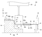
- FIG. 3 is a cross-sectional view showing the shaping apparatus 100 according to the present embodiment, showing a state before shaping the laminate 200.
- FIG. 4 is a cross-sectional view showing the shaping apparatus 100 according to the present embodiment, showing a state during shaping of the laminate 200.
- FIG. 5 is a cross-sectional view showing the shaping apparatus 100 according to the present embodiment, showing a state in which shaping of the laminate 200 is completed.
- the shaping apparatus 100 of the present embodiment includes a lower mold 10, an upper mold 20, a connecting sheet (connecting member) 30 connected to the laminate 200, and a tension generating mechanism 40. and an urging force generating mechanism 50 .
- the shaping device 100 shown in FIGS. 3 to 5 is arranged in a three-dimensional space.
- the X-axis, Y-axis, and Z-axis shown in FIGS. 3 to 5 are axes that intersect each other in a three-dimensional space.
- the X-axis is an axis extending along the installation surface S on which the lower mold 10 is installed
- the Z-axis is an axis extending in a direction orthogonal to the installation surface S on which the lower mold 10 is installed.
- the Y-axis is an axis orthogonal to both the X-axis and the Z-axis and extends along the depth direction of the paper surface of FIGS. 3 to 5 .
- the lower mold 10 is a block-shaped mold having a surface shape that shapes the laminate 200, and is made of, for example, a metal material.
- the lower die 10 has a top surface 11 , a side surface 12 , a convex surface (curved portion) 13 , a concave surface 14 (curved portion), and a bottom surface 15 as surface shapes for shaping the laminate 200 .
- 3 to 5 show cross sections of the lower die 10 at the central portion in the longitudinal direction LD along the axis Y.
- the upper surface 11 of the lower mold 10 is a flat surface extending along the X-axis.
- a side surface 12 of the lower die 10 is a surface extending flat along the Z-axis.
- a bottom surface 15 of the lower mold 10 is a surface extending flat along the X-axis.
- the convex surface 13 is a surface that connects the top surface 11 and the side surface 12, and as it approaches the side surface 12 from the top surface 11 along the X axis, the convex surface 13 changes from a surface along the X axis to a surface along the Z axis. It has an arc shape that gradually changes the line direction.
- the convex surface 13 is a portion including a convex shape along the second predetermined direction PD2 parallel to the X-axis.
- the concave surface 14 is a surface that connects the side surface 12 and the bottom surface 15, and as it approaches the bottom surface 15 from the side surface 12 along the Z-axis, the concave surface 14 changes from a surface along the Z-axis to a surface along the X-axis. It has an arc shape that gradually changes the line direction.
- the concave surface 14 is a portion including a concave shape along the second predetermined direction PD2 parallel to the X-axis.
- the laminate 200 has a first end region 200a and a second end region 200b along a first predetermined direction PD1 parallel to the axis X.
- the second end region 200b of the laminate 200 is fixed to the lower mold 10 while the first predetermined direction PD1 of the laminate 200 and the second predetermined direction PD2 of the lower mold 10 are aligned.
- the second end region 200 b of the laminate 200 is fixed at a predetermined position on the upper surface 11 of the lower mold 10 by the fixing member 16 .
- top surface 11 and bottom surface 15 may be surfaces that extend in a direction different from the X-axis, or may be non-flat surfaces.
- side surface 12 may be a surface extending in a direction different from the Z-axis, or may be a non-flat surface.
- the convex surface 13 may have any convex shape different from the arc shape.
- the concave surface 14 may have any concave shape different from the arc shape.
- the lower die 10 may have any shape including at least one of a concave shape and a convex shape along the first predetermined direction PD1.
- the upper mold 20 is a block-shaped mold that presses the laminate 200 with the second end region 200b fixed to the lower mold 10 against the lower mold 10 to shape the laminate 200 along the surface shape of the lower mold 10.
- the upper mold 20 presses the laminate 200 fixed to the lower mold 10 against the lower mold 10 to shape it along the surface shapes of the lower mold 10 and the upper mold 20 .
- the upper mold 20 has a lower surface 21 , a side surface 22 and a convex surface 23 as surface shapes for shaping the laminate 200 .
- the lower surface 21 of the upper mold 20 is a flat surface extending along the X-axis.
- a side surface 22 of the upper die 20 is a surface extending flat along the Z-axis.
- the convex surface 23 is a surface that connects the lower surface 21 and the side surface 22, and as it approaches the side surface 22 from the lower surface 21 along the X-axis, the convex surface 23 changes from a surface along the X-axis to a surface along the Z-axis. It has an arc shape that gradually changes the line direction.
- the convex surface 23 has a shape corresponding to the concave surface 14 of the lower mold 10 .
- the connection sheet 30 is a sheet that is connected to the suture material 300 that stitches the plurality of reinforcing fiber sheets of the laminate 200 together.
- the connecting sheet 30 is, for example, a nonwoven fabric or a film made of a resin material (for example, a thermoplastic resin material).
- the suturing material 300 is a member formed in a linear shape, and is formed of, for example, a resin material such as nylon, a metal material such as stainless steel, glass fiber, carbon fiber, or the like.
- the cutting step described later (the step of cutting the first end region 200a of the laminate 200) is omitted. good too.
- only a part of the first end region 200a may be cut in the cutting step. This is because, if the same material as that contained in the reinforcing fiber sheets constituting the laminate 200 is used, there are few quality problems even if the suturing material 300 is contained in the final product.
- the first end 30a contacts the upper surface of the first end region 200a of the laminate 200, and the second end 30b contacts the lower surface of the first end region 200a. It is placed in a state where A rod member 41 of a tension generating mechanism 40 is inserted into the connecting sheet 30 so as to come into contact with an intermediate portion 30c between the first end portion 30a and the second end portion 30b.
- the tension generating mechanism 40 applies tension in the direction of separating the first end region 200a of the laminated body 200 from the second end region 200b along the first predetermined direction PD1 through the connecting sheet 30, in a plurality of reinforcements of the laminated body 200. It is a mechanism for imparting to the fiber sheet.
- the tension generating mechanism 40 has a rod-shaped member 41 , a wire 42 , a support shaft 43 and a weight 44 .
- the rod-shaped member 41 is a rod-shaped member extending along the axis Y, and is connected to the wire 42 at both ends.
- the wire 42 has one end connected to the rod-like member 41 and the other end connected to the weight 44 .
- Wire 42 is supported by support shaft 43 .
- the tension due to the weight of the weight 44 directed downward along the axis Z is switched by the support shaft 43 to the tension along the axis X in the direction of moving the rod-shaped member 41 closer to the support shaft 43 .
- the support shaft 43 moves along the axis Z in conjunction with the position of the lower surface 21 of the upper die 20 .
- the position of the support shaft 43 in the direction of the axis line Z is switched so as to generate tension in the direction to bring the rod-like member 41 closer to the support shaft 43 along the axis line X.
- tension generating mechanism 40 shown in FIG. 3 applies tension to the laminate 200 by the weight of the weight 44, other embodiments may be used.
- tension may be applied to the laminate 200 via an elastically deformable member such as a spring.
- tension may be applied to the laminated body 200 by an actuator that operates hydraulically or the like.
- the biasing force generating mechanism 50 is a mechanism that generates a biasing force that biases the upper die 20 toward the lower die 10 .
- the biasing force generating mechanism 50 has a main body portion 51 whose position is fixed, and an expandable member 52 which can expand and contract in the direction along the axis Z with respect to the main body portion 51 and which is attached to the upper die 20 .
- the biasing force generating mechanism 50 generates a biasing force that presses the laminate 200 toward the lower die 10 by extending the elastic member 52 by hydraulic pressure, for example.
- FIG. 6 is a flow chart showing the shaping method according to this embodiment.
- step S101 a plurality of reinforcing fiber sheets are stacked one by one on an installation jig (not shown) having a flat installation surface to form a flat laminate 200 composed of a plurality of reinforcing fiber sheets.
- the first end region 200a of the laminate 200 is stitched together with the connecting sheet 30 with the linear suturing material 300.
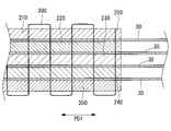
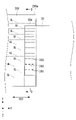
- FIG. 7 is a plan view of the portion A shown in FIG. 3 as viewed from above.
- FIG. 8 is a cross-sectional view of the laminate 200 shown in FIG. 7, taken along line BB.
- the laminate 200 is a state in which a plurality of reinforcing fiber sheets are laminated, and the first end regions 200a of the plurality of reinforcing fiber sheets in the first predetermined direction PD1 are linear suture materials. Sutured by 300.
- the first end region 200a of the laminate 200 and the connecting sheet 30 are sewn together in the direction along the axis Y with a sewing material 300.
- FIG. 7 indicates the suturing material 300 exposed from the top surface of the laminate 200, and the dashed line shown in FIG.
- the laminate 200 is obtained by laminating a reinforcing fiber sheet (sheet material) 210, a reinforcing fiber sheet 220, a reinforcing fiber sheet 230, a reinforcing fiber sheet 240, and a reinforcing fiber sheet 250. is.
- the first end 30 a of the connecting sheet 30 is arranged in contact with the upper surface of the reinforcing fiber sheet 210
- the second end 30 b of the connecting sheet 30 is arranged in contact with the lower surface of the reinforcing fiber sheet 210 .
- the laminate 200 shown in FIG. 8 is made by laminating five reinforcing fiber sheets, the laminate 200 in which any other number of reinforcing fiber sheets are laminated may be used.
- the first end region 200a of the laminate 200 and the connecting sheet 30 are sewn by seam stitches, but they may be sewn by regular reverse stitches or half reverse stitches. Also, in FIG. 7 , the stitches are sewn along the axis Y at two different positions in the direction of the axis X, but they may be sewn at one place or at three or more places.
- the second end region 200b of the laminate 200 is placed on the upper surface 11 of the lower mold 10 with the first predetermined direction PD1 of the laminate 200 aligned with the second predetermined direction PD2 of the lower mold 10. fixed.
- the laminate 200 is fixed to the lower mold 10 by attaching the fixing member 16 to the upper surface 11 and sandwiching the second end region 200 b between the fixing member 16 and the upper surface 11 .
- the biasing force generating mechanism 50 presses the upper mold 20 downward along the axis Z against the laminate 200 to shape the laminate 200 along the surface shape of the lower mold 10.
- the upper mold 20 arranged above the upper surface of the laminate 200 is moved downward, the lower surface 21 of the upper mold 20 comes into contact with the upper surface of the laminate 200, resulting in the state shown in FIG.
- the plurality of reinforcing fiber sheets of the laminate 200 are arranged in the first predetermined direction PD1 from the second end region 200b to the first end region 200a by the connecting sheet 30 that is connected to the suture material 300 .
- Tension is applied in the direction of pulling apart. Therefore, when the upper mold 20 comes into contact with the upper surface of the laminate 200 and moves downward, the laminate 200 is prevented from wrinkling.
- the plurality of reinforcing fiber sheets of the laminate 200 include a connecting sheet to be connected to the suture material 300. 30, tension is applied in a direction to separate the first end region 200a from the second end region 200b along the first predetermined direction PD1. Therefore, when the upper mold 20 contacts the upper surface of the laminate 200 and moves downward, the laminate 200 is prevented from wrinkling.
- the upper mold 20 is moved upward. Also, the suture material 300 is removed from the first end region 200a of the laminate 200, and the connecting sheet 30 is removed from the first end region 200a. Note that a portion of suture material 300 may remain unremoved from first end region 200a of laminate 200 .
- step S105 the laminate 200 shaped along the surface shapes of the lower mold 10 and the upper mold 20 is placed in a mold (not shown). Thereafter, a resin material is injected into the mold to impregnate the plurality of reinforcing fiber sheets of the laminate 200 with the resin material.
- the resin material impregnated in the plurality of reinforcing fiber sheets of the laminate 200 is cured.
- the resin material is thermosetting, the resin material is heated to a curing temperature or higher to cure the resin material.
- the resin material is a thermoplastic resin, the resin material is hardened by cooling to below the softening temperature.
- step S107 the first end region 200a of the laminated body 200 in which the resin material has hardened is cut using a cutting mechanism (not shown). By cutting the first end region 200a of the laminate 200 with the cutting mechanism, it is possible to remove the portion that is not required in the final product.
- steps S101 to S107 described above the composite material forming method for forming the composite material by forming the laminate 200 using the forming apparatus 100 is executed.
- the laminated body 200 shown in FIGS. 7 and 8 has the first end region 200a stitched in the direction along the axis Y with the suturing material 300, it may be in another mode.
- the first end region 200a of the laminate 200 may be sewn in the direction along the axis X with a suture material 300.
- FIG. 9 shows that the first end region 200a of the laminate 200 may be sewn in the direction along the axis X with a suture material 300.
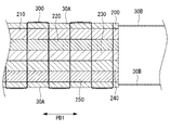
- FIG. 9 is a plan view showing a first modification of the laminate 200 of the present disclosure. As shown in FIG. 9, the first end region 200a of the laminate 200 and the connecting sheet 30 are sewn together in the direction along the axis X with a sewing material 300. As shown in FIG. 9 indicates the suture material 300 exposed from the top surface of the laminate 200, and the dashed line shown in FIG.
- FIG. 10 is a cross-sectional view of the laminate 200 shown in FIG. 9 taken along line CC, showing a state in which the laminate 200 has no interlayer slippage.
- FIG. 11 is a cross-sectional view of the laminate 200 shown in FIG. 9 taken along line CC, and shows a state in which interlayer slip occurs in the laminate 200.
- the laminate 200 is obtained by laminating a reinforcing fiber sheet 210, a reinforcing fiber sheet 220, a reinforcing fiber sheet 230, a reinforcing fiber sheet 240, and a reinforcing fiber sheet 250.
- the first end 30 a of the connecting sheet 30 is arranged in contact with the upper surface of the reinforcing fiber sheet 210
- the second end 30 b of the connecting sheet 30 is arranged in contact with the lower surface of the reinforcing fiber sheet 250 .
- the reinforcing fiber sheets 210 , 220 , 230 , 240 , 250 are sewn together with the first end 30 a and the second end 30 b of the connecting sheet 30 with a suture material 300 .
- the reinforcing fiber sheets forming each layer of the laminate 200 along the axis X can cause interlaminar slippage.
- interlayer slippage it is possible to shape the laminate 200 along the surface shapes of the lower mold 10 and the upper mold 20 and to suppress the occurrence of wrinkles in the laminate 200 .
- the first end 30a of the connecting sheet 30 is arranged on the upper surface of the laminated body 200, and the second end 30b of the connecting sheet 30 is arranged on the lower surface of the laminated body 200.
- a connecting sheet 30 may be sandwiched between a pair of reinforcing fiber sheets arranged adjacent to each other.
- FIG. 12 is a cross-sectional view showing a second modification of the laminate 200 of the present disclosure.
- the connecting sheet 30 is sandwiched between the reinforcing fiber sheets 210 and 220, and the connecting sheet 30 is connected between the reinforcing fiber sheets 220 and 230. It sandwiches the sheet 30 .
- the connecting sheet 30 is sandwiched between the reinforcing fiber sheet 230 and the reinforcing fiber sheet 240, and the connecting sheet 30 is sandwiched between the reinforcing fiber sheet 240 and the reinforcing fiber sheet 250.
- the reinforcing fiber sheets 210, 220, 230, 240, and 250 are stitched together with a plurality of connecting sheets 30 sandwiched therebetween by a stitching material 300.
- a plurality of reinforcing fiber sheets are stacked with the connecting sheet 30 sandwiched between a pair of reinforcing fiber sheets arranged adjacent to each other.
- the plurality of connecting sheets 30 are stitched together with the reinforcing fiber sheets 210, 220, 230, 240, 250 with the stitching material 300. As shown in FIG.
- the first end 30a of the connecting sheet 30 is arranged on the upper surface of the laminated body 200, and the second end 30b of the connecting sheet 30 is arranged on the lower surface of the laminated body 200.
- a plate-shaped connecting member 30A may be arranged instead of the connecting sheet 30, instead of the connecting sheet 30, a plate-shaped connecting member 30A may be arranged.
- FIG. 13 is a cross-sectional view showing a third modification of the laminate 200 of the present disclosure.
- the connecting member 30A is arranged in contact with the upper surface of the reinforcing fiber sheet 210 and the connecting member 30A is arranged in contact with the lower surface of the reinforcing fiber sheet 250 .
- the reinforcing fiber sheets 210, 220, 230, 240, 250 are sewn together with the pair of connecting members 30A by the sewing material 300. As shown in FIG.
- the connecting member 30A is formed in a plate shape, the tension of the suture material 300 is not applied locally to the reinforcing fiber sheet 210 and the reinforcing fiber sheet 250.
- the tension of suture material 300 is transmitted to reinforcing fiber sheet 210 and reinforcing fiber sheet 250 via connecting member 30A. Therefore, it is possible to appropriately prevent the reinforcement fiber sheet 210 and the reinforcement fiber sheet 250 from being deformed due to local tension.
- a wire 30B is connected to the connecting member 30A, and a tension along the first predetermined direction PD1 is applied via the wire 30B.
- the plurality of reinforcing fiber sheets of the laminate 200 are tensioned in the direction of separating the first end region 200a from the second end region 200b along the first predetermined direction PD1 by the connecting member 30A connected to the suture material 300. is given. Therefore, when the upper mold 20 comes into contact with the upper surface of the laminate 200 and moves downward, the laminate 200 is prevented from wrinkling.
- the laminated body 200 of the third modified example applies tension to the connecting member 30A formed in a plate shape via the wire 30B
- other aspects may be adopted.
- a wire (connecting member) 30C may be connected to the suture material 300 to apply tension directly to the suture material 300.
- FIG. 14 is a cross-sectional view showing a fourth modification of the laminate 200 of the present disclosure.
- the connecting member 30A is arranged in contact with the upper surface of the reinforcing fiber sheet 210 and the connecting member 30A is arranged in contact with the lower surface of the reinforcing fiber sheet 250 .
- the reinforcing fiber sheets 210, 220, 230, 240, 250 are sewn together with the pair of connecting members 30A by the sewing material 300. As shown in FIG.
- the wire 30C formed in a linear shape is connected to the suture material 300 respectively.
- a tension along the first predetermined direction PD1 is applied to the suture material 300 via the wire 30C.
- the suture material 300 applies tension to the reinforcing fiber sheets of the laminate 200 in a direction to separate the first end region 200a from the second end region 200b along the first predetermined direction PD1. Therefore, when the upper mold 20 comes into contact with the upper surface of the laminate 200 and moves downward, the laminate 200 is prevented from wrinkling.
- the entire first end 30a of the connecting sheet 30 is in contact with the reinforcing fiber sheet 210, and the entire second end 30b of the connecting sheet 30 is in contact with the reinforcing fiber sheet 250.
- other embodiments may also be possible. For example, as shown in FIG. 16, only a portion of the first end portion 30Da of the connecting sheet 30D is brought into contact with the reinforcing fiber sheet 210, and only a portion of the second end portion 30Db of the connecting sheet 30D is brought into contact with the reinforcing fiber sheet 250. You may make it contact.
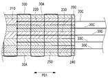
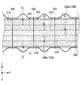
- FIG. 15 is a plan view showing a fifth modification of the laminate 200 of the present disclosure.
- FIG. 16 is a cross-sectional view of the laminate 200 shown in FIG. 15, taken along line DD.
- a slit SL indicated by a dashed line in FIG. 15 indicates the position of a cut extending along the first predetermined direction PD1 formed in the reinforcing fiber sheets forming the laminate 200. As shown in FIG.
- 11 slits SL are shown in FIG. 15, the 11 slits SL are not formed in one reinforcing fiber sheet, and any of the 11 slits (for example, 3) are formed. It is assumed that a slit SL is formed at . Also, the number of locations where the slits SL are formed may be any number other than eleven.
- the reason why the slit SL is formed in the reinforcing fiber sheet of this modification is that when the laminate 200 is shaped by the lower mold 10 and the upper mold 20 having portions curved in the direction along the axis Y, the laminate This is to prevent the 200 from wrinkling.
- the first end portion 30Da of the connection sheet 30D of this modified example contacts the reinforcing fiber sheet 210 at a position sewn by the suture material 300 in the direction along the axis Y, and contacts the reinforcing fiber sheet 210 at other positions. are arranged in a corrugated shape so as not to come into contact with the reinforcing fiber sheet 210 .
- the second end portion 30Db of the connection sheet 30D of this modification contacts the reinforcing fiber sheet 250 at the position sewn by the sewing material 300 in the direction along the axis Y, and the reinforcing fiber sheet at other positions. It is arranged in a corrugated shape so as not to contact 250 .
- the reason why only a part of the first end portion 30Da of the connecting sheet 30D is in contact with the reinforcing fiber sheet 210 is that when the width of the slit SL of the reinforcing fiber sheet expands along the axis Y, it follows the expansion. This is for deforming the connecting sheet 30D.
- the connecting sheet 30D By arranging the connecting sheet 30D in a wavy shape along the axis Y, the connecting sheet 30D does not prevent the width of the slit SL from expanding along the axis Y when the reinforcing fiber sheet is deformed.
- the connecting sheet 30D When arranging the connecting sheet 30D in a corrugated shape along the axis Y, for example, it is desirable to use a pipe P indicated by a dashed line in FIG.
- the pipe P is a cylindrical member arranged along the axis X so as to come into contact with the reinforcing fiber sheet.
- the connecting sheet 30D is arranged along the shape of the pipe P in a corrugated shape. After the connecting sheet 30 ⁇ /b>D is stitched to the laminate 200 , the pipe P is pulled out from the connecting sheet 30 .
- connection sheet 30D may be made of a flexible material that can be deformed along the axis Y, and the entire connection sheet 30D may be brought into contact with the reinforcing fiber sheet 210.
- slits SL extending along the first predetermined direction PD1 are formed in the reinforcing fiber sheet, and the laminated body 200 is sewn with the suture material 300 along the first predetermined direction PD1.
- the suture material 300 is used to suture the laminate 200 along the first predetermined direction PD1 so that the suture material 300 does not interfere with the expansion of the slit SL along the axis Y.
- the laminated body 200 is stitched along the axis Y with the suturing material 300, the slit SL is prevented from expanding along the axis Y.
- the laminate 200 of the fifth modified example is sutured with the suture material 300 along the first predetermined direction PD1.
- the laminated body 200 may be sewn with the suture material 300 in the direction of alternate folding along the Y axis.
- FIG. 17 is a plan view showing a sixth modification of the laminate 200 of the present disclosure.
- the laminated body 200 of this modified example has the suture material 300 so that the suture material 300 does not obstruct the spread of the slit SL along the axis Y, so that the suture material 300 moves along the axis Y. Together, they are stitched so as to alternately fold back in the direction along the axis X.
- a shaping method according to the present disclosure is a shaping method for shaping a laminate (200) in which a plurality of sheet materials containing reinforcing fibers are laminated, and in a state in which a plurality of the sheet materials are laminated, a plurality of the A sewing step (S102) of sewing the first end region (200a) of the sheet material in the first predetermined direction (PD1) with a linear sewing material (300), and forming a concave shape along the second predetermined direction (PD2).
- a first shaping die (10) having a curved portion (13) including at least one of a convex shape and the first predetermined direction of the laminate being aligned with the second predetermined direction; 1 A fixing step (S103) of fixing a second end region (200b) in a predetermined direction; and a shaping step (S104) of shaping the laminate along the surface shape of the first shaping mold, wherein the shaping step includes changing the first end region to the second end region
- the laminate is shaped in a state in which tension is applied to the plurality of sheet materials by a connecting member (30) connected to the suture material in a direction of separating from the sheet material along the first predetermined direction.
- the second end region of the laminate in which the first end region in the first predetermined direction is sewn with a linear suturing material has a concave shape along the second predetermined direction.
- it is fixed to a first shaping mold having a curved portion including at least one of a convex shape, with the first predetermined direction and the second predetermined direction aligned.
- the laminate is shaped along the surface shape of the first shaping die by pressing the second shaping die.
- the first end regions of the plurality of sheet materials in the first predetermined direction are sewn with a linear suture material, and the suture material is connected with the connecting member.
- the connecting member imparts tension to the plurality of sheet materials in a direction separating the first end regions from the second end regions when being shaped by the first shaping die and the second shaping die. Therefore, when shaping a laminate in which a plurality of sheet materials containing reinforcing fibers are laminated, a desired tension is maintained in the plurality of sheet materials to shape the laminate so that wrinkles do not occur. be able to.
- the shaping method according to the present disclosure preferably includes a cutting step (S107) of cutting the first end region of the laminate. According to the shaping method according to this configuration, since the first end region of the laminate is cut, the portion that is unnecessary in the final product can be appropriately removed.
- the connecting member is a member formed in a sheet shape or a plate shape
- the sewing step includes connecting the connecting member arranged on the front surface and the back surface of the laminate to a plurality of the sheets.
- a configuration that sutures with the material is preferred.
- the connecting members formed in a sheet or plate shape and arranged on the front and back surfaces of the laminate are stitched together with the plurality of sheet materials. Therefore, by applying tension to the sheet-like or plate-like connecting member, a desired tension can be applied to a plurality of sheet materials sewn together by the suture material connected to the connecting member.
- the connecting member is a linearly formed member. According to the shaping method according to this configuration, since the linearly formed connecting member is connected to the suturing material, the linearly formed connecting member can be connected to the connecting member by applying tension to the connecting member. A desired tension can be applied to a plurality of sheets of material sewn together by a suture material.
- the suturing step sews the connecting member together with a plurality of the sheet materials.
- a connecting member formed in a sheet shape is sandwiched between a pair of adjacently arranged sheet materials, and the connecting member is sewn together with the plurality of sheet materials. Since tension is applied to the sheet-like connecting member sandwiched between the pair of sheet materials, appropriate tension can be applied to each of the pair of sheet materials sandwiching the connecting member.
- a shaping device is a shaping device that shapes a laminate obtained by laminating a plurality of sheet materials containing reinforcing fibers, wherein the laminate is a state in which a plurality of sheet materials are laminated, and a plurality of The first end region of the sheet material in the first predetermined direction is sewn with a linear suture material, and has a curved portion including at least one of a concave shape and a convex shape along the second predetermined direction a first shaping die to which a second end region of the laminate in the first predetermined direction is fixed with the first predetermined direction aligned with the second predetermined direction; a second shaping die that presses the laminate fixed to the die against the first shaping die to shape it along the surface shape of the first shaping die; and a connecting member that is connected to the suture material. and a tension generating mechanism that applies tension to the plurality of sheet materials via the connecting member in a direction
- the second end region of the laminate in which the first end region in the first predetermined direction is stitched with a linear suturing material, has a concave shape along the second predetermined direction.
- it is fixed to a first shaping mold having a curved portion including at least one of a convex shape, with the first predetermined direction and the second predetermined direction aligned.
- the laminate is shaped along the surface shape of the first shaping die by pressing the second shaping die.
- the first end regions of the plurality of sheet materials in the first predetermined direction are sewn with a linear suturing material, and the connecting member is connected to the suturing material.
- the connecting member imparts tension to the plurality of sheet materials in a direction separating the first end regions from the second end regions when being shaped by the first shaping die and the second shaping die. Therefore, when shaping a laminate in which a plurality of sheet materials containing reinforcing fibers are laminated, a desired tension is maintained in the plurality of sheet materials to shape the laminate so that wrinkles do not occur. be able to.
- the shaping device preferably has a configuration including a cutting mechanism that cuts the first end region of the laminate. According to the forming apparatus according to this configuration, the first end region of the laminate is cut, so it is possible to appropriately remove the portion that is unnecessary in the final product.
- the connecting member is formed in a sheet or plate shape, is arranged on the front surface and the back surface of the laminate, and is sewn together with the plurality of sheet materials by the suture material. is preferred.
- the connecting members formed in the shape of sheets or plates and arranged on the front and back surfaces of the laminate are sewn together with the plurality of sheet materials. Therefore, by applying tension to the sheet-like or plate-like connecting member, a desired tension can be applied to a plurality of sheet materials sewn together by the suture material connected to the connecting member.
- connection member is formed linearly and connected to the suture material.
- the linearly formed connecting member since the linearly formed connecting member is connected to the suturing material, the linearly formed connecting member can be connected to the connecting member by applying tension to the connecting member. A desired tension can be applied to a plurality of sheets of material sewn together by a suture material.
- the connecting member is sandwiched between a pair of the sheet materials that are formed in a sheet shape and are arranged adjacent to each other, and is joined together with the plurality of sheet materials by the suture material. Sutured configurations are preferred.
- the connecting member formed in a sheet shape is sandwiched between a pair of adjacently arranged sheet materials, and the connecting member is sewn together with the plurality of sheet materials. Since tension is applied to the sheet-like connecting member sandwiched between the pair of sheet materials, appropriate tension can be applied to each of the pair of sheet materials sandwiching the connecting member.
Landscapes
- Engineering & Computer Science (AREA)
- Chemical & Material Sciences (AREA)
- Composite Materials (AREA)
- Mechanical Engineering (AREA)
- Textile Engineering (AREA)
- Moulding By Coating Moulds (AREA)
- Laminated Bodies (AREA)
Priority Applications (3)
| Application Number | Priority Date | Filing Date | Title |
|---|---|---|---|
| PCT/JP2021/009781 WO2022190312A1 (ja) | 2021-03-11 | 2021-03-11 | 賦形方法および賦形装置 |
| US18/018,977 US12330382B2 (en) | 2021-03-11 | 2021-03-11 | Shaping method and shaping device |
| JP2023505008A JP7351038B2 (ja) | 2021-03-11 | 2021-03-11 | 賦形方法および賦形装置 |
Applications Claiming Priority (1)
| Application Number | Priority Date | Filing Date | Title |
|---|---|---|---|
| PCT/JP2021/009781 WO2022190312A1 (ja) | 2021-03-11 | 2021-03-11 | 賦形方法および賦形装置 |
Publications (1)
| Publication Number | Publication Date |
|---|---|
| WO2022190312A1 true WO2022190312A1 (ja) | 2022-09-15 |
Family
ID=83226503
Family Applications (1)
| Application Number | Title | Priority Date | Filing Date |
|---|---|---|---|
| PCT/JP2021/009781 Ceased WO2022190312A1 (ja) | 2021-03-11 | 2021-03-11 | 賦形方法および賦形装置 |
Country Status (3)
| Country | Link |
|---|---|
| US (1) | US12330382B2 (https=) |
| JP (1) | JP7351038B2 (https=) |
| WO (1) | WO2022190312A1 (https=) |
Cited By (1)
| Publication number | Priority date | Publication date | Assignee | Title |
|---|---|---|---|---|
| WO2024232109A1 (ja) * | 2023-05-11 | 2024-11-14 | 三菱重工業株式会社 | 賦形装置および賦形方法 |
Citations (4)
| Publication number | Priority date | Publication date | Assignee | Title |
|---|---|---|---|---|
| JP2014152760A (ja) * | 2013-02-13 | 2014-08-25 | Ihi Corp | ファンブレードの製造方法および製造装置 |
| US20150314536A1 (en) * | 2012-12-21 | 2015-11-05 | Vestas Wind Systems A/S | Method of manufacturing a wind turbine blade using pre-fabricated stacks of reinforcing material |
| JP2016124125A (ja) * | 2014-12-26 | 2016-07-11 | 東レ株式会社 | 繊維強化プラスチックの製造方法 |
| JP2017193164A (ja) * | 2016-03-04 | 2017-10-26 | ザ・ボーイング・カンパニーThe Boeing Company | 複合部品の動的成形ツール |
Family Cites Families (4)
| Publication number | Priority date | Publication date | Assignee | Title |
|---|---|---|---|---|
| US6814916B2 (en) | 2002-08-30 | 2004-11-09 | The Boeing Company | Forming method for composites |
| JP5556147B2 (ja) * | 2009-11-30 | 2014-07-23 | 三菱レイヨン株式会社 | プリフォームの製造装置及び製造方法 |
| US10479029B2 (en) | 2015-01-16 | 2019-11-19 | The Boeing Company | Composite forming apparatus |
| US10875232B2 (en) | 2017-04-04 | 2020-12-29 | The Boeing Company | Composite part and method for making composite part |
-
2021
- 2021-03-11 JP JP2023505008A patent/JP7351038B2/ja active Active
- 2021-03-11 WO PCT/JP2021/009781 patent/WO2022190312A1/ja not_active Ceased
- 2021-03-11 US US18/018,977 patent/US12330382B2/en active Active
Patent Citations (4)
| Publication number | Priority date | Publication date | Assignee | Title |
|---|---|---|---|---|
| US20150314536A1 (en) * | 2012-12-21 | 2015-11-05 | Vestas Wind Systems A/S | Method of manufacturing a wind turbine blade using pre-fabricated stacks of reinforcing material |
| JP2014152760A (ja) * | 2013-02-13 | 2014-08-25 | Ihi Corp | ファンブレードの製造方法および製造装置 |
| JP2016124125A (ja) * | 2014-12-26 | 2016-07-11 | 東レ株式会社 | 繊維強化プラスチックの製造方法 |
| JP2017193164A (ja) * | 2016-03-04 | 2017-10-26 | ザ・ボーイング・カンパニーThe Boeing Company | 複合部品の動的成形ツール |
Cited By (1)
| Publication number | Priority date | Publication date | Assignee | Title |
|---|---|---|---|---|
| WO2024232109A1 (ja) * | 2023-05-11 | 2024-11-14 | 三菱重工業株式会社 | 賦形装置および賦形方法 |
Also Published As
| Publication number | Publication date |
|---|---|
| JP7351038B2 (ja) | 2023-09-26 |
| JPWO2022190312A1 (https=) | 2022-09-15 |
| US12330382B2 (en) | 2025-06-17 |
| US20240034010A1 (en) | 2024-02-01 |
Similar Documents
| Publication | Publication Date | Title |
|---|---|---|
| US8940119B2 (en) | Process and apparatus for producing beam member | |
| JP6262842B2 (ja) | 成形中の複合積層体における層のしわを低減するための方法及び装置 | |
| US20080217806A1 (en) | Continuous molding method of composite material having stepwise sectional thickness | |
| WO2009088029A1 (ja) | 湾曲形状強化繊維基材、およびそれを用いた積層体、プリフォーム、繊維強化樹脂複合材料とそれらの製造方法 | |
| WO2008062818A1 (en) | Reinforced thermoplastic-resin multilayer sheet material, process for producing the same, and method of forming molded thermoplastic-resin composite material | |
| JP2009502585A (ja) | 複合構造部材を製造する装置ならびに方法 | |
| JP6411677B1 (ja) | 複合材部品の製造方法、および、複合材部品製造装置 | |
| CN111201132B (zh) | 制造面状复合构件的方法和由此制造的复合构件 | |
| MXPA04011574A (es) | Unidad laminar mixta rizada. | |
| WO2012026031A1 (ja) | 繊維強化樹脂材の製造方法 | |
| US20220072816A1 (en) | Articulated Forming Caul for Composite Blank Vacuum Forming | |
| US8303757B2 (en) | Tensioning device for composite structures | |
| JP7351038B2 (ja) | 賦形方法および賦形装置 | |
| JP7225320B2 (ja) | 賦形方法および賦形装置 | |
| JP4873879B2 (ja) | 多軸多層補強シートの製造方法及び製造装置 | |
| JP2006188597A (ja) | 繊維強化プラスチックの製造方法 | |
| JP4576942B2 (ja) | プリフォームの製造方法およびプリフォームの製造装置 | |
| CN110191788B (zh) | 纤维增强塑料的制造方法 | |
| JP6411673B1 (ja) | 複合材部品の製造方法、および、複合材部品製造装置 | |
| JP2006056022A (ja) | 湾曲したfrp桁材用の強化繊維プリフォームの製作方法 | |
| JP2010253714A (ja) | 繊維強化プラスチックの成形方法 | |
| JP7275394B2 (ja) | 賦形方法および賦形装置 | |
| JP5614384B2 (ja) | 強化繊維シート、繊維強化複合材、及び強化繊維シートの製造方法、並びに繊維強化複合材の製造方法 | |
| JP7300698B2 (ja) | プリプレグの製造方法及び製造装置 | |
| US12090743B2 (en) | Sheet-shaped reinforcing fiber substrate and manufacturing method therefor |
Legal Events
| Date | Code | Title | Description |
|---|---|---|---|
| 121 | Ep: the epo has been informed by wipo that ep was designated in this application |
Ref document number: 21930165 Country of ref document: EP Kind code of ref document: A1 |
|
| ENP | Entry into the national phase |
Ref document number: 2023505008 Country of ref document: JP Kind code of ref document: A |
|
| WWE | Wipo information: entry into national phase |
Ref document number: 18018977 Country of ref document: US |
|
| NENP | Non-entry into the national phase |
Ref country code: DE |
|
| 122 | Ep: pct application non-entry in european phase |
Ref document number: 21930165 Country of ref document: EP Kind code of ref document: A1 |
|
| WWG | Wipo information: grant in national office |
Ref document number: 18018977 Country of ref document: US |