WO2022186263A1 - 画像処理装置、画像処理方法及びプログラムが格納された非一時的なコンピュータ可読媒体 - Google Patents
画像処理装置、画像処理方法及びプログラムが格納された非一時的なコンピュータ可読媒体 Download PDFInfo
- Publication number
- WO2022186263A1 WO2022186263A1 PCT/JP2022/008813 JP2022008813W WO2022186263A1 WO 2022186263 A1 WO2022186263 A1 WO 2022186263A1 JP 2022008813 W JP2022008813 W JP 2022008813W WO 2022186263 A1 WO2022186263 A1 WO 2022186263A1
- Authority
- WO
- WIPO (PCT)
- Prior art keywords
- image
- data
- space
- estimation processing
- processing unit
- Prior art date
- Legal status (The legal status is an assumption and is not a legal conclusion. Google has not performed a legal analysis and makes no representation as to the accuracy of the status listed.)
- Ceased
Links
Images










Classifications
-
- G—PHYSICS
- G06—COMPUTING OR CALCULATING; COUNTING
- G06T—IMAGE DATA PROCESSING OR GENERATION, IN GENERAL
- G06T12/00—Tomographic reconstruction from projections
- G06T12/20—Inverse problem, i.e. transformations from projection space into object space
-
- A—HUMAN NECESSITIES
- A61—MEDICAL OR VETERINARY SCIENCE; HYGIENE
- A61B—DIAGNOSIS; SURGERY; IDENTIFICATION
- A61B5/00—Measuring for diagnostic purposes; Identification of persons
- A61B5/05—Detecting, measuring or recording for diagnosis by means of electric currents or magnetic fields; Measuring using microwaves or radio waves
- A61B5/055—Detecting, measuring or recording for diagnosis by means of electric currents or magnetic fields; Measuring using microwaves or radio waves involving electronic [EMR] or nuclear [NMR] magnetic resonance, e.g. magnetic resonance imaging
-
- G—PHYSICS
- G01—MEASURING; TESTING
- G01N—INVESTIGATING OR ANALYSING MATERIALS BY DETERMINING THEIR CHEMICAL OR PHYSICAL PROPERTIES
- G01N24/00—Investigating or analyzing materials by the use of nuclear magnetic resonance, electron paramagnetic resonance or other spin effects
-
- G—PHYSICS
- G01—MEASURING; TESTING
- G01R—MEASURING ELECTRIC VARIABLES; MEASURING MAGNETIC VARIABLES
- G01R33/00—Arrangements or instruments for measuring magnetic variables
- G01R33/20—Arrangements or instruments for measuring magnetic variables involving magnetic resonance
- G01R33/44—Arrangements or instruments for measuring magnetic variables involving magnetic resonance using nuclear magnetic resonance [NMR]
- G01R33/48—NMR imaging systems
-
- G—PHYSICS
- G06—COMPUTING OR CALCULATING; COUNTING
- G06T—IMAGE DATA PROCESSING OR GENERATION, IN GENERAL
- G06T2210/00—Indexing scheme for image generation or computer graphics
- G06T2210/41—Medical
-
- G—PHYSICS
- G06—COMPUTING OR CALCULATING; COUNTING
- G06T—IMAGE DATA PROCESSING OR GENERATION, IN GENERAL
- G06T2211/00—Image generation
- G06T2211/40—Computed tomography
- G06T2211/441—AI-based methods, deep learning or artificial neural networks
Definitions
- the present disclosure relates to an image processing device, an image processing method, and a non-transitory computer-readable medium storing a program.
- a nuclear magnetic resonance imaging (MRI) apparatus applies a magnetic field to the tissue of a living body, for example, a human body, and utilizes the nuclear magnetic resonance (NMR) phenomenon that occurs at that time. It is a device that acquires two-dimensional or three-dimensional image information.
- An MRI apparatus has excellent features such as being able to image tissues that cannot be imaged by a CT (Computed Tomography) apparatus and not being exposed to radiation.
- MRI when reading NMR signals during imaging, a gradient magnetic field is applied to the subject to encode the position, and imaging data is acquired as a collection of raw data in the k-space, which is the measurement space. Since the k-space and the real space are in a Fourier transform relationship with each other, an image in the real space is reconstructed by Fourier transforming the imaging data in the k-space (Patent Documents 1 to 3).
- Imaging a subject with an MRI device takes a relatively long time, generally several tens of minutes. Therefore, in order to reduce the burden on the subject due to the long time required for imaging and to improve the throughput of imaging with an MRI apparatus, sampling is performed by thinning out the measurement points in the k-space, and the unmeasured data between the measurement points is interpolated.
- a high-speed imaging technique is used that compensates for the resolution of the image by As a high-speed imaging method, for example, there is a compressed sensing method.
- Other known high-speed imaging techniques include, for example, the FSE (Fast Spin Echo) method, the EPI (Echo Planner Imaging) method, and the GE (Gradient Echo) method.
- thinning out the measurement points causes problems such as a decrease in the resolution of the reconstructed image, an increase in artifacts, an increase in noise, etc., resulting in a decrease in image quality.
- FIG. 28 shows an example of k-space raw data and reconstructed images when normal high-definition imaging and high-speed imaging are performed by the MRI apparatus.
- the vertical axis represents phase encoding and the horizontal axis represents frequency encoding.
- the entire range of phase encoding to be measured is measured, so the reconstructed image is a fine image.
- imaging takes a relatively long time.
- the imaging at the position indicated by s is skipped, and the blackened portions in the k-space raw data correspond to the thinned measurement points.
- the number of measurement points is reduced to about 1/2 compared to high-definition imaging.
- the image reconstructed from this image is inferior to the high-definition image due to the lack of information due to thinning, and artifacts are generated. be done. Therefore, if the image quality does not meet the required standard, measures such as increasing the number of measurement points are required, and the reduction in imaging time due to high-speed imaging is further restricted.
- An image processing apparatus acquires low-density sampling k-space raw data obtained by imaging a subject by thinning out measurement points with an MRI apparatus, and obtains low-density sampling k-space raw data. and a data acquisition unit that outputs input data based on the above, performs estimation processing by inputting the input data to a trained model, and outputs restored image data in which the image quality that has been reduced due to the thinned measurement points is recovered. It has an estimation processing section and an image display section for displaying the restored image data. As a result, it is possible to recover the image quality of the input data that has been deteriorated due to the thinned-out measurement points, and display a high-quality image based on the recovered image data whose image quality has been recovered.
- An image processing apparatus is the image processing apparatus described above, wherein the data acquisition unit includes an interpolated k-space raw data obtained by interpolating the thinned measurement points of the low-density sampling k-space raw data. data, outputs the interpolated k-space raw data as the input data to the estimation processing unit, and the estimation processing unit inputs the interpolated k-space raw data to the trained model for estimation processing and outputting estimated k-space raw data whose image quality has been restored by the thinned-out measurement points, and outputting the restored image data reconstructed by Fourier transforming the estimated k-space raw data. It is desirable to be configured as a k-space estimation processing unit. Thereby, input data, which is k-section raw data, can be appropriately input to the estimation processing unit.
- An image processing apparatus is the image processing apparatus described above, wherein the data acquisition unit performs an inverse Fourier transform on image data reconstructed by Fourier transforming the low-density sampling k-space raw data. It is desirable to obtain the interpolated k-space raw data by performing inverse reconstruction using . This allows the low density sampling k-space raw data to be suitably interpolated.
- An image processing device is the image processing device described above, wherein the data acquisition unit uses image data obtained by Fourier transforming the low-density sampling k-space raw data as the input data, and the estimation processing unit and the estimation processing unit performs estimation processing by inputting the converted image data to the learned model, and restores the restored image in which the image quality deteriorated due to the thinned-out measurement points is restored. It is desirable to configure it as an image space estimation processing unit that outputs data. Accordingly, input data, which is image data, can be appropriately input to the estimation processing unit.
- An image processing device is the image processing device described above, wherein the estimation processing unit includes one or more k-space estimation processing units and one or more image space estimation processing units connected in series.
- the k-space estimation processing unit performs estimation processing by inputting k-space raw data, which is input data, into the trained model, outputs k-space raw data whose image quality has been restored, and Second image data reconstructed by Fourier transforming the k-space raw data is output, and the image space estimation processing unit performs estimation processing by inputting the image data as input data to the trained model.
- the k-space estimation processing unit when image data whose image quality has been restored is output, and the k-space estimation processing unit is arranged after the image space estimation processing unit, the image space estimation processing unit and the k-space estimation processing unit and an image inverse reconstruction unit for outputting k-space raw data obtained by inversely reconstructing the image data output from the preceding image space estimation processing unit by inverse Fourier transform to the subsequent k-space estimation processing unit. and the image data output from the end of the serial arrangement of the k-space estimation processing unit and the image space estimation processing unit is preferably output as the restored image data.
- multistage estimation processing can be performed, and the image quality of the restored image data can be further improved.
- An image processing apparatus is the above image processing apparatus, wherein the k-space estimation processing unit and the image space estimation processing unit are arranged serially at the head of the k-space estimation processing unit.
- the data acquisition unit converts the thinned-out measurement points of the low-density sampling k-space raw data into interpolated k-space raw data, and uses the interpolated k-space raw data as the input data.
- the data acquisition unit Preferably, image data obtained by Fourier transforming the low-density sampling k-space raw data is output as the input data to the image space estimation processing section at the head.
- image data obtained by Fourier transforming the low-density sampling k-space raw data is output as the input data to the image space estimation processing section at the head.
- An image processing apparatus is the above-described image processing apparatus, wherein the data acquisition unit is configured to obtain a background image obtained in advance by thinning out measurement points in the MRI apparatus and capturing an image of the subject.
- reading learning data which is density-sampling k-space raw data
- teacher data which is high-density sampling k-space raw data obtained in advance by imaging the subject without thinning out measurement points with the MRI apparatus;
- Input data for learning based on the read learning data and the teacher data is output to the estimation processing unit, and the estimation processing unit performs supervised learning based on the input data for learning, thereby obtaining the learned model.
- the estimation processing unit performs supervised learning based on the input data for learning, thereby obtaining the learned model.
- An image processing apparatus is the above-described image processing apparatus, wherein the data acquisition unit is configured to obtain a background image obtained in advance by thinning out measurement points in the MRI apparatus and capturing an image of the subject. Learning data obtained by reconstructing density-sampled k-space raw data and high-density sampling k-space raw data obtained in advance by imaging the subject without thinning out measurement points with the MRI apparatus are reproduced. and output training input data based on the read learning data and the training data to the estimation processing unit, and the estimation processing unit outputs learning input data based on the learning input data It is desirable to construct the trained model by performing supervised learning. As a result, it is possible to suitably construct a trained model to be used for estimation processing.
- An image processing apparatus is the image processing apparatus described above, wherein the trained model transmits learning data and teacher data to a network configured as an MTANN (Massive-Training Artificial Neural Network). It is desirable that the network is acquired by inputting and learning. As a result, it is possible to suitably construct a trained model to be used for estimation processing.
- MTANN Massive-Training Artificial Neural Network
- An image processing method which is one aspect of the present disclosure, acquires low-density sampling k-space raw data obtained by imaging a subject by thinning measurement points with an MRI apparatus, and obtains low-density sampling k-space raw data. and inputting the input data to a learned model to perform estimation processing, outputting restored image data in which the image quality that has been reduced due to the thinned-out measurement points is restored, and the restored image data It displays image data.
- it is possible to recover the image quality of the input data that has been deteriorated due to the thinned-out measurement points, and display a high-quality image based on the recovered image data whose image quality has been recovered.
- a program that is one aspect of the present disclosure acquires low-density sampling k-space raw data obtained by imaging a subject by thinning out measurement points with an MRI apparatus, and acquires low-density sampling k-space raw data based on the low-density sampling k-space raw data.
- a process of outputting input data performing an estimation process by inputting the input data into a trained model, and outputting restored image data in which the image quality that has been degraded by the thinned-out measurement points is restored; and a process of displaying the recovered image data.
- an information processing apparatus an information processing method, and a program capable of acquiring high-quality images while shortening the imaging time of the MRI apparatus.
- FIG. 1 is a diagram illustrating an example of a hardware configuration for realizing an image processing apparatus according to a first embodiment
- FIG. 1 is a diagram schematically showing the configuration of an image processing apparatus according to a first embodiment
- FIG. 2 is a diagram showing in more detail the configuration of the image processing apparatus according to the first embodiment
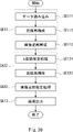
- FIG. 4 is a flowchart of processing of the image processing apparatus according to the first embodiment
- FIG. 4 is a diagram showing an outline of reading of k-space raw data by a data acquisition unit
- FIG. 4 is a diagram schematically showing the configuration of an image processing device in which a data acquisition unit has a function of interpolating low-density k-space raw data
- FIG. 10 is a flow chart of a processing procedure of step SE11;
- FIG. 4 is a diagram showing data flow in the image processing apparatus according to the first embodiment
- FIG. FIG. 2 is a diagram schematically showing a configuration when the image processing apparatus according to Embodiment 1 has a learned model building function
- 4 is a flowchart of learning processing of the image processing apparatus according to the first embodiment
- It is a figure which shows the structure of MTANN and the outline
- FIG. 4 is a diagram schematically showing the configuration of an image processing device when an estimating section and a machine learning section are integrated
- FIG. 10 is a diagram showing an example of an image of a subject imaged by changing the imaging method
- FIG. 2 is a diagram schematically showing the configuration of an image processing apparatus according to a second embodiment
- FIG. 9 is a flowchart of processing in an estimation phase of the image processing apparatus according to the second embodiment
- FIG. 10 is a diagram showing the flow of data in the image processing apparatus according to the second embodiment
- FIG. FIG. 10 is a diagram schematically showing a configuration when the image processing apparatus according to the second embodiment has a learned model construction function
- 9 is a flowchart of learning processing of the image processing apparatus according to the second embodiment
- FIG. 11 is a diagram schematically showing the configuration of an image processing apparatus as a first configuration example according to a third embodiment
- FIG. 11 is a flowchart of processing in an estimation phase of the image processing apparatus as the first configuration example according to the third embodiment
- FIG. 12 is a diagram schematically showing the configuration of an image processing apparatus as a second configuration example according to the third embodiment;
- FIG. 12 is a flowchart of processing in an estimation phase of the image processing apparatus as the second configuration example according to the third embodiment;
- FIG. 11 is a diagram schematically showing the configuration of an image processing apparatus as a first configuration example according to a fourth embodiment;
- FIG. 12 is a flowchart of processing in an estimation phase of the image processing apparatus as the first configuration example according to the fourth embodiment;
- FIG. FIG. 12 is a diagram schematically showing the configuration of an image processing apparatus that is a second configuration example according to the fourth embodiment;
- FIG. 14 is a flowchart of processing in an estimation phase of the image processing apparatus that is the second configuration example according to the fourth embodiment;
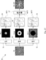
- FIG. 4 is a diagram schematically showing the configuration of a filter bank image output type estimation processing unit
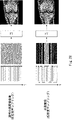
- FIG. 2 is a diagram showing an example of k-space raw data and reconstructed images when normal high-definition imaging and high-speed imaging are performed by an MRI apparatus;
- FIG. 1 is a diagram showing an example of a hardware configuration for realizing the image processing apparatus according to the first embodiment.
- the image processing apparatus 100 can be implemented by a computer 1000 such as a dedicated computer or a personal computer (PC). However, the computer does not need to be physically single, and multiple computers may be used when performing distributed processing.
- a computer 1000 has a CPU (Central Processing Unit) 1001, a ROM (Read Only Memory) 1002 and a RAM (Random Access Memory) 1003, which are interconnected via a bus 1004.
- a CPU Central Processing Unit
- ROM Read Only Memory
- RAM Random Access Memory
- An input/output interface 1005 is also connected to the bus 1004 .
- the input/output interface 1005 includes, for example, an input unit 1006 including a keyboard, mouse, sensors, etc., a display including a CRT, LCD, etc., an output unit 1007 including headphones, speakers, etc., a storage unit 1008 including a hard disk, etc.
- a communication unit 1009 including a modem, a terminal adapter, etc. is connected.
- the CPU 1001 executes various kinds of processing according to various programs stored in the ROM 1002 or various programs loaded from the storage unit 1008 to the RAM 1003. In this embodiment, for example, processing of each unit of the image processing apparatus 100, which will be described later. .
- a GPU Graphics Processing Unit
- a GPU Graphics Processing Unit
- processing of each unit of the image processing apparatus 100 may be performed.
- the GPU is suitable for performing routine processing in parallel, and by applying it to processing in a neural network, which will be described later, and the like, it is possible to improve the processing speed compared to the CPU 1001 .
- the RAM 1003 also stores data necessary for the CPU 1001 and GPU to execute various types of processing.
- the communication unit 1009 performs, for example, communication processing via the Internet (not shown), transmits data provided by the CPU 1001, and outputs data received from the communication partner to the CPU 1001, RAM 1003, and storage unit 1008.
- a storage unit 1008 communicates with the CPU 1001 to save and erase information.
- the communication unit 1009 also performs communication processing of analog signals or digital signals with other devices.
- the input/output interface 1005 is also connected to a drive 1010 as necessary, and for example, a magnetic disk 1011, an optical disk 1012, a flexible disk 1013, or a semiconductor memory 1014 is appropriately mounted, and a computer program read from them is required. is installed in the storage unit 1008 according to the
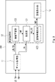
- FIG. 2 schematically shows the configuration of the image processing apparatus 100 according to the first embodiment.
- the image processing device has a data acquisition unit 11 , an estimation processing unit 12 and an image display unit 13 .
- FIG. 3 shows in more detail the configuration of the image processing apparatus 100 according to the first embodiment.
- FIG. 4 shows a flowchart of processing of the image processing apparatus 100 according to the first embodiment.
- the data acquisition unit 11 reads k-space raw data RD, which is raw data of the k-space captured at high speed by thinning out measurement points with an MRI apparatus.
- k-space raw data obtained by high-speed imaging by thinning measurement points in an MRI apparatus that is, by low-density sampling
- the data acquisition unit 11 outputs the read low-density sampling k-space raw data RD to the estimation processing unit 12 .
- the data acquisition unit 11 can appropriately read the low-density sampling k-space raw data RD from a storage device or an MRI apparatus (step SE11 in FIG. 4).
- FIG. 5 shows an overview of how the data acquisition unit 11 acquires k-space raw data.
- the storage device for example, the storage unit 1008 and the RAM 1003 described above can be used.
- the low-density sampling k-space raw data RD is stored in storage devices such as the storage unit 1008 and the RAM 1003, and can be read by the data acquisition unit 11 as appropriate. Also, the low-density sampling k-space raw data RD may be provided from the MRI apparatus 1200 to the data acquisition unit 11 .
- k-space raw data is given as input data IN from the data acquisition unit 11 to the estimation processing unit 12, the estimation processing performed by the estimation processing unit 12 or the learning processing described later must be performed smoothly and with high accuracy. It is desirable to provide k-space raw data obtained by interpolating the thinned-out measurement points instead of raw low-density sampling k-space raw data RD that has been thinned out and captured at high speed. Therefore, it is desirable that the data acquisition unit 11 have a function of interpolating the thinned-out measurement points in the low-density sampling k-space raw data RD.
- FIG. 6 schematically shows the configuration of the image processing device 100 when the data acquisition unit has an interpolation function for low-density sampling k-space raw data RD.
- FIG. 7 shows a flowchart of the processing procedure of step SE11.
- the data acquisition unit 11 has a data reading unit 111 , an image reconstruction unit 112 and an image reverse reconstruction unit 113 .
- the image reconstruction unit 112 and the image inverse reconstruction unit 113 constitute a data interpolation unit that interpolates the thinned measurement points in the low-density sampling k-space raw data RD.
- the data reading unit 111 is configured to read data such as low-density sampling k-space raw data RD (step SE111 in FIG. 7).
- the image reconstruction unit 112 Fourier-transforms the low-density sampling k-space raw data RD to reconstruct interpolated image data IMG_PRE (step SE112 in FIG. 7).
- the image inverse reconstruction unit 113 performs an inverse Fourier transform on the interpolated image data IMG_PRE to obtain interpolated k-space raw data RD_PRE, and outputs the interpolated k-space raw data RD_PRE to the estimation processing unit 12 as input data IN. (Step SE113 in FIG. 7).
- FIG. 8 shows the data flow in the image processing apparatus 100 according to the first embodiment.
- the vertical axis represents phase encoding
- the horizontal axis represents frequency encoding.
- interpolated image data IMG_PRE which is a low-resolution image accompanied by image quality deterioration due to missing measurement points.
- the image inverse reconstruction unit 113 the interpolated k-space raw data RD_PRE obtained by expanding the phase encoding and frequency encoding information of the interpolated image data IMG_PRE into the k-space is acquired. be done.
- the interpolated k-space raw data RD_PRE reflects the phase-encoding and frequency-encoding information of the low-resolution interpolated image data IMG_PRE, but data without missing measurement points is obtained.
- the missing measurement points can be interpolated by sequentially performing the image reconstruction processing and the image inverse transformation processing on the k-space raw data from which the measurement points have been thinned out.
- sampling can be skipped at regular intervals, but in order to collect low-density data more efficiently and effectively, areas with higher image information and image energy are sampled at higher densities, and other areas are sampled at lower densities. It is also densely sampled.
- a low-frequency region that is, near the center of the k-space coordinates, is sampled at a high density because there is much image energy and information, and a high-frequency region away from the center is sampled at a low density.
- the estimation processing unit 12 has an estimation unit 121 and an image reconstruction unit 122, and performs processing in the procedure of step SE12 including steps SE121 and SE122.
- the estimating unit 121 holds a trained model constructed in advance, and applies low-density sampling k-space raw data RD or interpolated k-space raw data RD_PRE as input data IN to be analyzed to the held trained model.
- estimated k-space raw data RD_ES estimated based on the learning result is output (step SE121 in FIG. 4).
- the estimation here means outputting data whose image quality has been restored by inputting input data corresponding to a low image quality image to a trained model.
- the image reconstruction unit 122 Fourier-transforms the estimated k-space raw data RD_ES to reconstruct restored image data IMG of the subject with improved image quality.
- the reconstructed restored image data IMG is output to the image display unit 13 (step SE122 in FIG. 4).
- estimation processing unit 12 is also called a k-space estimation processing unit because k-space raw data is input as input data and estimation processing is performed.
- the estimation unit 121 may receive information INF indicating the learned model from an external storage device or the like, and hold the learned model based on the received information INF indicating the learned model.
- the information INF may be provided in the form of, for example, parameters that define weighting coefficients between neurons of a neural network that constitutes a trained model.
- the image display unit 13 displays images used for diagnosis on a display device such as a display based on the restored image data IMG received from the estimation processing unit 12 (step SE13 in FIG. 4).
- a display device such as a display based on the restored image data IMG received from the estimation processing unit 12 (step SE13 in FIG. 4).
- the output unit 1007 described above may be used.
- FIG. 9 schematically shows a configuration when the image processing apparatus 100 according to Embodiment 1 has a learned model construction function.
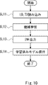
- FIG. 10 shows a flowchart of learning processing of the image processing apparatus 100 according to the first embodiment.
- the estimation processing section 12 further has a machine learning section 123 .
- the machine learning unit 123 is configured to learn data read from the storage device by supervised learning in the learning phase.
- the data acquisition unit 11 reads learning data LD captured in advance by the MRI apparatus and teacher data TD, which are stored in a storage device such as the RAM 1003 or the storage unit 1008, and outputs them to the machine learning unit 123. (Step SL11 in FIG. 10).
- the machine learning unit 123 inputs the received learning data LD and teacher data TD to the neural network to perform machine learning by deep learning (step SL12 in FIG. 10).
- the learning data LD is low-density sampling k-space raw data obtained by thinning out measurement points in advance and high-speed imaging of the subject.
- the teacher data TD is high-density sampling k-space raw data obtained by high-definition imaging of a subject without thinning out measurement points in advance.
- image output type deep learning is a method for directly learning images such as image output type deep learning.
- image output type deep learning is MTANN (Massive-Training Artificial Neural Network).
- MTANN is a non-linear deep learning model that can output images.
- the machine learning unit 123 learns a trained model (estimator) acquired by MTANN.
- MTANN is described in Patent Documents 4 and 5, but will be briefly described below.
- MTANN is a neural network applicable to various image processing and pattern recognition processing.
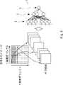
- FIG. 11 shows an overview of the MTANN structure and data input to the MTANN.
- the MTANN 1 is composed of a multilayer neural network (ANN: Artificial Neural Network) that can directly manipulate input pixel levels and output pixel levels.
- ANN Artificial Neural Network
- the multi-layer ANN of MTANN1 is composed of an input layer 2, a hidden layer 3 and an output layer 4.
- the input layer 2 and hidden layer 3 have multiple units (neurons), but the output layer 4 has only one unit (neuron).
- the input layer 2, hidden layer 3, and output layer 4 each have a linear function, a sigmoid function, and a linear function as activation functions. Since the performance of ANN in image processing is greatly improved by making the activation function of the output layer a linear function, in MTANN, a linear function is applied instead of the sigmoid function as the activation function of the units of the output layer. be.
- MTANN1 performs various functions such as high-pass filtering, low-pass filtering, band-pass filtering, noise reduction, edge enhancement, edge detection, interpolation, pattern matching, object enhancement, object recognition, wavelet transform, texture analysis by Fourier transform, and segmentation. By learning the function of filtering, it is possible to perform image processing and pattern recognition. This allows MTANN 1 to approximately implement any mapping process.
- the pixel values of the input image are normalized. For example, when the quantization level of the pixel value of the input image is 10 bits (1024 gradations), if the pixel value is 0 (the lower limit of the dynamic range), the pixel value is 0, and the pixel value is 1023 (the upper limit of the dynamic range). The pixel value is normalized so that it is 1 if . This normalization is an example, and other normalization methods may be performed.
- the image input to MTANN 1 is performed by sequentially inputting subregions obtained by scanning the original input image with a local window RS having a predetermined size.
- the input image is scanned by repeating the process of shifting the local window RS by one pixel from one end of the pixel row and shifting to the next row when the other end is reached. That is, the local windows are shifted by one pixel while having overlap.
- a sub-region can be cut out from one sheet of input data, and the included pixel values can be normalized before being input to the MTANN1.
- the pixel value f(x, y) output from MTANN1 is a continuous value corresponding to the central pixel value of the local window RS and is represented by the following equation.
- x and y are coordinate values of the image
- NN ⁇ * ⁇ is the output of the modified ANN
- I(x, y) is the input vector to the modified ANN
- g(x, y) is the local window R is the normalized pixel value in S.
- the pixel value f(x,y) of the output image ie the output value of the MTANN, is output as an estimate of the desired value depending on the application.
- the estimated pixel value of the high-quality image is output as the pixel value f(x, y).
- the pixel value f(x, y) is output as a “likelihood indicating likelihood of a lesion”.
- MTANN1 is trained by performing supervised learning using training data, as disclosed in US Pat. Then, by inputting an input image to be diagnosed to the trained MTANN , the estimated pixel values described above are obtained for each local window RS. Then, a desired output image can be obtained based on the information of the local window obtained from the input image.
- identifying whether or not an image contains a lesion it is possible to determine whether or not an input image to be diagnosed contains a lesion based on the pixel values obtained from one input image to be diagnosed. becomes.
- General machine learning techniques can be applied to operations in the learning phase (that is, the learning method) and the execution phase when using MTANN.
- the techniques in Patent Documents 4 and 5 can be used.
- a learned model can be constructed by inputting input data for learning and teacher data into a network configured by an MTANN and performing supervised machine learning.
- Applicable deep learning methods are not limited to MTANN, and include convolutional neural networks (CNN), shift-invariant neural networks, deep belief networks (DBN), deep neural networks (DNN), fully convolutional neural networks (FCN), U-Net, V-Net, multi-resolution massive-training artificial neural networks, multiple expert massive-training artificial neural networks, SegNet, VGG-16, LeNet, AlexNet, Residual network (ResNet), Auto encoders Various deep learning techniques such as and decoders, Generative adversarial networks (GAN), Recurrent Neural Networks (RNN), Recursive Neural Networks, Long Short-Term Memory (LSTM) can also be used.
- CNN convolutional neural networks
- DNN deep belief networks
- DNN deep neural networks
- FCN fully convolutional neural networks
- U-Net deep neural networks
- V-Net multi-resolution massive-training artificial neural networks
- SegNet VGG-16
- LeNet LeNet
- AlexNet Residual network
- ResNet Residual
- the machine learning unit 123 sequentially inputs pairs of learning data LD and teacher data TD linked to the learning data LD and learns by supervised learning, thereby obtaining weighting coefficients (or , parameters of the machine learning model) to build a trained model.
- the machine learning unit 123 may output information INF for building a trained model to the estimation unit 121 (step SL13 in FIG. 10). As a result, the estimation unit 121 can hold the trained model based on the received information INF (step SL14 in FIG. 10).
- FIG. 12 schematically shows the configuration of the image processing apparatus 100 when the estimating section and the machine learning section are integrated.
- a learning estimation unit 124 that integrates the estimation unit 121 and the machine learning unit 123 is provided.
- a learned model constructed by machine learning can be used as it is in the estimation phase.
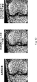
- FIG. 13 shows an example of an image of a subject imaged by changing the imaging method.
- the image on the left side is a high-definition image obtained by reconstructing high-density sampling k-space raw data obtained by imaging a subject using a normal imaging method with an MRI apparatus.
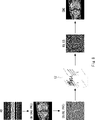
- the center image is a high-speed captured image obtained by reconstructing low-density sampling k-space raw data obtained by high-speed imaging eight times faster than normal high-definition imaging, as a comparative example.
- the image on the right is restored image data whose image quality has been restored, obtained by estimating the low-density sampling k-space raw data image obtained by high-speed imaging in the central comparative example with the image processing apparatus 100.
- 10 is a recovered image displaying IMG;
- the high-speed image which is the comparative example in the center, was captured at an excessively high speed, resulting in a decrease in the resolution of the reconstructed image, an increase in artifacts, an increase in noise, etc., resulting in tissue damage compared to the high-definition image on the left.
- the boundaries of the joints are greatly blurred, making it difficult to interpret the condition of the joints in particular. Therefore, it can be considered inappropriate as an image used for diagnosis of a subject.
- tissue enhancement is clearer than in the high-speed captured image in the center.
- the image quality is lower than the high-definition image on the left, the images are clear enough to read the condition of the joints. can.
- the images obtained by the image processing apparatus 100 have high resolution and high spatial resolution, well delineated tissue details, reduced noise and artifacts, high signal-to-noise ratios, and rich in useful diagnostic information. It can be seen that it is a high-density sample reconstructed image.
- the imaging time that can be shortened is about 1/2.
- the imaging time of the MRI apparatus which is generally about several tens of minutes, can be reduced to a few minutes, for example, 1/8, so that it is possible to acquire an image that can be used for diagnosis in a few minutes. is.
- the throughput of the MRI apparatus can be significantly improved compared to general high-speed imaging techniques.
- the imaging time of the MRI apparatus can be reduced to about several minutes, so that throughput similar to that of other examination apparatuses such as CT (Computed Tomography) apparatus can be realized.
- CT Computerputed Tomography
- the image processing apparatus 100 obtains an image by reconstructing the estimated k-space raw data RD_ES obtained by inputting the low-density sampling k-space raw data RD to the estimation processing unit 12, and obtaining an image.
- the target data is not limited to k-space raw data, and may be image data obtained by reconstructing k-space raw data. Therefore, in the present embodiment, an image processing apparatus that inputs image data to an estimation processing unit and performs estimation processing will be described.
- FIG. 14 schematically shows the configuration of the image processing device 200 according to the second embodiment.
- FIG. 15 shows a flowchart of processing in the estimation phase of the image processing apparatus 200 according to the second embodiment.
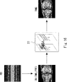
- FIG. 16 shows the data flow in the image processing apparatus 200 according to the second embodiment.
- the image processing apparatus 200 has a configuration in which the data acquisition section 11 and the estimation processing section 12 of the image processing apparatus 100 according to the first embodiment are replaced with a data acquisition section 21 and an estimation processing section 22, respectively.
- the data acquisition unit 21 has a configuration obtained by removing the image inverse reconstruction unit 113 from the data acquisition unit 11 of the image processing apparatus 100 in FIG. 6, and performs the processing of step SE21 (steps SE211 and SE212) in FIG.
- the data reading unit 111 reads the low-density sampling k-space raw data RD (step SE211 in FIG. 15), as in the first embodiment.
- the image reconstruction unit 112 Fourier-transforms the low-density sampling k-space raw data RD to reconstruct interpolated image data IMG_PRE, and outputs the interpolated image data IMG_PRE to the estimation processing unit 22 as input data IN (FIG. 15 step SE212).
- Other operations of the data reading unit 111 and the image reconstructing unit 112 are the same as those of the image processing apparatus 100, so description thereof will be omitted.
- the estimation processing unit 22 has at least an estimation unit 221 .
- the estimating unit 221 holds a pre-constructed learned model, and the interpolated image data IMG_PRE reconstructed as input data IN to be analyzed is input to the held learned model, and performs estimation processing. As a result, the restored image data IMG whose image quality has been restored is output (step SE22 in FIG. 15).
- estimation processing unit 22 is also called an image space estimation processing unit because image data is input as input data and estimation processing is performed.
- the image display unit 13 displays an image used for diagnosis on a display device such as a display based on the received restored image data IMG (step SE23 in FIG. 15).
- FIG. 17 schematically shows a configuration when the image processing apparatus 200 according to the second embodiment has a learned model construction function.
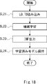
- FIG. 18 shows a flowchart of learning processing of the image processing apparatus 200 according to the second embodiment.
- the estimation processing section 22 further has a machine learning section 223 .
- the machine learning unit 223 is configured to learn data read from the storage device by supervised learning in the learning phase.
- the data acquisition unit 21 reads learning data LD captured in advance by the MRI apparatus and teacher data TD, which are stored in storage devices such as the RAM 1003 and the storage unit 1008 .
- the data acquisition unit 21 reconstructs the learning data LD and the teacher data TD, which are k-space image data, into the learning data image IMG_LD and the teacher image data IMG_TD, which are image data, by the image reconstruction unit 212, and the estimation processing unit 22 (step SL21 in FIG. 18).
- the machine learning unit 223 inputs the learning image data IMG_LD and the teacher image data IMG_TD to the neural network to perform machine learning by deep learning (step SL22 in FIG. 18). Also in this embodiment. Training can be done using a variety of deep learning techniques, including MTANN.
- the machine learning unit 223 may output information INF for constructing a learned model to the estimation unit 221 (step SL23 in FIG. 19). Thereby, the estimation unit 221 can hold the learned model based on the received information INF (step SL24 in FIG. 19).
- the estimation unit 221 may receive information INF prepared in advance from an external storage device or the like, or a learning estimation unit that integrates an estimation unit and a machine learning unit, as in the first embodiment. may be provided for learning and estimation.
- Embodiment 1 it is possible to significantly improve the throughput of the MRI apparatus compared to general high-speed imaging techniques. As a result, the imaging time of the MRI apparatus can be reduced to about several minutes, so that throughput similar to that of other examination apparatuses such as CT (Computed Tomography) apparatus can be realized. In addition, it is possible to significantly reduce the burden on the subject by shortening the imaging time.
- CT Computerputed Tomography
- Embodiment 3 Embodiments 1 and 2 have described examples in which the estimation process is performed only once on input data. However, it is possible to improve the image quality of the restored image data IMG, which is the final output result, by performing the estimation process in multiple stages. In this embodiment, an image processing apparatus capable of performing multistage estimation processing will be described.
- FIG. 19 schematically shows the configuration of an image processing apparatus 300 as a first configuration example according to the third embodiment.
- FIG. 20 shows a flowchart of processing in the estimation phase of the image processing apparatus 300 as the first configuration example according to the third embodiment.
- the image processing device 300 has a data acquisition unit 11 , a k-space estimation processing unit 32A, an image space estimation processing unit 32B, and an image display unit 13 .
- the k-space estimation processing unit 32A has the same configuration as the estimation processing unit 12 of the image processing device 100, and performs the processing of step SA32 (steps SE121 and SE122) in FIG.
- the low-density sampled k-space raw data RD or the interpolated k-space raw data RD_PRE which is the input data IN from the data acquisition unit 11
- the estimation unit 121 performs the estimated k-space Output raw data RD_ES.
- the image reconstruction unit 122 reconstructs the estimated k-space raw data RD_ES into estimated image data IMG_ES, and outputs the estimated image data IMG_ES to the image space estimation processing unit 32B (step SA32 in FIG. 20).
- the image space estimation processing unit 32B has the same configuration as the estimation processing unit 22 of the image processing device 200.
- the image space estimation processing unit 32B receives the estimated image data IMG_ES as input data, and outputs the restored image data IMG, which is the estimation result, to the image display unit 13 (step SB32 in FIG. 20).
- the subsequent configuration and operation of the image processing device 300 are the same as those of the image processing device 100, so description thereof will be omitted.
- the second-stage estimation processing in the image space can be performed after performing the first-stage estimation processing in the k-space. This makes it possible to further improve the image quality of the restored image data IMG obtained as the final estimation result.
- FIG. 21 schematically shows the configuration of an image processing apparatus 310 as a second configuration example according to the third embodiment.
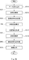
- FIG. 22 shows a flowchart of processing in the estimation phase of the image processing apparatus 310 as the second configuration example according to the third embodiment.
- the image processing device 310 has a data acquisition section 21 , an image space estimation processing section 32 C, a k-space estimation processing section 32 D, an image reverse reconstruction section 34 and an image display section 13 .
- the image space estimation processing unit 32C has the same configuration as the estimation processing unit 22 of the image processing device 200.
- the image space estimation processing unit 32C receives the interpolated image data IMG_PRE as input data, and outputs estimated intermediate image data IMG_ES0, which is the estimation result, to the image inverse reconstruction unit 34 (step SC32 in FIG. 22).
- the image inverse reconstruction unit 34 Fourier-transforms the estimated intermediate image data IMG_ES0 to obtain intermediate k-space raw data RD_ES0, and outputs the intermediate k-space raw data RD_ES0 to the k-space estimation processing unit 32D (step S34 in FIG. 22). ).
- the k-space estimation processing unit 32D has the same configuration as the estimation processing unit 12 of the image processing device 100, and performs the processing of step SD32 (steps IMG_ES0 to SE121 and SE122) in FIG.
- the intermediate k-space raw data RD_ES0 is input to the estimation unit 121, and the estimation unit 121 outputs estimated k-space raw data RD_ES, which is the estimation result.
- the image reconstruction unit 122 reconstructs the estimated k-space raw data RD_ES into the restored image data IMG, and outputs the restored image data IMG to the image display unit 13 (step SD32 in FIG. 22).
- the subsequent configuration and operation of the image processing device 310 are the same as those of the image processing device 200, so description thereof will be omitted.
- the second-stage estimation processing in the k-space can be performed. This makes it possible to further improve the image quality of the restored image data IMG obtained as the final estimation result.
- the two-step estimation process may be repeated.
- two or more iterative estimation processing units 301 each including the k-space estimation processing unit 32A and the image space estimation processing unit 32B may be arranged in series between the data acquisition unit 11 and the image display unit 13 . This makes it possible to repeat the two-step estimation process performed by the image processing apparatus 300 a plurality of times.
- an image inverse reconstruction unit similar to the image inverse reconstruction unit 34 is inserted between two adjacent iterative estimation processing units 301. do it.
- Two or more iterative estimation processing units 311 consisting of an image space estimation processing unit 32C, a k-space estimation processing unit 32D, and an image inverse reconstruction unit 34 are arranged in series between the data acquisition unit 21 and the image display unit 13. You may
- the iterative estimation processing unit 301 and the iterative estimation processing unit 311 may be arranged alternately or randomly in series.
- the iterative estimation processing unit 301 is arranged after the iterative estimation processing unit 301 or 311, in order to input k-space raw data to the iterative estimation processing unit 301 in the latter stage, the iterative estimation processing unit 301 or 311 in the previous stage and the iterative estimation processing unit 311 in the latter stage
- An image inverse reconstruction unit similar to the image inverse reconstruction unit 34 may be inserted between the estimation processing unit 301 and the estimation processing unit 301 .
- the leading iterative estimation processing unit is the iterative estimation processing unit 301
- input data is input by the data acquisition unit 11, and when the leading iterative estimation processing unit is the iterative estimation processing unit 311, the data acquisition unit 21 to input the input data.
- the image quality of the finally obtained image data can be further improved by performing the estimation process multiple times.
- Embodiment 4 In the third embodiment, an example in which the estimation process is performed an even number of times on input data has been described. However, the estimation process may be performed only an odd number of times of 3 or more. In this embodiment, an image processing apparatus capable of performing the estimation process an odd number of times, ie, three times or more, will be described.
- FIG. 23 schematically shows the configuration of an image processing apparatus 400 as a first configuration example according to the fourth embodiment.
- FIG. 24 shows a flowchart of processing in the estimation phase of the image processing apparatus 400 as the first configuration example according to the fourth embodiment.
- the image processing apparatus 400 has a configuration in which an image inverse reconstruction unit 44 and a k-space estimation processing unit 42A are added to the image processing apparatus 300 according to the third embodiment.
- the k-space estimation processing unit 32A outputs estimated image data IMG_ES1 as an estimation result.
- Image space estimation processing section 32B outputs estimated image data IMG_ES2 to image inverse reconstruction section 44 as an estimation result corresponding to estimated image data IMG_ES1, which is input data.
- the image inverse reconstruction unit 44 obtains k-space raw data RD_ES2 by inverse Fourier transforming the estimated image data IMG_ES2, and outputs the estimated k-space raw data RD_ES2 to the k-space estimation processing unit 42A (step S44 in FIG. 24). .
- the k-space estimation processing unit 42A has the same configuration as the estimation processing unit 12 of the image processing device 100, and performs the processing of step SA42 (steps SE121 and SE122) in FIG.
- the estimation unit 121 of the k-space estimation processing unit 42A outputs k-space raw data RD_ES3, which is an estimation result according to the estimated k-space raw data RD_ES2.
- the image reconstruction unit 122 reconstructs the estimated k-space raw data RD_ES3 and outputs the restored image data IMG, which is the final estimation result, to the image display unit 13 (step SA42 in FIG. 22).
- the subsequent configuration and operation of the image processing device 400 are the same as those of the image processing device 300, so description thereof will be omitted.
- the first-stage estimation processing in the k-space, the second-stage estimation processing in the image space, and the third-stage estimation processing in the k-space are performed, and the final estimation result is the recovery
- the finished image data IMG can be obtained. Therefore, it is possible to further improve the image quality of the restored image data IMG through multistage estimation processing.
- FIG. 25 schematically shows the configuration of an image processing apparatus 410 as a second configuration example according to the fourth embodiment.
- FIG. 26 shows a flowchart of processing in the estimation phase of the image processing apparatus 410 as the second configuration example according to the fourth embodiment.
- the image processing device 410 has a configuration in which an image space estimation processing unit 42B is added to the image processing device 310 according to the third embodiment.
- the k-space estimation processing unit 32D outputs the estimated image data IMG_ES3 to the image space estimation processing unit 42B.
- the image space estimation processing unit 42B has the same configuration as the estimation processing unit 22 of the image processing device 200.
- the image space estimation processing unit 42B outputs the restored image data IMG, which is the estimation result according to the estimated image data IMG_ES3, to the image display unit 13 (step SB42 in FIG. 26).
- the subsequent configuration and operation of the image processing device 410 are the same as those of the image processing device 310, so description thereof will be omitted.
- the two-step estimation process may be repeatedly performed.
- two or more iterative estimation processing units 401 consisting of a k-space estimation processing unit 32A, an image space estimation processing unit 32B, and a k-space estimation processing unit 42A are serially installed between the data acquisition unit 11 and the image display unit 13.
- an image inverse reconstruction unit similar to the image inverse reconstruction unit 44 is inserted between two adjacent iterative estimation processing units 401. do it.
- Two or more iterative estimation processing units 411 each consisting of an image space estimation processing unit 32C, a k-space estimation processing unit 32D, and an image space estimation processing unit 42B are arranged in series between the data acquisition unit 21 and the image display unit 13. You may
- the iterative estimation processing unit 401 and the iterative estimation processing unit 411 may be arranged alternately or randomly in series.
- the iterative estimation processing unit 401 is arranged after the iterative estimation processing unit 401 or 411, in order to input k-space raw data to the iterative estimation processing unit 401 in the latter stage, the iterative estimation processing unit 401 or 411 in the previous stage and the iterative estimation processing unit 401 in the latter stage are used.
- An image inverse reconstruction unit similar to the image inverse reconstruction unit 44 may be inserted between the estimation processing unit 401 and the estimation processing unit 401 .
- the image processing apparatus by performing the estimation process multiple times, it is possible to further improve the image quality of the finally obtained image data, as in the case of the third embodiment.
- the present invention is not limited to the above-described embodiments, and can be modified as appropriate without departing from the scope of the invention.
- the iterative estimation processing units 301 and 311 according to the third embodiment and the iterative estimation processing units 401 and 411 according to the fourth embodiment may be arranged alternately or randomly.
- the iterative estimation processing unit 301 or 401 when the iterative estimation processing unit 301 or 401 is arranged after the iterative estimation processing unit 301, 311, 311 or 411, the iterative estimation processing unit (the iterative estimation processing unit 301, 311, 301 or 401) arranged in the preceding stage and the iterative estimation processing unit (iterative estimation processing unit 311 or 411) arranged in the subsequent stage, an image inverse reconstruction unit similar to the image inverse reconstruction unit 34 or 44 may be inserted.
- leading iterative estimation processing unit is the iterative estimation processing unit 301 or 401
- input data is input by the data acquisition unit 11
- the leading iterative estimation processing unit is the iterative estimation processing unit 311 or 411
- the input data may be input by the data acquisition unit 21 .
- Embodiments 3 and 4 can be interpreted as follows. That is, as the estimation processing unit, one or more k-space estimation processing units and one or more image space estimation processing units arranged in series may be used. In this case, when the k-space estimation processing unit is arranged after the k-space estimation processing unit or the image space estimation processing unit, the preceding k-space estimation processing unit or image space estimation processing unit and the subsequent k-space estimation processing The image data output from the preceding k-space estimation processing unit or the image space estimation processing unit is inversely Fourier-transformed and the inversely reconstructed k-space raw data is transferred to the subsequent k-space. It is sufficient to output to the estimation processing unit.
- the data acquisition unit uses thinned measurement of low-density sampling k-space raw data.
- the interpolated k-space raw data may be converted into interpolated k-space raw data obtained by interpolating the points, and the interpolated k-space raw data may be output to the leading k-space estimation processing unit as the input data.
- the data acquisition unit obtains interpolated image data obtained by Fourier transforming low-density sampling k-space raw data. is output as input data to the first image space estimation processing unit.
- the above-described estimation processing unit may be configured as a filter bank image output type estimation processing unit in which a plurality of processing lines having k-space raw data as input data are arranged in parallel.
- FIG. 27 schematically shows the configuration of the filter bank image output type estimation processing unit 50 .
- the estimation processing unit 50 has a low-pass filter (LPF) 51 , a band-pass filter (BPF) 52 , a high-pass filter (HPF) 53 , learning estimation units 54 to 56 and a coupling layer 57 .
- LPF low-pass filter
- BPF band-pass filter
- HPF high-pass filter
- the input data IN is interpolated k-space raw data and is input to the LPF 51, BPF 52 and HPF 53.
- the LPF 51 passes the low frequency band IN_L of the input data IN to the learning estimation unit 54
- the BPF 52 passes the middle frequency band IN_M of the input data IN to the learning estimation unit 55
- the HPF 53 learns the high frequency band IN_H of the input data IN. It is passed to the estimator 56 . Since the k-space is already a frequency space, these frequency band limiting processes can be realized by multiplying the k-space image with a two-dimensional or three-dimensional function with 1 for the band to be limited and 0 for the others.
- the learning estimation units 54 to 56 can perform one or both of the estimation process and the learning process using the frequency components of the input data IN.
- the processed k-space raw data OUT1 to OUT3 output by the learning estimation units 54 to 56 are output to the coupling layer 57 .
- the combining layer 57 can combine the k-space raw data OUT1 to OUT3 to output k-space raw data RD_OUT corresponding to the entire frequency range.
- processing is performed by a learning estimation unit (it goes without saying that the estimation unit or the learning unit may be used) that performs processing specialized for the divided frequency bands, so that more accurate k-space generation can be performed. Data can be output.
- the present invention has been described mainly as a hardware configuration, but it is not limited to this, and arbitrary processing can be realized by causing a CPU (Central Processing Unit) to execute a computer program. It is also possible to In this case, the computer program can be stored and provided to the computer using various types of non-transitory computer readable medium.
- Non-transitory computer-readable media include various types of tangible storage media.
- non-transitory computer-readable media examples include magnetic recording media (eg, flexible discs, magnetic tapes, hard disk drives), magneto-optical recording media (eg, magneto-optical discs), CD-ROMs (Read Only Memory), CD-Rs, CD-R/W, semiconductor memory (eg, mask ROM, PROM (Programmable ROM), EPROM (Erasable PROM), flash ROM, RAM (random access memory)).
- the program may also be supplied to the computer on various types of transitory computer readable medium. Examples of transitory computer-readable media include electrical signals, optical signals, and electromagnetic waves. Transitory computer-readable media can deliver the program to the computer via wired channels, such as wires and optical fibers, or wireless channels.
Landscapes
- Physics & Mathematics (AREA)
- Health & Medical Sciences (AREA)
- General Physics & Mathematics (AREA)
- Life Sciences & Earth Sciences (AREA)
- Engineering & Computer Science (AREA)
- High Energy & Nuclear Physics (AREA)
- Theoretical Computer Science (AREA)
- Pathology (AREA)
- General Health & Medical Sciences (AREA)
- Nuclear Medicine, Radiotherapy & Molecular Imaging (AREA)
- Medical Informatics (AREA)
- Chemical & Material Sciences (AREA)
- Biomedical Technology (AREA)
- Heart & Thoracic Surgery (AREA)
- Radiology & Medical Imaging (AREA)
- Molecular Biology (AREA)
- Surgery (AREA)
- Animal Behavior & Ethology (AREA)
- Condensed Matter Physics & Semiconductors (AREA)
- Public Health (AREA)
- Veterinary Medicine (AREA)
- Biophysics (AREA)
- Analytical Chemistry (AREA)
- Biochemistry (AREA)
- Immunology (AREA)
- Magnetic Resonance Imaging Apparatus (AREA)
- Algebra (AREA)
- Mathematical Analysis (AREA)
- Mathematical Optimization (AREA)
- Mathematical Physics (AREA)
- Pure & Applied Mathematics (AREA)
Abstract
本開示は、MRI装置の撮像時間を短縮しつつ高画質の画像を取得することができる。データ取得部(11)は、MRI装置にて計測点を間引いて被検体を撮像することで得られた低密度サンプリングk空間生データを取得し、低密度サンプリングk空間生データに基づく入力データ(IN)を出力する。推定処理部(12)は、入力データ(IN)を学習済みモデルに入力することで推定処理を行い、間引かれた計測点により低下した画質が回復された回復済み画像データ(IMG)を出力する。画像表示部(13)は、回復済み画像データ(IMG)を表示する。
Description
本開示は、画像処理装置、画像処理方法及びプログラムが格納された非一時的なコンピュータ可読媒体に関する。
核磁気共鳴イメージング(MRI:Magnetic Resonance Imaging)装置は、被検体である生体、例えば人体の組織に磁場を印加し、そのときに生じる核磁気共鳴(NMR:Nuclear Magnetic Resonance)現象を利用して、2次元又は3次元の画像情報を取得する装置である。MRI装置は、CT(Computed Tomography)装置では撮影できない組織を撮影でき、かつ、放射線被曝が無いなど優れた特長を有している。
MRIでは、撮像時のNMR信号の読み取りにおいて、被検体に傾斜磁場を印加し位置のエンコードを行い、計測空間であるk空間における生データの集合として撮像データが取得される。k空間と実空間とは互いにフーリエ変換の関係にあるので、k空間での撮像データをフーリエ変換することで、実空間での画像が再構成される(特許文献1~3)。
MRI装置での被検体の撮像は比較的長時間を要し、一般的には数十分の撮像時間を要する。そのため、撮像に長時間を要することによる被検体の負担の軽減やMRI装置での撮像のスループット向上を図るため、k空間の計測点を間引いてサンプリングし、計測点間の未計測データを補間して画像の解像度を補償する高速撮像手法が用いられる。高速撮像手法としては、例えば、圧縮センシング法(Compressed Sensing)がある。その他の高速撮像手法としては、例えば、FSE(Fast Spin Echo)法、EPI(Echo Planner Imaging)法及びGE(Gradient Echo)法などが知られている。
しかし、上述した一般的な高速撮像手法では、間引くことが可能な計測点の割合には限界が有るため、通常の撮像時と比べて、短縮できる撮像時間は50%程度に過ぎない。よって、スループットを大幅に向上させることは原理的に困難である。
また、計測点を間引いたことにより、再構成した画像の分解能の低下、アーティファクトの増加、ノイズの増加などが生じるという問題が有り、その結果、画像の画質低下の原因ともなる。
図28に、MRI装置によって通常の高精細撮像及び高速撮像を行ったときのk空間生データと再構成した画像の例を示す。k空間の生データの表示においては、縦軸に位相エンコード、横軸に周波数エンコードをとっている。
上段の高精細撮像では、この例では、計測すべき位相エンコードの全範囲の計測を行っているため、そこから再構成した画像は精細な画像となっている。しかし、上述したように、計測点が多いために、撮像には比較的長時間を要する。
これに対し、下段の高速撮像では、sで表示した位置の撮像はスキップされており、k空間の生データにおいて黒塗りとなっている部分が、間引かれた計測点に対応する。この例では、高精細撮像と比べて、計測点がおおよそ1/2程度に削減されている。そこから再構成された画像は、間引き撮像による情報の欠落のため、高精細撮像の例と比べて、画質が劣化しアーティファクトが生じており、特に組織の境界が不鮮明になっていることが認められる。よって、画質が要求水準に満たない場合には、計測点を増加させるなどの措置が必要になり、高速撮像による撮像時間の削減はより制限されることとなる。
本開示の一態様である画像処理装置は、MRI装置にて計測点を間引いて被検体を撮像することで得られた低密度サンプリングk空間生データを取得し、前記低密度サンプリングk空間生データに基づく入力データを出力するデータ取得部と、前記入力データを学習済みモデルに入力することで推定処理を行い、間引かれた計測点により低下した画質が回復された回復済み画像データを出力する推定処理部と、前記回復済み画像データを表示する画像表示部と、を有するものである。これにより、間引かれた計測点により低下した入力データの画質を回復し、画質が回復された回復済み画像データに基づく高画質の画像を表示することができる。
本開示の一態様である画像処理装置は、上記の画像処理装置であって、前記データ取得部は、前記低密度サンプリングk空間生データの間引かれた計測点を補間した補間済みk空間生データに変換し、前記補間済みk空間生データを前記入力データとして前記推定処理部へ出力し、前記推定処理部は、前記補間済みk空間生データを前記学習済みモデルに入力することで推定処理を行い、前記間引かれた計測点により低下した画質が回復された推定k空間生データを出力し、前記推定k空間生データをフーリエ変換することで再構成した前記回復済み画像データを出力するk空間推定処理部として構成されることが望ましい。これにより、推定処理部に、k区間生データである入力データを適切に入力することができる。
本開示の一態様である画像処理装置は、上記の画像処理装置であって、前記データ取得部は、前記低密度サンプリングk空間生データをフーリエ変換することで再構成した画像データを逆フーリエ変換して逆再構成することで、前記補間済みk空間生データを取得することが望ましい。これにより、低密度サンプリングk空間生データを好適に補間することができる。
本開示の一態様である画像処理装置は、上記の画像処理装置であって、前記データ取得部は、前記低密度サンプリングk空間生データをフーリエ変換した画像データを前記入力データとして前記推定処理部へ出力し、前記推定処理部は、変換された前記画像データを前記学習済みモデルに入力することで推定処理を行い、前記間引かれた計測点により低下した画質が回復された前記回復済み画像データ出力する画像空間推定処理部として構成されることが望ましい。これにより、推定処理部に、画像データである入力データを適切に入力することができる。
本開示の一態様である画像処理装置は、上記の画像処理装置であって、前記推定処理部は、1つ以上のk空間推定処理部と1つ以上の画像空間推定処理部と、が直列的に配列され、前記k空間推定処理部は、入力データであるk空間生データを前記学習済みモデルに入力することで推定処理を行い、画質が回復されたk空間生データを出力し、前記k空間生データをフーリエ変換することで再構成した第2の画像データを出力し、前記画像空間推定処理部は、入力データである画像データを前記学習済みモデルに入力することで推定処理を行い、画質が回復された画像データを出力し、前記画像空間推定処理部の後段に前記k空間推定処理部が配置される場合には、前記画像空間推定処理部と前記k空間推定処理部との間に、前段の前記画像空間推定処理部が出力する画像データを逆フーリエ変換して逆再構成したk空間生データを、後段の前記k空間推定処理部へ出力する画像逆再構成部が設けられ、前記k空間推定処理部及び前記画像空間推定処理部の直列的な配列の最後尾から出力される画像データが前記回復済み画像データとして出力されることが望ましい。これにより、多段階の推定処理を行うことができ、回復済み画像データの画質をより向上させることが可能となる。
本開示の一態様である画像処理装置は、上記の画像処理装置であって、前記k空間推定処理部及び前記画像空間推定処理部の直列的な配列の先頭が前記k空間推定処理部である場合には、前記データ取得部は、前記低密度サンプリングk空間生データの間引かれた計測点を補間した補間済みk空間生データに変換し、前記補間済みk空間生データを前記入力データとして、先頭の前記k空間推定処理部へ出力し、前記k空間推定処理部及び前記画像空間推定処理部の直列的な配列の先頭が前記画像空間推定処理部である場合には、前記データ取得部は、前記低密度サンプリングk空間生データをフーリエ変換した画像データを前記入力データとして先頭の前記画像空間推定処理部へ出力することが望ましい。これにより、多段階の推定処理をおこなうときに、先頭の推定処理部に適切な形式の入力データを入力することができる。
本開示の一態様である画像処理装置は、上記の画像処理装置であって、前記データ取得部は、前記MRI装置にて計測点を間引いて前記被検体を撮像することで予め得られた低密度サンプリングk空間生データである学習データと、前記MRI装置にて計測点を間引くことなく前記被検体を撮像することで予め得られた高密度サンプリングk空間生データである教師データとを読み込み、読み込んだ前記学習データ及び前記教師データに基づく学習用入力データを前記推定処理部へ出力し、前記推定処理部は、前記学習用入力データに基づいた教師有り学習を行うことで、前記学習済みモデルを構築することが望ましい。これにより、推定処理に用いる学習済みモデルを好適に構築することができる。
本開示の一態様である画像処理装置は、上記の画像処理装置であって、前記データ取得部は、前記MRI装置にて計測点を間引いて前記被検体を撮像することで予め得られた低密度サンプリングk空間生データを再構成して得られた学習データと、前記MRI装置にて計測点を間引くことなく前記被検体を撮像することで予め得られた高密度サンプリングk空間生データを再構成して得られた教師データと、を読み込み、読み込んだ前記学習データ及び前記教師データに基づく学習用入力データを前記推定処理部へ出力し、前記推定処理部は、前記学習用入力データに基づいた教師有り学習を行うことで、前記学習済みモデルを構築することが望ましい。これにより、推定処理に用いる学習済みモデルを好適に構築することができる。
本開示の一態様である画像処理装置は、上記の画像処理装置であって、前記学習済みモデルは、MTANN(Massive-Training Artificial Neural Network)として構成されたネットワークに学習用データと教師データとを入力して学習を行うことで取得されたネットワークであることが望ましい。これにより、推定処理に用いる学習済みモデルを好適に構築することができる。
本開示の一態様である画像処理方法は、MRI装置にて計測点を間引いて被検体を撮像することで得られた低密度サンプリングk空間生データを取得し、前記低密度サンプリングk空間生データに基づく入力データを出力し、前記入力データを学習済みモデルに入力することで推定処理を行い、間引かれた計測点により低下した画質が回復された回復済み画像データを出力し、前記回復済み画像データを表示するものである。これにより、間引かれた計測点により低下した入力データの画質を回復し、画質が回復された回復済み画像データに基づく高画質の画像を表示することができる。
本開示の一態様であるプログラムは、MRI装置にて計測点を間引いて被検体を撮像することで得られた低密度サンプリングk空間生データを取得し、前記低密度サンプリングk空間生データに基づく入力データを出力する処理と、前記入力データを学習済みモデルに入力することで推定処理を行い、間引かれた計測点により低下した画質が回復された回復済み画像データを出力する処理と、前記回復済み画像データを表示する処理と、をコンピュータに実行させるものである。これにより、間引かれた計測点により低下した入力データの画質を回復し、画質が回復された回復済み画像データに基づく高画質の画像を表示することができる。
本開示によれば、MRI装置の撮像時間を短縮しつつ高画質の画像を取得することができる情報処理装置、情報処理方法及びプログラムを提供することができる。
以下、具体的な実施の形態について、図面を参照しながら詳細に説明する。ただし、以下の実施の形態に限定される訳ではない。また、説明を明確にするため、以下の記載及び図面は、適宜簡略化されている。また、同一の要素には、同一の符号を付し、重複する説明は省略する。
実施の形態1
まず、実施の形態1にかかる画像処理装置の理解の前提として、画像処理装置を実現するためのハードウェア構成の一例を示す。図1に、実施の形態1にかかる画像処理装置を実現するためのハードウェア構成の一例を示す図である。画像処理装置100は、専用コンピュータ、パーソナルコンピュータ(PC)などのコンピュータ1000により実現可能である。但し、コンピュータは、物理的に単一である必要はなく、分散処理を実行する場合には、複数であってもよい。図1に示すように、コンピュータ1000は、CPU(Central Processing Unit)1001、ROM(Read Only Memory)1002及びRAM(Random Access Memory)1003を有し、これらがバス1004を介して相互に接続されている。尚、コンピュータを動作させるためのOSソフトなどは、説明を省略するが、この画像処理装置を構築するコンピュータも当然有しているものとする。
まず、実施の形態1にかかる画像処理装置の理解の前提として、画像処理装置を実現するためのハードウェア構成の一例を示す。図1に、実施の形態1にかかる画像処理装置を実現するためのハードウェア構成の一例を示す図である。画像処理装置100は、専用コンピュータ、パーソナルコンピュータ(PC)などのコンピュータ1000により実現可能である。但し、コンピュータは、物理的に単一である必要はなく、分散処理を実行する場合には、複数であってもよい。図1に示すように、コンピュータ1000は、CPU(Central Processing Unit)1001、ROM(Read Only Memory)1002及びRAM(Random Access Memory)1003を有し、これらがバス1004を介して相互に接続されている。尚、コンピュータを動作させるためのOSソフトなどは、説明を省略するが、この画像処理装置を構築するコンピュータも当然有しているものとする。
バス1004には、入出力インターフェイス1005も接続されている。入出力インターフェイス1005には、例えば、キーボード、マウス、センサなどよりなる入力部1006、CRT、LCDなどよりなるディスプレイ、並びにヘッドフォンやスピーカなどよりなる出力部1007、ハードディスクなどより構成される記憶部1008、モデム、ターミナルアダプタなどより構成される通信部1009などが接続されている。
CPU1001は、ROM1002に記憶されている各種プログラム、又は記憶部1008からRAM1003にロードされた各種プログラムに従って各種の処理、本実施の形態においては、例えば後述する画像処理装置100の各部の処理を実行する。なお、GPU(Graphics Processing Unit)を設けて、CPU1001と同様に、ROM1002に記憶されている各種プログラム、又は記憶部1008からRAM1003にロードされた各種プログラムに従って各種の処理、本実施の形態においては、例えば後述する画像処理装置100の各部の処理を行ってもよい。なお、GPUは、定型的な処理を並列的に行う用途に適しており、後述するニューラルネットワークにおける処理などに適用することで、CPU1001に比べて処理速度を向上させることも可能である。RAM1003には又、CPU1001及びGPUが各種の処理を実行する上において必要なデータなども適宜記憶される。
通信部1009は、例えば図示しないインターネットを介しての通信処理を行ったり、CPU1001から提供されたデータを送信したり、通信相手から受信したデータをCPU1001、RAM1003、記憶部1008に出力したりする。記憶部1008はCPU1001との間でやり取りし、情報の保存・消去を行う。通信部1009は又、他の装置との間で、アナログ信号又はディジタル信号の通信処理を行う。
入出力インターフェイス1005はまた、必要に応じてドライブ1010が接続され、例えば、磁気ディスク1011、光ディスク1012、フレキシブルディスク1013、又は半導体メモリ1014などが適宜装着され、それらから読み出されたコンピュータプログラムが必要に応じて記憶部1008にインストールされる。
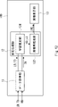
以下、実施の形態1にかかる画像処理装置100の構成及び動作について説明する。図2に、実施の形態1にかかる画像処理装置100の構成を模式的に示す。画像処理装置は、データ取得部11、推定処理部12及び画像表示部13を有する。
図3に、実施の形態1にかかる画像処理装置100の構成をより詳細に示す。図4に、実施の形態1にかかる画像処理装置100の処理のフローチャートを示す。データ取得部11は、MRI装置にて計測点を間引いて高速撮像されたk空間の生データである、k空間生データRDを読み込む。なお、以下では、MRI装置にて計測点を間引いて高速撮像された、すなわち低密度のサンプリングにより撮像されたk空間生データを低密度サンプリングk空間生データとも称する。データ取得部11は、読み込んだ低密度サンプリングk空間生データRDを、推定処理部12へ出力する。データ取得部11は、記憶装置やMRI装置から適宜低密度サンプリングk空間生データRDを読み込むことが可能である(図4のステップSE11)。
図5に、データ取得部11のk空間生データ取得の概要を示す。記憶装置としては、例えば、上述の記憶部1008やRAM1003を用いることができる。低密度サンプリングk空間生データRDは、記憶部1008及びRAM1003などの記憶装置に格納され、適宜データ取得部11が読み込むことができる。また、低密度サンプリングk空間生データRDは、MRI装置1200からデータ取得部11に与えられてもよい。
なお、データ取得部11から推定処理部12へ入力データINとしてk空間生データを与える場合、推定処理部12で行う推定処理又は後述する学習処理を円滑かつ高精度に行うには、計測点を間引いて高速撮像した低密度サンプリングk空間生データRDのままではなく、間引いた計測点を補間したk空間生データを与えることが望ましい。よって、データ取得部11は、低密度サンプリングk空間生データRDにおいて間引かれた計測点を補間する機能を有することが望ましい。
図6に、データ取得部が低密度サンプリングk空間生データRDの補間機能を有する場合の画像処理装置100の構成を模式的に示す。図7に、ステップSE11の処理手順のフローチャートを示す。図6に示すように、データ取得部11は、データ読み込み部111、画像再構成部112及び画像逆再構成部113を有する。画像再構成部112及び画像逆再構成部113は、低密度サンプリングk空間生データRDにおいて間引かれた計測点を補間するデータ補間部を構成する。
データ読み込み部111は、低密度サンプリングk空間生データRDなどのデータを読み込むものとして構成される(図7のステップSE111)。画像再構成部112は、低密度サンプリングk空間生データRDをフーリエ変換して、補間済み画像データIMG_PREを再構成する(図7のステップSE112)。画像逆再構成部113は、補間済み画像データIMG_PREを逆フーリエ変換して、補間済みk空間生データRD_PREを取得し、補間済みk空間生データRD_PREを入力データINとして推定処理部12へ出力する(図7のステップSE113)。
次いで、画像再構成部112及び画像逆再構成部113による低密度サンプリングk空間生データRDの補間について説明する。図8に、実施の形態1にかかる画像処理装置100におけるデータの流れを示す。図8で表示したk空間生データは、縦軸に位相エンコード、横軸に周波数エンコードをとっている。まず、低密度サンプリングk空間生データRDは、計測点を間引いて計測した結果であるため、所定の位相エンコードにおける計測が欠落しており、この欠落部分が黒塗り部として表されている。
この低密度サンプリングk空間生データRDをそのまま画像再構成部112で画像に再構成すると、計測点の欠落により、画質劣化を伴う低分解能の画像である補間済み画像データIMG_PREが取得される。そして、画像逆再構成部113がこの補間済み画像データIMG_PREを逆フーリエ変換すると、補間済み画像データIMG_PREの位相エンコード及び周波数エンコードの情報がk空間に展開された補間済みk空間生データRD_PREが取得される。この場合、補間済みk空間生データRD_PREには低分解能の補間済み画像データIMG_PREの位相エンコード及び周波数エンコードの情報が反映されるが、計測点の欠落がない状態のデータが得られる。このように、計測点が間引かれたk空間生データに対して画像再構成処理及び画像逆変換処理を順に行うことで、欠落した計測点を補間することができる。
サンプリング法は、一定間隔でサンプリングを飛ばすこともできるが、より効率的かつ効果的な低密度データ収集を行うため、画像情報や画像エネルギーが高い部分ほど高密度にサンプリングされ、その他の部分は低密度にサンプリングされることも行われる。低周波領域、すなわちk空間座標の中央付近は、画像エネルギーや情報が多いため高密度なサンプリングが行われ、中央から離れた高周波領域では低密度なサンプリングが行われる。
なお、ここで説明した計測点が間引かれたk空間生データの補間は例示に過ぎず、他の各種の補間方法を用いてもよいことは、言うまでもない。
推定処理部12は、推定部121及び画像再構成部122を有し、ステップSE121及びSE122を含むステップSE12の手順で処理を行う。推定部121は、予め構築された学習済みモデルを保持しており、保持している学習済みモデルに分析対象の入力データINとして低密度サンプリングk空間生データRDまたは補間済みk空間生データRD_PREを入力することで、学習結果に基づいて推定された推定k空間生データRD_ESを出力する(図4のステップSE121)。なお、ここでいう推定とは、低画質の画像に対応する入力データを学習済みモデルに入力することで、画質が回復されたデータを出力することを意味する。
画像再構成部122は、推定k空間生データRD_ESをフーリエ変換して、画質が改善された被検体の回復済み画像データIMGを再構成する。再構成された回復済み画像データIMGは、画像表示部13へ出力される(図4のステップSE122)。
なお、推定処理部12は、入力データとしてk空間生データが入力されて推定処理を行うことから、k空間推定処理部とも称する。
推定部121は、図5に示すように、外部の記憶装置などから学習済みモデルを示す情報INFを受け取り、受け取った学習済みモデルを示す情報INFに基づいて学習済みモデルを保持してもよい。情報INFは、例えば、学習済みモデルを構成するニューラルネットワークのニューロン間の重み付け係数を規定するパラメータなどの形式で与えられてもよい。
画像表示部13は、推定処理部12から受け取った回復済み画像データIMGに基づいて、診察に用いる画像をディスプレイなどの表示装置に表示する(図4のステップSE13)。画像表示部13としては、例えば、上述の出力部1007を用いてもよい。
上述では、推定処理部12において学習済みモデルを用いた推定及び画像再構成にかかる構成及び動作(すなわち、推定フェーズ)について説明したが、推定処理部12は、学習済みモデルを構築する機械学習部を更に有していてもよい。
図9に、実施の形態1にかかる画像処理装置100が学習済みモデル構築機能を有する場合の構成を模式的に示す。図10に、実施の形態1にかかる画像処理装置100の学習処理のフローチャートを示す。図9では、推定処理部12は、機械学習部123をさらに有する。
機械学習部123は、学習フェーズにおいて、記憶装置から読み込んだデータを教師有り学習によって学習するものとして構成される。学習フェーズでは、データ取得部11は、RAM1003や記憶部1008などの記憶装置に格納された、MRI装置で予め撮像された学習用データLDと教師データTDとを読み込み、機械学習部123へ出力する(図10のステップSL11)。
機械学習部123は、受け取った学習用データLD及び教師データTDをニューラルネットワークに入力して深層学習(ディープラーニング:Deep Learning)による機械学習を行う(図10のステップSL12)。学習用データLDは、予め、計測点を間引いて被検体を高速撮像することで得られた低密度サンプリングk空間生データである。教師データTDは、予め、計測点を間引くことなく、被検体を高精細撮像することで得られた高密度サンプリングk空間生データである。
本実施の形態では、画像生データの機械学習手法として、画像出力型深層学習等の画像を直接学習する手法等を使用することが望ましい。画像出力型深層学習の例としては、MTANN(Massive-Training Artificial Neural Network)が挙げられる。MTANNは、画像を出力することができる非線形深層学習モデルである。本実施の形態においては、機械学習部123は、MTANNにより取得される学習済みモデル(推定器)を学習する。
MTANNについては、特許文献4及び5にて説明されているが、以下、簡潔に説明する。MTANNは、様々なイメージ処理やパターン認識処理に適用可能なニューラルネットワークである。図11に、MTANNの構造とMTANNへのデータ入力の概要を示す。
MTANN1は、入力の画素のレベル及び出力の画素のレベルを直接的に操作可能な多層ニューラルネット(ANN:Artificial Neural Network)で構成される。MTANN1の多層ANNは、入力層2、隠れ層3及び出力層4で構成される。入力層2、隠れ層3は、複数のユニット(ニューロン)を有しているが、出力層4はユニット(ニューロン)を1つだけ有する。
入力層2、隠れ層3及び出力層4は、それぞれ、活性化関数として線形関数、シグモイド関数及び線形関数を有する。イメージ処理におけるANNの特性は出力層の活性化関数を線形関数にすることにより大幅に改善されるので、MTANNでは、出力層のユニットの活性化関数として、シグモイド関数の代わりに線形関数が適用される。
MTANN1は、ハイパスフィルタ処理、ローパスフィルタ、バンドパスフィルタ処理、ノイズ削減、エッジ強調、エッジ検出、補間、パターンマッチング、対象物強調、対象物認識、ウェーブレット変換、フーリエ変換によるテクスチャ解析及びセグメンテーションなどの各種のフィルタ処理の機能を学習により獲得し、イメージ処理及びパターン認識を行うことができる。これにより、MTANN1は、あらゆるマッピング処理を近似的に実現することが可能である。
学習フェーズ及び実行フェーズにおいてMTANNにイメージを入力するにあたり、入力イメージの画素値は、正規化される。例えば入力イメージの画素値の量子化レベルが10ビット(1024階調)で有る場合、画素値が0(ダイナミックレンジの下限値)の場合には0、ピクセル値が1023(ダイナミックレンジの上限値)の場合には1となるように、画素値が正規化される。本正規化は一例であり、他の正規化方法を行っても良い。
MTANN1へのイメージの入力は、所定の大きさを有するローカルウィンドウRSで元の入力イメージをスキャンすることで取得される、サブ領域を逐次入力することで行われる。このとき、例えば、ローカルウィンドウRSを画素の行の一端から1画素ずつシフトさせ、他端に到達したならば隣の行へシフトする処理を繰り返すことで、入力イメージをスキャンする。すなわち、ローカルウィンドウは重なりを持ちながら1画素ずつシフトする。これにより、1枚の入力データからサブ領域を切り出して、かつ、含まれる画素値を正規化した後に、MTANN1に入力することができる。
MTANN1から出力される画素値f(x,y)は、ローカルウィンドウRSの中央の画素値に対応する連続値であり、以下の式で表される。
f(x,y)=NN{I(x,y)}=NN{g(x-i,y-j) | i, j∈RS} [1]
式[1]において、x及びyは画像の座標値、NN{*}は変形ANNの出力、I(x,y)は、変形ANNへの入力ベクトル、g(x,y)はローカルウィンドウRS内の正規化された画素値である。
f(x,y)=NN{I(x,y)}=NN{g(x-i,y-j) | i, j∈RS} [1]
式[1]において、x及びyは画像の座標値、NN{*}は変形ANNの出力、I(x,y)は、変形ANNへの入力ベクトル、g(x,y)はローカルウィンドウRS内の正規化された画素値である。
出力画像の画素値f(x,y)、つまりMTANNの出力値は、適用分野に応じた所望の値の推定値として出力される。本実施の形態におけるように、低画質の画像を高画質の画像に変換する場合には、画素値f(x,y)は、高画質画像の画素値の推定値が出力される。
イメージに病変が含まれるか否かを識別する場合には、画素値f(x,y)として、「病変らしさを示す尤度」が出力される。
イメージに病変が含まれるか否かを識別する場合には、画素値f(x,y)として、「病変らしさを示す尤度」が出力される。
MTANN1は、特許文献4及び5で開示されるように、教師データを用いた教師有り学習を行うことでトレーニングされる。そして、トレーニングされたMTANNに、診断の対象となる入力イメージを入力することで、ローカルウィンドウRSごとに上述した推定画素値が得られる。そして、入力イメージから得られるローカルウィンドウの情報に基づいて、所望の出力画像を得ることが可能となる。
イメージに病変が含まれるか否かを識別する場合には、1枚の診断対象入力イメージから得られる画素値に基づいて、診断対象入力イメージに病変が含まれるか否かを判定することが可能となる。
イメージに病変が含まれるか否かを識別する場合には、1枚の診断対象入力イメージから得られる画素値に基づいて、診断対象入力イメージに病変が含まれるか否かを判定することが可能となる。
MTANNを用いる場合の学習フェーズ(すなわち学習方法)及び実行フェーズでの動作は、一般的な機械学習における手法を適用可能であり、例えば、特許文献4及び5における手法を用いることができる。つまり、MTANNで構成されたネットワークに、学習用の入力データと教師データとを入力して教師有り機械学習を行うことで、学習済みモデルを構築することができる。
なお、適用可能な深層学習手法はMTANNに限定されるものではなく、例えば、convolutional neural networks(CNN)、shift-invariant neural networks、deep belief networks(DBN)、deep neural networks(DNN)、fully convolutional neural networks(FCN)、U-Net、V-Net、multi-resolution massive-training artificial neural networks、multiple expert massive-training artificial neural networks、SegNet、VGG-16、LeNet、AlexNet、Residual network (ResNet)、Auto encoders and decoders、Generative adversarial networks(GAN)、Recurrent Neural Networks(RNN)、Recursive Neural Networks、Long Short-Term Memory(LSTM)などの各種の深層学習手法を用いることも可能である。
機械学習部123は、学習用データLDと学習用データLDに紐付けされた教師データTDとのペアを順次入力して教師有り学習によって学習することで、ニューラルネットワークのニューロン間の重み付け係数(あるいは、機械学習モデルのパラメータ)を最適化して、学習済みモデルを構築する。
機械学習部123は、推定部121へ、学習済みモデルを構築するための情報INFを推定部121に出力してもよい(図10のステップSL13)。これにより、推定部121は、受け取った情報INFに基づいて、学習済みモデルを保持することができる(図10のステップSL14)。
ここでは、推定部121と機械学習部123とを分けて説明したが、推定部の機能と機械学習部の機能とを分けることなく統合してもよい。図12に、推定部と機械学習部とを統合した場合の画像処理装置100の構成を模式的に示す。図12では、推定部121と機械学習部123とを統合した学習推定部124を設けている。この構成では、機械学習によって構築した学習済みモデルを、そのまま推定フェーズで用いることができる。
次いで、画像処理装置100が出力する画像の品質について検討する。図13に、撮像方法を変えて撮像した被検体の画像の例を示す。この図では、左側の画像は、MRI装置で通常の撮像方法で被検体を撮像して取得した高密度サンプリングk空間生データを再構成して得られた高精細画像である。中央の画像は、比較例として、通常の高精細撮像の8倍の速さで高速撮像して得られた低密度サンプリングk空間生データを再構成することで得られた高速撮像画像である。右側の画像は、中央の比較例の高速撮像により得られた低密度サンプリングk空間生データ画像を画像処理装置100にて推定処理を行うことで得られた、画質が回復された回復済み画像データIMGを表示した回復済み画像である。
中央の比較例である高速撮像画像は、過度に高速な撮像を行ったため、再構成した画像の分解能の低下、アーティファクトの増加、ノイズの増加などが生じて、左側の高精細画像と比べて組織の境界が大幅にぼやけてしまっており、特に関節の状態を読影することは困難である。よって、被検体の診断に用いる画像としては、不適切であると考え得る。
これに対し、本実施の形態にかかる画像処理装置100によって得られた、右側の回復済み画像は、中央の高速撮像画像と比べて、組織の強化がより鮮明になっている。左側の高精細画像に比べて画質は低下するものの、関節の状態を読影できる程度には鮮明な画像が得られており、高速な撮像を行いつつ診断に用いる画質の画像が得られることが理解できる。
以上、本構成によれば、計測点を間引いた高速撮像によって得られた画像情報、特にk空間生データを推定処理部に入力して推定処理を行うことで、高速撮像時よりも高精細な画像を得ることが可能である。
このように画像処理装置100によって得られた画像は、高解像度で空間分解能が高く、組織の詳細がよく描出され、ノイズ及びアーティファクトが抑制され、SN比が高く、有益な診断情報を豊富に含んでいる、高密度サンプル再構成画像であることがわかる。
また、上述したように、一般的な高速撮像手法によって診断に耐えうる画質の画像を撮像しようとすると、短縮できる撮像時間は1/2程度である。しかし、本構成によれば、例えば8倍の高速撮像によって得られたk空間生データから、診断に耐えうる画質の画像を得ることができる。よって、一般的には数十分程度であったMRI装置の撮像時間を、数分の一、例えば1/8に短縮できるため、数分程度の撮像時間で診断に耐えうる画像の取得が可能である。
したがって、一般的な高速撮像手法よりも大幅にMRI装置のスループットを向上させることができる。これにより、また、MRI装置による撮像時間を数分程度にできるので、他の検査装置、例えばCT(Computed Tomography)装置のような他の検査装置と同様のスループットを実現できる。また、撮像時間の短縮により、被検者の負担を大幅に低減することも可能である。
実施の形態2
実施の形態1では、推定処理部12に低密度サンプリングk空間生データRDを入力して得られた推定k空間生データRD_ESを再構成して画像を得る画像処理装置100について説明した。しかし、対象となるデータは、k空間生データに限られたものではなく、k空間生データから再構成して得られた画像データであってもよい。そこで、本実施の形態では、推定処理部に画像データを入力して推定処理を行う画像処理装置について説明する。
実施の形態1では、推定処理部12に低密度サンプリングk空間生データRDを入力して得られた推定k空間生データRD_ESを再構成して画像を得る画像処理装置100について説明した。しかし、対象となるデータは、k空間生データに限られたものではなく、k空間生データから再構成して得られた画像データであってもよい。そこで、本実施の形態では、推定処理部に画像データを入力して推定処理を行う画像処理装置について説明する。
図14に、実施の形態2にかかる画像処理装置200の構成を模式的に示す。図15に、実施の形態2にかかる画像処理装置200の推定フェーズにおける処理のフローチャートを示す。図16に、実施の形態2にかかる画像処理装置200におけるデータの流れを示す。画像処理装置200は、実施の形態1にかかる画像処理装置100のデータ取得部11及び推定処理部12を、それぞれデータ取得部21及び推定処理部22に置換した構成を有する。
データ取得部21は、図6の画像処理装置100のデータ取得部11から、画像逆再構成部113を除去した構成を有し、図15のステップSE21(ステップSE211及びSE212)の処理を行う。データ読み込み部111は、実施の形態1と同様に、低密度サンプリングk空間生データRDを読み込む(図15のステップSE211)。画像再構成部112は、低密度サンプリングk空間生データRDをフーリエ変換して、補間済み画像データIMG_PREを再構成し、補間済み画像データIMG_PREを入力データINとして推定処理部22へ出力する(図15のステップSE212)。データ読み込み部111及び画像再構成部112のその他の動作は、画像処理装置100と同様であるので、説明を省略する。
推定処理部22は、推定部221を少なくとも有する。推定部221は、予め構築された学習済みモデルを保持しており、保持している学習済みモデルに分析対象の入力データINとして再構成された補間済み画像データIMG_PREが入力され、推定処置を行うことで画質が回復された回復済み画像データIMGを出力する(図15のステップSE22)。
なお、推定処理部22は、入力データとして画像データが入力されて推定処理を行うことから、画像空間推定処理部とも称する。
画像表示部13は、画像処理装置100と同様に、受け取った回復済み画像データIMGに基づいて、診察に用いる画像をディスプレイなどの表示装置に表示する(図15のステップSE23)。
上述では、推定処理部22において学習済みモデルを用いた推定及び画像再構成にかかる構成及び動作(すなわち、推定フェーズ)について説明したが、推定処理部22は、学習済みモデルを構築する機械学習部を更に有していてもよい。
図17に、実施の形態2にかかる画像処理装置200が学習済みモデル構築機能を有する場合の構成を模式的に示す。図18に、実施の形態2にかかる画像処理装置200の学習処理のフローチャートを示す。図17では、推定処理部22は、機械学習部223をさらに有する。
機械学習部223は、学習フェーズにおいて、記憶装置から読み込んだデータを教師有り学習によって学習するものとして構成される。学習フェーズでは、データ取得部21は、RAM1003や記憶部1008などの記憶装置に格納された、MRI装置で予め撮像された学習用データLDと教師データTDとを読み込む。データ取得部21は、k空間画像データである学習用データLDと教師データTDを画像再構成部212によって画像データである学習用データ画像IMG_LDと教師画像データIMG_TDに再構成して、推定処理部22へ出力する(図18のステップSL21)。
機械学習部223は、学習用画像データIMG_LD及び教師画像データIMG_TDをニューラルネットワークに入力して深層学習(ディープラーニング:Deep Learning)による機械学習を行う(図18のステップSL22)。なお、本実施の形態においても。MTANNを含む各種の深層学習手法を用いて学習を行うことが可能である。
機械学習部223は、推定部221へ、学習済みモデルを構築するための情報INFを推定部221に出力してもよい(図19のステップSL23)。これにより、推定部221は、受け取った情報INFに基づいて、学習済みモデルを保持することができる(図19のステップSL24)。
また、図示しないが、実施の形態1と同様に、推定部221は外部の記憶装置などから予め用意された情報INFを受け取ってもよいし、推定部と機械学習部とを統合した学習推定部を設けて学習と推定を行ってもよい。
したがって、本構成によれば、実施の形態1と同様に、一般的な高速撮像手法よりも大幅にMRI装置のスループットを向上させることができる。これにより、また、MRI装置による撮像時間を数分程度にできるので、他の検査装置、例えばCT(Computed Tomography)装置のような他の検査装置と同様のスループットを実現できる。また、撮像時間の短縮により、被検者の負担を大幅に低減することも可能である。
実施の形態3
実施の形態1及び2では、入力データに対して推定処理を1回だけ行う例について説明した。しかし、推定処理を多段階で行うことで、最終的な出力結果である回復済み画像データIMGの画質の向上を図ることが考え得る。本実施の形態では、多段階の推定処理が可能な画像処理装置について説明する。
実施の形態1及び2では、入力データに対して推定処理を1回だけ行う例について説明した。しかし、推定処理を多段階で行うことで、最終的な出力結果である回復済み画像データIMGの画質の向上を図ることが考え得る。本実施の形態では、多段階の推定処理が可能な画像処理装置について説明する。
図19に、実施の形態3にかかる第1の構成例である画像処理装置300の構成を模式的に示す。図20に、実施の形態3にかかる第1の構成例である画像処理装置300の推定フェーズにおける処理のフローチャートを示す。画像処理装置300は、データ取得部11、k空間推定処理部32A、画像空間推定処理部32B及び画像表示部13を有する。
k空間推定処理部32Aは、画像処理装置100の推定処理部12と同様の構成を有し、図20のステップSA32(ステップSE121及びSE122)の処理を行う。k空間推定処理部32Aでは、データ取得部11からの入力データINである低密度サンプリングk空間生データRDまたは補間済みk空間生データRD_PREが推定部121に入力され、推定部121は推定k空間生データRD_ESを出力する。画像再構成部122は、推定k空間生データRD_ESを推定画像データIMG_ESに再構成して、画像空間推定処理部32Bへ出力する(図20のステップSA32)。
画像空間推定処理部32Bは、画像処理装置200の推定処理部22と同様の構成を有する。画像空間推定処理部32Bは、推定画像データIMG_ESが入力データとして入力され、推定結果である回復済み画像データIMGを画像表示部13へ出力する(図20のステップSB32)。
画像処理装置300のその後の構成及び動作は、画像処理装置100と同様であるので、説明を省略する。
以上、画像処理装置300によれば、k空間における1段階目の推定処理を行った後に、画像空間における2段階目の推定処理を行うことができる。これにより、最終的な推定結果として得られる回復済み画像データIMGの画質をより向上させることが可能となる。
なお、推定処理の順番はこの例に限られず、1段階目の推定処理として画像空間における推定処理を行った後に、2段階目の推定処理としてk空間における推定処理を行ってもよい。図21に、実施の形態3にかかる第2の構成例である画像処理装置310の構成を模式的に示す。図22に、実施の形態3にかかる第2の構成例である画像処理装置310の推定フェーズにおける処理のフローチャートを示す。画像処理装置310は、データ取得部21、画像空間推定処理部32C、k空間推定処理部32D、画像逆再構成部34及び画像表示部13を有する。
画像空間推定処理部32Cは、画像処理装置200の推定処理部22と同様の構成を有する。画像空間推定処理部32Cでは、補間済み画像データIMG_PREが入力データとして入力され、推定結果である推定中間画像データIMG_ES0を画像逆再構成部34へ出力する(図22のステップSC32)。
画像逆再構成部34は、推定中間画像データIMG_ES0をフーリエ変換して中間k空間生データRD_ES0を取得し、中間k空間生データRD_ES0をk空間推定処理部32Dへ出力する(図22のステップS34)。
k空間推定処理部32Dは、画像処理装置100の推定処理部12と同様の構成を有し、図22のステップSD32(ステッIMG_ES0プSE121及びSE122)の処理を行う。k空間推定処理部32Dでは、中間k空間生データRD_ES0が推定部121に入力され、推定部121は推定結果である推定k空間生データRD_ESを出力する。画像再構成部122は、推定k空間生データRD_ESを回復済み画像データIMGに再構成して、画像表示部13へ出力する(図22のステップSD32)。
画像処理装置310のその後の構成及び動作は、画像処理装置200と同様であるので、説明を省略する。
以上、画像処理装置310によれば、画像空間における1段階目の推定処理を行った後に、k空間における2段階目の推定処理を行うことができる。これにより、最終的な推定結果として得られる回復済み画像データIMGの画質をより向上させることが可能となる。
なお、2段階の推定処理は、繰り返し行うことがある。例えば、k空間推定処理部32A及び画像空間推定処理部32Bからなる繰り返し推定処理部301を、データ取得部11と画像表示部13との間に、2個以上直列的に配列してもよい。これにより、画像処理装置300が行う2段階の推定処理を複数回繰り返して行うことも可能である。この場合、繰り返し推定処理部301のそれぞれにk空間生データを入力するために、隣接する2つの繰り返し推定処理部301の間に、画像逆再構成部34と同様の画像逆再構成部を挿入すればよい。
画像空間推定処理部32C、k空間推定処理部32D及び画像逆再構成部34からなる繰り返し推定処理部311を、データ取得部21と画像表示部13との間に、2個以上直列的に配列してもよい。
また、繰り返し推定処理部301と繰り返し推定処理部311とを、交互に又はランダムに直列的に配列してもよい。繰り返し推定処理部301又は311の後に繰り返し推定処理部301を配置する場合、後段の繰り返し推定処理部301にk空間生データを入力するために、前段の繰り返し推定処理部301又は311と後段の繰り返し推定処理部301との間に、画像逆再構成部34と同様の画像逆再構成部を挿入すればよい。なお、先頭の繰り返し推定処理部が繰り返し推定処理部301である場合にはデータ取得部11によって入力データを入力し、先頭の繰り返し推定処理部が繰り返し推定処理部311である場合にはデータ取得部21によって入力データを入力すればよい。
以上、本実施の形態にかかる画像処理装置によれば、推定処理を複数回行うことで、最終的に得られる画像データの画質をより向上させることができる。
実施の形態4
実施の形態3では、入力データに対して偶数回数の推定処理を行う例について説明した。しかし、推定処理については3回以上の奇数回だけ行ってもよい。本実施の形態では、3回以上の奇数回の推定処理が可能な画像処理装置について説明する。
実施の形態3では、入力データに対して偶数回数の推定処理を行う例について説明した。しかし、推定処理については3回以上の奇数回だけ行ってもよい。本実施の形態では、3回以上の奇数回の推定処理が可能な画像処理装置について説明する。
図23に、実施の形態4にかかる第1の構成例である画像処理装置400の構成を模式的に示す。図24に、実施の形態4にかかる第1の構成例である画像処理装置400の推定フェーズにおける処理のフローチャートを示す。画像処理装置400は、実施の形態3にかかる画像処理装置300に、画像逆再構成部44及びk空間推定処理部42Aを追加した構成を有する。
本構成では、k空間推定処理部32Aは、推定結果として推定画像データIMG_ES1を出力する。画像空間推定処理部32Bは、入力データである推定画像データIMG_ES1に応じた推定結果として、推定画像データIMG_ES2を画像逆再構成部44へ出力する。
画像逆再構成部44は、推定画像データIMG_ES2を逆フーリエ変換してk空間生データRD_ES2を取得し、推定k空間生データRD_ES2をk空間推定処理部42Aへ出力する(図24のステップS44)。
k空間推定処理部42Aは、画像処理装置100の推定処理部12と同様の構成を有し、図24のステップSA42(ステップSE121及びSE122)の処理を行う。k空間推定処理部42Aの推定部121は推定k空間生データRD_ES2に応じた推定結果であるk空間生データRD_ES3を出力する。画像再構成部122は、推定k空間生データRD_ES3を再構成して、最終推定結果である回復済み画像データIMGを画像表示部13へ出力する(図22のステップSA42)。
画像処理装置400のその後の構成及び動作は、画像処理装置300と同様であるので、説明を省略する。
以上、画像処理装置400によれば、k空間における1段階目の推定処理、画像空間における2段階目の推定処理、k空間における3段階目の推定処理を行って最終的な推定結果である回復済み画像データIMGを得ることができる。よって、多段階の推定処理によって回復済み画像データIMGの画質をより向上させることが可能となる。
なお、k空間における推定処理及び画像空間における推定処理の順番は、入れ替えてもよい。図25に、実施の形態4にかかる第2の構成例である画像処理装置410の構成を模式的に示す。図26に、実施の形態4にかかる第2の構成例である画像処理装置410の推定フェーズにおける処理のフローチャートを示す。画像処理装置410は、実施の形態3にかかる画像処理装置310に、画像空間推定処理部42Bを追加した構成を有する。
本構成では、k空間推定処理部32Dは、推定画像データIMG_ES3を画像空間推定処理部42Bへ出力する。
画像空間推定処理部42Bは、画像処理装置200の推定処理部22と同様の構成を有する。画像空間推定処理部42Bは、推定画像データIMG_ES3に応じた推定結果である回復済み画像データIMGを画像表示部13へ出力する(図26のステップSB42)。
画像処理装置410のその後の構成及び動作は、画像処理装置310と同様であるので、説明を省略する。
なお、実施の形態3と同様に、2段階の推定処理は、繰り返し行うことがある。例えば、k空間推定処理部32A、画像空間推定処理部32B及びk空間推定処理部42Aからなる繰り返し推定処理部401を、データ取得部11と画像表示部13との間に、2個以上直列的に配列してもよい。これにより、画像処理装置400が行う3段階の推定処理を複数回繰り返して行うことも可能である。この場合、繰り返し推定処理部401のそれぞれにk空間生データを入力するために、隣接する2つの繰り返し推定処理部401の間に、画像逆再構成部44と同様の画像逆再構成部を挿入すればよい。
画像空間推定処理部32C、k空間推定処理部32D及び画像空間推定処理部42Bからなる繰り返し推定処理部411を、データ取得部21と画像表示部13との間に、2個以上直列的に配列してもよい。
また、繰り返し推定処理部401と繰り返し推定処理部411とを、交互に又はランダムに直列的に配列してもよい。繰り返し推定処理部401又は411の後に繰り返し推定処理部401を配置する場合、後段の繰り返し推定処理部401にk空間生データを入力するために、前段の繰り返し推定処理部401又は411と後段の繰り返し推定処理部401との間に、画像逆再構成部44と同様の画像逆再構成部を挿入すればよい。なお、先頭の繰り返し推定処理部が繰り返し推定処理部401である場合にはデータ取得部11によって入力データを入力し、先頭の繰り返し推定処理部が繰り返し推定処理部411である場合にはデータ取得部21によって入力データを入力すればよい。
以上、本実施の形態にかかる画像処理装置によれば、推定処理を複数回行うことで、実施の形態3と同様に、最終的に得られる画像データの画質をより向上させることができる。
その他の実施の形態
なお、本発明は上記実施の形態に限られたものではなく、趣旨を逸脱しない範囲で適宜変更することが可能である。例えば、実施の形態3にかかる繰り返し推定処理部301及び311と、実施の形態4にかかる繰り返し推定処理部401及び411とを、交互に又はランダムに配列してもよい。この場合、繰り返し推定処理部301、311、311又は411の後に繰り返し推定処理部301又は401を配置する場合、前段に配置される繰り返し推定処理部(繰り返し推定処理部301、311、301又は401)と後段に配置される繰り返し推定処理部(繰り返し推定処理部311又は411)との間に、画像逆再構成部34又は44と同様の画像逆再構成部を挿入すればよい。なお、先頭の繰り返し推定処理部が繰り返し推定処理部301又は401である場合にはデータ取得部11によって入力データを入力し、先頭の繰り返し推定処理部が繰り返し推定処理部311又は411である場合にはデータ取得部21によって入力データを入力すればよい。
なお、本発明は上記実施の形態に限られたものではなく、趣旨を逸脱しない範囲で適宜変更することが可能である。例えば、実施の形態3にかかる繰り返し推定処理部301及び311と、実施の形態4にかかる繰り返し推定処理部401及び411とを、交互に又はランダムに配列してもよい。この場合、繰り返し推定処理部301、311、311又は411の後に繰り返し推定処理部301又は401を配置する場合、前段に配置される繰り返し推定処理部(繰り返し推定処理部301、311、301又は401)と後段に配置される繰り返し推定処理部(繰り返し推定処理部311又は411)との間に、画像逆再構成部34又は44と同様の画像逆再構成部を挿入すればよい。なお、先頭の繰り返し推定処理部が繰り返し推定処理部301又は401である場合にはデータ取得部11によって入力データを入力し、先頭の繰り返し推定処理部が繰り返し推定処理部311又は411である場合にはデータ取得部21によって入力データを入力すればよい。
実施の形態3及び4で説明した繰り返し処理は、以下のように解釈することが可能である。すなわち、推定処理部として、1つ以上のk空間推定処理部と1つ以上の画像空間推定処理部とが直列的に配列されたものを用いてもよい。この場合、k空間推定処理部又は画像空間推定処理部の後段にk空間推定処理部が配置される場合には、前段のk空間推定処理部又は画像空間推定処理部と後段のk空間推定処理部との間に画像逆再構成部を設け、前段のk空間推定処理部又は画像空間推定処理部が出力する画像データを逆フーリエ変換して逆再構成したk空間生データを後段のk空間推定処理部へ出力すればよい。また、k空間推定処理部及び画像空間推定処理部の直列的な配列の先頭がk空間推定処理部である場合には、データ取得部は、低密度サンプリングk空間生データの間引かれた計測点を補間した補間済みk空間生データに変換し、補間済みk空間生データを前記入力データとして、先頭のk空間推定処理部へ出力すればよい。k空間推定処理部及び画像空間推定処理部の直列的な配列の先頭が画像空間推定処理部である場合には、データ取得部は、低密度サンプリングk空間生データをフーリエ変換した補間済み画像データを入力データとして先頭の画像空間推定処理部へ出力すればよい。
上述の推定処理部は、k空間生データを入力データとする複数の処理ラインを並列配置したフィルターバンク画像出力型の推定処理部として構成されてもよい。図27に、フィルターバンク画像出力型の推定処理部50の構成を模式的に示す。推定処理部50は、ローパスフィルタ(LPF)51、バンドパスフィルタ(BPF)52、ハイパスフィルタ(HPF)53、学習推定部54~56、結合層57を有する。
入力データINは、補間済みのk空間生データであり、LPF51、BPF52及びHPF53に入力される。LPF51は入力データINの低周波数帯域IN_Lを学習推定部54へ通過させ、BPF52は入力データINの中周波数帯域IN_Mを学習推定部55へ通過させ、HPF53は入力データINの高周波数帯域IN_Hを学習推定部56へ通過させる。k空間は既に周波数空間であるため、これらの周波数帯域限定処理はk空間画像と限定する帯域を1、その他を0とする2次元又は3次元関数との乗算により実現可能である。
学習推定部54~56は、それぞれ入力された入力データINの周波数成分を用いて推定処理及び学習処理の一方又は両方を行うことができる。学習推定部54~56が出力する処理後のk空間生データOUT1~OUT3は、を結合層57へ出力される。結合層57は、k空間生データOUT1~OUT3を結合することで、全周波数領域に対応するk空間生データRD_OUTを出力することができる。これにより、分割された周波数帯域に特化した処理を行う学習推定部(推定部又は学習部であってもよいことは、言うまでもない。)で処理を行うことで、より高精度なk空間生データを出力することが可能となる。
上述の実施の形態では、本発明を主にハードウェアの構成として説明したが、これに限定されるものではなく、任意の処理を、CPU(Central Processing Unit)にコンピュータプログラムを実行させることにより実現することも可能である。この場合、コンピュータプログラムは、様々なタイプの非一時的なコンピュータ可読媒体(non-transitory computer readable medium)を用いて格納され、コンピュータに供給することができる。非一時的なコンピュータ可読媒体は、様々なタイプの実体のある記録媒体(tangible storage medium)を含む。非一時的なコンピュータ可読媒体の例は、磁気記録媒体(例えばフレキシブルディスク、磁気テープ、ハードディスクドライブ)、光磁気記録媒体(例えば光磁気ディスク)、CD-ROM(Read Only Memory)、CD-R、CD-R/W、半導体メモリ(例えば、マスクROM、PROM(Programmable ROM)、EPROM(Erasable PROM)、フラッシュROM、RAM(random access memory))を含む。また、プログラムは、様々なタイプの一時的なコンピュータ可読媒体(transitory computer readable medium)によってコンピュータに供給されてもよい。一時的なコンピュータ可読媒体の例は、電気信号、光信号、及び電磁波を含む。一時的なコンピュータ可読媒体は、電線及び光ファイバ等の有線通信路、又は無線通信路を介して、プログラムをコンピュータに供給できる。
以上、実施の形態を参照して本願発明を説明したが、本願発明は上記によって限定されるものではない。本願発明の構成や詳細には、発明のスコープ内で当業者が理解し得る様々な変更をすることができる。
この出願は、2021年3月2日に出願された日本出願特願2021-32652を基礎とする優先権を主張し、その開示の全てをここに取り込む。
1 MTANN
2 入力層
3 隠れ層
4 出力層
11、21 データ取得部
12、22、50 推定処理部
13 画像表示部
32A、32D、42A k空間推定処理部
32B、32C、42B 画像空間推定処理部
34、44、113 画像逆再構成部
51 LPF
52 BPF
53 HPF
54~56、124 学習推定部
57 結合層
100、200、300、310、400、410 画像処理装置
111 データ読み込み部
112、122 画像再構成部
121、221 推定部
123、223 機械学習部
301、311、401、411 繰り返し推定処理部
1000 コンピュータ
1001 CPU
1002 ROM
1003 RAM
1004 バス
1005 入出力インターフェイス
1006 入力部
1007 出力部
1008 記憶部
1009 通信部
1010 ドライブ
1011 磁気ディスク
1012 光ディスク
1013 フレキシブルディスク
1014 半導体メモリ
IMG_ES、IMG_ES1~IMG_ES3 推定画像データ
IMG_ES0 推定中間画像データ
IMG_PRE 補間済み画像データ
IMG_LD、LD 学習用画像データ
IMG_TD、TD 教師画像データ
IN 入力データ
INF 情報
LD 学習用データ
RD 低密度サンプリングk空間生データ
RD_ES、RD_ES2、RD_ES3、 推定k空間生データ
RD_ES0 中間k空間生データ
RD_PRE 補間済みk空間生データ
2 入力層
3 隠れ層
4 出力層
11、21 データ取得部
12、22、50 推定処理部
13 画像表示部
32A、32D、42A k空間推定処理部
32B、32C、42B 画像空間推定処理部
34、44、113 画像逆再構成部
51 LPF
52 BPF
53 HPF
54~56、124 学習推定部
57 結合層
100、200、300、310、400、410 画像処理装置
111 データ読み込み部
112、122 画像再構成部
121、221 推定部
123、223 機械学習部
301、311、401、411 繰り返し推定処理部
1000 コンピュータ
1001 CPU
1002 ROM
1003 RAM
1004 バス
1005 入出力インターフェイス
1006 入力部
1007 出力部
1008 記憶部
1009 通信部
1010 ドライブ
1011 磁気ディスク
1012 光ディスク
1013 フレキシブルディスク
1014 半導体メモリ
IMG_ES、IMG_ES1~IMG_ES3 推定画像データ
IMG_ES0 推定中間画像データ
IMG_PRE 補間済み画像データ
IMG_LD、LD 学習用画像データ
IMG_TD、TD 教師画像データ
IN 入力データ
INF 情報
LD 学習用データ
RD 低密度サンプリングk空間生データ
RD_ES、RD_ES2、RD_ES3、 推定k空間生データ
RD_ES0 中間k空間生データ
RD_PRE 補間済みk空間生データ
Claims (11)
- MRI装置にて計測点を間引いて被検体を撮像することで得られた低密度サンプリングk空間生データを取得し、前記低密度サンプリングk空間生データに基づく入力データを出力するデータ取得部と、
前記入力データを学習済みモデルに入力することで推定処理を行い、間引かれた計測点により低下した画質が回復された回復済み画像データを出力する推定処理部と、
前記回復済み画像データを表示する画像表示部と、を備える、
画像処理装置。 - 前記データ取得部は、前記低密度サンプリングk空間生データの間引かれた計測点を補間した補間済みk空間生データに変換し、前記補間済みk空間生データを前記入力データとして前記推定処理部へ出力し、
前記推定処理部は、前記補間済みk空間生データを前記学習済みモデルに入力することで推定処理を行い、前記間引かれた計測点により低下した画質が回復された推定k空間生データを出力し、前記推定k空間生データをフーリエ変換することで再構成した前記回復済み画像データを出力するk空間推定処理部として構成される、
請求項1に記載の画像処理装置。 - 前記データ取得部は、前記低密度サンプリングk空間生データをフーリエ変換することで再構成した画像データを逆フーリエ変換して逆再構成することで、前記補間済みk空間生データを取得する、
請求項2に記載の画像処理装置。 - 前記データ取得部は、前記低密度サンプリングk空間生データをフーリエ変換した画像データを前記入力データとして前記推定処理部へ出力し、
前記推定処理部は、変換された前記画像データを前記学習済みモデルに入力することで推定処理を行い、前記間引かれた計測点により低下した画質が回復された前記回復済み画像データ出力する画像空間推定処理部として構成される、
請求項1に記載の画像処理装置。 - 前記推定処理部は、1つ以上のk空間推定処理部と1つ以上の画像空間推定処理部と、が直列的に配列され、
前記k空間推定処理部は、入力データであるk空間生データを前記学習済みモデルに入力することで推定処理を行い、画質が回復されたk空間生データを出力し、前記k空間生データをフーリエ変換することで再構成した第2の画像データを出力し、
前記画像空間推定処理部は、入力データである画像データを前記学習済みモデルに入力することで推定処理を行い、画質が回復された画像データを出力し、
前記画像空間推定処理部の後段に前記k空間推定処理部が配置される場合には、前記画像空間推定処理部と前記k空間推定処理部との間に、前段の前記画像空間推定処理部が出力する画像データを逆フーリエ変換して逆再構成したk空間生データを、後段の前記k空間推定処理部へ出力する画像逆再構成部が設けられ、
前記k空間推定処理部及び前記画像空間推定処理部の直列的な配列の最後尾から出力される画像データが前記回復済み画像データとして出力される、
請求項1に記載の画像処理装置。 - 前記k空間推定処理部及び前記画像空間推定処理部の直列的な配列の先頭が前記k空間推定処理部である場合には、前記データ取得部は、前記低密度サンプリングk空間生データの間引かれた計測点を補間した補間済みk空間生データに変換し、前記補間済みk空間生データを前記入力データとして、先頭の前記k空間推定処理部へ出力し、
前記k空間推定処理部及び前記画像空間推定処理部の直列的な配列の先頭が前記画像空間推定処理部である場合には、前記データ取得部は、前記低密度サンプリングk空間生データをフーリエ変換した画像データを前記入力データとして先頭の前記画像空間推定処理部へ出力する、
請求項5に記載の画像処理装置。 - 前記データ取得部は、前記MRI装置にて計測点を間引いて前記被検体を撮像することで予め得られた低密度サンプリングk空間生データである学習データと、前記MRI装置にて計測点を間引くことなく前記被検体を撮像することで予め得られた高密度サンプリングk空間生データである教師データとを読み込み、読み込んだ前記学習データ及び前記教師データに基づく学習用入力データを前記推定処理部へ出力し、
前記推定処理部は、前記学習用入力データに基づいた教師有り学習を行うことで、前記学習済みモデルを構築する、
請求項1乃至6のいずれか一項に記載の画像処理装置。 - 前記データ取得部は、前記MRI装置にて計測点を間引いて前記被検体を撮像することで予め得られた低密度サンプリングk空間生データを再構成して得られた学習データと、前記MRI装置にて計測点を間引くことなく前記被検体を撮像することで予め得られた高密度サンプリングk空間生データを再構成して得られた教師データと、を読み込み、読み込んだ前記学習データ及び前記教師データに基づく学習用入力データを前記推定処理部へ出力し、
前記推定処理部は、前記学習用入力データに基づいた教師有り学習を行うことで、前記学習済みモデルを構築する、
請求項1乃至6のいずれか一項に記載の画像処理装置。 - 前記学習済みモデルは、MTANN(Massive-Training Artificial Neural Network)として構成されたネットワークに学習用データと教師データとを入力して学習を行うことで構築されたネットワークである、
請求項1乃至8のいずれか一項に記載の画像処理装置。 - MRI装置にて計測点を間引いて被検体を撮像することで得られた低密度サンプリングk空間生データを取得し、前記低密度サンプリングk空間生データに基づく入力データを出力し、
前記入力データを学習済みモデルに入力することで推定処理を行い、間引かれた計測点により低下した画質が回復された回復済み画像データを出力し、
前記回復済み画像データを表示する、
画像処理方法。 - MRI装置にて計測点を間引いて被検体を撮像することで得られた低密度サンプリングk空間生データを取得し、前記低密度サンプリングk空間生データに基づく入力データを出力する処理と、
前記入力データを学習済みモデルに入力することで推定処理を行い、間引かれた計測点により低下した画質が回復された回復済み画像データを出力する処理と、
前記回復済み画像データを表示する処理と、をコンピュータに実行させる、
プログラムが格納された非一時的なコンピュータ可読媒体。
Priority Applications (2)
| Application Number | Priority Date | Filing Date | Title |
|---|---|---|---|
| JP2023503899A JPWO2022186263A5 (ja) | 2022-03-02 | 画像処理装置、画像処理方法及びプログラム | |
| US18/546,940 US20240257413A1 (en) | 2021-03-02 | 2022-03-02 | Image processing apparatus, image processing method, and non-transitory computer-readable medium storing program |
Applications Claiming Priority (2)
| Application Number | Priority Date | Filing Date | Title |
|---|---|---|---|
| JP2021-032652 | 2021-03-02 | ||
| JP2021032652 | 2021-03-02 |
Publications (1)
| Publication Number | Publication Date |
|---|---|
| WO2022186263A1 true WO2022186263A1 (ja) | 2022-09-09 |
Family
ID=83154620
Family Applications (1)
| Application Number | Title | Priority Date | Filing Date |
|---|---|---|---|
| PCT/JP2022/008813 Ceased WO2022186263A1 (ja) | 2021-03-02 | 2022-03-02 | 画像処理装置、画像処理方法及びプログラムが格納された非一時的なコンピュータ可読媒体 |
Country Status (2)
| Country | Link |
|---|---|
| US (1) | US20240257413A1 (ja) |
| WO (1) | WO2022186263A1 (ja) |
Family Cites Families (4)
| Publication number | Priority date | Publication date | Assignee | Title |
|---|---|---|---|---|
| US6819790B2 (en) * | 2002-04-12 | 2004-11-16 | The University Of Chicago | Massive training artificial neural network (MTANN) for detecting abnormalities in medical images |
| JP5984258B2 (ja) * | 2012-04-27 | 2016-09-06 | 東芝メディカルシステムズ株式会社 | 磁気共鳴イメージング装置及び画像処理装置 |
| US11412948B2 (en) * | 2016-05-13 | 2022-08-16 | University Of Southern California | Method for improved dynamic contrast enhanced imaging using tracer-kinetic models as constraints |
| JP7185491B2 (ja) * | 2018-11-02 | 2022-12-07 | 富士フイルムヘルスケア株式会社 | 磁気共鳴イメージング装置およびその制御方法 |
-
2022
- 2022-03-02 WO PCT/JP2022/008813 patent/WO2022186263A1/ja not_active Ceased
- 2022-03-02 US US18/546,940 patent/US20240257413A1/en active Pending
Non-Patent Citations (1)
| Title |
|---|
| RAVISHANKAR SAIPRASAD; YE JONG CHUL; FESSLER JEFFREY A.: "Image Reconstruction: From Sparsity to Data-Adaptive Methods and Machine Learning", PROCEEDINGS OF THE IEEE, IEEE. NEW YORK., US, vol. 108, no. 1, 1 January 2020 (2020-01-01), US , pages 86 - 109, XP011763168, ISSN: 0018-9219, DOI: 10.1109/JPROC.2019.2936204 * |
Also Published As
| Publication number | Publication date |
|---|---|
| JPWO2022186263A1 (ja) | 2022-09-09 |
| US20240257413A1 (en) | 2024-08-01 |
Similar Documents
| Publication | Publication Date | Title |
|---|---|---|
| CN110461228B (zh) | 使用多对比度和深度学习改进医学图像的质量 | |
| Lyu et al. | Super-resolution MRI through deep learning | |
| CN113160380B (zh) | 三维磁共振影像超分辨重建方法、电子设备和存储介质 | |
| CN113298710B (zh) | 基于外部注意力机制的光学相干层析超分辨率成像方法 | |
| CN110490832A (zh) | 一种基于正则化深度图像先验方法的磁共振图像重建方法 | |
| CN108090871A (zh) | 一种基于卷积神经网络的多对比度磁共振图像重建方法 | |
| CN115294229A (zh) | 用于重建磁共振成像(mri)图像的方法及设备 | |
| US12521033B2 (en) | Method and system for low-field MRI denoising with a deep complex-valued convolutional neural network | |
| CN111353935A (zh) | 基于深度学习的磁共振成像优化方法及其设备 | |
| US12607695B2 (en) | Time compressed dynamic MR deep learning reconstruction | |
| CN119672141B (zh) | 一种基于多级小波卷积网络的快速磁共振重建方法及系统 | |
| CN111681297B (zh) | 图像重建方法、计算机设备和存储介质 | |
| US20250321307A1 (en) | Magnetic resonance image reconstruction device and magnetic resonance image reconstruction method | |
| CN114241077A (zh) | 一种ct图像分辨率优化方法及装置 | |
| CN114972570A (zh) | 图像重建方法及设备 | |
| CN112037304A (zh) | 基于swi相位图像的两阶段的边缘增强qsm重建方法 | |
| CN119205527A (zh) | 一种基于深度学习的跨数据集磁共振多模态超分辨图像的合成方法 | |
| CN116385284A (zh) | 一种三维磁共振图像的图像增强系统 | |
| CN116416327A (zh) | 医学图像处理方法、装置、设备及存储介质 | |
| CN120411291A (zh) | 一种基于双频细化扩散先验的无监督稀疏ct图像重建方法 | |
| CN117333571B (zh) | 磁共振图像的重建方法、系统、设备及介质 | |
| US20240257413A1 (en) | Image processing apparatus, image processing method, and non-transitory computer-readable medium storing program | |
| CN118279158A (zh) | 一种磁共振脑影像的质量提升方法、装置及计算机设备 | |
| Hussain et al. | Revolutionizing MRI Reconstruction from Compressed Sensing k-space measurements: An AI-Driven Feature Extraction Approach | |
| Mhatre et al. | Deepfusion: A novel deep learning technique for enhanced image super-resolution |
Legal Events
| Date | Code | Title | Description |
|---|---|---|---|
| 121 | Ep: the epo has been informed by wipo that ep was designated in this application |
Ref document number: 22763317 Country of ref document: EP Kind code of ref document: A1 |
|
| WWE | Wipo information: entry into national phase |
Ref document number: 2023503899 Country of ref document: JP |
|
| NENP | Non-entry into the national phase |
Ref country code: DE |
|
| 122 | Ep: pct application non-entry in european phase |
Ref document number: 22763317 Country of ref document: EP Kind code of ref document: A1 |