WO2022185614A1 - インバータ、並列インバータシステム、及び、インバータの制御方法 - Google Patents
インバータ、並列インバータシステム、及び、インバータの制御方法 Download PDFInfo
- Publication number
- WO2022185614A1 WO2022185614A1 PCT/JP2021/040360 JP2021040360W WO2022185614A1 WO 2022185614 A1 WO2022185614 A1 WO 2022185614A1 JP 2021040360 W JP2021040360 W JP 2021040360W WO 2022185614 A1 WO2022185614 A1 WO 2022185614A1
- Authority
- WO
- WIPO (PCT)
- Prior art keywords
- inverter
- frequency
- power
- voltage
- value
- Prior art date
- Legal status (The legal status is an assumption and is not a legal conclusion. Google has not performed a legal analysis and makes no representation as to the accuracy of the status listed.)
- Ceased
Links
Images


Classifications
-
- H—ELECTRICITY
- H02—GENERATION; CONVERSION OR DISTRIBUTION OF ELECTRIC POWER
- H02M—APPARATUS FOR CONVERSION BETWEEN AC AND AC, BETWEEN AC AND DC, OR BETWEEN DC AND DC, AND FOR USE WITH MAINS OR SIMILAR POWER SUPPLY SYSTEMS; CONVERSION OF DC OR AC INPUT POWER INTO SURGE OUTPUT POWER; CONTROL OR REGULATION THEREOF
- H02M7/00—Conversion of AC power input into DC power output; Conversion of DC power input into AC power output
- H02M7/42—Conversion of DC power input into AC power output without possibility of reversal
- H02M7/44—Conversion of DC power input into AC power output without possibility of reversal by static converters
- H02M7/48—Conversion of DC power input into AC power output without possibility of reversal by static converters using discharge tubes with control electrode or semiconductor devices with control electrode
- H02M7/493—Conversion of DC power input into AC power output without possibility of reversal by static converters using discharge tubes with control electrode or semiconductor devices with control electrode the static converters being arranged for operation in parallel
-
- H—ELECTRICITY
- H02—GENERATION; CONVERSION OR DISTRIBUTION OF ELECTRIC POWER
- H02J—ELECTRIC POWER NETWORKS; CIRCUIT ARRANGEMENTS OR SYSTEMS FOR SUPPLYING OR DISTRIBUTING ELECTRIC POWER; SYSTEMS FOR STORING ELECTRIC ENERGY
- H02J3/00—Circuit arrangements for AC mains or AC distribution networks
- H02J3/001—Arrangements for handling faults or abnormalities, e.g. emergencies or contingencies
- H02J3/0014—Arrangements for handling faults or abnormalities, e.g. emergencies or contingencies for preventing or reducing power oscillations in networks
- H02J3/00142—Oscillations concerning frequency
-
- H—ELECTRICITY
- H02—GENERATION; CONVERSION OR DISTRIBUTION OF ELECTRIC POWER
- H02J—ELECTRIC POWER NETWORKS; CIRCUIT ARRANGEMENTS OR SYSTEMS FOR SUPPLYING OR DISTRIBUTING ELECTRIC POWER; SYSTEMS FOR STORING ELECTRIC ENERGY
- H02J3/00—Circuit arrangements for AC mains or AC distribution networks
- H02J3/38—Arrangements for feeding a single network from two or more generators or sources in parallel; Arrangements for feeding already energised networks from additional generators or sources in parallel
- H02J3/40—Synchronisation of generators for connection to a network or to another generator
-
- H—ELECTRICITY
- H02—GENERATION; CONVERSION OR DISTRIBUTION OF ELECTRIC POWER
- H02M—APPARATUS FOR CONVERSION BETWEEN AC AND AC, BETWEEN AC AND DC, OR BETWEEN DC AND DC, AND FOR USE WITH MAINS OR SIMILAR POWER SUPPLY SYSTEMS; CONVERSION OF DC OR AC INPUT POWER INTO SURGE OUTPUT POWER; CONTROL OR REGULATION THEREOF
- H02M1/00—Details of apparatus for conversion
- H02M1/0003—Details of control, feedback or regulation circuits
- H02M1/0025—Arrangements for modifying reference values, feedback values or error values in the control loop of a converter
-
- H—ELECTRICITY
- H02—GENERATION; CONVERSION OR DISTRIBUTION OF ELECTRIC POWER
- H02J—ELECTRIC POWER NETWORKS; CIRCUIT ARRANGEMENTS OR SYSTEMS FOR SUPPLYING OR DISTRIBUTING ELECTRIC POWER; SYSTEMS FOR STORING ELECTRIC ENERGY
- H02J2101/00—Supply or distribution of decentralised, dispersed or local electric power generation
- H02J2101/20—Dispersed power generation using renewable energy sources
- H02J2101/22—Solar energy
- H02J2101/24—Photovoltaics
-
- H—ELECTRICITY
- H02—GENERATION; CONVERSION OR DISTRIBUTION OF ELECTRIC POWER
- H02J—ELECTRIC POWER NETWORKS; CIRCUIT ARRANGEMENTS OR SYSTEMS FOR SUPPLYING OR DISTRIBUTING ELECTRIC POWER; SYSTEMS FOR STORING ELECTRIC ENERGY
- H02J3/00—Circuit arrangements for AC mains or AC distribution networks
- H02J3/38—Arrangements for feeding a single network from two or more generators or sources in parallel; Arrangements for feeding already energised networks from additional generators or sources in parallel
- H02J3/381—Dispersed generators
-
- H—ELECTRICITY
- H02—GENERATION; CONVERSION OR DISTRIBUTION OF ELECTRIC POWER
- H02J—ELECTRIC POWER NETWORKS; CIRCUIT ARRANGEMENTS OR SYSTEMS FOR SUPPLYING OR DISTRIBUTING ELECTRIC POWER; SYSTEMS FOR STORING ELECTRIC ENERGY
- H02J3/00—Circuit arrangements for AC mains or AC distribution networks
- H02J3/38—Arrangements for feeding a single network from two or more generators or sources in parallel; Arrangements for feeding already energised networks from additional generators or sources in parallel
- H02J3/46—Controlling the sharing of generated power between the generators, sources or networks
-
- H—ELECTRICITY
- H02—GENERATION; CONVERSION OR DISTRIBUTION OF ELECTRIC POWER
- H02M—APPARATUS FOR CONVERSION BETWEEN AC AND AC, BETWEEN AC AND DC, OR BETWEEN DC AND DC, AND FOR USE WITH MAINS OR SIMILAR POWER SUPPLY SYSTEMS; CONVERSION OF DC OR AC INPUT POWER INTO SURGE OUTPUT POWER; CONTROL OR REGULATION THEREOF
- H02M7/00—Conversion of AC power input into DC power output; Conversion of DC power input into AC power output
- H02M7/42—Conversion of DC power input into AC power output without possibility of reversal
- H02M7/44—Conversion of DC power input into AC power output without possibility of reversal by static converters
- H02M7/48—Conversion of DC power input into AC power output without possibility of reversal by static converters using discharge tubes with control electrode or semiconductor devices with control electrode
- H02M7/53—Conversion of DC power input into AC power output without possibility of reversal by static converters using discharge tubes with control electrode or semiconductor devices with control electrode using devices of a triode or transistor type requiring continuous application of a control signal
- H02M7/537—Conversion of DC power input into AC power output without possibility of reversal by static converters using discharge tubes with control electrode or semiconductor devices with control electrode using devices of a triode or transistor type requiring continuous application of a control signal using semiconductor devices only, e.g. single switched pulse inverters
- H02M7/539—Conversion of DC power input into AC power output without possibility of reversal by static converters using discharge tubes with control electrode or semiconductor devices with control electrode using devices of a triode or transistor type requiring continuous application of a control signal using semiconductor devices only, e.g. single switched pulse inverters with automatic control of output wave form or frequency
-
- Y—GENERAL TAGGING OF NEW TECHNOLOGICAL DEVELOPMENTS; GENERAL TAGGING OF CROSS-SECTIONAL TECHNOLOGIES SPANNING OVER SEVERAL SECTIONS OF THE IPC; TECHNICAL SUBJECTS COVERED BY FORMER USPC CROSS-REFERENCE ART COLLECTIONS [XRACs] AND DIGESTS
- Y02—TECHNOLOGIES OR APPLICATIONS FOR MITIGATION OR ADAPTATION AGAINST CLIMATE CHANGE
- Y02E—REDUCTION OF GREENHOUSE GAS [GHG] EMISSIONS, RELATED TO ENERGY GENERATION, TRANSMISSION OR DISTRIBUTION
- Y02E10/00—Energy generation through renewable energy sources
- Y02E10/50—Photovoltaic [PV] energy
- Y02E10/56—Power conversion systems, e.g. maximum power point trackers
Definitions
- the present disclosure relates to inverters, parallel inverter systems, and inverter control methods.
- This application claims priority based on Japanese application No. 2021-33734 filed on March 3, 2021, and incorporates all the descriptions described in the Japanese application.
- the inverter of the present disclosure is an inverter that is connected in parallel to an AC electric circuit to which an AC power supply is connected and provides an independent output, a power conversion unit that converts DC power into AC power and supplies power to the AC electric line; a voltage sensor that detects an AC voltage of the AC electric circuit; A control unit that controls the power conversion unit, The control unit, in the calculation for calculating the frequency detection value in the phase-locked loop executed based on the AC voltage, the frequency obtained by performing proportional integration on the result of comparison between the previous value of the frequency detection value and the frequency reference value. It is an inverter that adds a frequency feedback process that adds a correction value.
- the present disclosure also provides a first inverter that provides a self-sustaining output to the AC line;
- a parallel inverter system comprising: a second inverter connected in parallel with the first inverter to the AC electric line and providing a self-sustaining output to the AC electric line, each of the first inverter and the second inverter, a power conversion unit that converts DC power into AC power and supplies power to the AC electric line; a voltage sensor that detects an AC voltage of the AC electric circuit;
- a control unit that controls the power conversion unit, The control unit, in the calculation for calculating the frequency detection value in the phase-locked loop executed based on the AC voltage, the frequency obtained by performing proportional integration on the result of comparison between the previous value of the frequency detection value and the frequency reference value. It is a parallel inverter system that adds a frequency feedback process that adds a correction value.
- a method of controlling an inverter connected in parallel to an AC line to which an AC power supply is connected and providing a self-sustaining output comprising: A power conversion unit converts DC power into AC power and supplies power to the AC electric circuit, A control unit that controls the power conversion unit includes a comparison result between a previous value of the frequency detection value and a frequency reference value in an operation for calculating a frequency detection value in a phase-locked loop that is executed based on the AC voltage of the AC electric circuit.
- This is an inverter control method in which frequency feedback processing is added to add a frequency correction value obtained by performing proportional integration on .
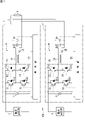
- FIG. 1 is a connection diagram showing an example of a parallel inverter system in which two inverters that operate independently are connected in parallel to an AC electric circuit.
- FIG. 2 is a control block diagram regarding voltage control in the control unit.
- FIG. 3 is a diagram expressing the control block diagram of FIG. 2 as a flow chart.
- FIG. 4 shows the simulation results when the first and second inverters are operated in parallel with the self-sustained output under the same control as in the grid-connected operation.
- FIG. 5 shows the simulation results when the first and second inverters are operated in parallel with the independent output using a reference voltage signal whose frequency is fixed at 60 Hz.
- FIG. 6 shows simulation results when control is performed based on the control block diagram of FIG. FIG.
- FIG. 7 is a simulation result when the parallel inverter system of FIG. 1 and the generator of the commercial power system are operated in parallel.
- FIG. 8(a) is a graph showing an example of the relationship between the inverter output current I and the phase difference ⁇ when the inverters having the phase-locked loop with frequency feedback shown in FIG. 2 are operated in parallel.
- (b) is a vector diagram showing the relationship between equivalent induced electromotive force E, phase difference ⁇ , and AC voltage V.
- phase locked loop used for grid interconnection can achieve phase synchronization by setting vq obtained by dq conversion (Park conversion) to 0 using an AC voltage as a reference signal.
- vq obtained by dq conversion (Park conversion)
- AC voltage AC voltage
- the present disclosure aims to stabilize the parallel operation of inverters that provide independent output to AC electric lines.
- Embodiments of the present disclosure include at least the following as gists thereof.
- This is an inverter that is connected in parallel to an AC electric circuit to which an AC power supply is connected and provides a self-sustaining output. , a voltage sensor that detects the AC voltage of the AC circuit, and a control unit that controls the power conversion unit, wherein the control unit calculates a frequency detection value in a phase-locked loop executed based on the AC voltage.
- a frequency feedback process of adding a frequency correction value obtained by performing proportional integration to the result of comparison between the previous value of the frequency detection value and the frequency reference value is added to the calculation.
- the frequency of the self-sustained output asymptotically approaches the target value and converges. Therefore, when a plurality of such inverters are connected in parallel, or when they are connected in parallel with another AC power supply, stable parallel operation can be performed.
- the control unit determines the voltage phase based on the detection output of the voltage sensor and the internal phase in the phase locked loop. a first calculation for obtaining a first frequency correction value based on the deviation of and adding the first frequency correction value and the second frequency correction value to the frequency reference value to obtain a new frequency detection value A second calculation to obtain and a third calculation to generate a control signal for controlling the output of the power converter based on the new frequency detection value are executed. In this case, especially by performing the second calculation, it is possible to prevent the frequency of the self-sustained output from converging.
- the third calculation includes obtaining a voltage command value based on the new frequency detection value, and determining the deviation between the voltage command value and the AC voltage, obtaining a voltage correction value by performing a proportional operation.
- the proportional calculation instead of the proportional integral calculation, even if there is a difference in the value detected as the AC voltage between the other AC power supplies, the cross current can be suppressed.
- the internal phase has a phase difference with respect to the phase of the AC voltage that changes according to the output current of the power conversion section.
- the phase difference is proportional to the output current, and the phase difference increases as the output current increases. This is similar to the relationship between the output current of a synchronous generator and the internal phase angle.
- an inverter with frequency feedback processing added to a phase-locked loop operates as a kind of virtual synchronous generator. Therefore, the inverter can also be operated in parallel with the synchronous generator.
- the power conversion unit can also convert AC power to DC power, and the control unit converts the AC power of the AC power source into DC power.
- the power converter may also be controlled to convert to electrical power to charge a DC voltage source connected to the DC side of the power converter. Power consumption at the load when an AC power supply (current source) that outputs a current that synchronizes with the voltage of the AC circuit is connected to the AC circuit, such as a grid-connected inverter that uses photovoltaic power generation as a power source. can be forward-converted (AC ⁇ DC) by a self-sustaining output inverter to charge a DC voltage source (including a storage battery).
- a first inverter that provides a self-sustaining output to an AC circuit
- a second inverter that is connected in parallel with the first inverter to the AC circuit and provides a self-sustaining output to the AC circuit.
- a parallel inverter system is also disclosed.
- Each of the first inverter and the second inverter includes a power conversion unit that converts DC power into AC power and supplies power to the AC electric circuit, a voltage sensor that detects the AC voltage of the AC electric circuit, a control unit for controlling the power conversion unit, wherein the control unit includes a previous value of the frequency detection value and a frequency reference value in an operation for calculating a frequency detection value in a phase locked loop executed based on the AC voltage
- a frequency feedback process is added to add a frequency correction value obtained by performing proportional integration on the result of comparison with the value.
- a method for controlling an inverter connected in parallel to an AC electric circuit to which an AC power supply is connected and providing a self-sustaining output wherein a power conversion unit converts DC power into AC power and A control unit that supplies electric power to an AC electric circuit and controls the power conversion unit uses the previous value of the detected frequency value in a calculation for calculating a detected frequency value in a phase-locked loop that is executed based on the AC voltage of the AC electric circuit.
- This is an inverter control method that adds a frequency feedback process for adding a frequency correction value obtained by performing proportional integration on the result of comparison between the frequency reference value and the frequency reference value.
- the frequency of the self-sustaining output asymptotically approaches the target value and converges. Therefore, when a plurality of such inverters are connected in parallel, or when they are connected in parallel with another AC power supply, stable parallel operation can be performed.
- FIG. 1 is a connection diagram showing an example of a parallel inverter system 100 in which two inverters 1 and 2 that operate independently are connected in parallel to an AC electric line 5. As shown in FIG. Although the inverters 1 and 2 can be operated in a grid-connected manner with the commercial power system, the present disclosure shows only the state during self-sustained operation. Two inverters is a minimum configuration example of "plurality", and three or more inverters may be used.
- a DC voltage source 3 is connected to the first inverter 1 .
- the DC voltage source 3 may be a power source such as a photovoltaic panel or a storage battery itself, or may be a circuit via a DC/DC converter as the power source.
- a DC voltage source 4 is connected to the second inverter 2 .
- the first inverter 1 and the second inverter 2 are connected in parallel to the AC electric line 5 .
- a load (AC load) 6 is connected to the AC electric line 5 .
- the first inverter 1 is composed of a control section 1A and a power conversion section 1B.
- the power conversion unit 1B includes a full bridge circuit 10 connected to the DC voltage source 3, an AC reactor 15 provided on two lines on the AC side of the full bridge circuit 10, an AC side capacitor 16, a voltage sensor 17, It comprises a current sensor 18 and a voltage sensor 19, which are connected as shown.
- the full bridge circuit 10 is composed of switching elements 11, 12, 13 and 14 and diodes 11d, 12d, 13d and 14d connected in anti-parallel to these elements.
- the illustrated switching elements 11, 12, 13, and 14 are IGBTs (Insulated Gate Bipolar Transistors), but MOS-FETs (Metal-Oxide-Semiconductor Field Effect Transistors) may be used instead.
- the full bridge circuit 10 is connected across the DC voltage source 3 .
- the voltage sensor 17 detects the DC voltage input from the DC voltage source 3 to the full bridge circuit 10 and sends the detection output to the control section 1A.
- the current sensor 18 detects the current flowing through the AC reactor 15 and sends the detection output to the control section 1A.
- the voltage sensor 19 detects the AC voltage output to the AC electric circuit 5 and sends the detected output to the control section 1A.
- the inverter 1 configured as described above converts DC power input from the DC voltage source 3 into voltage-controlled AC power by a PWM (Pulse Width Modulation) controlled full bridge circuit 10 during self-sustained operation. do. A high frequency ripple included in the AC waveform is suppressed by the AC reactor 15 and the AC side capacitor 16 .
- the AC output of inverter 1 is provided to AC line 5 and supplied to load 6 .
- the second inverter 2 is composed of a control section 2A and a power conversion section 2B.
- the power conversion unit 2B includes a full bridge circuit 20 connected to the DC voltage source 4, an AC reactor 25 provided on two lines on the AC side of the full bridge circuit 20, an AC side capacitor 26, a voltage sensor 27, It comprises a current sensor 28 and a voltage sensor 29, which are connected as shown.
- the full bridge circuit 20 is composed of switching elements 21, 22, 23, 24 and diodes 21d, 22d, 23d, 24d connected in anti-parallel to these, respectively.
- the full bridge circuit 20 is connected across the DC voltage source 4 .
- the voltage sensor 27 detects the DC voltage input from the DC voltage source 4 to the full bridge circuit 20 and sends the detection output to the control section 2A.
- the current sensor 28 detects the current flowing through the AC reactor 25 and sends the detection output to the control section 2A.
- the voltage sensor 29 detects the AC voltage output to the AC electric circuit 5 and sends the detected output to the control section 2A.
- the inverter 2 configured as described above converts the DC power input from the DC voltage source 4 into voltage-controlled AC power by the PWM-controlled full-bridge circuit 20 during self-sustained operation. A high frequency ripple included in the AC waveform is suppressed by the AC reactor 25 and the AC side capacitor 26 .
- the AC output of inverter 2 is provided to AC line 5 and supplied to load 6 .
- Both the control units 1A and 2A in the first inverter 1 and the second inverter include computers, and the computers execute software (computer programs) to realize necessary control functions.
- the software is stored in a storage device (not shown) of the controller.
- FIG. 2 is a control block diagram regarding voltage control in the control unit. Note that this diagram shows the simplest example that does not include a current control loop for the sake of simplification of explanation.
- 3 is a diagram expressing the control block diagram of FIG. 2 as a flow chart.
- the control unit obtains the phase difference detection value ⁇ (step S1).
- the AC voltage va and the internal phase (previous value) ⁇ are input to the phase difference detector B1 to obtain the phase difference detection value ⁇ .
- the control unit obtains the first frequency correction value ⁇ f1 (step S2).
- the phase difference detection value ⁇ becomes the frequency correction value ⁇ f1 through the first proportional integrator B2.
- the control unit obtains a second frequency correction value ⁇ f2 (step S3).
- the adder B5 compares the frequency reference value fo with the previous value of the detected frequency value f, and the difference between them becomes the frequency correction value ⁇ f2 via the second proportional integrator B6.
- the control unit obtains a frequency detection value f (step S4).
- the frequency correction value ⁇ f1 the frequency correction value ⁇ f2, and the frequency reference value fo are added together by the adder B3 to obtain a new frequency detection value f.
- the previous frequency detection value f is used.
- the controller obtains the internal phase ⁇ (step S5).
- the frequency detection value f becomes the internal phase ⁇ through the integrator B4.
- the internal phase .theta. is the output of the phase-locked loop L, and the phase-locked loop L incorporates the frequency feedback loop F as a loop within the loop.
- the controller obtains the voltage command value va * (step S6).
- the voltage command unit B7 outputs the voltage command value va * based on the internal phase ⁇ and the voltage amplitude reference value E0.
- the control unit obtains the voltage correction value ⁇ va (step S7).
- the voltage command value va * and the AC voltage va are compared by an adder B8 and subjected to proportional processing by a proportional device B9 to obtain a voltage correction value .DELTA.va.
- the AC current ia can also be used for the calculation for obtaining the voltage correction value ⁇ va.
- proportional integral control is used to calculate the voltage correction value ⁇ va
- the reactive power due to the cross current flowing between the two inverters increases as the deviation of the AC voltages va of the two inverters increases.
- a deviation, a DC component, and a phase difference occur in the output current.
- proportional control proportional device B9
- the control unit obtains a control signal for the inverter (step S8).
- the PWM signal generator B10 generates a pulse width modulated inverter control signal based on the voltage command value va * and the voltage correction value ⁇ va, and based on this, the inverter gate drive signal is obtained.
- a DC voltage vi is also applied to the PWM signal generator B10.
- the processing shown in the flow chart of FIG. 3 is repeatedly executed while the inverters 1 and 2 are operating independently.
- the phase difference detector B1, the first proportional integrator B2, the adder B3 and the integrator B4 form a phase locked loop L.
- the adder B3, the adder B5, and the second proportional integrator B6 form a frequency feedback loop F.
- Such a frequency feedback loop F does not need to be used for an inverter that performs grid-connected operation instead of isolated operation.
- FIG. 4 shows the simulation results when the first and second inverters are operated in parallel with the self-sustained output under the same control as in the grid-connected operation.
- the horizontal axis in (a), (b), (c) and (d) is common and represents time (0 to 2 seconds).
- the numbers on the vertical axis represent voltage, current or frequency. In this control, the first inverter is operated first, and the operation of the second inverter is started after one second.
- (a) is a waveform diagram in which an AC voltage va and an AC current output by a first inverter are superimposed and displayed.
- the AC voltage va has a larger amplitude, and the AC current has a smaller amplitude.
- (b) is a waveform diagram of two-phase voltages vd (upper) and vq (lower) after dq conversion.
- (c) is the output frequency of the phase locked loop.
- (d) is the output current of the first inverter and the second inverter. From 0 to about 1.1 seconds, the larger amplitude is the first inverter and the smaller amplitude is the second inverter. From about 1.1 seconds to about 1.5 seconds, both overlap each other.
- FIG. 5 shows the simulation results when the first and second inverters are operated in parallel with the independent output using a reference voltage signal whose frequency is fixed at 60 Hz.
- the horizontal axis in (a), (b), (c) and (d) is common and represents time (0 to 10 seconds).
- the numbers on the vertical axis represent voltage, current or frequency.
- the horizontal axis (time axis) just before 10 seconds is enlarged, and the vertical axis is also enlarged for (c) and (d).
- (a) is a waveform diagram in which an AC voltage va and an AC current output by a first inverter are superimposed and displayed.
- the AC voltage va has a larger amplitude, and the AC current oscillates near zero.
- (b) is a waveform diagram of two-phase voltages vd (upper) and vq (lower) after dq conversion.
- (c) is the output frequency of the phase locked loop.
- (d) is the output current of the first inverter and the second inverter. The second inverter starts operating one second later than the first inverter.
- the voltage Vq becomes 0, and the output frequency of the phase-locked loop converges to 60 Hz as shown in (c).
- this control requires a signal line for sharing a common reference voltage signal between the two inverters. Therefore, the signal line is more likely to be affected by noise.
- FIG. 6 shows simulation results when control is performed based on the control block diagram of FIG.
- the horizontal axis in (a), (b), (c) and (d) is common and represents time (0 to 10 seconds).
- the numbers on the vertical axis represent voltage, current or frequency.
- the horizontal axis (time axis) just before 10 seconds is enlarged, and the vertical axis is also enlarged for (c) and (d).
- the proportional gain of the second proportional integrator B6 in the frequency feedback loop F was set to 0.2, and the integration time constant was set to 0.01 seconds.
- (a) is a waveform diagram in which an AC voltage va and an AC current output by a first inverter are superimposed and displayed.
- the AC voltage va has a larger amplitude, and the AC current oscillates near zero.
- (b) is a waveform diagram of two-phase voltages vd (upper) and vq (lower) after dq conversion.
- (c) is the output frequency of the phase locked loop.
- (d) is the output current of the first inverter and the second inverter. The second inverter starts operating one second later than the first inverter.
- the voltage vq does not become 0, but converges to a constant negative value.
- the frequency of the phase-locked loop L generally converges to a constant value as targeted.
- the output current after the second inverter starts operating is equally shared between the two inverters, the power factor is 1, and no DC component is generated. No out of control events occurred and the frequency is stable.
- FIG. 8(a) shows the relationship between the output current I of the inverter (power converter) and the internal phase difference ⁇ when the inverters having the phase-locked loop with frequency feedback shown in FIG. 2 are operated in parallel. It is a graph which shows an example of relationship.
- the phase difference ⁇ is in a proportional relationship with the output current I, and as the output current I increases, the phase difference ⁇ also increases. This is similar to the relationship between the output current of a synchronous generator and the internal phase angle.
- FIG. 8 is a vector diagram showing the relationship between the equivalent induced electromotive force E, the phase difference ⁇ , and the AC voltage V.
- FIG. Here, if the inverter is considered as a synchronous generator with a synchronous reactance of x s , and the phase difference ⁇ is sin ⁇ , the following relationship is obtained. ⁇ ( jxsI )/E That is, an inverter with frequency feedback processing added to a phase-locked loop operates as a kind of virtual synchronous generator (VSG: Virtual Synchronous Generator). Therefore, the inverter can also be operated in parallel with the synchronous generator.
- VSG Virtual Synchronous Generator
- FIG. 7 is a simulation result when the parallel inverter system 100 of FIG. 1 and the generator of the commercial power system are operated in parallel.
- the horizontal axis in (a), (b), (c) and (d) is common and represents time (9.9 to 10.1 seconds).
- the numbers on the vertical axis represent voltage, current or frequency.
- FIG. 7 is a waveform diagram in which the AC voltage va and the AC current output by the first inverter are superimposed and displayed.
- the AC voltage va has a larger amplitude, and the AC current oscillates near zero.
- (b) is a waveform diagram of two-phase voltages vd (upper) and vq (lower) after dq conversion.
- (c) is the output frequency of the phase locked loop.
- (d) is the output current of the first inverter and the second inverter. The generator is disconnected at 10 seconds.
- a high-pass filter for DC component suppression and a low-pass filter for oscillation suppression are provided for the calculation of the current command value.
- the DC component is reduced and the power factor is improved to 0.993.
- the generator was disconnected after 10 seconds, the AC voltage va remained almost unchanged, and the output currents of the two inverters increased to compensate for the current borne by the generator.
- the voltage vq and the output frequency of the phase-locked loop decreased slightly after the parallel-off, the two inverters equally bear half of the load current of 20A.
- phase-locked loop leads the AC voltage in the same way as the synchronous generator, and the phase difference increases in proportion to the output current of the inverter.
- independent output inverters controlled by a phase-locked loop can be operated not only in parallel, but also in parallel with other AC power sources, and can be treated as a virtual synchronous generator.
- the above disclosure can be generalized and expressed as follows.
- the control unit in each of the first inverter (1) and the second inverter (2) shown in FIG. 1 calculates the frequency detection value in the phase locked loop (L) executed based on the AC voltage (Va)
- a frequency feedback process (frequency feedback loop (F)) is added to the calculation to add a frequency correction value ( ⁇ f2) obtained by performing proportional integration on the comparison result between the previous value of the frequency detection value and the frequency reference value.
- ⁇ f2 frequency correction value obtained by performing proportional integration on the comparison result between the previous value of the frequency detection value and the frequency reference value.
- the control unit adjusts the voltage phase based on the detection output of the voltage sensor (19, 29) and the phase-locked loop (L).
- the third calculation includes obtaining the voltage command value (va * ) based on the new frequency detection value (f), and proportional calculation to the deviation between the voltage command value (va * ) and the AC voltage. to determine the voltage correction value ( ⁇ va).
- the proportional calculation instead of the proportional integral calculation, even if there is a difference in the value detected as the AC voltage between the other AC power supplies, the cross current can be suppressed.
- the inverters 1 and 2 in FIG. 1 have been described as independent output inverters, when the DC voltage source is based on a storage battery, the inverters 1 and 2 (power converters 1B and 2B) convert AC power to DC power. may be performed.
- an AC power supply current source
- the control units 1A and 2A convert the AC power of the AC power supply into DC power and control to charge the storage battery connected to the DC side of the power conversion units 1B and 2B.
- the inverters 1 and 2 forward-convert (AC ⁇ DC) the surplus power of the power consumed by the load 6 so that the storage batteries included in the DC voltage sources 3 and 4 can be charged. note that. In this case, the internal phase in the phase locked loop of the inverter lags the phase of the AC voltage.
Landscapes
- Engineering & Computer Science (AREA)
- Power Engineering (AREA)
- Inverter Devices (AREA)
Priority Applications (2)
| Application Number | Priority Date | Filing Date | Title |
|---|---|---|---|
| JP2023503375A JP7613552B2 (ja) | 2021-03-03 | 2021-11-02 | インバータ、並列インバータシステム、及び、インバータの制御方法 |
| US18/278,410 US12463554B2 (en) | 2021-03-03 | 2021-11-02 | Inverter, parallel inverter system, and method of controlling inverter |
Applications Claiming Priority (2)
| Application Number | Priority Date | Filing Date | Title |
|---|---|---|---|
| JP2021-033734 | 2021-03-03 | ||
| JP2021033734 | 2021-03-03 |
Publications (1)
| Publication Number | Publication Date |
|---|---|
| WO2022185614A1 true WO2022185614A1 (ja) | 2022-09-09 |
Family
ID=83154244
Family Applications (1)
| Application Number | Title | Priority Date | Filing Date |
|---|---|---|---|
| PCT/JP2021/040360 Ceased WO2022185614A1 (ja) | 2021-03-03 | 2021-11-02 | インバータ、並列インバータシステム、及び、インバータの制御方法 |
Country Status (3)
| Country | Link |
|---|---|
| US (1) | US12463554B2 (https=) |
| JP (1) | JP7613552B2 (https=) |
| WO (1) | WO2022185614A1 (https=) |
Families Citing this family (2)
| Publication number | Priority date | Publication date | Assignee | Title |
|---|---|---|---|---|
| US12199441B2 (en) * | 2022-02-18 | 2025-01-14 | The University Of North Carolina At Charlotte | Apparatus and method for controlling one or more inverters |
| EP4555616A1 (en) * | 2022-07-11 | 2025-05-21 | Nextracker LLC | Parallel inverter systems and methods |
Citations (3)
| Publication number | Priority date | Publication date | Assignee | Title |
|---|---|---|---|---|
| JP2010161901A (ja) * | 2009-01-09 | 2010-07-22 | Daihen Corp | インバータ制御回路、このインバータ制御回路を備えた系統連系インバータシステム |
| JP2015100224A (ja) * | 2013-11-20 | 2015-05-28 | 株式会社ダイヘン | インバータ回路を制御する制御回路、当該制御回路を備えたインバータ装置、当該インバータ装置を備えた電力システム、および、制御方法 |
| JP2017225214A (ja) * | 2016-06-13 | 2017-12-21 | 新電元工業株式会社 | 三相インバータの並列運転制御方法及び並列運転制御装置 |
Family Cites Families (5)
| Publication number | Priority date | Publication date | Assignee | Title |
|---|---|---|---|---|
| JP4396926B2 (ja) | 2004-02-12 | 2010-01-13 | 東芝三菱電機産業システム株式会社 | 電力変換装置 |
| US9450513B2 (en) | 2013-09-27 | 2016-09-20 | Daihen Corporation | Control circuit and control method for inverter circuit, and control circuit and control method for power conversion circuit |
| WO2017126205A1 (ja) * | 2016-01-20 | 2017-07-27 | 三菱電機株式会社 | 電力変換装置および電力変換システム |
| FI3869682T3 (fi) * | 2020-02-24 | 2024-07-10 | Danfoss As | Menetelmä ja ohjauslaite tehonmuuntimen säätämiseksi |
| JP7387497B2 (ja) * | 2020-03-11 | 2023-11-28 | 株式会社東芝 | 電力変換装置 |
-
2021
- 2021-11-02 WO PCT/JP2021/040360 patent/WO2022185614A1/ja not_active Ceased
- 2021-11-02 US US18/278,410 patent/US12463554B2/en active Active
- 2021-11-02 JP JP2023503375A patent/JP7613552B2/ja active Active
Patent Citations (3)
| Publication number | Priority date | Publication date | Assignee | Title |
|---|---|---|---|---|
| JP2010161901A (ja) * | 2009-01-09 | 2010-07-22 | Daihen Corp | インバータ制御回路、このインバータ制御回路を備えた系統連系インバータシステム |
| JP2015100224A (ja) * | 2013-11-20 | 2015-05-28 | 株式会社ダイヘン | インバータ回路を制御する制御回路、当該制御回路を備えたインバータ装置、当該インバータ装置を備えた電力システム、および、制御方法 |
| JP2017225214A (ja) * | 2016-06-13 | 2017-12-21 | 新電元工業株式会社 | 三相インバータの並列運転制御方法及び並列運転制御装置 |
Also Published As
| Publication number | Publication date |
|---|---|
| US20240136947A1 (en) | 2024-04-25 |
| US20240235421A9 (en) | 2024-07-11 |
| JP7613552B2 (ja) | 2025-01-15 |
| JPWO2022185614A1 (https=) | 2022-09-09 |
| US12463554B2 (en) | 2025-11-04 |
Similar Documents
| Publication | Publication Date | Title |
|---|---|---|
| US8848406B2 (en) | Single-phase voltage type AC/DC converter, three-phase voltage type AC/DC converter, and stabilization control method | |
| CN102299659B (zh) | 用于多相电力转换器的控制的系统以及方法 | |
| US8848400B2 (en) | System and method for reactive power regulation | |
| US10411478B2 (en) | Grid connection power conversion device and disconnection/welding detection method therefor | |
| US20140307494A1 (en) | Power decoupling controller and method for power conversion system | |
| US20130181654A1 (en) | Motor drive system employing an active rectifier | |
| JP6744477B2 (ja) | 無停電電源装置および無停電電源装置の試験方法 | |
| JP2009219263A (ja) | 単相電圧型交直変換装置 | |
| JPH0336930A (ja) | 3相変換装置 | |
| JP7613552B2 (ja) | インバータ、並列インバータシステム、及び、インバータの制御方法 | |
| JP2011055591A (ja) | インバータ制御回路、このインバータ制御回路を備えた系統連系インバータシステム | |
| JP4664836B2 (ja) | 三相電圧型交直変換装置 | |
| JP7136368B2 (ja) | 電力変換装置 | |
| JP4052154B2 (ja) | 分散型電源の出力安定化装置とその制御方法。 | |
| JP5616411B2 (ja) | 単相電圧型交直変換装置 | |
| JP5616412B2 (ja) | 単相電圧型交直変換装置 | |
| JP7830512B2 (ja) | 電力変換装置及び電力変換装置の制御方法 | |
| JP7722070B2 (ja) | 電力変換装置 | |
| Vlad et al. | Controlling the grid inverter powers through the Synchronous Reference Frame Phase Locked Loop | |
| WO2014050934A1 (ja) | 単相電圧型交直変換装置 | |
| Kumar et al. | Improved DQ Based V & I Control in H-Bridge Inverter | |
| WO2014050758A1 (ja) | 単相電圧型交直変換装置 | |
| WO2014050760A1 (ja) | 単相電圧型交直変換装置 | |
| JP2010161902A (ja) | インバータ制御回路、このインバータ制御回路を備えた系統連系インバータシステム | |
| JPH0720370B2 (ja) | 電力変換器の制御回路 |
Legal Events
| Date | Code | Title | Description |
|---|---|---|---|
| 121 | Ep: the epo has been informed by wipo that ep was designated in this application |
Ref document number: 21929174 Country of ref document: EP Kind code of ref document: A1 |
|
| WWE | Wipo information: entry into national phase |
Ref document number: 2023503375 Country of ref document: JP |
|
| WWE | Wipo information: entry into national phase |
Ref document number: 18278410 Country of ref document: US |
|
| NENP | Non-entry into the national phase |
Ref country code: DE |
|
| 122 | Ep: pct application non-entry in european phase |
Ref document number: 21929174 Country of ref document: EP Kind code of ref document: A1 |
|
| WWG | Wipo information: grant in national office |
Ref document number: 18278410 Country of ref document: US |