WO2022185482A1 - 情報処理装置、情報処理方法、及びプログラム - Google Patents
情報処理装置、情報処理方法、及びプログラム Download PDFInfo
- Publication number
- WO2022185482A1 WO2022185482A1 PCT/JP2021/008457 JP2021008457W WO2022185482A1 WO 2022185482 A1 WO2022185482 A1 WO 2022185482A1 JP 2021008457 W JP2021008457 W JP 2021008457W WO 2022185482 A1 WO2022185482 A1 WO 2022185482A1
- Authority
- WO
- WIPO (PCT)
- Prior art keywords
- information
- unit
- image data
- information processing
- camera
- Prior art date
- Legal status (The legal status is an assumption and is not a legal conclusion. Google has not performed a legal analysis and makes no representation as to the accuracy of the status listed.)
- Ceased
Links
Images









Classifications
-
- G—PHYSICS
- G06—COMPUTING OR CALCULATING; COUNTING
- G06T—IMAGE DATA PROCESSING OR GENERATION, IN GENERAL
- G06T5/00—Image enhancement or restoration
- G06T5/70—Denoising; Smoothing
-
- G—PHYSICS
- G01—MEASURING; TESTING
- G01C—MEASURING DISTANCES, LEVELS OR BEARINGS; SURVEYING; NAVIGATION; GYROSCOPIC INSTRUMENTS; PHOTOGRAMMETRY OR VIDEOGRAMMETRY
- G01C11/00—Photogrammetry or videogrammetry, e.g. stereogrammetry; Photographic surveying
- G01C11/02—Picture taking arrangements specially adapted for photogrammetry or photographic surveying, e.g. controlling overlapping of pictures
-
- G—PHYSICS
- G01—MEASURING; TESTING
- G01C—MEASURING DISTANCES, LEVELS OR BEARINGS; SURVEYING; NAVIGATION; GYROSCOPIC INSTRUMENTS; PHOTOGRAMMETRY OR VIDEOGRAMMETRY
- G01C21/00—Navigation; Navigational instruments not provided for in groups G01C1/00 - G01C19/00
- G01C21/26—Navigation; Navigational instruments not provided for in groups G01C1/00 - G01C19/00 specially adapted for navigation in a road network
-
- G—PHYSICS
- G01—MEASURING; TESTING
- G01C—MEASURING DISTANCES, LEVELS OR BEARINGS; SURVEYING; NAVIGATION; GYROSCOPIC INSTRUMENTS; PHOTOGRAMMETRY OR VIDEOGRAMMETRY
- G01C7/00—Tracing profiles
- G01C7/02—Tracing profiles of land surfaces
- G01C7/04—Tracing profiles of land surfaces involving a vehicle which moves along the profile to be traced
-
- G—PHYSICS
- G05—CONTROLLING; REGULATING
- G05D—SYSTEMS FOR CONTROLLING OR REGULATING NON-ELECTRIC VARIABLES
- G05D1/00—Control of position, course, altitude or attitude of land, water, air or space vehicles, e.g. using automatic pilots
- G05D1/02—Control of position or course in two dimensions
-
- G—PHYSICS
- G06—COMPUTING OR CALCULATING; COUNTING
- G06T—IMAGE DATA PROCESSING OR GENERATION, IN GENERAL
- G06T5/00—Image enhancement or restoration
- G06T5/60—Image enhancement or restoration using machine learning, e.g. neural networks
-
- G—PHYSICS
- G06—COMPUTING OR CALCULATING; COUNTING
- G06T—IMAGE DATA PROCESSING OR GENERATION, IN GENERAL
- G06T7/00—Image analysis
- G06T7/50—Depth or shape recovery
- G06T7/55—Depth or shape recovery from multiple images
- G06T7/579—Depth or shape recovery from multiple images from motion
-
- G—PHYSICS
- G01—MEASURING; TESTING
- G01B—MEASURING LENGTH, THICKNESS OR SIMILAR LINEAR DIMENSIONS; MEASURING ANGLES; MEASURING AREAS; MEASURING IRREGULARITIES OF SURFACES OR CONTOURS
- G01B11/00—Measuring arrangements characterised by the use of optical techniques
-
- G—PHYSICS
- G06—COMPUTING OR CALCULATING; COUNTING
- G06T—IMAGE DATA PROCESSING OR GENERATION, IN GENERAL
- G06T2207/00—Indexing scheme for image analysis or image enhancement
- G06T2207/10—Image acquisition modality
- G06T2207/10028—Range image; Depth image; 3D point clouds
-
- G—PHYSICS
- G06—COMPUTING OR CALCULATING; COUNTING
- G06T—IMAGE DATA PROCESSING OR GENERATION, IN GENERAL
- G06T2207/00—Indexing scheme for image analysis or image enhancement
- G06T2207/20—Special algorithmic details
- G06T2207/20081—Training; Learning
-
- G—PHYSICS
- G06—COMPUTING OR CALCULATING; COUNTING
- G06T—IMAGE DATA PROCESSING OR GENERATION, IN GENERAL
- G06T2207/00—Indexing scheme for image analysis or image enhancement
- G06T2207/20—Special algorithmic details
- G06T2207/20084—Artificial neural networks [ANN]
-
- G—PHYSICS
- G06—COMPUTING OR CALCULATING; COUNTING
- G06T—IMAGE DATA PROCESSING OR GENERATION, IN GENERAL
- G06T2207/00—Indexing scheme for image analysis or image enhancement
- G06T2207/30—Subject of image; Context of image processing
- G06T2207/30248—Vehicle exterior or interior
- G06T2207/30252—Vehicle exterior; Vicinity of vehicle
Definitions
- the present invention relates to an information processing device, an information processing method, and a program.
- SLAM Simultaneous Localization and Mappin
- VSLAM Visual SLAM
- An embodiment of the present invention has been made in view of the above problems, and enables to appropriately set the filter coefficients of one or more filters applied to point cloud information output by VSLAM processing.
- an information processing apparatus acquires first point cloud information representing three-dimensional position information using image data captured by a first camera.
- a filter unit that outputs second point cloud information obtained by reducing noise of the first point cloud information using one or more filters; and a learning test including image data captured by a second camera.
- Observation including a filter coefficient estimation model learned in advance using data and training data based on third point group information representing three-dimensional position information acquired by a position sensor, and image data captured by the first camera and a setting unit configured to set filter coefficients of the one or more filters using data.
- FIG. 4 is a diagram (1) for explaining filter processing according to the first embodiment
- FIG. 2B is a diagram (2) for explaining filter processing according to the first embodiment
- FIG. 3 is a diagram (3) for explaining filter processing according to the first embodiment
- FIG. 4 is a diagram (4) for explaining filter processing according to the first embodiment
- FIG. 4 is a diagram (1) for explaining filter processing according to the first embodiment
- FIG. 2B is a diagram (2) for explaining filter processing according to the first embodiment
- FIG. 3 is a diagram (3) for explaining filter processing according to the first embodiment
- FIG. 4 is a diagram (4) for explaining filter processing according to the first embodiment
- FIG 5 is a diagram (5) for explaining filter processing according to the first embodiment
- 4 is a flow chart showing an example of processing of the information processing apparatus according to the first embodiment
- 1 is a diagram (1) for explaining an application example of the information processing apparatus according to the first embodiment
- FIG. FIG. 2B is a diagram (2) for explaining an application example of the information processing apparatus according to the first embodiment
- 1 is a diagram (1) showing an example of an environment for acquiring learning data according to the first embodiment
- FIG. FIG. 2 is a diagram (2) showing an example of an environment for acquiring learning data according to the first embodiment
- 6 is a flowchart illustrating an example of acquisition processing according to the first embodiment
- It is a figure which shows the example of the learning environment which concerns on 1st Embodiment.
- FIG. 4 is a flowchart showing an example of learning processing according to the first embodiment; It is a figure which shows the example of the system configuration
- FIG. 11 is a diagram for explaining an outline of processing of an information processing system according to a second embodiment; FIG.
- the information processing apparatus can be applied to various mobile objects such as automobiles, robots, and drones.
- various mobile objects such as automobiles, robots, and drones.
- the information processing device is provided in a vehicle such as an automobile will be described.
- FIG. 1 is a diagram showing an example of the overall configuration of a vehicle equipped with an information processing device according to one embodiment.
- the vehicle 1 includes an information processing device 10, one or more cameras 12, a position sensor 14, a display device 16, and the like.
- Each component described above is communicably connected by, for example, an in-vehicle network, a wired cable, or wireless communication.
- the vehicle 1 is an example of a moving body on which the information processing device 10 according to the present embodiment is mounted.
- the mobile object is not limited to the vehicle 1, and may be, for example, a robot that moves with legs or the like, a manned or unmanned aircraft, or any other device or machine that has a mobile function.
- the camera 12 is a photographing device that photographs the surroundings of the vehicle 1, converts it into moving image data (hereinafter referred to as image data) in a predetermined format, and outputs the data.
- image data moving image data
- the vehicle 1 is provided with four cameras 12A to 12D facing different photographing areas E1 to E4.
- "camera 12" is used when indicating any camera among the four cameras 12A to 12D.
- "photographing area E" is used.
- the number of cameras 12 and shooting areas E shown in FIG. 1 is an example, and the number may be one or more.
- the camera 12A is provided facing the imaging area E1 in front of the vehicle 1, and the camera 12B is provided facing the imaging area E2 on the side of the vehicle 1.
- the camera 12C is provided facing another lateral imaging area E3 of the vehicle 1, and the camera 12D is provided facing the imaging area E4 behind the vehicle 1.
- the position sensor 14 is a sensor that acquires point cloud information representing three-dimensional position information around the vehicle 1 .
- the position sensor 14 can apply LIDAR (Laser Imaging Detection and Ranging) that measures scattered light for pulsed laser light and acquires an image showing the distance to the object.
- LIDAR Laser Imaging Detection and Ranging
- the position sensor 14 is provided toward the rear of the vehicle 1 as an example.
- the display device 16 is, for example, a display device such as an LCD (Liquid Crystal Display) or an organic EL (Electro-Luminescence), or various apparatuses or devices having a display function for displaying various types of information.
- a display device such as an LCD (Liquid Crystal Display) or an organic EL (Electro-Luminescence), or various apparatuses or devices having a display function for displaying various types of information.
- the information processing device 10 is a computer that executes Visual SLAM (hereinafter referred to as VSLAM) processing that performs SLAM (Simultaneous Localization and Mapping) processing using image data captured by the camera 12 .
- VSLAM Visual SLAM
- the information processing device 10 is communicably connected to one or more ECUs (Electronic Control Units) 3 mounted on the vehicle 1 via an in-vehicle network or the like. Note that the information processing device 10 may be one of the ECUs mounted on the vehicle 1 .
- FIG. 2 is a diagram illustrating an example of a hardware configuration of an information processing apparatus according to one embodiment
- the information processing apparatus 10 has a computer configuration, and includes, for example, a CPU (Central Processing Unit) 201, a memory 202, a storage device 203, an I/F (Interface) 204, a bus 208, and the like. Further, the information processing apparatus 10 may have an input device 205, an output device 206, a communication device 207, or the like.
- a CPU Central Processing Unit
- the CPU 201 is a processor that implements each function of the information processing apparatus 10 by executing a program stored in a storage medium such as the storage device 203, for example.
- the memory 202 includes, for example, a RAM (Random Access Memory) that is a volatile memory used as a work area for the CPU 201, and a ROM (Read Only Memory) that is a non-volatile memory that stores a program for starting the CPU 201. ) etc. are included.
- the storage device 203 is, for example, a large-capacity storage device such as an SSD (Solid State Drive) or HDD (Hard Disk Drive).
- the I/F 204 includes various interfaces for connecting the camera 12, the position sensor 14, the display device 16, the ECU 3, and the like to the information processing device 10, for example.
- the input device 205 includes various devices (for example, keyboards, touch panels, pointing devices, microphones, switches, buttons, sensors, etc.) that receive inputs from the outside.
- the output device 206 includes various devices (eg, displays, speakers, indicators, etc.) that output to the outside.
- Communication equipment 207 includes various communication devices for communicating with other equipment over wired or wireless networks.
- a bus 208 is connected to each component described above, and transmits, for example, address signals, data signals, and various control signals.
- the hardware configuration of the information processing apparatus 10 shown in FIG. 2 is an example.
- the information processing apparatus 10 may have an ASIC (Application Specific Integrated Circuit) for image processing, a DSP (Digital Signal Processor), or the like.
- the input device 205 and the output device 206 may be an integrated display input device such as a touch panel display, or may not be included in the information processing apparatus 10 .
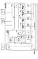
- FIG. 3 is a diagram illustrating an example of the functional configuration of the information processing apparatus according to the first embodiment;
- the information processing apparatus 10 implements an input unit 310, an acquisition unit 320, a filter unit 330, a setting unit 340, an output unit 350, and the like, for example, by executing a predetermined program in the CPU 201 of FIG.
- the functional configurations described above may be realized by hardware. For ease of explanation, the following explanation will be made assuming that the number of cameras 12 is one.
- the input unit 310 acquires image data (moving image data) captured by the camera (first camera) 12 using, for example, the I/F 204 in FIG. Output.
- the acquisition unit 320 performs VSLAM processing on the image data captured by the camera 12 to obtain point group information (hereinafter referred to as first point group information) representing three-dimensional position information in the imaging region E of the camera 12. Execute the acquisition process to acquire the .
- Acquisition unit 320 includes, for example, feature amount extraction unit 321, matching unit 322, self-position estimation unit 323, three-dimensional reconstruction unit 324, storage unit 325, correction unit 327, and the like.
- the feature amount extraction unit 321 executes feature amount extraction processing for extracting feature amounts from a plurality of frames with different shooting timings, which are included in the image data acquired from the input unit 310, and outputs the extracted feature amounts to the matching unit 322. do. Also, as a preferred example, the feature quantity extraction unit 321 outputs the number of features obtained by the feature quantity extraction process to the setting unit 340 as observation data.
- the matching unit 322 uses the feature amounts of the plurality of frames output by the feature amount extraction unit 321 to perform a matching process that identifies a plurality of corresponding points (hereinafter referred to as matching points) between the plurality of frames, The matching result is output to self-position estimation section 323 .
- the multiple frames are, for example, two continuous frames.
- the matching unit 322 outputs the matching number obtained by the matching process to the setting unit 340 as observation data.
- the environment map information 326 is map information representing the surrounding environment of the vehicle (an example of a moving body) 1.
- the environment map information 326 stores position information of each detection point and self-position information of the vehicle 1 in a three-dimensional coordinate space with a predetermined position in the real space as the origin.
- the predetermined position in the real space may be determined, for example, based on preset conditions.
- the predetermined position may be the position of the vehicle 1 when the information processing device 10 starts executing information processing according to the present embodiment.
- the position of the vehicle 1 when the vehicle 1 behaves to indicate the parking scene may be set as the predetermined position.
- the timing for determining the predetermined position is not limited to the parking scene.
- the self-position estimation unit 323 uses a plurality of matching points acquired from the matching unit 322 to estimate the self-position relative to the captured image by projective transformation or the like.
- the self-position includes information on the position (three-dimensional coordinates) and tilt (rotation) of the camera 12, and the self-position estimation unit 323 stores this in the environment map information 326 as self-position information.
- the three-dimensional reconstruction unit 324 performs perspective projection conversion processing using the movement amount (translation amount and rotation amount) of the self-position estimated by the self-position estimation unit 323, and obtains the three-dimensional coordinates of the matching point (relative to the self-position coordinates).
- the three-dimensional reconstruction unit 324 stores the determined three-dimensional coordinates in the environmental map information 326 as peripheral position information. As a result, new peripheral position information and self-position information are sequentially added to the environment map information 326 as the vehicle 1 on which the camera 12 is mounted moves.
- the storage unit 325 is implemented by, for example, the memory 202 in FIG. 2, and stores various information such as the environment map information 326, data, or programs.
- the correction unit 327 calculates the sum of the distance differences in the three-dimensional space between the previously calculated three-dimensional coordinates and the newly calculated three-dimensional coordinates for the points matched multiple times between the plurality of frames. is minimized, for example, the method of least squares or the like is used to correct the position information and self-position information registered in the environment map information 326 . Note that the correction unit 327 may correct the movement amount (translation amount and rotation amount) of the self-position used in the process of calculating the self-position information and the peripheral position information.
- the acquisition unit 320 may acquire first point group information (environment map information 326) representing three-dimensional position information using image data captured by a camera through VSALM processing.
- the specific configuration may be another configuration.
- the filter unit 330 uses one or more filters to obtain point cloud information (hereinafter referred to as second point group information).
- the filter unit 330 includes a spatial outlier removing unit 331, a spatial smoothing processing unit 332, a temporal outlier correcting unit 333, and a temporal smoothing processing unit 334 as an example of one or more filters. .
- the spatial outlier removing unit 331 uses one or more filter coefficients (eg, coefficients a, b, and c) set by the setting unit 340 to perform outlier removing processing for the space at the same time. For example, the spatial outlier removal unit 331 performs distance-based outlier removal processing c times such that each point is removed if the sum of the distances from a surrounding a points is equal to or greater than a threshold value b. Alternatively, the spatial outlier removing unit 331 determines that, for each point, the distance from a surrounding a points is (average value of a surroundings) ⁇ (standard deviation of a surroundings) ⁇ b times or more. It is also possible to perform outlier removal processing c times based on statistics such as removing outliers. Note that the above coefficients a, b, and c are examples of one or more filter coefficients 342 set in the spatial outlier removing unit 331 by the setting unit 340 .
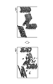
- FIG. 4A is a diagram showing an image of an example of spatial outlier removal processing.
- the first point cloud information acquired by the acquisition unit 320 through VSLAM processing contains a lot of noise, for example, like the point cloud information 411 shown in FIG. 4A.
- the spatial outlier remover 331 obtains point cloud information 412 by removing (or reducing) noise (unnecessary points) from the point cloud information 411 .
- the spatial smoothing processing unit 332 uses one or more filter coefficients (eg, coefficients d and e) set by the setting unit 340 to perform smoothing processing on the space at the same time.
- filter coefficients eg, coefficients d and e
- FIG. 4B is a diagram showing an image of an example of spatial smoothing processing.
- the spatial smoothing processing unit 332 generates an image 421 by meshing the point group information 412 output by the spatial outlier removing unit 331 and shown in FIG.
- the spatial smoothing processing unit 332 can obtain smoothed point group information 422 as shown in FIG. 4B, for example, by converting the meshed image 421 into a point group again at the sampling interval e.
- the above coefficients d and e are examples of one or more filter coefficients 343 that the setting unit 340 sets in the spatial smoothing processing unit 332 .
- the time outlier correction unit 333 uses one or more filter coefficients (for example, coefficients f, g, h, i, j) set by the setting unit 340 to perform outlier removal processing on data strings in the time direction. do.
- the time outlier correction unit 333 partitions the three-dimensional space into unit cubes (f 3 ) with the self-position as the origin, and extracts partitions with scores equal to or greater than the threshold g. Further, the time outlier correction unit 333 combines with the past h frames from which the self-movement vector has been subtracted, and performs removal and complement processing such that effective sections are deleted when they are equal to or less than the threshold i, and added when they are equal to or greater than the threshold j.
- the above coefficients f, g, h, i, and j are examples of one or more filter coefficients 344 that the setting unit 340 sets in the time outlier correction unit 333 .
- FIG. 4C is a diagram showing an image of an example of spatial outlier correction processing executed by the temporal outlier correction unit 333.
- FIG. 4C For example, if the spatial deviation correction process is performed on the point cloud information 422 as shown in FIG. etc. are removed, and the suddenly missing points in the past frames are interpolated. As a result, the point cloud information 431 corrected for noise and omission is obtained from the point cloud information 422 .
- the temporal smoothing processing unit 334 uses one or more coefficients (eg, coefficients k and l) set by the setting unit 340 to perform temporal smoothing processing on the data string in the time direction.
- coefficients eg, coefficients k and l
- FIG. 4D is a diagram showing an image of an example of temporal smoothing processing.
- the temporal smoothing processing unit 334 uses the k past frames obtained by subtracting the self-motion vector from the point group information 431 output by the time outlier correction unit 333, and calculates the effective area defined by the time outlier correction unit 333.
- a weighted moving average process with a weight of l is executed for each time.
- point group information 521 moving averaged (smoothed) in the time direction is obtained.
- the above coefficients k and l are examples of one or more filter coefficients 345 that the setting unit 340 sets in the time smoothing processing unit 334 .
- the filter unit 330 outputs the second point cloud information obtained by reducing the noise of the first point cloud information acquired by the acquisition unit 320 through the VSLAM processing.
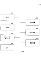
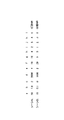
- FIG. 4E shows an example of a combination of filter coefficients (strong NR) suitable for observation data with more point cloud noise and an example of a combination of filter coefficients (weak NR) suitable for observation data with less point cloud noise.
- the information processing apparatus 10 has a setting section 340 that dynamically sets one or more filter coefficients of the filter section 330 according to moving image data captured by the camera 12 .
- the setting unit 340 performs a setting process of setting one or more filter coefficients of the filter unit 330 using a filter coefficient estimation model 341 learned in advance by machine learning and observation data including image data captured by the camera 12. Run.
- the filter coefficient estimation model 341 uses test data for learning including image data captured by a camera and point cloud information (hereinafter referred to as third point cloud information) obtained by the position sensor 14 such as LIDAR. It is a neural network that has been trained using data.
- the test data for learning of the filter coefficient estimation model 341 and the observation data include the number of features indicating the number of extracted feature amounts by the feature amount extraction unit 321, the number of matching points indicating the number of matching performed by the matching unit 322, and the like. Contains data.
- the learning test data and observation data for the filter coefficient estimation model 341 include vehicle information acquired from the vehicle 1, such as vehicle speed information, gear information, and parking mode (parallel or tandem) selected by the user. May be included.
- the learning test data and observation data for the filter coefficient estimation model 341 include image data captured by a camera, the feature number output by the feature amount extraction unit 321, and the matching number output by the matching unit 322. The following description is given assuming that
- the filter coefficient estimation model 341 has a difference between the second point group information output by the filter unit 330 and the third point group information acquired by the position sensor 14 when the above observation data is input, which is equal to or less than a threshold. It is learned in advance so as to output a filter coefficient that becomes
- the term "difference” means the sum of distances, which is the difference between the positions of corresponding points obtained by performing matching processing on two pieces of point group information.
- the setting unit 340 uses the observation data including the image data output by the input unit 310, the feature number output by the feature amount extraction unit 321, and the matching number output by the matching unit 322 as filter coefficient estimation. Enter the model.
- the filter coefficient estimation model 341 outputs filter coefficients 342 to 345 to be set in the filter section 330 according to the observed data.
- the setting unit 340 sets the filter coefficients 342 to 345 output by the filter coefficient estimation model 341 in the filter unit 330 .
- the setting unit 340 can appropriately set the filter coefficients of one or more filters applied to the point cloud information output in the VSLAM process.
- the learning environment and learning process for the filter coefficient estimation model 341 will be described later.
- the output unit 350 outputs the noise-reduced second point group information 335 output by the filter unit 330 to another information processing device such as the ECU 2 included in the vehicle 1 .
- the output unit 350 outputs the second point group information 335 output by the filter unit 330 to an ECU that assists driving or an ECU that controls automatic driving.
- the output unit 350 creates various display screens, such as a display screen displaying three-dimensional objects around the vehicle 1, based on the second point group information 335 output by the filter unit 330. , the display device 16 or the like.
- FIG. 1 shows an example of the process executed by the information processing apparatus 10 described with reference to FIG.
- step S501 the input unit 310 acquires image data (moving image data) captured by the camera 12.
- the input unit 310 also outputs the acquired image data to the acquisition unit 320 and the setting unit 340 .
- step S502 the feature amount extraction unit 321 of the acquisition unit 320 executes feature amount extraction processing for extracting feature amounts from a plurality of frames of the image data acquired from the input unit 310, and sends the extracted feature amount to the matching unit 322. Output.
- the feature amount extraction unit 321 outputs the number of features indicating the number of extracted feature amounts to the setting unit 340 .
- step S ⁇ b>503 the matching unit 322 of the acquisition unit 320 uses the feature amounts of the frames output by the feature amount extraction unit 321 to execute matching processing to identify corresponding points between the frames. The result is output to the self-position estimation unit 323 or the like. Also, the matching unit 322 outputs the matching number obtained by the matching process to the setting unit 340 .
- step S504 based on the matching result output by the matching unit 322, the self-position estimation unit 323 of the acquisition unit 320 executes self-position estimation processing, and the three-dimensional restoration unit 324 executes three-dimensional restoration.
- the correction unit 327 corrects the result of the self-position estimation process and the result of the three-dimensional restoration.
- the acquisition unit 320 can perform VSLAM processing on the image data captured by the camera 12 and acquire the first point group information representing the three-dimensional position information.
- step S505 the setting unit 340 uses the image data acquired from the input unit 310, the number of features acquired from the feature quantity extraction unit 321, and the number of matching acquired from the matching unit 322 as observation data to estimate learned filter coefficients. Input to model 341 .
- the filter coefficient estimation model 341 outputs one or more filter coefficients (for example, coefficients a to l described above) of the filter unit 330 corresponding to the image data captured by the camera 12 .
- the setting unit 340 sets one or more filter coefficients output by the filter coefficient estimation model 341 to the filter unit 330 .
- the spatial outlier removing unit 331 of the filtering unit 330 uses one or more filter coefficients set by the setting unit 340 to remove the spatial Perform outlier removal processing.
- the spatial outlier removing unit 331 uses the coefficients a to c set by the setting unit 340 to perform the spatial outlier removing process described above.
- the spatial smoothing processing unit 332 of the filtering unit 330 uses one or more filter coefficients set by the setting unit 340 to perform spatial Execute the smoothing process.
- the spatial smoothing processing unit 332 uses the coefficients d and e set by the setting unit 340 to perform the spatial smoothing processing described above.
- step S508 the time outlier value correction unit 333 of the filter unit 330 uses one or more filter coefficients set by the setting unit 340 to correct the point cloud information processed by the spatial smoothing unit 332. Perform outlier correction processing.
- the out-of-time value correction unit 333 uses coefficients f to j set by the setting unit 340 to perform the out-of-time correction process described above.
- the temporal smoothing processing unit 334 of the filtering unit 330 uses one or more filter coefficients set by the setting unit 340 to perform time Execute the smoothing process.
- the temporal smoothing processing unit 334 uses coefficients k and l set by the setting unit 340 to perform the temporal smoothing processing described above.
- the filter unit 330 outputs the second point cloud information obtained by reducing the noise of the first point cloud information acquired by the acquisition unit 320 to the output unit 350 or the like.
- step S510 the information processing apparatus 10 repeatedly executes the processes of steps S501 to S509 until the process ends (for example, until an end instruction is received).
- processing of the information processing apparatus 10 shown in FIG. 5 is an example.
- the processing order of the four filters included in the filter unit 330 may be another order.
- the number of four filters included in the filter unit 330 may be one or more.
- the observation data input to the setting unit 340 may not include the number of features output by the feature quantity extraction unit 321 or the matching unit 322. Furthermore, in the process of setting the filter coefficients in step S505, the observation data input to the setting unit 340 may include vehicle information of the vehicle 1 .
- the information processing apparatus 10 it is possible to appropriately set the filter coefficients of one or more filters applied to the first point cloud information output in the VSLAM process. Thereby, the information processing apparatus 10 can output the second point cloud information obtained by reducing the noise of the first point cloud information output by the VSLAM process.
- the second point group information whose noise has been reduced by the information processing apparatus 10 is required to be more accurate point group information, such as an automatic driving system or a driving support system mounted on a vehicle, for example. It can be suitably applied to a system that In addition, the second point group information whose noise has been reduced by the information processing device 10 is not limited to the vehicle 1 such as an automobile, and can be applied to various moving devices (moving bodies) such as robots and drones having a moving function. can do.
- the second point group information whose noise has been reduced by the information processing device 10 can be synthesized from an arbitrary field of view using, for example, a projection image obtained by projecting the photographed image around the vehicle 1 onto a virtual projection plane. It can also be suitably applied to techniques for generating images. For example, three-dimensional objects around the vehicle 1 can be detected based on point cloud information with noise reduced by the information processing apparatus 10 according to the present embodiment, and shape control of the projection surface of the bird's-eye view image can be performed.
- the output unit 350 of the information processing device 10 displays a bird's-eye view image on the display device 16 using a projection image obtained by projecting image data captured by the cameras 12A to 12D in FIG. 1 onto a bowl-shaped projection plane.
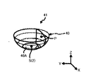
- FIG. 6A is a schematic diagram showing an example of the reference projection plane 40.
- FIG. FIG. 6B is a schematic diagram showing an example of the projection shape 41 determined by the output unit 350, for example.
- the reference projection plane 40 has a bottom surface 40A and side wall surfaces 40B. This is a three-dimensional model that is virtually formed in a virtual space designated as S.
- the output unit 350 transforms the reference projection plane 40 shown in FIG. 6A based on the surrounding position information stored in the environment map information 326 and the self-position information of the moving body 2 to obtain the projection shape 41 shown in FIG. 6B. Determine the modified projection plane 42 as .
- This transformation of the reference projection plane is performed, for example, on the three-dimensional coordinates closest to the vehicle 1 in the peripheral position information.
- the output unit 350 can more appropriately determine the modified projection plane 42 .
- the information processing apparatus 10 can detect surrounding three-dimensional objects with higher accuracy. Therefore, based on the point group information, the output unit 350 may generate 3D objects such as three-dimensional objects (vehicles, etc.) located in the vicinity in the bird's-eye view image.
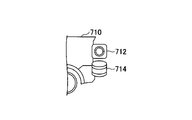
- ⁇ Learning data acquisition environment> (Configuration example) 7A and 7B are diagrams showing examples of learning data acquisition environments according to the first embodiment. Learning test data and teacher data used for learning the filter coefficient estimation model (neural network) 341, as shown in FIG. get.
- the information processing device 700 has, for example, a computer hardware configuration as shown in FIG.
- the information processing device 700 may be the same information processing device as the information processing device 10 in FIG. 3, or may be a different information processing device.
- the camera 712 and the position sensor 714 are provided on a moving object such as a vehicle 710 in close proximity to each other and facing the same direction.
- the camera (second camera) 712 in FIGS. 7A and 7B may be the same camera as the camera 12 in FIG. 3, or may be a different camera.
- the position sensor 714 may be the same position sensor as the position sensor 14, or may be a different position sensor.
- FIG. 8 is a flowchart illustrating an example of acquisition processing according to the first embodiment. This process shows an example of the learning data acquisition process executed by the information processing apparatus 700 in FIG. 7A.
- the information processing apparatus 700 stores the image data 701 captured by the camera 712 in a storage unit such as the storage device 203, and three-dimensional point group information (hereinafter referred to as third point group information) output by the position sensor 714. 3) is stored in another storage area of the storage unit.
- the information processing apparatus 700 simultaneously executes the processes of steps S801 and S802, and stores the image data 701 and the third point cloud information 702 so that they can be output synchronously by, for example, time stamps.
- storing so that they can be output in synchronism means that the information processing apparatus 700 stores the image data 701 and the third point group information 702 in such a manner that the respective acquisition times correspond to each other.
- the storage unit that stores the image data 701 and the third point group information 702 may be, for example, the storage device 203 provided in the information processing apparatus 700, or may be stored in the information processing apparatus 700 via a communication network. It may be an external device such as a storage server that can communicate with.
- step S803 the information processing apparatus 700 repeatedly executes the processes of steps S801 and S802 until the process ends (for example, until an end instruction is received).
- FIG. 9 is a diagram showing an example of a learning environment according to the first embodiment.
- the information processing apparatus (learning environment) 900 has, for example, a computer hardware configuration as shown in FIG. 2, and implements a functional configuration as shown in FIG. 9 by executing a predetermined program.
- the information processing device 900 has an input unit 910, a first acquisition unit 920, a filter unit 930, a learning control unit 940, a second acquisition unit 950, a difference extraction unit 960, and the like. It should be noted that at least part of the functional configurations described above may be realized by hardware.
- the input unit 910 acquires image data (moving image data) 701 captured by the camera 712 and outputs it to the first acquisition unit 920, the learning control unit 940, and the like.
- the first acquisition unit 920 has the same configuration as the acquisition unit 320 in FIG. Execute the acquisition process to acquire the point cloud information of . Note that the internal configuration of the first acquisition unit 920 is the same as that of the acquisition unit 320 described with reference to FIG. 3, so description thereof will be omitted here.
- the filter unit 930 has the same configuration as the filter unit 330 in FIG. Filtering is performed to output the second point cloud information 335 in which . Note that the internal configuration of the filter unit 930 is the same as that of the filter unit 330 described with reference to FIG. 3, so description thereof will be omitted here.
- the second acquisition unit 950 acquires the third point cloud information 702 representing the three-dimensional positional information acquired by the position sensor 714 and outputs it to the difference extraction unit 960 .
- the difference extraction unit 960 extracts the third point cloud information 702 and the second point cloud information 335 output by the filter unit 930. Scan matching is performed with and the difference is extracted.
- scan matching is a technique for performing point group registration using algorithms such as ICP (Iterative Closest Point) and NDT (Normal Distribution Transform).
- ICP Iterative Closest Point
- NDT Normal Distribution Transform
- the difference in the positions of the corresponding points between the two point groups can be obtained as the distance, and the sum of the distances can be obtained as the difference.
- the difference extraction unit 960 performs scan matching on the third point group information 702 and the second point group information 335, and learns the difference between the third point group information and the second point group information 335. Output to the control unit 940 .
- the learning control unit 940 uses the test data for learning including the image data 701 and the teacher data based on the third point group information 702 to use the filter coefficients and the learning A neural network (hereinafter referred to as NN941) is made to learn the relationship with the test data.
- NN941 A neural network
- the learning control unit 940 uses the image data 701 acquired by the input unit 910, the feature number output by the feature amount extraction unit 321, and the matching number output by the matching unit 322 as test data for learning. Input to NN941.
- the learning test data is not limited to this, and may include, for example, vehicle information acquired from the vehicle 710 .
- the learning control unit 940 first selects, for example, at random values to be given to the filter coefficients 342 to 345 for the first point group information. Then, the learning control section 940 repeats the trial of filtering until the difference output from the difference extraction section 960 tends to decrease. In time, the NN 941 learns the tendency of the filter coefficients 342 to 345 to decrease the difference output from the difference extractor 960 .
- the NN 941 learns the correlation between the filter coefficients 342 to 345 output from the difference extractor 960 that reduce the difference and the features of the learning test data.
- the information processing device 900 determines that the difference between the third point group information 702 and the second point group information 335 becomes equal to or less than the threshold value according to the observation data (image data, number of features, and number of matching).
- a trained filter coefficient estimation model 341 can be created that outputs one or more filter coefficients.
- FIG. 10 is a flowchart illustrating an example of learning processing according to the first embodiment. This process shows an example of the learning process of the NN 941 executed by the information processing apparatus 900 of FIG.
- step S ⁇ b>1001 the input unit 910 acquires image data 701 captured by the camera 712 .
- the second acquisition unit 950 acquires the third point cloud information 702 acquired by the position sensor 714 such as LIDAR in synchronization with the processing of step S1001.
- the input unit 910 and the second acquisition unit 950 refer to the time stamps of the image data 701 and the third point cloud information 702, and the information processing device 700 acquires the corresponding image data 701 and third point cloud information 702 at acquisition times. 3 point cloud information 702 is obtained.
- step S1003 the feature amount extraction unit 321 of the first acquisition unit 920 executes feature amount extraction processing for extracting feature amounts from a plurality of frames of the image data 701 acquired from the input unit 910, and extracts the extracted feature amounts. Output to matching unit 322 . In addition, the feature amount extraction unit 321 outputs the number of features indicating the number of extracted feature amounts to the learning control unit 940 .
- step S1004 the matching unit 322 of the first acquisition unit 920 uses the feature amount extracted by the feature amount extraction unit 321 to execute matching processing for specifying corresponding points between a plurality of frames, and obtains the matching result. It is output to the self-position estimation unit 323 and the like. The matching unit 322 also outputs the matching number obtained by the matching process to the learning control unit 940 .
- step S1005 the self-position estimation unit 323, the three-dimensional restoration unit 324, and the correction unit 327 of the first acquisition unit 920 perform three-dimensional restoration and self-position estimation processing based on the matching result output by the matching unit 322. Run.
- the first acquisition unit 920 can perform VSLAM processing on the image data captured by the camera 12 and acquire first point group information representing three-dimensional position information.
- the learning control unit 940 stores the image data 701 acquired from the input unit 910, the number of features acquired from the feature amount extraction unit 321, and the number of matching acquired from the matching unit 322 as test data for learning in the NN 941. input. Further, the learning control unit 940 calculates the difference between the third point group information 702 acquired by the second acquisition unit 950 and the second point group information outputted by the filter unit 930, which is output by the difference extraction unit 960. , NN941. Furthermore, the learning control unit 940 initially selects numerical values to be given to the filter coefficients 342 to 345, for example, at random.
- step S1007 the spatial outlier removal unit 331 of the filter unit 330 uses one or more filter coefficients (eg, coefficients a to c) output by the NN 941 to perform spatial outlier removal processing.
- filter coefficients eg, coefficients a to c
- step S1008 the spatial smoothing processing unit 332 of the filter unit 330 uses one or more filter coefficients (eg, coefficients d and e) output by the NN 941 to perform spatial smoothing processing.
- filter coefficients eg, coefficients d and e
- step S1009 the out-of-time value correction unit 333 of the filter unit 330 uses one or more filter coefficients (eg, coefficients f to j) output by the NN 941 to perform out-of-time correction processing.
- filter coefficients eg, coefficients f to j
- step S1010 the temporal smoothing processing unit 334 of the filter unit 330 uses one or more filter coefficients (eg, coefficients k and l) output by the NN 941 to perform temporal smoothing processing.
- filter coefficients eg, coefficients k and l
- step S1011 the difference extraction unit 960 scan-matches the third point group information 702 acquired by the second acquisition unit 950 and the second point group information 335 output by the filter unit 930.
- the difference extraction unit 960 also outputs the sum of the differences (distance errors) between the corresponding points after scan matching to the learning control unit 940 .
- step S1012 if the difference output from the difference extraction unit 960 is not equal to or less than the threshold, the information processing apparatus 900 returns the process to step S1006.
- the learning control unit 940 selects values that have not yet been selected as values to be given to the filter coefficients 342 to 345, and executes steps S1007 to S1011.
- the learning control section 940 repeats this process until the difference output from the difference extraction section 960 becomes equal to or less than the threshold.
- the NN 941 learns the tendency of the filter coefficients 342 to 345 to decrease the difference output from the difference extraction section 960 .
- the information processing apparatus 900 causes the process to proceed to step S1013.
- step S1013 if the final frame of the image data 701 has not been reached, the information processing apparatus 900 returns the processing to steps S1001 and S1002.
- steps S1001 and S1002 the image data 701 of the next frame and the third point cloud information 702 are obtained, and the first point cloud information based on the next image data 701 is obtained by the processing of steps S1003 to S1005.
- the processing from steps S1006 to S1012 is repeated for the first point group information based on the next image data 701 until it is determined in step S1012 that the difference output from the difference extraction unit 960 is equal to or less than the threshold. .
- the NN 941 learns the correlation between the filter coefficients 342 to 345 that reduce the difference output from the difference extraction unit 960 and the features of the learning test data.
- the information processing apparatus 900 ends the processing of FIG.
- the information processing device 900 can learn the NN 941 and obtain the learned filter coefficient estimation model 341 .
- the learning process executed by the information processing apparatus 900 described with reference to FIG. 10 may be executed by a cloud server or the like.
- FIG. 11 is a diagram showing an example of the system configuration of an information processing system according to the second embodiment.
- an information processing system 1100 includes, for example, a cloud server 1101 connected to a communication network 1102 such as the Internet, a plurality of vehicles 710a, 710b, 710b, 710b, 710b, 710b, 710b, 710b, 710b, 710b, 710b, 710b, 710b, 710a, 710b, 710b, 710b, 710b, 710b, 710b, 710b, 710b, 710b, 710b, 710b, 710b, 710b, 710b, 710b, 710b, 710b, 710b, 710b, 710b, 710b, 710b, 710b, 710b, 710b, 710b, 710b, 710b, 710b, 710b, 710b, 710b, 710b, 710b
- An information processing device 700 provided in a vehicle 710 has, for example, a computer configuration as shown in FIG. be able to. 7A, the information processing apparatus 700 can acquire the image data 701 captured by the camera 712 and the three-dimensional third point group information 702 acquired by the position sensor 714 such as LIDAR. can.
- the cloud server 1101 is a system including a plurality of computers, and uses image data 701 acquired from a plurality of vehicles 710a, 710b, . Such learning processing can be executed.
- FIG. 12 is a diagram for explaining the outline of the processing of the information processing system according to the second embodiment.
- step S1201 the information processing device 700 displays a message such as "Would you like to receive the cloud cooperation service?" or "Can you help us improve the quality?"
- the information processing apparatus 700 preferably obtains the user's consent before turning on (enabled) communication with the cloud server 1101 (hereinafter referred to as cloud communication).
- the information processing apparatus 700 turns on cloud communication and starts communication with the cloud server 1101 in step S1102. On the other hand, if the user's consent is not obtained, keep the cloud communication turned off.
- step S1203 the information processing apparatus 700 acquires image data 701 captured by the camera 712 and three-dimensional third point cloud information 702 acquired by the position sensor 714 such as LIDAR.
- the information processing device 700 transmits the acquired image data 701 and the third point group information 702 to the cloud server 1101 .
- step S1204 the ECU provided in the vehicle 710 or the information processing device 700 uses the acquired image data 701 and the third point group information 702 to, for example, assist the operation of the accelerator, the brake, or the steering wheel. Execute support processing. Alternatively, the ECU provided in the vehicle 710 or the information processing device 700 may use the acquired image data 701 and the third point group information 702 to execute automatic driving processing or the like.
- the information processing device 700 transmits logs of driving support processing and the like to the cloud server 1101 . Accordingly, when an update of, for example, a driving assistance function is provided from the cloud server 1101 as an incentive, the information processing device 700 updates the driving assistance function or the like using the provided update.
- the information processing apparatus 700 displays the provided service information on the output device 206 or the like.
- the cloud server 1101 can collect the image data 701 and the third point cloud information 702 from the multiple vehicles 710a, 710b, . Also, turning on the cloud communication provides incentives for the user, so that the image data 701 and the third point group information 702 can be collected from more vehicles 710 .
- the cloud server 1101 executes cloud server-side processing as shown in steps S1211 and S1212 of FIG.
- step S1211 the cloud server 1101 receives the image data 701 and the third point cloud information 702 transmitted by one or more vehicles 710, and executes data collection processing to store them in a learning database or the like.
- the cloud server 1101 receives the log of the driving assistance function transmitted from the vehicle 710, and operates the driving assistance function of the vehicle 710 based on the received log, the image data 701, the third point group information 702, and the log. may be analyzed and improved to update the driving support function.
- the cloud server 1101 collects, for example, traffic information, peripheral information, etc., creates service information, and sends the created service information to the vehicle 710 that has transmitted the image data 701 and the third point group information 702. you can provide.
- the cloud server 1101 uses the image data 701 accumulated in the learning database and the third point group information 702 to execute learning processing such as that shown in FIG. For example, a filter coefficient estimation model 341) is created.
- the cloud server 1101 may provide a newly learned NN to the vehicle 710 that has transmitted the image data 701 and the third point group information 702 in step S1211.
- the learned NN may be provided to a vehicle different from the vehicle 710 that transmitted the image data 701 and the third point group information 702 .
- the cloud server 1101 may preload the learned NN in a vehicle other than the vehicle 710 that transmitted the image data 701 and the third point group information 702 .
- the object on which the trained NN is pre-loaded or provided by the cloud server may be a mobile object such as a robot, drone, heavy machinery, aircraft, ship, or railroad vehicle having a mobile function.
Landscapes
- Engineering & Computer Science (AREA)
- Physics & Mathematics (AREA)
- General Physics & Mathematics (AREA)
- Radar, Positioning & Navigation (AREA)
- Remote Sensing (AREA)
- Theoretical Computer Science (AREA)
- Automation & Control Theory (AREA)
- Multimedia (AREA)
- Aviation & Aerospace Engineering (AREA)
- Computer Vision & Pattern Recognition (AREA)
- Image Processing (AREA)
- Image Analysis (AREA)
Abstract
Description
本実施形態に係る情報処理装置は、例えば、自動車、ロボット、又はドローン等の様々な移動体に適用することができる。ここでは、一例として、情報処理装置が、例えば、自動車等の車両に設けられている場合の例について説明する。
図1は、一実施形態に係る情報処理装置を搭載した車両の全体構成の例を示す図である。車両1は、情報処理装置10、1つ以上のカメラ12、位置センサ14、及び表示装置16等を備えている。上記の各構成要素は、例えば、車載ネットワーク、有線ケーブル、又は無線通信等により通信可能に接続されている。
図2は、一実施形態に係る情報処理装置のハードウェア構成の例を示す図である。情報処理装置10は、コンピュータの構成を有しており、例えば、CPU(Central Processing Unit)201、メモリ202、ストレージデバイス203、I/F(Interface)204、及びバス208等を有している。また、情報処理装置10は、入力装置205、出力装置206、又は通信装置207等を有していても良い。
図3は、第1の実施形態に係る情報処理装置の機能構成の例を示す図である。情報処理装置10は、例えば、図2のCPU201で所定のプログラムを実行することにより、入力部310、取得部320、フィルタ部330、設定部340、及び出力部350等を実現している。なお、上記の各機能構成のうち、少なくとも一部は、ハードウェアによって実現されるものであっても良い。なお、ここでは、説明を容易にするため、カメラ12の数が1つであるものとして以下の説明を行う。
続いて、本実施形態に係る情報処理方法の処理の流れについて図5を用いて説明する。この処理は、図3で説明した情報処理装置10が実行する処理の一例を示している。
本実施形態に係る情報処理装置10によりノイズが低減された第2の点群情報は、例えば、車両に搭載される自動運転システム、又は運転支援システム等、より高精度な点群情報が要求されるシステムに好適に適用することができる。また、情報処理装置10によりノイズが低減された第2の点群情報は、自動車等の車両1に限られず、例えば、移動機能を有するロボット、ドローン等の様々な移動装置(移動体)に適用することができる。
(構成例)
図7A、図7Bは、第1の実施形態に係る学習用データの取得環境の例を示す図である。フィルタ係数推定モデル(ニューラルネットワーク)341の学習に用いる学習用テストデータ、及び教師データは、図7Aに示すように、情報処理装置700に接続されるカメラ712、及びLIDAR等の位置センサ714によって同時に取得する。
図8は、第1の実施形態に係る取得処理の例を示すフローチャートである。この処理は、図7Aの情報処理装置700が実行する学習用のデータの取得処理の一例を示している。
(構成例)
図9は、第1の実施形態に係る学習環境の例を示す図である。情報処理装置(学習環境)900は、例えば、図2に示すようなコンピュータのハードウェア構成を有しており、所定のプログラムを実行することにより、図9に示すような機能構成を実現している。例えば、情報処理装置900は、入力部910、第1の取得部920、フィルタ部930、学習制御部940、第2の取得部950、及び差分抽出部960等を有している。なお、上記の各機能構成のうち、少なくとも一部は、ハードウェアによって実現されるものであっても良い。
図10は、第1の実施形態に係る学習処理の例を示すフローチャートである。この処理は、図9の情報処理装置900が実行するNN941の学習処理の一例を示している。
図10で説明した情報処理装置900が実行する学習処理は、クラウドサーバ等で実行しても良い。
複数の車両710a、710b、・・・の各々は、一例として、図12のステップS1201~S1205に示すような車両側の処理を実行する。
クラウドサーバ1101は、一例として、図12のステップS1211、及びS1212に示すようなクラウドサーバ側の処理を実行する。
10 情報処理装置
12 カメラ(第1のカメラ)
320 取得部
330 フィルタ部
340 設定部
341 フィルタ係数推定モデル
700 情報処理装置
702 第3の点群情報
712 カメラ(第2のカメラ)
714 位置センサ
900 情報処理装置(学習環境)
920 第1の取得部
930 フィルタ部
940 学習制御部
950 第2の取得部
1100 情報処理システム
Claims (10)
- 第1のカメラで撮影した画像データを用いて3次元の位置情報を表す第1の点群情報を取得する取得部と、
1つ以上のフィルタを用いて前記第1の点群情報のノイズを低減した第2の点群情報を出力するフィルタ部と、
第2のカメラで撮影した画像データを含む学習用テストデータと、位置センサで取得した3次元の位置情報を表す第3の点群情報による教師データとを用いて予め学習したフィルタ係数推定モデルと、前記第1のカメラで撮影した画像データを含む観測データとを用いて、前記1つ以上のフィルタのフィルタ係数を設定する設定部と、
を有する、情報処理装置。 - 前記フィルタ係数推定モデルは、前記第2の点群情報と前記教師データとの差分が閾値以下となる前記1つ以上のフィルタのフィルタ係数を学習済のニューラルネットワークである、請求項1に記載の情報処理装置。
- 前記取得部は、Visual SLAMを用いて前記第1の点群情報を取得する、請求項1に記載の情報処理装置。
- 前記学習用テストデータ、及び前記観測データは、Visual SLAMの特徴量の抽出処理で抽出した特徴量の数を含む、請求項2に記載の情報処理装置。
- 前記学習用テストデータ、及び前記観測データは、Visual SLAMのマッチング処理におけるマッチングの数を含む、請求項2又は3に記載の情報処理装置。
- 前記学習用テストデータ、及び前記観測データは、車両を用いて取得され、当該車両の車両情報を含む、請求項1乃至5のいずれか一項に記載の情報処理装置。
- 前記車両情報は、前記車両の車速情報、ギア情報、又はユーザによって選択された駐車モードの情報を含む、請求項6に記載の情報処理装置。
- 前記学習用テストデータ、及び前記教師データは、車両を用いて取得され、前記位置センサは、当該車両に搭載されたLIDARを含む、請求項1乃至7のいずれか一項に記載の情報処理装置。
- カメラで撮影した画像データを用いて3次元の位置情報を表す第1の点群情報を取得する第1の取得部と、
1つ以上のフィルタを用いて前記第1の点群情報のノイズを低減した第2の点群情報を出力するフィルタ部と、
位置センサで取得した前記3次元の位置情報を表す第3の点群情報を取得する第2の取得部と、
前記画像データを含む学習用テストデータと、前記第3の点群情報による教師データとを用いて、前記第2の点群情報と前記教師データとの差分が閾値以下となる前記1つ以上のフィルタのフィルタ係数を出力するようにフィルタ係数推定モデルを学習する学習制御部と、
を有する、情報処理システム。 - 情報処理装置が、
第1のカメラで撮影した画像データを用いて3次元の位置情報を表す第1の点群情報を取得する取得処理と、
1つ以上のフィルタを用いて前記第1の点群情報のノイズを低減した第2の点群情報を出力するフィルタ処理と、
第2のカメラで撮影した画像データを含む学習用テストデータと、位置センサで取得した3次元の位置情報を表す第3の点群情報による教師データとを用いて予め学習したフィルタ係数推定モデルと、前記第1のカメラで撮影した画像データを含む観測データとを用いて、前記1つ以上のフィルタのフィルタ係数を設定する設定処理と、
を実行する、情報処理方法。
Priority Applications (4)
| Application Number | Priority Date | Filing Date | Title |
|---|---|---|---|
| CN202180094912.8A CN116940801A (zh) | 2021-03-04 | 2021-03-04 | 信息处理设备、信息处理方法和程序 |
| JP2023503287A JP7708171B2 (ja) | 2021-03-04 | 2021-03-04 | 情報処理装置、情報処理方法、及びプログラム |
| PCT/JP2021/008457 WO2022185482A1 (ja) | 2021-03-04 | 2021-03-04 | 情報処理装置、情報処理方法、及びプログラム |
| US18/457,879 US12536622B2 (en) | 2021-03-04 | 2023-08-29 | Information processing device, information processing method, and information processing system |
Applications Claiming Priority (1)
| Application Number | Priority Date | Filing Date | Title |
|---|---|---|---|
| PCT/JP2021/008457 WO2022185482A1 (ja) | 2021-03-04 | 2021-03-04 | 情報処理装置、情報処理方法、及びプログラム |
Related Child Applications (1)
| Application Number | Title | Priority Date | Filing Date |
|---|---|---|---|
| US18/457,879 Continuation US12536622B2 (en) | 2021-03-04 | 2023-08-29 | Information processing device, information processing method, and information processing system |
Publications (1)
| Publication Number | Publication Date |
|---|---|
| WO2022185482A1 true WO2022185482A1 (ja) | 2022-09-09 |
Family
ID=83154067
Family Applications (1)
| Application Number | Title | Priority Date | Filing Date |
|---|---|---|---|
| PCT/JP2021/008457 Ceased WO2022185482A1 (ja) | 2021-03-04 | 2021-03-04 | 情報処理装置、情報処理方法、及びプログラム |
Country Status (4)
| Country | Link |
|---|---|
| US (1) | US12536622B2 (ja) |
| JP (1) | JP7708171B2 (ja) |
| CN (1) | CN116940801A (ja) |
| WO (1) | WO2022185482A1 (ja) |
Citations (3)
| Publication number | Priority date | Publication date | Assignee | Title |
|---|---|---|---|---|
| JP2010273112A (ja) * | 2009-05-21 | 2010-12-02 | Fujifilm Corp | 人物追跡方法、人物追跡装置および人物追跡プログラム |
| WO2018235219A1 (ja) * | 2017-06-22 | 2018-12-27 | 日本電気株式会社 | 自己位置推定方法、自己位置推定装置および自己位置推定プログラム |
| JP2020052513A (ja) * | 2018-09-25 | 2020-04-02 | 本田技研工業株式会社 | モデルパラメータ学習装置、制御装置及びモデルパラメータ学習方法 |
Family Cites Families (13)
| Publication number | Priority date | Publication date | Assignee | Title |
|---|---|---|---|---|
| JP2016024598A (ja) | 2014-07-18 | 2016-02-08 | パナソニックIpマネジメント株式会社 | 自律移動装置の制御方法 |
| US10062010B2 (en) | 2015-06-26 | 2018-08-28 | Intel Corporation | System for building a map and subsequent localization |
| US11402213B2 (en) | 2016-03-30 | 2022-08-02 | Intel Corporation | Techniques for determining a current location of a mobile device |
| US10395117B1 (en) | 2016-08-29 | 2019-08-27 | Trifo, Inc. | Visual-inertial positional awareness for autonomous and non-autonomous tracking |
| JP6700623B2 (ja) | 2016-10-07 | 2020-05-27 | アイシン・エィ・ダブリュ株式会社 | 走行支援装置及びコンピュータプログラム |
| KR102662201B1 (ko) | 2017-06-28 | 2024-04-30 | 매직 립, 인코포레이티드 | 콘볼루셔널 이미지 변환을 사용하여 동시 로컬화 및 맵핑을 수행하기 위한 방법 및 시스템 |
| CN111788602B (zh) * | 2017-12-29 | 2024-05-28 | 泰立戴恩菲力尔有限责任公司 | 点云去噪系统和方法 |
| JP7068054B2 (ja) * | 2018-06-07 | 2022-05-16 | 株式会社東芝 | 距離計測装置、および距離計測方法 |
| JP7336223B2 (ja) | 2019-03-25 | 2023-08-31 | 本田技研工業株式会社 | 自己位置推定方法 |
| US11194027B1 (en) * | 2019-08-23 | 2021-12-07 | Zoox, Inc. | Reducing noise in sensor data |
| JP7611648B2 (ja) * | 2020-03-05 | 2025-01-10 | 株式会社トプコン | 情報処理装置、推論モデル構築方法、プログラム、及び記録媒体 |
| US11854564B1 (en) * | 2020-06-16 | 2023-12-26 | Amazon Technologies, Inc. | Autonomously motile device with noise suppression |
| US12055632B2 (en) * | 2020-10-13 | 2024-08-06 | Waymo Llc | LIDAR based stereo camera correction |
-
2021
- 2021-03-04 JP JP2023503287A patent/JP7708171B2/ja active Active
- 2021-03-04 WO PCT/JP2021/008457 patent/WO2022185482A1/ja not_active Ceased
- 2021-03-04 CN CN202180094912.8A patent/CN116940801A/zh active Pending
-
2023
- 2023-08-29 US US18/457,879 patent/US12536622B2/en active Active
Patent Citations (3)
| Publication number | Priority date | Publication date | Assignee | Title |
|---|---|---|---|---|
| JP2010273112A (ja) * | 2009-05-21 | 2010-12-02 | Fujifilm Corp | 人物追跡方法、人物追跡装置および人物追跡プログラム |
| WO2018235219A1 (ja) * | 2017-06-22 | 2018-12-27 | 日本電気株式会社 | 自己位置推定方法、自己位置推定装置および自己位置推定プログラム |
| JP2020052513A (ja) * | 2018-09-25 | 2020-04-02 | 本田技研工業株式会社 | モデルパラメータ学習装置、制御装置及びモデルパラメータ学習方法 |
Also Published As
| Publication number | Publication date |
|---|---|
| US20230401678A1 (en) | 2023-12-14 |
| JPWO2022185482A1 (ja) | 2022-09-09 |
| CN116940801A (zh) | 2023-10-24 |
| JP7708171B2 (ja) | 2025-07-15 |
| US12536622B2 (en) | 2026-01-27 |
Similar Documents
| Publication | Publication Date | Title |
|---|---|---|
| JP6766844B2 (ja) | 物体識別装置、移動体用システム、物体識別方法、物体識別モデルの学習方法及び物体識別モデルの学習装置 | |
| CN108449945B (zh) | 信息处理设备、信息处理方法和程序 | |
| KR102718123B1 (ko) | 모델 생성 방법, 이미지 투시도 결정 방법, 장치, 설비 및 매체 | |
| CN114217665B (zh) | 一种相机和激光雷达时间同步方法、装置及存储介质 | |
| CN113240813B (zh) | 三维点云信息确定方法及装置 | |
| JP2021503134A (ja) | 画像深度とエゴモーション予測ニューラルネットワークの教師なし学習 | |
| CN113160327A (zh) | 一种点云补全的实现方法和系统 | |
| JP2020008984A (ja) | 自己位置推定装置、自己位置推定方法、自己位置推定プログラム、学習装置、学習方法及び学習プログラム | |
| CN109084785A (zh) | 多车辆协同定位与地图构建方法、装置、设备及存储介质 | |
| CN111721281A (zh) | 位置识别方法、装置和电子设备 | |
| CN114332187B (zh) | 单目目标测距方法及装置 | |
| CN114529585A (zh) | 基于深度视觉和惯性测量的移动设备自主定位方法 | |
| CN114762001B (zh) | 基于采样的自监督深度估计和位姿估计 | |
| JP7708171B2 (ja) | 情報処理装置、情報処理方法、及びプログラム | |
| CN117058474B (zh) | 一种基于多传感器融合的深度估计方法及系统 | |
| JP7249919B2 (ja) | 推定装置、推定方法及びプログラム | |
| CN119741367A (zh) | 推断装置以及推断方法 | |
| CN118776556A (zh) | 一种导航物体的位姿估计方法、装置及相关产品 | |
| JP2025526975A (ja) | 第三者視点画像を生成するための方法およびデバイス、ならびにニューラルネットワークを訓練する方法 | |
| JP7761134B2 (ja) | 画像処理方法、ニューラルネットワークの学習方法、三次元画像表示方法、画像処理システム、ニューラルネットワークの学習システム、及び三次元画像表示システム | |
| CN117201705B (zh) | 一种全景图像的获取方法、装置、电子设备及存储介质 | |
| CN119274031B (zh) | 用于提高机器人环境感知能力的图像处理方法以及装置 | |
| CN116934829B (zh) | 无人机目标深度估计的方法、装置、存储介质及电子设备 | |
| KR20200014697A (ko) | 카메라의 샷을 안정화하기 위한 방법, 장치 및 컴퓨터 프로그램 | |
| CN115272730B (zh) | 用于自主移动平台的去动态点方法及其系统和设备 |
Legal Events
| Date | Code | Title | Description |
|---|---|---|---|
| 121 | Ep: the epo has been informed by wipo that ep was designated in this application |
Ref document number: 21929055 Country of ref document: EP Kind code of ref document: A1 |
|
| WWE | Wipo information: entry into national phase |
Ref document number: 2023503287 Country of ref document: JP |
|
| WWE | Wipo information: entry into national phase |
Ref document number: 202180094912.8 Country of ref document: CN |
|
| NENP | Non-entry into the national phase |
Ref country code: DE |
|
| 122 | Ep: pct application non-entry in european phase |
Ref document number: 21929055 Country of ref document: EP Kind code of ref document: A1 |