WO2022185441A1 - 誘雷システム及びその方法 - Google Patents
誘雷システム及びその方法 Download PDFInfo
- Publication number
- WO2022185441A1 WO2022185441A1 PCT/JP2021/008121 JP2021008121W WO2022185441A1 WO 2022185441 A1 WO2022185441 A1 WO 2022185441A1 JP 2021008121 W JP2021008121 W JP 2021008121W WO 2022185441 A1 WO2022185441 A1 WO 2022185441A1
- Authority
- WO
- WIPO (PCT)
- Prior art keywords
- lightning
- flying
- flight
- conductor cable
- section
- Prior art date
- Legal status (The legal status is an assumption and is not a legal conclusion. Google has not performed a legal analysis and makes no representation as to the accuracy of the status listed.)
- Ceased
Links
Images



Classifications
-
- B—PERFORMING OPERATIONS; TRANSPORTING
- B64—AIRCRAFT; AVIATION; COSMONAUTICS
- B64C—AEROPLANES; HELICOPTERS
- B64C39/00—Aircraft not otherwise provided for
- B64C39/02—Aircraft not otherwise provided for characterised by special use
-
- B—PERFORMING OPERATIONS; TRANSPORTING
- B64—AIRCRAFT; AVIATION; COSMONAUTICS
- B64D—EQUIPMENT FOR FITTING IN OR TO AIRCRAFT; FLIGHT SUITS; PARACHUTES; ARRANGEMENT OR MOUNTING OF POWER PLANTS OR PROPULSION TRANSMISSIONS IN AIRCRAFT
- B64D45/00—Aircraft indicators or protectors not otherwise provided for
- B64D45/02—Lightning protectors; Static dischargers
-
- B—PERFORMING OPERATIONS; TRANSPORTING
- B64—AIRCRAFT; AVIATION; COSMONAUTICS
- B64U—UNMANNED AERIAL VEHICLES [UAV]; EQUIPMENT THEREFOR
- B64U10/00—Type of UAV
- B64U10/10—Rotorcrafts
- B64U10/13—Flying platforms
-
- H—ELECTRICITY
- H05—ELECTRIC TECHNIQUES NOT OTHERWISE PROVIDED FOR
- H05F—STATIC ELECTRICITY; NATURALLY-OCCURRING ELECTRICITY
- H05F3/00—Carrying-off electrostatic charges
- H05F3/04—Carrying-off electrostatic charges by means of spark gaps or other discharge devices
-
- B—PERFORMING OPERATIONS; TRANSPORTING
- B64—AIRCRAFT; AVIATION; COSMONAUTICS
- B64U—UNMANNED AERIAL VEHICLES [UAV]; EQUIPMENT THEREFOR
- B64U2101/00—UAVs specially adapted for particular uses or applications
Definitions
- the present invention relates to a lightning induction system and method thereof.
- Non-Patent Document 1 discloses a technique for inducing lightning to a desired position by flying a drone in which a conductor cable is locked between a lightning point in the sky and the ground surface. It is
- Non-Patent Document 1 it is necessary to fly the drone high in order to capture lightning strikes over a wide range. Flying a drone higher results in a longer conductor cable between the drone and the lightning strike target.
- the present invention has been made in view of this problem, and aims to provide a lightning induction system and method that can shorten the length of the conductor cable, reduce the load on the drone, and reduce the risk of accidents. aim.
- a lightning-triggered system is a lightning-triggered system comprising a plurality of flying objects that fly between a lightning-generating lightning point in the sky and a ground surface, wherein the flying objects generate lift and propulsion.
- the gist of the invention is that it comprises a flying portion that generates a force, a conductor cable of a predetermined length that is engaged with the flying portion and extended downward, and a weight portion that is connected to the lower end of the conductor cable.
- a lightning induction method is a lightning induction method for guiding lightning energy striking the ground from a lightning point in the sky where lightning is generated to the ground via a plurality of flying objects
- the flying object includes a flying portion that generates lift and propulsion, a conductor cable of a predetermined length that is engaged with the flying portion and extended downward, and a weight that is connected to the lower end of the conductor cable.
- the gist of it is to be prepared.
- the present invention it is possible to provide a lightning induction system and method that can shorten the length of the conductor cable, reduce the load on the flying part, and reduce the risk of accidents.
- FIG. 2 is a diagram schematically showing an example in which the lightning induction system according to the embodiment of the present invention induces lightning
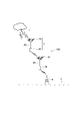
- 2A and 2B are diagrams showing a flying portion, a conductor cable, and a weight that constitute the flying object shown in FIG. 1
- FIG. 4 is a flow chart showing a processing procedure of a lightning induction method according to the embodiment of the present invention
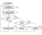
- FIG. 3 is a flow chart showing part of a processing procedure of a flight control unit shown in FIG. 2
- FIG. FIG. 11 is a schematic diagram showing an arrangement example of conductor cables of a lightning-induced system of a modified example
- FIG. 1 is a schematic diagram schematically showing an example in which a lightning induction system according to an embodiment of the present invention induces lightning.
- a lightning induction system 100 shown in FIG. 1 includes a plurality of flying objects 3 .
- FIG. 1 shows an example in which two flying objects 3 are flown between a lightning point 1 of a thundercloud and the ground surface 2 to guide lightning to a lightning target, such as a steel tower 4 .
- the flying object 3 is composed of a flying section 10, a conductor cable 20, and a weight section 30.
- the flight unit 10 is a radio flying object, generally called a drone, and normally flies under the remote control of a drone pilot (not shown) on the ground.
- the flight unit 10 and a remote controller (not shown) operated by a drone pilot are wirelessly connected.
- the two flight sections 10 may be remotely controlled by one drone pilot or may be remotely controlled by another drone pilot.
- the flying unit 10 does not have to be a wireless flying object.
- a manned flying object such as a helicopter may be used. In this case, there is no need for a remote-controlled drone pilot.
- One end of the conductor cable 20 is locked to the flying section 10 and guides downward the energy of lightning striking the flying section 10 .
- the current of lightning reaches several hundred thousand amperes at the maximum, and the duration of occurrence is about 1/10,000 second to about 1/1,000 second.
- the length of the conductor cable 20 is, for example, about 100 m.
- the weight part 30 is locked to the other end of the conductor cable 20 .
- the weight section 30 applies tension in the vertical downward direction to the conductor cable 20 and stabilizes the attitude of the flying section 10 and the conductor cable 20 .
- a low-impedance lightning induction path is configured between the lightning point 1 and the lightning target (in this example, the steel tower 4). Since the lightning induction path is formed by the path with the lowest impedance, there may be a predetermined gap between the upper weight section 30 and the lower flying section 10 .
- the lightning induction system 100 is a lightning induction system that includes a plurality of flying objects 3 that fly between the lightning point 1 in the sky that generates lightning and the ground surface 2,
- the flying object 3 includes a flying portion 10 that generates lift and propulsion, a conductor cable 20 of a predetermined length that is engaged with the flying portion 10 and extended downward, and a weight portion that is connected to the lower end of the conductor cable 20. 30.
- the length of the conductor cable 20 can be shortened, and the lightning induction system 100 that can reduce the accident risk can be provided.
- the conductor cable 20 can be shortened, the load on the drone can be reduced, and the risk of entanglement of the conductor cable 20 and contact with ground equipment can be reduced.
- the conductor cable 20 since there is no need to connect the lightning target and the conductor cable 20, it is possible to easily use a facility high above the ground as a lightning target. Therefore, lightning can be guided more safely.
- FIG. 2 is a diagram showing the flying section 10, the conductor cable 20, and the weight section 30, which constitute the aircraft 3. As shown in FIG.
- the flying part 10 may be arranged and configured inside the Faraday cage 11 .
- the flying part 10 in this case is arranged in a Faraday cage 11, for example a spherical cage.
- the Faraday cage 11 is a space surrounded by conductors, or a conductor cage or container used to create such a space. Electric lines of force cannot penetrate the interior surrounded by conductors, so the external electric field is blocked and all internal potentials are equal.
- the flying part 10 is fixed by a single post 12 extending downward from the inside of the zenith of the Faraday cage 11 .
- the flying part 10 is fixed inside the Faraday cage 11 with a predetermined space therebetween so as not to hinder the flight.
- the flying part 10 and the Faraday cage 11 are connected at one point. Therefore, the flying part 10 is not affected by lightning energy (lightning strike). Alternatively, the effects of lightning strikes can be suppressed.
- the energy of lightning striking the Faraday cage 11 is discharged to the Faraday cage 11 of another flying object 3 via the conductor cable 20 and weight 30 .
- the flight section 10 includes a flight control section 13.
- the flight control unit 13 receives operation signals from the drone pilot and controls generation of lift and propulsion force of the flight unit 10 .
- the flight control unit 13 also has a function of measuring its own altitude.
- the flight control unit 13 can be realized by a computer consisting of ROM, RAM, CPU, etc., for example. In that case, the content of the processing is described by the program.
- the weight section 30 may include an altitude detection section 31 .
- the altitude detection unit 31 and the flight control unit 13 may measure altitude using either an altimeter using a pressure sensor or GPS.
- description of a power supply for operating the altitude detection unit 31 is omitted.
- FIG. 3 is a flow chart showing a processing procedure of a lightning induction method executed using the lightning induction system 100 according to the embodiment of the present invention. A lightning induction method will be described with reference to FIG.
- An administrator using the lightning induction system 100 first secures an area to be protected from lightning (lightning induction area).
- the length of the conductor cable 20 is calculated (step S1).
- the calculation may be performed by a control unit (not shown) that controls the lightning induction system 100, or may be performed by an administrator.
- Target coordinates are set in three dimensions.
- Flight control may be performed by a drone pilot or may be automatically controlled.
- the altitude detection unit 31 of the first flight unit 10 flying in the sky and the flight control unit 13 of the second flight unit 10 flying below may be linked. That is, the drone pilot operates only the first flight section 10 . Then, the second flying part 10 follows the weight part 30 locked to the first flying part 10 and flies like parent and child (marching) of spot-billed ducks.
- FIG. 4 is a flowchart showing part of the processing procedure of the flight control unit 13.
- FIG. An example of flight control for flying a plurality of aircraft 3 will be described with reference to FIG.
- the flight control unit 13 (hereafter, flight control unit 13 2 ) of the second flight unit 10 detects the altitude detection unit 31 ( Thereafter, altitude information detected by the altitude detection unit 31 1 ) is received (step S10).
- the suffix “ 1 ” represents the first flight section 10 1
- the suffix “ 2 ” represents each functional component of the second flight section 10 2 .
- the flight control unit 132 calculates the altitude difference between itself and the weight 30-1 based on its own altitude information and the altitude information received from the weight 30-1 of the first flight unit 10-1 (step S11).
- step S12 the flight control unit 132 determines whether or not the altitude difference is appropriate.
- step S12 If the altitude difference is determined to be appropriate (suitable in step S12), the flight control unit 132 maintains the current lift (step S13).
- step S12 If the altitude difference is determined to be inappropriate (improper in step S12), the flight control unit 132 continues to determine whether the altitude difference is positive (step S14).
- a plus altitude difference means that the second flight portion 10-2 is close to the weight portion 30-1.
- step S14 If the altitude difference is positive (YES in step S14), the flight control unit 132 reduces lift (step S15). If the altitude difference is negative (NO in step S14), the flight control unit 132 increases lift ( step S16).
- weight section 30-1 engaged with first flight section 10-1 has altitude detection section 31-1 that measures altitude and transmits the measured altitude information to other flight sections 10-2 .
- the lightning induction system 100 is configured such that the second flight section 10-2 receives altitude information and includes a flight control section 13-2 that controls lift so as to maintain a predetermined altitude difference with the weight section 30-1. You may Thereby, operation of the lightning induction system 100 can be facilitated.
- FIG. 5 is a schematic diagram showing how the lightning induction system 100 of the modified example guides lightning in the horizontal direction.
- both ends of the conductor cable 20 are connected to the flight section 10 .
- the notation of the flight section 10 is omitted.
- the conductor cables 20 1 and 20 2 can be horizontally arranged with predetermined intervals d 1 and d 2 . According to a variant, it is possible to direct lightning from the lightning point 1 which is farther than the original lightning induction area of the steel tower 4 .
- the horizontal distance from the lightning point 1 to, for example, the steel tower 4 (lightning target) can be increased as shown in the following equation.
- l 1 is the length of the conductor cable 20 - 1 and l 2 is the length of the conductor cable 20 - 2 .
- the relay conductor cable 20 is provided between the lightning capture flying object 31 provided with the conductor cable 201 and the lightning target (for example, the steel tower 4 ).
- the lightning target for example, the steel tower 4
- flying one or more flying objects 3 so as to form a path with low impedance via each conductor cable 20, it is possible to shorten the conductor length of the conductor cable 20, and the length of the conductor cable 20 is reduced. It is possible to reduce the load due to height and the risk of contact with ground objects other than lightning targets.
- the number of flying objects 3 may be n (n is a natural number).
- the shape of the Faraday cage 11 is not limited to a sphere. Also, the Faraday cage 11 is not essential.
- Lightning Induction System 1: lightning point 2: ground surface 3: flying object 4: lightning target (steel tower) 10: Flight Unit 11: Faraday Cage 12: Strut 13: Flight Control Unit 20: Conductor Cable 30: Weight Unit 31: Altitude Detection Unit 100: Lightning Induction System
Landscapes
- Engineering & Computer Science (AREA)
- Aviation & Aerospace Engineering (AREA)
- Mechanical Engineering (AREA)
- Remote Sensing (AREA)
- Elimination Of Static Electricity (AREA)
Abstract
Description
図2は、飛行体3を構成する飛行部10、導体ケーブル20、及び錘部30のそれぞれを示す図である。
図3は、本発明の実施形態に係る誘雷システム100を用いて実行する誘雷方法の処理手順を示すフローチャートである。図3を参照して誘雷方法について説明する。
なお、錘部30を飛行部10で構成する変形例も考えられる。変形例の誘雷システム100によれば、雷を水平方向に誘導することができる。

2:地表
3:飛行体
4:着雷目標物(鉄塔)
10:飛行部
11:ファラデーケージ
12:支柱
13:飛行制御部
20:導体ケーブル
30:錘部
31:高度検出部
100:誘雷システム
Claims (5)
- 雷を発生する上空の発雷点と地表との間を飛行する複数の飛行体を備える誘雷システムであって、
前記飛行体は、
揚力及び推進力を発生させる飛行部と、
前記飛行部に係止され下方に延伸させられる所定の長さの導体ケーブルと、
前記導体ケーブルの下端に接続される錘部と
を備える誘雷システム。 - 前記飛行部は、ファラデーケージの中に配置される
請求項1に記載の誘雷システム。 - 前記ファラデーケージの形状は球であり、
前記飛行部は、前記球の天頂内側から下方向に延伸される支柱で固定されている
請求項2に記載の誘雷システム。 - 第1の前記飛行部に係止された前記錘部は、高度を計測し、該計測した高度情報を他の前記飛行部に送信する高度検出部を備え、
第2の前記飛行部は、前記高度情報を受信し、前記錘部と所定の高度差を維持するように前記揚力を制御する飛行制御部を備える
請求項1乃至3の何れかに記載の誘雷システム。 - 雷を発生する上空の発雷点から地表に落雷する雷エネルギーを複数の飛行体を介して前記地表に誘導する誘雷方法であって、
前記飛行体は、
揚力及び推進力を発生させる飛行部と、
前記飛行部に係止され下方に延伸させられる所定の長さの導体ケーブルと、
前記導体ケーブルの下端に接続される錘部と
を備える誘雷方法。
Priority Applications (3)
| Application Number | Priority Date | Filing Date | Title |
|---|---|---|---|
| US18/279,417 US12409948B2 (en) | 2021-03-03 | 2021-03-03 | Lightning induction system and method therefor |
| PCT/JP2021/008121 WO2022185441A1 (ja) | 2021-03-03 | 2021-03-03 | 誘雷システム及びその方法 |
| JP2023503255A JP7534694B2 (ja) | 2021-03-03 | 2021-03-03 | 誘雷システム及びその方法 |
Applications Claiming Priority (1)
| Application Number | Priority Date | Filing Date | Title |
|---|---|---|---|
| PCT/JP2021/008121 WO2022185441A1 (ja) | 2021-03-03 | 2021-03-03 | 誘雷システム及びその方法 |
Publications (1)
| Publication Number | Publication Date |
|---|---|
| WO2022185441A1 true WO2022185441A1 (ja) | 2022-09-09 |
Family
ID=83155182
Family Applications (1)
| Application Number | Title | Priority Date | Filing Date |
|---|---|---|---|
| PCT/JP2021/008121 Ceased WO2022185441A1 (ja) | 2021-03-03 | 2021-03-03 | 誘雷システム及びその方法 |
Country Status (3)
| Country | Link |
|---|---|
| US (1) | US12409948B2 (ja) |
| JP (1) | JP7534694B2 (ja) |
| WO (1) | WO2022185441A1 (ja) |
Cited By (2)
| Publication number | Priority date | Publication date | Assignee | Title |
|---|---|---|---|---|
| WO2025169296A1 (ja) * | 2024-02-06 | 2025-08-14 | Ntt株式会社 | ドローン用ケージおよびケージ保護方法 |
| WO2026062748A1 (ja) * | 2024-09-17 | 2026-03-26 | Ntt株式会社 | 防護システム |
Families Citing this family (2)
| Publication number | Priority date | Publication date | Assignee | Title |
|---|---|---|---|---|
| JP7714302B2 (ja) * | 2020-11-13 | 2025-07-29 | Ntt株式会社 | 飛行体の耐雷撃構造 |
| CN118475231B (zh) * | 2024-07-12 | 2025-04-04 | 北京智芯微电子科技有限公司 | 隔离电容器件及其制备方法、多通道隔离芯片以及晶圆 |
Citations (4)
| Publication number | Priority date | Publication date | Assignee | Title |
|---|---|---|---|---|
| US20100212925A1 (en) * | 2009-02-24 | 2010-08-26 | Alliant Techsystems Inc. | Lightning directing system |
| WO2015049798A1 (ja) * | 2013-10-04 | 2015-04-09 | 株式会社日立製作所 | 軽量小型飛行体 |
| KR20170033625A (ko) * | 2015-09-17 | 2017-03-27 | 엘지전자 주식회사 | 드론 |
| CN107539466A (zh) * | 2016-06-29 | 2018-01-05 | 北京末元科技有限公司 | 一种用于全景拍摄的无人机 |
Family Cites Families (2)
| Publication number | Priority date | Publication date | Assignee | Title |
|---|---|---|---|---|
| JP2017182959A (ja) * | 2016-03-29 | 2017-10-05 | 日本電気株式会社 | 無人航空機、無人航空機制御システム、無人航空機制御方法 |
| DE102022002226A1 (de) * | 2021-08-21 | 2023-06-15 | Kastriot Merlaku | Leucht-System, das ein Stadion beleuchten soll |
-
2021
- 2021-03-03 JP JP2023503255A patent/JP7534694B2/ja active Active
- 2021-03-03 US US18/279,417 patent/US12409948B2/en active Active
- 2021-03-03 WO PCT/JP2021/008121 patent/WO2022185441A1/ja not_active Ceased
Patent Citations (4)
| Publication number | Priority date | Publication date | Assignee | Title |
|---|---|---|---|---|
| US20100212925A1 (en) * | 2009-02-24 | 2010-08-26 | Alliant Techsystems Inc. | Lightning directing system |
| WO2015049798A1 (ja) * | 2013-10-04 | 2015-04-09 | 株式会社日立製作所 | 軽量小型飛行体 |
| KR20170033625A (ko) * | 2015-09-17 | 2017-03-27 | 엘지전자 주식회사 | 드론 |
| CN107539466A (zh) * | 2016-06-29 | 2018-01-05 | 北京末元科技有限公司 | 一种用于全景拍摄的无人机 |
Cited By (2)
| Publication number | Priority date | Publication date | Assignee | Title |
|---|---|---|---|---|
| WO2025169296A1 (ja) * | 2024-02-06 | 2025-08-14 | Ntt株式会社 | ドローン用ケージおよびケージ保護方法 |
| WO2026062748A1 (ja) * | 2024-09-17 | 2026-03-26 | Ntt株式会社 | 防護システム |
Also Published As
| Publication number | Publication date |
|---|---|
| US20240182168A1 (en) | 2024-06-06 |
| JPWO2022185441A1 (ja) | 2022-09-09 |
| US12409948B2 (en) | 2025-09-09 |
| JP7534694B2 (ja) | 2024-08-15 |
Similar Documents
| Publication | Publication Date | Title |
|---|---|---|
| WO2022185441A1 (ja) | 誘雷システム及びその方法 | |
| US12344394B2 (en) | Lightning strike resistant structure of flying object | |
| JP2020091240A (ja) | 風力発電装置のブレード内引き下げ導線導通検査方法 | |
| CA2935731A1 (en) | Towed active airborne platform for determining measurement data | |
| JP6819259B2 (ja) | 移動式クレーン | |
| KR102302568B1 (ko) | 송전 구조물 감시용 무인항공기의 비행경로 설정 장치 및 그 방법 | |
| WO2023135680A1 (ja) | 飛行体の給電装置とその方法 | |
| DE69310520T2 (de) | Blitzschutz vorrichtung | |
| CN116639286A (zh) | 一种无人机高空投放系统及利用其进行监测的方法 | |
| US10641891B2 (en) | Solar enabled aerial deployed radio antenna system | |
| US20250353610A1 (en) | Flying object with faraday cage | |
| Adyatma et al. | Tropical lightning damage on commercial aircraft | |
| Nam et al. | High Altitude Aerial Platform" Mothership" Project Vision and Progress | |
| JP2025112890A (ja) | 点検装置及び点検方法 | |
| WO2024147141A1 (en) | Bird deflector aerial deployment device and method | |
| Miś | Experiment-based risk evaluation for a stratospheric VLF antenna system | |
| Malinga et al. | Lightning field behavior around grounded airborne systems | |
| Parus et al. | Drone-Triggered Lightning: The Concept and Results of Initial Laboratory Testing | |
| CN106774417A (zh) | 一种新型的无人机巡检高耸结构时的飞行区域控制方法 | |
| JP2022139231A (ja) | 導線の導通確認方法 | |
| US20220033101A1 (en) | Lightweight Bracket for Storm Hardening of Aircraft Components | |
| Bellavia et al. | Electromagnetic compatibility tests for multirotor UAS | |
| RU162643U1 (ru) | Устройство для размещения оборудования различного функционального назначения в надземном пространстве | |
| US20140263830A1 (en) | Launch lightning risk mitigation system and method | |
| RU2319319C1 (ru) | Способ формирования беспроводных сетей передачи информации и высотная винтокрылая платформа для его реализации |
Legal Events
| Date | Code | Title | Description |
|---|---|---|---|
| 121 | Ep: the epo has been informed by wipo that ep was designated in this application |
Ref document number: 21929017 Country of ref document: EP Kind code of ref document: A1 |
|
| WWE | Wipo information: entry into national phase |
Ref document number: 2023503255 Country of ref document: JP |
|
| WWE | Wipo information: entry into national phase |
Ref document number: 18279417 Country of ref document: US |
|
| NENP | Non-entry into the national phase |
Ref country code: DE |
|
| 122 | Ep: pct application non-entry in european phase |
Ref document number: 21929017 Country of ref document: EP Kind code of ref document: A1 |
|
| WWG | Wipo information: grant in national office |
Ref document number: 18279417 Country of ref document: US |