WO2022181088A1 - バーリング加工方法、バーリング加工用金型、バーリング加工装置およびバーリング加工品 - Google Patents
バーリング加工方法、バーリング加工用金型、バーリング加工装置およびバーリング加工品 Download PDFInfo
- Publication number
- WO2022181088A1 WO2022181088A1 PCT/JP2022/000722 JP2022000722W WO2022181088A1 WO 2022181088 A1 WO2022181088 A1 WO 2022181088A1 JP 2022000722 W JP2022000722 W JP 2022000722W WO 2022181088 A1 WO2022181088 A1 WO 2022181088A1
- Authority
- WO
- WIPO (PCT)
- Prior art keywords
- die
- burring
- hole
- support surface
- punch
- Prior art date
- Legal status (The legal status is an assumption and is not a legal conclusion. Google has not performed a legal analysis and makes no representation as to the accuracy of the status listed.)
- Ceased
Links
Images


Classifications
-
- B—PERFORMING OPERATIONS; TRANSPORTING
- B21—MECHANICAL METAL-WORKING WITHOUT ESSENTIALLY REMOVING MATERIAL; PUNCHING METAL
- B21D—WORKING OR PROCESSING OF SHEET METAL OR METAL TUBES, RODS OR PROFILES WITHOUT ESSENTIALLY REMOVING MATERIAL; PUNCHING METAL
- B21D19/00—Flanging or other edge treatment, e.g. of tubes
- B21D19/005—Edge deburring or smoothing
-
- B—PERFORMING OPERATIONS; TRANSPORTING
- B21—MECHANICAL METAL-WORKING WITHOUT ESSENTIALLY REMOVING MATERIAL; PUNCHING METAL
- B21D—WORKING OR PROCESSING OF SHEET METAL OR METAL TUBES, RODS OR PROFILES WITHOUT ESSENTIALLY REMOVING MATERIAL; PUNCHING METAL
- B21D19/00—Flanging or other edge treatment, e.g. of tubes
- B21D19/08—Flanging or other edge treatment, e.g. of tubes by single or successive action of pressing tools, e.g. vice jaws
- B21D19/088—Flanging or other edge treatment, e.g. of tubes by single or successive action of pressing tools, e.g. vice jaws for flanging holes
-
- B—PERFORMING OPERATIONS; TRANSPORTING
- B21—MECHANICAL METAL-WORKING WITHOUT ESSENTIALLY REMOVING MATERIAL; PUNCHING METAL
- B21D—WORKING OR PROCESSING OF SHEET METAL OR METAL TUBES, RODS OR PROFILES WITHOUT ESSENTIALLY REMOVING MATERIAL; PUNCHING METAL
- B21D28/00—Shaping by press-cutting; Perforating
- B21D28/02—Punching blanks or articles with or without obtaining scrap; Notching
- B21D28/16—Shoulder or burr prevention, e.g. fine-blanking
-
- B—PERFORMING OPERATIONS; TRANSPORTING
- B21—MECHANICAL METAL-WORKING WITHOUT ESSENTIALLY REMOVING MATERIAL; PUNCHING METAL
- B21D—WORKING OR PROCESSING OF SHEET METAL OR METAL TUBES, RODS OR PROFILES WITHOUT ESSENTIALLY REMOVING MATERIAL; PUNCHING METAL
- B21D37/00—Tools as parts of machines covered by this subclass
- B21D37/08—Dies with different parts for several steps in a process
-
- B—PERFORMING OPERATIONS; TRANSPORTING
- B21—MECHANICAL METAL-WORKING WITHOUT ESSENTIALLY REMOVING MATERIAL; PUNCHING METAL
- B21D—WORKING OR PROCESSING OF SHEET METAL OR METAL TUBES, RODS OR PROFILES WITHOUT ESSENTIALLY REMOVING MATERIAL; PUNCHING METAL
- B21D53/00—Making other particular articles
- B21D53/88—Making other particular articles other parts for vehicles, e.g. cowlings, mudguards
Definitions
- the present invention relates to a burring method, a burring die, a burring apparatus, and a burred product.
- a technique for forming a substantially cylindrical burred part by burring the pilot holes provided in the metal parts and metal plates that are the workpieces.
- the periphery of the pilot hole is extruded and part of it is formed into a cylindrical shape to form a burred part.
- a cylindrical flange (rising portion) is connected to a portion of a metal part or metal plate on the peripheral portion thereof via a curved portion. This burring portion is required to have fatigue properties and dimensional accuracy.
- Patent Document 1 compressive stress is applied to the end of the burred portion by coining to relax the tensile residual stress, and localized stress is applied to the inner surface of the bend of the curved portion that constitutes the root of the burred portion.
- Techniques for suppressing wrinkles and cracks that occur on the inner surface due to the concentration of compressive stress are disclosed.
- a burring technique a stepwise forming method as described in Patent Document 2 has also been proposed.
- the burring processed part is also used for vehicle suspension parts.
- vehicle underbody parts such as lower arms and trailing arms are required to have fatigue properties. If a fatigue load is applied to a part in which tensile residual stress is generated inside the curved portion of the burred portion, the burred portion may be deformed.
- a minute crack internal bending crack
- a shape change may be required depending on the burring method.
- the present invention has been made in view of the above problems, and provides a burring method, a burring die, a burring apparatus, and a burred product that can suppress the occurrence of cracks in the curved portion of the burring portion. intended to
- a burring method comprises: a first die with a first die hole and a first support surface perpendicular to the axis of the first die hole; a second die hole and a second support surface perpendicular to the axis of the second die hole a second die comprising a holder comprising a third support surface facing the first support surface and the second support surface, and sandwiching a metal component between the first die and the second die; a punch having a shaft portion and movable along the axis of the first die hole and the axis of the second die hole; the first support surface, the second support surface and the third support surface are arranged parallel to each other; Using a burring mold in which the diameter of the second die hole is smaller than the diameter of the first die hole and the outer diameter of the second support surface is smaller than the diameter of the first die hole, A method for forming a burring portion including a rising portion and a curved portion in the metal part having a pilot hole formed therein, While enlarg
- a main molding step of molding so that a part of the third range on the inner diameter side of the preformed portion than the second range becomes part of the rising portion and the curved portion; including The outer diameter of the curved portion is smaller than the outer diameter of the preformed portion, and In a cross-sectional view parallel to the first direction and passing through the center of the pilot hole, the maximum curvature radius of the curved portion is smaller than the minimum curvature radius of the preformed portion,
- the metal component is sandwiched between the first support surface of the first die and the third support surface of the holder, and the punch is directed in the first direction and relatively moved with respect to the first die.
- the second die is moved in the second direction relative to the holder to move the punch and the third support surface.
- a burring method includes: a first die having a first die hole and a first support surface perpendicular to the axis of the first die hole; a first holder having a first holder support surface facing the first support surface and arranged in parallel with the first support surface, and sandwiching a metal component between the first die and the first holder; a set of preforming dies comprising a first punch having a first shank and movable along the axis of the first die hole; a second die comprising a second die hole and a second support surface perpendicular to the axis of the second die hole; a second holder having a second holder support surface facing the second support surface and arranged in parallel with the second support surface, the second holder sandwiching the metal component between the second die; a second punch having a second shank and movable along the axis of the second die hole; and Using a burring mold containing A method for forming a burring portion including a rising portion and
- a main molding step of molding so that a part of the third range on the inner diameter side of the preformed portion than the second range becomes part of the rising portion and the curved portion; including The outer diameter of the curved portion is smaller than the outer diameter of the preformed portion, and In a cross-sectional view parallel to the first direction and passing through the center of the pilot hole, the maximum curvature radius of the curved portion is smaller than the minimum curvature radius of the preformed portion,
- the metal part is sandwiched between the first support surface of the first die and the first holder support surface of the first holder, and the first punch is directed in the first direction to the first die.
- the preforming portion is formed between the first punch and the first die by relatively moving the first punch and inserting the first punch into the first die hole, Separating the metal part in which the preformed portion is formed from the preformed mold, Next, the metal component having the preformed portion formed thereon is placed on the second holder support surface of the second holder so that the metal component having the preformed portion formed faces the first direction.
- the diameter of the second die hole is less than or equal to the diameter of the first die hole, The following formula 2 is satisfied, where t is the height of the edge of the pilot hole of the metal part, and h is the height of the outer surface of the curved portion in the first direction. 0.2 ⁇ h/t ⁇ 0.6. . .
- Equation 5 Equation 5
- the second punch may be inserted into the enlarged pilot hole in the first direction, and then the second die may be moved in the second direction relative to the second holder. .
- the second die may be moved in the second direction relative to the second holder, and then the second punch may be inserted in the expanded hole in the first direction. .
- the diameter of the first shaft portion of the first punch may be smaller than the diameter of the second shaft portion of the second punch.
- the initial contact position between the preforming portion and the second die is a portion having the curvature of the second die shoulder of the second die hole in a cross-sectional view parallel to the first direction and passing through the center of the pilot hole. from the inner wall side of the second die hole to 7/8 of the surface length.
- a tensile strength of the metal component may be 780 MPa or more.
- the following formula 4 may be satisfied, where t is the height of the edge of the prepared hole of the metal component, and tb is the thickness of the opening-side end of the rising portion. tb/t ⁇ 0.9 Equation 4 (10)
- a pilot hole forming step of forming the pilot hole in the metal component may be further included before the preforming step.
- a mold for burring for forming a burring portion including a raised portion and a curved portion in a metal part having a pilot hole formed therein, a first die with a first die hole and a first support surface perpendicular to the axis of the first die hole; a second die hole and a second support surface perpendicular to the axis of the second die hole a second die comprising a holder comprising a third support surface facing the first support surface and the second support surface, and sandwiching a metal component between the first die and the second die; a punch provided with a shaft portion and movable along the axis of the first die hole and the axis of the second die hole; and the first support surface, the second support surface and the third support surface are arranged parallel to each other;
- the diameter of the second die hole is smaller than the diameter of the first die hole, and the outer diameter of the second support surface is smaller than the diameter of the first die hole.
- a burring device according to one aspect of the present invention, The burring die according to (11) above is provided, and a drive mechanism capable of relatively moving the first die, the second die, the holder, and the punch relative to each other is provided.
- a burred product according to one aspect of the present invention is A burred product having a burred portion including a rising portion and a curved portion and a peripheral region surrounding the curved portion,
- R radius of curvature of the outer surface of the curved portion
- a distance R is separated in a direction perpendicular to the axis, and the rising portion is formed from the surface on the side toward the axis.
- Hva be the hardness of the burred product at a position a separated by 0.2 mm in the parallel direction, From the R stop of the curved portion to the peripheral region side in the direction perpendicular to the axis by three times R, and from the surface on which the rising portion is formed in the peripheral region in the direction parallel to the axis
- the peripheral region has an indentation
- the height of the rising portion is Us
- the indentation is 0.5 ⁇ Us or more from the R stop of the curved portion and 20 ⁇ Us
- the maximum height or depth of the indentation in the direction parallel to the axis is more than ts/20 and ts/ characterized by being less than 3.
- the burred product according to (13) above is The Hva is the average hardness measured in the cross-sectional area defined by a square centered at the position a and having a side length of 1/6 of the thickness of the burred product.
- the Hvb is the average hardness measured in the area on the cross section defined by a square whose center is the position b and whose side length is 1/6 of the thickness of the burred product.
- the present invention it is possible to provide a burring method, a burring mold, a burring device, and a burred product that can suppress the occurrence of cracks in the burred portion.
- FIG. 4 is a schematic cross-sectional view showing the state of compressive strain and internal bending cracks in the curved portion of the burring portion.
- FIG. 4 is a schematic cross-sectional view for explaining a state in which a workpiece (metal part) rises in the forming process of burring;
- 3A to 3C are schematic plan views for explaining the forming process of conventional burring.
- FIGS. 4A to 4C are schematic sectional views for explaining the forming process of burring in FIGS. 3A to 3C, respectively.
- 1 is a schematic cross-sectional view for explaining a burring die according to a first embodiment;
- FIG. FIG. 4 is a schematic cross-sectional view for explaining a state in which a metal part is sandwiched between burring dies;
- FIG. 4 is a schematic cross-sectional view for explaining a burring die after preforming and a metal part having a preformed portion formed thereon;
- FIG. 3 is a schematic cross-sectional view for explaining a burring mold and a burred product after final molding;
- 9A to 9C are schematic plan views for explaining the forming process of the burring method according to the first embodiment.
- FIGS. 10A to 10C are schematic cross-sectional views for explaining the forming process of burring in the states of FIGS. 9A to 9C, respectively.
- FIG. 5 is a schematic cross-sectional view for explaining a preforming mold for a burring mold according to a second embodiment;
- FIG. 5 is a schematic cross-sectional view for explaining a preforming mold for a burring mold according to a second embodiment;
- FIG. 10 is a schematic cross-sectional view for explaining a main molding die of a burring die according to a second embodiment
- FIG. 10 is a schematic cross-sectional view for explaining a preforming mold after preforming and a metal component having a preforming portion formed thereon according to the second embodiment
- FIG. 11 is a schematic cross-sectional view for explaining a state in which a metal part having a preformed portion formed thereon is placed on the main forming mold according to the second embodiment.
- FIG. 15 is a schematic cross-sectional view for explaining a state in which a second punch is inserted into the diameter-expanded pilot hole from the state of FIG. 14 in the main molding die according to the second embodiment.
- FIG. 10 is a schematic cross-sectional view for explaining a main molding die of a burring die according to a second embodiment
- FIG. 10 is a schematic cross-sectional view for explaining a preforming mold after preforming and a metal component having a preforming portion formed thereon according to the second embodiment
- FIG. 16 is a schematic cross-sectional view for explaining a state in which the second die is relatively moved with respect to the second holder from the state of FIG. 15 and the burring portion is formed in the main molding die according to the second embodiment; be.
- Schematic cross-sectional view for explaining a state in which the second die is moved relative to the second holder to deform the preforming portion from the state of FIG. 14 in the main molding die according to the second embodiment. is.
- FIG. 11 is a schematic cross-sectional view for explaining a burred product according to a third embodiment
- FIG. 10 is a schematic cross-sectional view for explaining indentations that the burred product according to the third embodiment has;
- FIG. 1 is a schematic cross-sectional view showing the state of compressive strain and internal bending cracks in a curved portion of a burred portion.
- FIG. 1 shows a state in which the burred product 10 is viewed in cross section along a plane that passes through the axis cb of the burred portion 11 and is parallel to the axis cb. showing.
- a burred portion 11 of a burred product 10 has a curved portion 12 and a raised portion 13 .
- the outer surface 12a of the curved portion 12 is subjected to compressive strain in the direction of the arrow in the figure, and bending inner cracks CR are generated starting from irregularities caused by this compressive strain.
- the present inventors have found that when the radius of curvature of the curved portion of the burring portion is extremely small relative to the plate thickness of the work material and the work material is a high-strength material, internal bending cracks may occur. It has been found that this internal bending crack is caused by the portion where the material rises on the inner surface of the curved portion during the molding process.
- FIG. 2 shows a schematic cross-sectional view for explaining the state in which the workpiece rises during the forming process of burring.
- FIG. 2 is a diagram showing a state in which the work material M is sandwiched between the die 20 and the holder 30 and the work material M is deformed by the punch 40 to form the curved portion 12 in the forming process of burring. be.
- the radius of curvature of the die shoulder 21 corresponding to the radius of curvature of the curved portion of the burring portion is small, the outer surface 12a of the curved portion 12 in contact with the die shoulder 21, especially in the early stages of the forming process. A bulging portion BP is generated at the .
- the burring method includes a first die having a first die hole and a first support surface perpendicular to the axis of the first die hole, a second die hole and the axis of the second die hole a second die with a second support surface perpendicular to the metal part; and a third support surface opposite the first and second support surfaces; a clamping holder; and a punch having a shank and movable along the axis of the first die hole and the axis of the second die hole; A burring die, wherein the support surfaces are arranged parallel to each other, the diameter of the second die hole is smaller than the diameter of the first die hole, and the outer diameter of the second support surface is smaller than the diameter of the first die hole.
- the outer diameter of the curved portion is smaller than the outer diameter of the preformed portion, and the maximum curvature radius of the curved portion in a cross-sectional view parallel to the first direction and passing through the center of the pilot hole is smaller than the minimum radius of curvature of the preform, clamping the metal part between the first support surface of the first die and the third support surface of the holder, and directing the punch in the first direction against the first die
- a preformed portion is formed between the punch and the first die, and the metal part is sandwiched between the first support surface and the third support surface.
- the second die is moved in the second direction relative to the holder, and a part of the second die is inserted between the punch and the first die, whereby the second die, the punch and the holder
- the burring part is formed between and the difference between the radius of the first die hole and the radius of the second die hole is U
- the diameter of the punch shaft is P
- the diameter of the pilot hole of the metal part is A
- the following formula 1 is satisfied
- the following formula 2 is satisfied when t is the height of the edge of the pilot hole of the metal part and h is the height of the outer surface of the curved part in the first direction. .
- 0.5 ⁇ (P ⁇ A)/2 ⁇ U ⁇ 20 ⁇ (P ⁇ A)/2 . . . formula 1 0.2 ⁇ h/t ⁇ 0.6. . . formula 2
- FIGS. 3(A) to 3(C) are schematic plan views for explaining the forming process of conventional burring, and are plan views from a direction intersecting the surface of the metal part 1.
- FIG. 3A shows a metal part 1 with a pilot hole 2.
- FIG. 3B shows a state in which the periphery of the pilot hole 2 is deformed and the diameter of the pilot hole 2 is expanded.
- (C) of FIG. 3 shows a burred product 100 that has been burred.
- 4A to 4C are schematic cross-sectional views for explaining the forming process of the burring process in FIGS.
- the diameter of the pilot hole 2 provided in the metal part 1 is expanded and a portion of the metal part 1 is bent to form the rising portion 120 and the curved portion 130.
- a burring portion 110 including is molded.
- minute cracks internal bending cracks
- the burring method according to this embodiment will be described below.
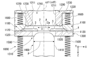
- a burring method using a burring die 1000 as shown in FIG. 5 will be described.
- the burring die used in this embodiment as shown in FIG. and a second die 1200 having a second die hole 1210 and a second support surface 1220 perpendicular to the axis cd2 of the second die hole 1210, and a first support surface 1120 and a second support surface 1220 facing each other
- a holder 1300 having three supporting surfaces 1320 and sandwiching the metal part 1 between the first die 1100 and the second die 1200, and a shaft portion 1410, the axis cd1 of the first die hole 1110 and the second die hole 1210 and a punch 1400 movably provided along the axis cd2 of.
- the inner wall surface 1111 of the first die hole 1110 of the first die 1100 and the first support surface 1120 are connected by the first die shoulder surface 1130 .
- the inner wall surface 1211 of the second die hole 1210 of the second die 1200 and the second support surface 1220 are connected by the second die shoulder surface 1230 .
- the second support surface 1220 is connected to the die hole side surface 1240 .
- the die hole side surface 1240 is located on the outer peripheral side of the inner wall surface 1211 of the second die hole 1210 .
- the outer diameter ro2 of the second support surface 1220 is the diameter of the die hole side surface 1240 in plan view along the axis cd1 of the first die hole 1110 .
- the diameter of the die hole side surface 1240 is the diameter when the shape of the die hole side surface 1240 in plan view along the axis cd2 of the second die hole 1210 is circular.
- the distance between the axis cd2 of the second die hole 1210 and the die hole side surface 1240 is the largest. is doubled as the diameter of the die hole side surface 1240 .
- the second support surface 1220 and the die hole side surface 1240 may be connected via a ridge (not shown), but the width of this ridge may be small.
- the axis cd1 of the first die hole 1110 and the Z-axis are parallel.
- the Z-axis, X-axis and Y-axis in FIG. 5 etc. are orthogonal to each other.
- a substantially cylindrical punch 1400 includes a shaft portion 1410 , and a shaft portion side surface 1411 of the shaft portion 1410 is connected to a top surface 1420 via a punch shoulder surface 1430 .
- the first support surface 1120, the second support surface 1220 and the third support surface 1320 are arranged parallel to each other.
- the top surface 1420 of the punch 1400 may also be arranged parallel to the first support surface 1120 , the second support surface 1220 and the third support surface 1320 .
- the axis cd1 of the first die hole 1110 and the axis cd2 of the second die hole 1210 match.
- the axis (not shown) of the holder hole 1310 of the holder 1300 coincides with the axis cd1 of the first die hole 1110 .
- the axis of the hole is a line passing through the center of the circular shape drawn by the edge of the hole and parallel to the depth direction of the hole.
- the axis (not shown) of the punch 1400 coincides with the axis cd1 of the first die hole 1110 .
- the axis of the punch 1400 is the axis of the substantially cylindrical portion of the punch.
- the diameter rd2 of the second die hole 1210 is smaller than the diameter rd1 of the first die hole 1110, and the outer diameter ro2 of the second support surface 1220 is smaller than the diameter rd1 of the first die hole. .
- the inner wall surface 1111 of the first die hole 1110, the inner wall surface 1211 of the second die hole 1210, and the shaft portion side surface 1411 of the punch 1400 are each circular.
- the die hole side surface 1240 of the second die 1200 and the inner wall surface of the holder hole 1310 of the holder 1300 may be circular or have other shapes. good too.
- the diameter of the inner wall surface 1211 of the second die hole 1210 (diameter of the second die hole 1210) rd2 is larger than the diameter of the side surface 1411 of the punch 1400.
- the diameter of the inner wall surface 1111 of the first die hole 1110 (the diameter of the first die hole 1110 ) rd1 is larger than the diameter of the inner wall surface 1211 of the second die hole 1210 .
- the diameter of the inner wall surface 1111 of the first die hole 1110 is larger than the maximum value of the diameter of the die hole side surface 1240 of the second die 1200.
- the holder 1300 is connected to the spring 1500.
- the spring 1500 may be connected to the pedestal of the mold on the side opposite to the side connected to the holder 1300 .
- the punch 1400 may be connected to the base of the mold on the side opposite to the top surface 1420 side facing the first die 1100 and the second die 1200 side, and may be configured to be movable.
- the first die 1100, the second die 1200 and the holder 1300 may each be connected to a drive section (not shown) and configured to be independently movable.
- FIG. 1 A burring method using the above-described burring mold 1000 will be described below with reference to FIGS. 6 to 10.
- FIG. 1 the metal component 1 which is the workpiece is placed on the third support surface 1320 of the holder 1300 .
- the positive direction of the Z-axis in FIG. As long as the positional relationship between the burring die 1000 and the metal part 1 can be maintained, the axis cd1 of the first die hole 1110 does not have to be parallel to the vertical direction.
- the metal component 1 is sandwiched between the first supporting surface 1120 of the first die 1100 and the third supporting surface 1320 of the holder 1300.
- preforming process preforming is performed.
- the diameter of the pilot hole 2 is expanded, and the edge 2a of the pilot hole 2 is extended in the first direction in the thickness direction of the metal part 1 in the first area 3 around the pilot hole 2 of the metal part 1.
- the first area 3 is molded so as to form a preformed part 4 rising from the metal part 1 in the first direction.
- the first range 3 is a range defined in the metal component 1
- the preformed portion 4 is formed in the metal component 1 by deforming the first range 3 of the metal component 1 .
- the first direction is the negative direction of the Z-axis in FIG. 5 and the like, and the second direction described later is the positive direction of the Z-axis.
- FIG. 9 shows a state in which the metal part 1 provided with the pilot hole 2 is viewed in plan in a direction perpendicular to the surface of the metal part 1 .
- the pilot hole 2 is defined by an edge 2a provided on the metal part 1, and the central axis of the pilot hole 2 is ch.
- 9A to 9C show states viewed from the same direction.
- (A) of FIG. 10 is a cross-sectional view of the metal component 1 of (A) of FIG. 9 taken along a plane passing through the central axis ch. 10A to 10C show states viewed from the same direction.
- FIG. 9(B) is a diagram showing a metal part 1 provided with a preformed portion 4, which is obtained by deforming the metal part 1 of FIG. 9(A).
- FIG. 10 is a cross-sectional view of the metal component 1 of (A) of FIG. 9 taken along a plane through which the central axis ch passes.
- the thickness direction of the metal part 1 is a direction parallel to the central axis ch of the pilot hole 2 .
- the first direction is the direction in which the edge 121 (end on the opening side) of the rising portion 120 of the burred portion 110 faces in the burred product 100 after the main molding process.
- FIG. 7 shows the burring die 1000 and the metal part 1 after preforming.
- the punch 1400 is inserted into the pilot hole 2 to expand the diameter of the pilot hole 2, and the first area 3 is entirely oriented in the first direction. It is molded to form a preformed portion 4 rising from the metal part 1 .
- the holder 1300 is moved in the second direction by the first die 1100 connected to the second die 1200 via the spring 1600, Spring 1500 is compressed.
- the holder 1300 may be moved toward the first die 1100 without being limited to this.
- an example in which the first die 1100 and the second die 1200 are moved at the same time is shown. may be configured.
- the first die 1100 and the second die 1200 are connected by a spring 1600 . Therefore, by moving the second die 1200 relative to the holder 1300 , the first die 1100 also moves relative to the holder 1300 at the same time.
- the preformed portion 4 is deformed in a second direction opposite to the first direction, and the second range 5 on the outer diameter side of the preformed portion 4 is deformed in the first direction.
- FIG. 9C shows a state in which the burred product 100 provided with the burred portion 110 is viewed from the edge portion 121 side of the rising portion 120 of the burred portion 110 along the axis cb of the burred portion. is shown.
- the axis cb of the burring portion and the center axis ch of the pilot hole 2 coincide.
- the preformed portion 4 has a circular shape in plan view in a direction parallel to the central axis ch of the pilot hole 2 .
- the second range 5 is a range included in the preformed portion 4 and on the outer diameter side of the preformed portion 4 .
- the third range 6 is a range included in the preformed portion 4 and is a range closer to the inner diameter side of the preformed portion 4 than the second range 5 .
- One surface of the preforming portion 4 is located on the first direction side of one surface of the first range 3 before preforming in a cross-sectional view along a plane passing through the central axis ch.
- the second die 1200 is directed in the second direction with respect to the holder 1300 while the metal component 1 is sandwiched between the first support surface 1120 and the third support surface 1320.
- a portion of the second die 1200 is inserted between the punch 1400 and the first die 1100 by relative movement, thereby forming the burring portion 110 between the second die 1200 and the punch 1400 and the holder 1300 .
- FIG. 8 shows the burring mold 1000 and the burring product 100 after the main molding.
- the second die 1200 is further moved in the second direction than in the state of FIG. 7, and the spring 1600 is contracted so that the second die 1200 and the holder 1300 are closer than in the state of FIG. It has become.
- first die 1100 and the second die 1200 are connected by the spring 1600 as in the configuration of the burring die according to this embodiment, the first die 1100 and the punch 1400 are moved relative to each other in the preforming step.
- the repulsive force of the spring 1600 In order to move the second die 1200 and the punch 1400 relative to each other in the main forming process, the repulsive force of the spring 1600 must be greater than the repulsive force of the spring 1500 .
- first die 1100, second die 1200, holder 1300 and punch 1400 may be configured to move independently of each other.
- the second die 1200 is inserted between the first die 1100 and the punch 1400, so that the preforming portion 4 is deformed in the second direction. Thereby, the burring portion 110 including the rising portion 120 and the curved portion 130 is formed.
- the outer diameter of the preformed portion 4 is the outer diameter of the preformed portion 4 formed into a circular shape in plan view in a direction parallel to the central axis ch of the pilot hole 2. means outside diameter.
- the outer diameter of the preformed portion 4 can also be rephrased as the circular outer diameter defined by the edge portion 4a of the preformed portion 4 as shown in FIG. 9B.
- the edge portion 4a of the preforming portion 4 is located on the first direction side of the surface at the same height as one surface of the first range 3 before preforming and one surface of the first range 3 before preforming. can be defined as the boundary with the surface that In the burring method according to the present embodiment, indentations (including bending traces), which will be described later, are formed in a range including the edge portion 4a and its vicinity by the preforming step.
- the outer diameter of the curved portion 130 means the outer diameter of the curved portion 130 that is formed into a circular shape in plan view in a direction parallel to the axis cb of the burred portion 110 .
- the outer diameter of the curved portion 130 can also be rephrased as the outer diameter of the circular shape defined by the edge portion 130a of the curved portion 130 as shown in FIG. 9C.
- the edge portion 130a of the curved portion 130 is located on the first direction side of a surface at the same height as one surface of the first range 3 before preforming and one surface of the first range 3 before preforming. It can be defined as the boundary with the surface.
- the radius of curvature of the curved portion 130 is the radius of curvature in a cross-sectional view parallel to the first direction and passing through the center of the pilot hole 2 .
- the first direction coincides with the axis cb of the burring portion 110 .
- the cross section parallel to the first direction and passing through the center of the pilot hole 2 is a cross section parallel to the axis cb of the burring portion 110 and including the axis cb of the burring portion 110 .
- the curved portion 130 may have a constant radius of curvature in this cross-sectional view, or the radius of curvature may vary within the curved portion 130 .
- the maximum curvature radius of the curved portion 130 means the maximum curvature radius in a cross-sectional view parallel to the first direction and passing through the center of the pilot hole 2 among the curvature radii of the curved portion 130 .
- the concave surface that is, the shape of the surface located outside the burring portion 110 corresponds to the shape of the second die shoulder surface 1230 of the second die 1200 .
- the preformed portion 4 may have a constant radius of curvature in a cross-sectional view parallel to the first direction and passing through the center of the pilot hole 2, or the radius of curvature may vary within the preformed portion 4.
- the maximum curvature radius of the preformed portion 4 means the largest curvature radius among the curvature radii of the preformed portion 4 in a cross-sectional view parallel to the first direction and passing through the center of the pilot hole 2 .
- the burring method includes a preforming step and a main forming step, the outer diameter of the curved portion is smaller than the outer diameter of the preformed portion, is parallel to the first direction, and has a prepared hole.
- the maximum curvature radius of the curved portion is smaller than the minimum curvature radius of the preformed portion, so that compressive strain generated in the curved portion can be suppressed, and the curved portion of the burring portion It is possible to suppress the occurrence of cracks in
- U is the difference between the radius of the first die hole 1110 and the radius of the second die hole 1210
- P is the diameter of the shaft of the punch 1400
- P is the diameter of the pilot hole 2 of the metal part 1.
- the diameter is A
- Expression 1 it is possible to form an appropriate preformed portion 4 in the preforming step, and to suppress concentration of compressive strain in the main forming step.
- U is less than 20 ⁇ (PA)/2, the contact area between the second die 1200 and the metal part 1 can be secured, and the bulging portion can be suppressed, thereby suppressing the occurrence of internal bending cracks. .
- the bending internal cracks described above are more likely to occur as h/t is smaller.
- the reason for this is that the smaller the h/t, the smaller the bending radius of the curved portion 130 of the burring portion 110 relative to the plate thickness, the greater the compressive strain of the inner surface layer of the bending, and the more pronounced bulging portion is formed. It's for.
- the effect of the burring method according to the present embodiment is exhibited more remarkably when h/t is less than 0.6.
- h/t is 0.2 or less, the compressive strain in bending becomes excessive, so the formation of bulges cannot be suppressed and cracks in bending may occur. More than 0.2.
- the height of the edge 2a of the pilot hole 2 of the metal part 1 is, in other words, the thickness (board thickness) of the metal part 1 at the edge 2a of the pilot hole 2 .
- the thickness of the metal part 1 at the edge 2a of the prepared hole 2 may be the average value of the values measured at a plurality of locations (eg, 5 locations) using a measuring instrument such as a micrometer or vernier caliper.
- U is the difference between the radius of the first die hole 1110 and the radius of the second die hole 1210
- P is the diameter of the shaft of the punch 1400
- P is the diameter of the pilot hole 2 of the metal part 1.
- the width of the plate thickness t and the behavior of the metal part 1 in the preforming process can be taken into consideration, and the occurrence of internal bending cracks can be further suppressed.
- the burring method according to this embodiment has the advantage that burring can be performed in one process without exchanging dies.
- a steel member having a tensile strength of 780 MPa or more is preferably used as the metal part 1 .
- a steel member having a tensile strength of 980 MPa or more and a steel member having a tensile strength of 1180 MPa or more are more preferably used.
- the tensile strength of the metal part 1 is measured by taking a JIS No. 5 tensile test piece described in JIS Z 2201 from the metal part 1 and performing a tensile test according to JIS Z 2241:2011.
- the thickness of the metal part is preferably 1.8 to 4.2 mm, more preferably 2.0 to 3.9 mm. More preferably, the thickness of the metal part is 2.3-3.2 mm. Desired rigidity and lightness can be ensured by setting the thickness of the metal part within such a range.
- the thickness of metal parts is measured using measuring instruments such as micrometers and vernier calipers. It may be an average value of values obtained by measuring points (for example, 5 points).
- the following Equation 4 may be satisfied.
- the thickness tb may be an average value of values measured at a plurality of locations (for example, 5 locations) using a measuring instrument such as a micrometer or vernier caliper.
- the burring method according to the present embodiment may further include a pre-hole forming step of forming a pre-hole 2 in the metal part 1 before the pre-forming step.
- the first support surface perpendicular to the axis of the first die hole and the first die hole a second die comprising a second die hole and a second support surface perpendicular to the axis of the second die hole; and a third die opposite the first support surface and the second support surface.
- a holder having a supporting surface and holding the metal part between the first die and the second die, and a shaft portion, provided movably along the axis of the first die hole and the axis of the second die hole.
- a burring apparatus including a driving mechanism capable of relatively moving the first die, the second die, the holder, and the punch of the burring die described in the first embodiment. be.
- the burring method according to the present embodiment is a method of forming a burring portion including a raised portion and a curved portion in a metal component having a prepared hole formed therein.
- the edge of the pilot hole is moved relative to the metal part in the first direction in the thickness direction of the metal part in the first range around the hole, and the first range is entirely oriented in the first direction.
- a first die having a first die hole and a first support surface perpendicular to the axis of the first die hole; and a first holder supporting surface arranged parallel to the first die for sandwiching the metal part; a set of preform dies comprising a first punch provided; a second die comprising a second die hole and a second support surface perpendicular to the axis of the second die hole; A second holder having a second holder support surface facing the surface and arranged parallel to the second support surface, and sandwiching the metal part between the second holder and the second die; a second punch movably provided along the axis of the hole; less than or equal to the diameter.
- the metal part is sandwiched between the first support surface of the first die and the first holder support surface of the first holder, and the first punch is directed in the first direction.
- a preformed portion is formed between the first punch and the first die, and the metal in which the preformed portion is formed
- the part is separated from the preforming mold, and then the metal part with the preformed part formed on the second holder support surface of the second holder so that the metal part with the preformed part formed faces the first direction side Place the part, insert the second punch in the first direction into the expanded hole, move the second die in the second direction relative to the second holder, and move the second die hole
- a burring portion is formed between the second die, the second punch and the second holder, and the height of the edge of the prepared hole of the metal part is t, in the first direction When the height of the outer surface of the curved portion is
- the burring method according to this embodiment will be described below.
- the shape of the metal part 1, which is the workpiece is similar in the process of forming the metal part 1 to be the burred product 100, the description is omitted as appropriate. do. Definitions of the first direction, the second direction, the axis, etc. are also the same as in the first embodiment.
- the deformation process of the metal part 1 according to this embodiment is the same as the process shown in FIGS. 9A to 9C and FIGS. 10A to 10C described in the first embodiment.
- a preforming die 2000 as shown in FIG. 11 is used in the preforming step.
- a first die 2100 having a first die hole 2110 and a first support surface 2120 perpendicular to the axis cd1′ of the first die hole, and a first die 2100 facing the first support surface 2120 and
- a first holder 2300 having a first holder support surface 2320 arranged in parallel with one support surface 2120, and a first holder 2300 for sandwiching the metal component 1 between itself and the first die 2100; and a first punch 2400 movably provided along the axis cd1′ of the hole 2110.
- a final molding die 3000 as shown in FIG. 12 is used in the final molding process.
- a second die 3200 having a second die hole 3210 and a second support surface 3220 perpendicular to the axis cd2' of the second die hole 3210 is opposed to the second support surface 3220 and
- a second punch 3400 having a shaft portion 3410 and provided movably along the axis cd2′ of the second die hole 3210;
- the diameter of the second die hole 3210 is equal to or less than the diameter of the first die hole 2110.
- the metal component 1 provided with a pilot hole is placed on the preforming mold 2000 as in the first embodiment. Then, the metal component 1 is sandwiched between the first support surface 2120 of the first die 2100 and the first holder support surface 2320 of the first holder 2300 .
- FIG. 13 shows the preforming mold 2000 and the metal part 1 after preforming.
- the metal part 1 with the preformed portion 4 is separated from the preforming mold 2000 .
- indentations including bending traces, which will be described later, are formed in a range including the edge portion 4a and its vicinity by the preforming step.
- the metal part 1 having the preformed portion 4 is placed on the second holder support surface 3320 of the second holder 3300 of the main molding die 3000 so that the metal part 1 formed with the preformed portion 4 faces the first direction.
- a component 1 is placed.
- the second punch 3400 in order to carry out the main forming, is inserted in the first direction into the enlarged pilot hole 2, and the second die 3200 is oriented in the second direction. is moved relative to the second holder 3300, and the second punch 3400 is inserted into the second die hole 3210, whereby the burring portion 110 is formed between the second die 3200, the second punch 3400, and the second holder 3300. molding.
- the bending internal cracks described above are more likely to occur as h/t is smaller.
- the reason for this is that the smaller the h/t, the smaller the bending radius of the curved portion 130 of the burring portion 110 relative to the plate thickness, the greater the compressive strain of the inner surface layer of the bending, and the more pronounced bulging portion is formed. It's for.
- the effect of the burring method according to the present embodiment is exhibited more remarkably when h/t is less than 0.6.
- h/t is 0.2 or less, the compressive strain in bending becomes excessive, so the formation of bulges cannot be suppressed and cracks in bending may occur. More than 0.2.
- the height of the edge 2a of the pilot hole 2 of the metal part 1 is, in other words, the thickness (board thickness) of the metal part 1 at the edge 2a of the pilot hole 2 .
- the thickness of the metal part 1 at the edge 2a of the prepared hole 2 may be the average value of the values measured at a plurality of locations (eg, 5 locations) using a measuring instrument such as a micrometer or vernier caliper.
- U is the difference between the radius of the first die hole 2110 and the radius of the second die hole 3210
- Ps is the diameter of the second shaft portion 3410 of the second punch 3400
- the following formula 5 may be satisfied.
- Expression 5 it is possible to form an appropriate preformed portion 4 in the preforming step, and to suppress concentration of compressive strain in the main forming step.
- U is less than 20 ⁇ (Ps ⁇ A)/2, the contact area between the second die 3200 and the metal part 1 can be secured, and the bulging portion can be suppressed, thereby suppressing the occurrence of internal bending cracks. .
- the contact distance between the second die 3200 and the preformed portion 4 of the metal part 1 in the main forming process is shortened, so the swelling portion is suppressed. It is possible to suppress the occurrence of bending internal cracks.
- the difference U between the radius of the first die hole 2110 and the radius of the second die hole 3210 is the diameter rd1′ of the inner wall surface 2111 of the first die hole 2110 and the diameter rd2′ of the inner wall surface 3211 of the second die hole 3210. can be expressed as (rd1'-rd2')/2.
- U is the difference between the radius of the first die hole 2110 and the radius of the second die hole 3210
- Ps is the diameter of the second shaft portion 3410 of the second punch 3400
- the metal part 1 The following formula 6 may be satisfied, where A is the diameter of the pilot hole 2 of the metal part 1 and t is the height of the edge 2a of the pilot hole 2 of the metal part 1 .
- the width of the plate thickness t and the behavior of the metal part 1 in the preforming process can be taken into consideration, and the occurrence of internal bending cracks can be further suppressed.
- the main forming process of the burring method according to the present embodiment can be performed by two methods as described below.
- the second punch 3400 may be inserted into the diameter-expanded pilot hole 2 in the first direction. .
- the state shown in FIG. 16 is obtained, and the burring portion 110 is formed.
- a burred product 100 is obtained.
- the second die 3200 is first moved in the second direction relative to the second holder 3300 .
- the metal part 1 having the preformed portion 4 formed thereon is pressed by the second support surface 3220 of the second die 3200 and the second holder support surface 3320 of the second holder 3300 and deformed in the second direction.
- a part of the preformed portion 4 formed by the preforming step remains around the pilot hole 2 .
- the second punch 3400 inserting the second punch 3400 in the first direction into the diameter-enlarged pilot hole 2, the state shown in FIG. .
- the diameter of the first shaft portion 2410 of the first punch 2400 may be smaller than the diameter of the second shaft portion 3410 of the second punch 3400 . This has the advantage that the height of the rising portion can be increased.
- the diameter of the first shaft portion 2410 of the first punch 2400 and the diameter of the second shaft portion 3410 of the second punch 3400 may be the same.
- the initial contact position between the preforming portion 4 and the second die 3200 is parallel to the first direction and in a cross-sectional view passing through the center of the pilot hole 2. It may be in the range from the inner wall surface 3211 side of the second die hole 3210 to 7/8 of the surface length of the portion having the curvature of the second die shoulder surface 3230 . Thereby, it is possible to more effectively suppress the concentration of compressive strain in the main molding process.
- the first punch 2400 used in the preforming process may be used as the above-described second punch 3400 in the main forming process. That is, after the preforming is performed, the first die 2100 is changed to the second die 3200 without separating the metal part 1 having the preformed portion 4 from the first punch 2400 and the first holder 2300, You may carry out this shaping
- the burring method according to this embodiment is excellent in that it does not require a mold with a special structure.
- the springs connected to the first die 2100, the second die 3200, the first holder 2300, or the second holder 3300 are omitted from the illustration, but each mold is attached to the spring. They may be connected, and a configuration similar to that of the first embodiment can be adopted.
- the first die 2100, the second die 3200, the first holder 2300, and the second holder 3300 may each be connected to a driving section (not shown) and configured to be independently movable.
- first punch 2400 (or the second punch 3400) is connected to the pedestal of the mold on the opposite side of the top surface 2420 (or top surface 3420) facing the first die 2100 (or the second die 3200) side. It may be configured to be movable.
- a steel member having a tensile strength of 780 MPa or more is preferably used as the metal part 1 .
- a steel member having a tensile strength of 980 MPa or more and a steel member having a tensile strength of 1180 MPa or more are more preferably used.
- the tensile strength of the metal part 1 is measured by taking a JIS No. 5 tensile test piece described in JIS Z 2201 from the metal part 1 and performing a tensile test according to JIS Z 2241:2011.
- the thickness of the metal part is preferably 1.8 to 4.2 mm, more preferably 2.0 to 3.9 mm. More preferably, the thickness of the metal part is 2.3-3.2 mm. Desired rigidity and lightness can be ensured by setting the thickness of the metal part within such a range. The thickness of metal parts is measured using measuring instruments such as micrometers and vernier calipers. It may be the average value of the values measured at (for example, 5 locations).
- the following Equation 4 may be satisfied.
- the thickness tb may be an average value of values measured at a plurality of locations (for example, 5 locations) using a measuring instrument such as a micrometer or vernier caliper.
- the burring method according to the present embodiment may further include a pre-hole forming step of forming a pre-hole 2 in the metal part 1 before the pre-forming step.
- the first supporting surface perpendicular to the axis of the first die hole and the first die hole a second die comprising a second die hole and a second support surface perpendicular to the axis of the second die hole; and a third die opposite the first support surface and the second support surface.
- a holder having a supporting surface and holding the metal part between the first die and the second die, and a shaft portion, provided movably along the axis of the first die hole and the axis of the second die hole.
- a burring apparatus including a driving mechanism capable of relatively moving the first die, the second die, the holder, and the punch of the burring die described in the second embodiment. be.
- a burred product according to the present embodiment is a burred product having a burred portion including a rising portion and a curved portion, and a peripheral region surrounding the curved portion.
- the burring product according to the present embodiment has, in a cross section including the axis of the burring portion and parallel to the axis, the curved portion where the curved portion and the peripheral region are connected, where R is the radius of curvature of the outer surface of the curved portion.
- the burring product with the above configuration has the advantage of high collision resistance.
- hardness Hva and hardness Hvb can be measured by the method described in JIS Z 2244.
- FIG. 18 is a diagram for explaining the burring product 100 according to the present embodiment, and is a cross-sectional view of a cross section passing through the axis cb of the burring portion 110 and parallel to the axis cb of the burring portion 110.
- FIG. 18 shows only one side of the burring portion 110 around the axis cb.
- the burring portion 110 according to this embodiment includes a cylindrical rising portion 120 and a curved portion 130 .
- the rising portion 120 is connected to the curved portion 130 at the connecting end portion 122 opposite to the opening-side end portion 121 of the rising portion 120 .
- the bending portion 130 is connected to the connection end portion 122 of the rising portion 120 at the tip portion 131 and is connected to the peripheral region 140 of the burring workpiece 100 via the base end portion 132 opposite to the tip portion 131 .
- the connection end portion 122 and the tip portion 131 may be located at the same location.
- the bending portion 130 expands in diameter from the distal end portion 131 toward the proximal end portion 132 .
- the curved portion 130 curves smoothly in a cross section passing through the axis cb of the burring portion 110 and parallel to the axis cb of the burring portion 110 .
- the axis cb of the burring portion 110 is an axis passing through the longitudinal axis of the cylindrical rising portion 120 .
- the peripheral region 140 is a region surrounding the curved portion 130 of the burring product 100 and is a region connected to the proximal end portion 132 of the curved portion 130 .
- the peripheral region 140 should have a width of about 0.5 to 50.0 mm in the radial direction of the burred portion 110 on a plane perpendicular to the axis cb of the burred portion 110. is more preferred.
- the thickness of the burred product in the peripheral region 140 is ts.
- the thickness ts may be an average value of values obtained by measuring a plurality of locations (for example, 5 locations) of the peripheral region 140 using a measuring instrument such as a micrometer or vernier caliper.
- the length of one side centered on the position a is 1/ of the thickness of the burred product. It may be the average hardness measured in the range defined by the square Sa of 6.
- Hvb is defined by a square Sb centered at the position b and having a side length of 1/6 of the thickness of the burred product in a cross section that includes the axis of the burred portion and is parallel to the axis. It may be the average hardness of the hardness measured in a certain range.
- Each of these squares is positioned so that at least one side is parallel to the axis of the burring portion in a cross section that includes and is parallel to the axis of the burring portion. That is, in each of these squares, two sides parallel to each other are parallel to the axis of the burring, and two sides perpendicular to these sides are perpendicular to the axis of the burring.
- Square Sa is centered at position a. That is, the distances from the position a to each vertex of the square Sa are equal. The same applies to the relationship between the square Sb and the position b.
- the average hardness is the average value of 3 to 11 samples obtained from the range defined by each square.
- the thickness of the burred product may be an average value of values obtained by measuring a plurality of locations (for example, 5 locations) in the peripheral region 140 using a measuring instrument such as a micrometer or vernier caliper.
- FIG. 19 is a partial cross-sectional view of the burring product 100 according to this embodiment, similar to FIG. It is a diagram.
- FIG. 19 shows only one side of the burring portion 110 around the axis cb.
- the peripheral region 140 has an indentation 150 . Impressions 150 can occur on either of both surfaces 140a or 140b in the peripheral region 140 of the burring workpiece 100, as illustrated in FIG.
- fatigue cracks may occur at the position of the bending inner portion of the burred portion 110 (the outer peripheral surface 130b of the curved portion 130 in FIG. 19). . This is because stress is concentrated on the curved portion 130 of the burring portion by repeatedly receiving a load in the fatigue endurance test, and deformation starts from this portion. Fatigue cracks occur inside the bending portion 130 as the angle of the bending portion 130 decreases or increases when a load is applied.
- the peripheral region 140 has the indentation 150 in the range of 0.5 ⁇ Us or more and 20 ⁇ Us or less from the R stop of the curved portion, when a load is repeatedly applied, such a Since stress is also generated in the indentation 150, the stress on the inner side of the bending of the burring portion 110 (the outer peripheral surface 130b of the curved portion 130) is reduced. That is, the stress applied to the burring processed portion 110 is dispersed.
- the reason why the stress is also generated in the indentation 150 is that the indentation 150 has unevenness in a direction parallel to the axis cb of the burring portion 110 (or the thickness direction of the peripheral region 140). This is because the unevenness becomes a starting point of deformation. For this reason, the presence of the indentations 150 further improves the fatigue durability.
- the indentation 150 is a portion where the surface of the burred product 100 protrudes to a predetermined height or a portion where the surface of the burred product 100 is depressed to a predetermined depth.
- the height of the indentation 150 is the height from the surface of the burred product 100 on which the surface of the burred product 100 protrudes (the surface 140a in the example of FIG. 19) to the top of this protrusion.
- the top of the projection is the part of the projection that is farthest from the surface of the burring product 100 in the direction parallel to the axis cb.
- the depth of the indentation 150 is the axis cb of the burring portion 110 from the surface of the burring product 100 on the side where the surface of the burring product 100 is depressed (the surface 140a in the example of FIG. 19) to the bottom of this depression. means the distance Ld in the direction parallel to .
- the bottom of the depression is the part of the depression that is farthest from the surface of the burring product 100 in the direction parallel to the axis cb.
- the surfaces (140a, 140b) in the peripheral region 140 of the burring product 100 are substantially flat portions excluding the range of the indentations 150. As shown in FIG. In the burred product 100 according to the present embodiment, the maximum height or depth of the indentation 150 is more than ts/20 and less than ts/3.
- the height Us of the rising portion 120 is the distance from the opening-side end portion 121 of the rising portion 120 to the connecting end portion 122 along the axis cb.
- the R stop of the bending portion 130 means the base end portion 132 of the bending portion 130 .
- the range of 0.5 ⁇ Us or more and 20 ⁇ Us or less from the R stop of the bending portion 130 means that the distance from the R stop of the bending portion 130 in the direction perpendicular to the axis cb and away from the axis cb is 0.5 ⁇ Us.
- the range is 5 ⁇ Us or more and the distance from the R stop of the bending portion 130 is 20 ⁇ Us or less, and is a range surrounded by concentric circles centered on the axis cb.
- an indentation 150 is a portion where the surface of the burring portion 100 protrudes or sinks by 2% or more of the thickness ts of the burring portion 100 in the peripheral region 140.
- the height Lh or depth Ld of the indentation 150 is measured using a contact or non-contact shape measuring instrument.
- the indentation 150 is formed in a shape that draws an arc centered on the axis cb continuously or intermittently within the above range when viewed from above in a direction parallel to the axis cb. Also, the indentation 150 may have an elliptical shape in the plan view.
- the thickness of the burred product 100 in the peripheral region 140 is ts and the height of the outer peripheral surface 130b of the curved portion 130 in the direction parallel to the axis cb is h, the following equation 8 may be satisfied.
- the height h is the point of contact O between the outer peripheral surface 120a of the rising portion 120 and the outer peripheral surface 130b of the curved portion 130 in a cross section passing through the axis cb of the burring portion 110 and parallel to the axis cb of the burring portion 110. to the outer peripheral surface 130b of the base end portion 132 of the bending portion 130, and is the distance in the direction parallel to the axis cb.
- the height h of the curved portion 130 is preferably 0.6-3.0 mm, more preferably 1.3-2.1 mm.
- the thickness ts the plate thickness at the proximal end portion 132 of the curved portion 130 as shown in FIG. 18 may be employed.
- the thickness of the burred product 100 in the peripheral region 140 is ts, and the thickness of the opening-side end portion 121 of the rising portion 120 is tb, the following formula 9 is satisfied. good.
- the thickness tb may be an average value of values measured at a plurality of locations (for example, 5 locations) using a measuring instrument such as a micrometer or vernier caliper.
- the cross section of the curved portion 130 does not need to have cracks with a depth of 20 ⁇ m or more from the surface. This has the advantage of improving crash characteristics.
- the surface is the outer peripheral surface 130 b of the curved portion 130 .
- the presence and depth of cracks can be measured by cutting a cross section and observing it with an optical microscope or the like.
- the burring processed product according to this embodiment can be preferably used as any one of a lower arm, a trailing arm and an upper arm used in a vehicle.
- the burred product according to this embodiment may be a burred product manufactured by the burring method according to the first embodiment or the second embodiment.
- a burring method according to an embodiment of the present invention is a burring method for manufacturing a burred product according to the third embodiment that is manufactured by the burring method according to the first embodiment.
- a burring method according to an embodiment of the present invention is a burring method for manufacturing a burred product according to the third embodiment that is manufactured by the burring method according to the second embodiment.
- Example 1 In each experimental example, a steel member with a tensile strength of 980 MPa class and a plate thickness of 2.9 mm was provided with a pilot hole of 40 mm in diameter, and the pilot hole was burred by various methods, and the burring part including the curved part and the rising part was performed. formed.
- Example 1 burring was performed by the method of the first embodiment described above.
- Each dimension of the mold was as follows. ⁇ Punch diameter: 50mm ⁇ First die hole diameter: 65.2 mm ⁇ Second die hole diameter: 55.2 mm ⁇ Curvature radius of the first die shoulder surface of the first die: 5 mm
- Table 1 shows the results of the presence or absence of cracks of 20 ⁇ m or more with respect to the h/t value.
- the presence or absence of cracks was determined by polishing the cross section of the sample cut along the plane passing through the axis of the burring portion and observing it with an optical microscope.
- h is the height of the outer surface of the curved portion of the burring portion subjected to burring processing
- t is the height of the edge of the pilot hole of the steel member.
- Example 2 In each experimental example, a steel member (steel plate) having a tensile strength of 980 MPa class, a plate thickness of 2.9 mm, and a size of 350 mm ⁇ 350 mm was provided with a pilot hole of 12 mm in diameter, and the pilot hole was burred by various methods. , a burring portion including a curved portion and a raised portion. The inner diameter of the burring portion was 25 mm. A cylindrical jig having an outer diameter corresponding to the inner diameter of the burring portion was inserted into the burring portion, and the entire edge circumference of the burring portion and the cylindrical jig were joined by laser welding to prepare a test piece.
- the height from the surface of the steel plate on which the burring portion rises to the opening side end of the rising portion was 5.0 mm, and the height of the outer surface of the curved portion of the burring portion was 1.0 mm. That is, the height Us of the rising portion was 4.0 mm.
- Example 1 burring was performed by the method of the first embodiment described above.
- Each dimension of the mold was as follows.
- the indentation around the burred portion is in the range of 0.5 ⁇ Us or more and 20 ⁇ Us or less from the R stop of the curved portion.
- the indentations had a maximum height or depth greater than ts/20 and less than ts/3. That is, as shown in Table 2, the conditions of the position of the indentation and the height or depth of the indentation were satisfied, and the requirements of the present invention were satisfied.
- the indentation was located on the farther side from the burring portion than the range of 0.5 ⁇ Us or more and 20 ⁇ Us or less from the R stop of the curved portion. That is, as shown in Table 2, the upper limit of the condition of the indentation position was not satisfied, and the upper limit of the condition of the height or depth of the indentation was not satisfied.
- a displacement of +2 mm to -2 mm was repeatedly applied to one end (side) of the test piece in a direction parallel to the axis of the burred portion at 1 Hz, and the load at that time was measured. This measurement was carried out for the test piece of each experimental example, and the presence or absence of cracks was evaluated at the time when 200,000 displacements were applied.
- Table 2 shows the results of the presence or absence of crack generation for the indentation conditions.
- An experimental example in which a crack of 100 ⁇ m or more was observed on the inside of the curved portion of the burred portion of the burred product (the outer peripheral surface 130b of the curved portion 130 in FIG. 18) at the time when 200,000 times of displacement was applied is indicated by “ ⁇ ”. (bad)”, and experimental examples in which no cracks of 100 ⁇ m or more were observed were rated as “Good”.
- the presence or absence of cracks was determined by polishing the cross section of the sample cut along the plane passing through the axis of the burring portion and observing it with an optical microscope. Twelve samples were taken at equal intervals with respect to the axis cb, and the presence or absence of cracks was visually determined.
- the present invention has high industrial applicability because it can provide a burring method, a burring mold, a burring device, and a burred product that can suppress the occurrence of cracks in the burring portion.
Landscapes
- Engineering & Computer Science (AREA)
- Mechanical Engineering (AREA)
- Shaping Metal By Deep-Drawing, Or The Like (AREA)
- Punching Or Piercing (AREA)
Priority Applications (5)
| Application Number | Priority Date | Filing Date | Title |
|---|---|---|---|
| US18/277,348 US20240100583A1 (en) | 2021-02-24 | 2022-01-12 | Burring processing method, burring processing mold, burring processing device, and burring processed product |
| MX2023009537A MX2023009537A (es) | 2021-02-24 | 2022-01-12 | Metodo de procesamiento de realce de borde de agujero, molde de procesamiento de realce de borde de agujero, dispositivo de procesamiento de realce de borde de agujero y producto procesado de realce de borde de agujero. |
| JP2023502146A JP7522379B2 (ja) | 2021-02-24 | 2022-01-12 | バーリング加工方法およびバーリング加工品 |
| CN202280015507.7A CN116917060B (zh) | 2021-02-24 | 2022-01-12 | 翻边加工方法、翻边加工用模具、翻边加工装置以及翻边加工品 |
| EP22759131.0A EP4279192A4 (en) | 2021-02-24 | 2022-01-12 | Burring method, burring die, burring device, and burred article |
Applications Claiming Priority (2)
| Application Number | Priority Date | Filing Date | Title |
|---|---|---|---|
| JP2021-027954 | 2021-02-24 | ||
| JP2021027954 | 2021-02-24 |
Publications (1)
| Publication Number | Publication Date |
|---|---|
| WO2022181088A1 true WO2022181088A1 (ja) | 2022-09-01 |
Family
ID=83048860
Family Applications (1)
| Application Number | Title | Priority Date | Filing Date |
|---|---|---|---|
| PCT/JP2022/000722 Ceased WO2022181088A1 (ja) | 2021-02-24 | 2022-01-12 | バーリング加工方法、バーリング加工用金型、バーリング加工装置およびバーリング加工品 |
Country Status (6)
| Country | Link |
|---|---|
| US (1) | US20240100583A1 (https=) |
| EP (1) | EP4279192A4 (https=) |
| JP (1) | JP7522379B2 (https=) |
| CN (1) | CN116917060B (https=) |
| MX (1) | MX2023009537A (https=) |
| WO (1) | WO2022181088A1 (https=) |
Cited By (1)
| Publication number | Priority date | Publication date | Assignee | Title |
|---|---|---|---|---|
| US20250018593A1 (en) * | 2023-07-11 | 2025-01-16 | Futaba Industrial Co., Ltd. | Method for manufacturing burring processed member |
Families Citing this family (1)
| Publication number | Priority date | Publication date | Assignee | Title |
|---|---|---|---|---|
| US12076775B2 (en) * | 2022-03-30 | 2024-09-03 | Hsiang-Hung Wang | Method for chamfering installation position of water control valve of faucet body |
Citations (6)
| Publication number | Priority date | Publication date | Assignee | Title |
|---|---|---|---|---|
| JPH01180728A (ja) * | 1987-12-28 | 1989-07-18 | Yamakawa Kogyo Kk | ボス付部材の成形方法 |
| JP2004344968A (ja) * | 2003-05-26 | 2004-12-09 | Sango Co Ltd | バーリング加工部品の製造方法 |
| JP5636846B2 (ja) | 2010-09-29 | 2014-12-10 | アイシン・エィ・ダブリュ株式会社 | ボス付き円盤状部材の製造方法およびボス付き円盤状部材の製造装置 |
| JP2017196632A (ja) * | 2016-04-26 | 2017-11-02 | 新日鐵住金株式会社 | バーリング加工装置、バーリング加工方法、及びバーリング成形品 |
| JP2018051609A (ja) | 2016-09-29 | 2018-04-05 | 新日鐵住金株式会社 | バーリング加工装置、バーリング加工方法、金属部品の製造方法、バーリング加工品及び金属部品 |
| JP2021027954A (ja) | 2019-08-13 | 2021-02-25 | Toto株式会社 | 便座装置 |
Family Cites Families (9)
| Publication number | Priority date | Publication date | Assignee | Title |
|---|---|---|---|---|
| JP2002241835A (ja) * | 2001-02-20 | 2002-08-28 | Aisin Takaoka Ltd | ワークの部分強化方法 |
| GB2405678B (en) * | 2003-09-03 | 2007-03-07 | Nsk Europ Ltd | A bearing assembly |
| DE102011054865B4 (de) * | 2011-10-27 | 2016-05-12 | Benteler Automobiltechnik Gmbh | Verfahren zur Herstellung eines warmumgeformten und pressgehärteten Kraftfahrzeugkarosseriebauteils sowie Kraftfahrzeugkarosseriebauteil |
| GB2515754B (en) * | 2013-07-01 | 2017-02-01 | Simpson Strong-Tie Company Inc | Piece for use in the construction industry and method for the manufacturing thereof |
| JP2016047544A (ja) | 2014-08-27 | 2016-04-07 | 株式会社平安製作所 | リング状部品とその製造方法 |
| DE102014118363A1 (de) * | 2014-12-10 | 2016-06-16 | Benteler Automobiltechnik Gmbh | Verfahren zur Herstellung eines Lenkers und Lenker |
| CA2977205C (en) * | 2015-03-11 | 2020-01-07 | Nippon Steel Corporation | Burring processing method |
| CA3012168C (en) * | 2016-01-21 | 2020-07-14 | Nippon Steel Corporation | Burring method and burring device |
| DE102016103271A1 (de) * | 2016-02-24 | 2017-08-24 | Thyssenkrupp Ag | Verfahren zum Herstellen eines Kragens an einem Werkstück mittels eines Vorkragens |
-
2022
- 2022-01-12 JP JP2023502146A patent/JP7522379B2/ja active Active
- 2022-01-12 US US18/277,348 patent/US20240100583A1/en active Pending
- 2022-01-12 WO PCT/JP2022/000722 patent/WO2022181088A1/ja not_active Ceased
- 2022-01-12 MX MX2023009537A patent/MX2023009537A/es unknown
- 2022-01-12 EP EP22759131.0A patent/EP4279192A4/en active Pending
- 2022-01-12 CN CN202280015507.7A patent/CN116917060B/zh active Active
Patent Citations (6)
| Publication number | Priority date | Publication date | Assignee | Title |
|---|---|---|---|---|
| JPH01180728A (ja) * | 1987-12-28 | 1989-07-18 | Yamakawa Kogyo Kk | ボス付部材の成形方法 |
| JP2004344968A (ja) * | 2003-05-26 | 2004-12-09 | Sango Co Ltd | バーリング加工部品の製造方法 |
| JP5636846B2 (ja) | 2010-09-29 | 2014-12-10 | アイシン・エィ・ダブリュ株式会社 | ボス付き円盤状部材の製造方法およびボス付き円盤状部材の製造装置 |
| JP2017196632A (ja) * | 2016-04-26 | 2017-11-02 | 新日鐵住金株式会社 | バーリング加工装置、バーリング加工方法、及びバーリング成形品 |
| JP2018051609A (ja) | 2016-09-29 | 2018-04-05 | 新日鐵住金株式会社 | バーリング加工装置、バーリング加工方法、金属部品の製造方法、バーリング加工品及び金属部品 |
| JP2021027954A (ja) | 2019-08-13 | 2021-02-25 | Toto株式会社 | 便座装置 |
Non-Patent Citations (1)
| Title |
|---|
| See also references of EP4279192A4 |
Cited By (2)
| Publication number | Priority date | Publication date | Assignee | Title |
|---|---|---|---|---|
| US20250018593A1 (en) * | 2023-07-11 | 2025-01-16 | Futaba Industrial Co., Ltd. | Method for manufacturing burring processed member |
| US12552065B2 (en) * | 2023-07-11 | 2026-02-17 | Futaba Industrial Co., Ltd. | Method for manufacturing burring processed member |
Also Published As
| Publication number | Publication date |
|---|---|
| JPWO2022181088A1 (https=) | 2022-09-01 |
| CN116917060A (zh) | 2023-10-20 |
| CN116917060B (zh) | 2026-03-13 |
| EP4279192A4 (en) | 2024-10-16 |
| MX2023009537A (es) | 2023-08-25 |
| US20240100583A1 (en) | 2024-03-28 |
| JP7522379B2 (ja) | 2024-07-25 |
| EP4279192A1 (en) | 2023-11-22 |
Similar Documents
| Publication | Publication Date | Title |
|---|---|---|
| WO2022181088A1 (ja) | バーリング加工方法、バーリング加工用金型、バーリング加工装置およびバーリング加工品 | |
| KR101996155B1 (ko) | 성형품의 제조 방법, 금형 및 관상 성형품 | |
| JP5861749B1 (ja) | プレス成形方法 | |
| CN107249773B (zh) | 冲压成形方法及冲压成形模具 | |
| KR102001328B1 (ko) | 프레스 성형 방법 및 프레스 성형 금형 | |
| US9630238B2 (en) | Method and apparatus that forms a closed cross-sectional structure | |
| CN113661021B (zh) | 冲压成型品的制造方法 | |
| JP2020131232A (ja) | 曲げ加工方法 | |
| JP6083390B2 (ja) | プレス成形方法 | |
| JP7036288B1 (ja) | バーリング加工方法、バーリング加工品の製造方法、バーリング加工用金型、バーリング加工装置およびバーリング加工品 | |
| JP7036195B2 (ja) | 成形品の製造方法 | |
| JP7448464B2 (ja) | 鋼部品の製造方法 | |
| Demazel et al. | Performance evaluation of lubricants with swift cup drawing | |
| JP7192969B2 (ja) | 部材の製造方法、自動車用部材の製造方法、及び金型 | |
| JP7156340B2 (ja) | 金属板の曲げ加工方法 | |
| JP7506354B1 (ja) | 金属板の貫通孔の周辺構造、ブランクおよび自動車部品 | |
| JP7612325B2 (ja) | 据え込み加工装置、据え込み加工方法及び据え込み加工品 | |
| JP5598434B2 (ja) | 成形部材の製造方法 | |
| JP2010167437A (ja) | 型かじり評価金型および型かじり評価方法 | |
| JP7773122B1 (ja) | プレス成形装置およびプレス成形品の製造方法 | |
| JP7820645B2 (ja) | プレス成形品の製造方法及び製造設備 | |
| JP4498027B2 (ja) | 金属容器のプレス成形方法とプレス成形装置 | |
| JP6331450B2 (ja) | 成形品の製造方法、自動車ホイール用ディスクおよび液圧バルジ加工用金型 | |
| JP7712589B2 (ja) | 熱間プレス装置、熱間プレス成形品の製造方法及び熱間プレス成形品 | |
| JP7780123B2 (ja) | プレス成形品の製造方法及びプレス成形品 |
Legal Events
| Date | Code | Title | Description |
|---|---|---|---|
| 121 | Ep: the epo has been informed by wipo that ep was designated in this application |
Ref document number: 22759131 Country of ref document: EP Kind code of ref document: A1 |
|
| ENP | Entry into the national phase |
Ref document number: 2023502146 Country of ref document: JP Kind code of ref document: A |
|
| WWE | Wipo information: entry into national phase |
Ref document number: 202317053360 Country of ref document: IN |
|
| WWE | Wipo information: entry into national phase |
Ref document number: 18277348 Country of ref document: US Ref document number: MX/A/2023/009537 Country of ref document: MX |
|
| WWE | Wipo information: entry into national phase |
Ref document number: 202280015507.7 Country of ref document: CN |
|
| ENP | Entry into the national phase |
Ref document number: 2022759131 Country of ref document: EP Effective date: 20230818 |
|
| NENP | Non-entry into the national phase |
Ref country code: DE |