WO2022180751A1 - 通信システム、経路制御装置、及び経路制御方法 - Google Patents
通信システム、経路制御装置、及び経路制御方法 Download PDFInfo
- Publication number
- WO2022180751A1 WO2022180751A1 PCT/JP2021/007210 JP2021007210W WO2022180751A1 WO 2022180751 A1 WO2022180751 A1 WO 2022180751A1 JP 2021007210 W JP2021007210 W JP 2021007210W WO 2022180751 A1 WO2022180751 A1 WO 2022180751A1
- Authority
- WO
- WIPO (PCT)
- Prior art keywords
- route
- sections
- delay time
- wireless
- switching
- Prior art date
- Legal status (The legal status is an assumption and is not a legal conclusion. Google has not performed a legal analysis and makes no representation as to the accuracy of the status listed.)
- Ceased
Links
Images







Classifications
-
- H—ELECTRICITY
- H04—ELECTRIC COMMUNICATION TECHNIQUE
- H04W—WIRELESS COMMUNICATION NETWORKS
- H04W40/00—Communication routing or communication path finding
- H04W40/02—Communication route or path selection, e.g. power-based or shortest path routing
- H04W40/12—Communication route or path selection, e.g. power-based or shortest path routing based on transmission quality or channel quality
-
- H—ELECTRICITY
- H04—ELECTRIC COMMUNICATION TECHNIQUE
- H04L—TRANSMISSION OF DIGITAL INFORMATION, e.g. TELEGRAPHIC COMMUNICATION
- H04L43/00—Arrangements for monitoring or testing data switching networks
- H04L43/08—Monitoring or testing based on specific metrics, e.g. QoS, energy consumption or environmental parameters
- H04L43/0852—Delays
- H04L43/0858—One way delays
-
- H—ELECTRICITY
- H04—ELECTRIC COMMUNICATION TECHNIQUE
- H04L—TRANSMISSION OF DIGITAL INFORMATION, e.g. TELEGRAPHIC COMMUNICATION
- H04L43/00—Arrangements for monitoring or testing data switching networks
- H04L43/08—Monitoring or testing based on specific metrics, e.g. QoS, energy consumption or environmental parameters
- H04L43/0876—Network utilisation, e.g. volume of load or congestion level
- H04L43/0882—Utilisation of link capacity
-
- H—ELECTRICITY
- H04—ELECTRIC COMMUNICATION TECHNIQUE
- H04L—TRANSMISSION OF DIGITAL INFORMATION, e.g. TELEGRAPHIC COMMUNICATION
- H04L43/00—Arrangements for monitoring or testing data switching networks
- H04L43/10—Active monitoring, e.g. heartbeat, ping or trace-route
-
- H—ELECTRICITY
- H04—ELECTRIC COMMUNICATION TECHNIQUE
- H04L—TRANSMISSION OF DIGITAL INFORMATION, e.g. TELEGRAPHIC COMMUNICATION
- H04L43/00—Arrangements for monitoring or testing data switching networks
- H04L43/10—Active monitoring, e.g. heartbeat, ping or trace-route
- H04L43/106—Active monitoring, e.g. heartbeat, ping or trace-route using time related information in packets, e.g. by adding timestamps
-
- H—ELECTRICITY
- H04—ELECTRIC COMMUNICATION TECHNIQUE
- H04W—WIRELESS COMMUNICATION NETWORKS
- H04W40/00—Communication routing or communication path finding
- H04W40/24—Connectivity information management, e.g. connectivity discovery or connectivity update
-
- Y—GENERAL TAGGING OF NEW TECHNOLOGICAL DEVELOPMENTS; GENERAL TAGGING OF CROSS-SECTIONAL TECHNOLOGIES SPANNING OVER SEVERAL SECTIONS OF THE IPC; TECHNICAL SUBJECTS COVERED BY FORMER USPC CROSS-REFERENCE ART COLLECTIONS [XRACs] AND DIGESTS
- Y02—TECHNOLOGIES OR APPLICATIONS FOR MITIGATION OR ADAPTATION AGAINST CLIMATE CHANGE
- Y02D—CLIMATE CHANGE MITIGATION TECHNOLOGIES IN INFORMATION AND COMMUNICATION TECHNOLOGIES [ICT], I.E. INFORMATION AND COMMUNICATION TECHNOLOGIES AIMING AT THE REDUCTION OF THEIR OWN ENERGY USE
- Y02D30/00—Reducing energy consumption in communication networks
- Y02D30/70—Reducing energy consumption in communication networks in wireless communication networks
Definitions
- the present invention relates to a communication system, a route control device, and a route control method.
- Non-Patent Document 1 wireless environment information of unlicensed bands, quality information of cellular lines, etc. are stored in a database on the network, and based on this information, the control engine uses its own algorithm to set access points and terminal assignments. is disclosed from the network side.
- Non-Patent Document 2 discloses a technique for improving the wireless communication capacity by optimizing the overall usage of wireless accesses that make up a 5G wireless cell, including the wireless LAN, under control from the network side.
- Non-Patent Document 3 discloses a technique for switching each interface when both a cellular system and a wireless LAN are available at the same time, and a technique for simultaneously using both interfaces.
- Kenichi Kawamura 7 others, “Latest Trends in Wireless LAN and Collaborative Wireless LAN Technology", NTT Technical Journal, January 2017, pp18-21 Kenichi Kawamura, 8 others, “Study of throughput improvement of high-density wireless LAN by cellular cooperative control in 5G era”, IEICE Technical Report, Institute of Electronics, Information and Communication Engineers, October 2017, vol. 117, no. 246, RCS2017 -179, pp.63-68 Akira Yamada, 1 person, ⁇ Cooperation technology between cellular systems and wireless LANs,'' The Institute of Electronics, Information and Communication Engineers, Communication Society Magazine, No.43 Winter, 2017, pp.173-178
- the EtoE delay time may increase, or a large amount of traffic may flow in a band with a small capacity. there were.
- the present invention has been made in view of the above-mentioned problems, and provides a communication system, a route control device, and a route control method that can improve the communication quality in EtoE by integrating a plurality of different radio access systems. intended to provide
- a route control device switches a route through which a wireless terminal communicates with a server to one of a plurality of routes including at least one of a plurality of different wireless sections and one of a plurality of wired sections.
- a route control device that performs control, an information collecting unit that collects at a predetermined timing information transmitted in each of a plurality of wireless sections and a plurality of wired sections via a switching device that switches the plurality of routes; and the information collecting unit.
- a band estimating unit for estimating the respective bands of the plurality of wireless sections and the plurality of wired sections based on the information collected by the information collecting section; and the plurality of wireless sections and the plurality of wired sections based on the information collected by the information collecting section
- a route corresponding to a predetermined priority is determined based on each of the delay time calculation unit that calculates the delay time, the band estimated by the band estimation unit, and the delay time calculated by the delay time calculation unit.
- a switching control unit for controlling a switching device for switching the plurality of routes to switch to the route determined by the route deciding unit.
- a communication system is communication in which wireless terminals communicate with a server via any one of a plurality of paths including at least one of a plurality of wireless sections and any of a plurality of wired sections.
- a switching device for switching between a plurality of paths; throughput and delay times in each of a plurality of wireless sections and a plurality of wired sections through the switching devices are obtained at predetermined timing; and based on the obtained throughput and delay time and a route control device for controlling the route to be switched by the switching device according to a predetermined priority.
- the route for the wireless terminal to communicate with the server is any one of a plurality of routes including at least one of a plurality of different wireless sections and one of a plurality of wired sections.
- an information collecting step of collecting at a predetermined timing information transmitted in each of a plurality of wireless sections and a plurality of wired sections via a switching device for switching the plurality of routes;
- a bandwidth estimation step of estimating the bandwidth of each of the plurality of wireless sections and the plurality of wired sections based on the information, and a delay time of calculating the delay time of each of the plurality of wireless sections and the plurality of wired sections based on the collected information.
- a route determination step of determining a route according to a predetermined priority based on a calculation step, each of the estimated bandwidths, and each of the calculated delay times; and a switching control step of controlling to switch to the path.
- a plurality of different radio access systems can be aggregated to improve communication quality in EtoE.
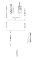
- FIG. 4 is a diagram illustrating four processes (a-1) to (a-4) included in operation (a);
- FIG. 10 is a diagram showing a specific method example for performing each of processes (a-1) to (a-4);
- FIG. 10 is a sequence diagram illustrating an operation (a) when a line is congested;
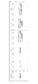
- FIG. 4 is a diagram illustrating two processes (b-1) and (b-2) included in operation (b);
- FIG. 10 is a diagram showing a specific method example for performing each of processes (b-1) and (b-2);
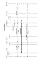
- FIG. 11 is a sequence diagram illustrating operation (b);
- FIG. 5 is a diagram illustrating five processes (c-1) to (c-5) included in operation (c);
- FIG. 10 is a diagram showing the contents of determination when performing processes (c-1) to (c-5); It is a figure which illustrates the process which a route control apparatus performs by operation
- FIG. 10 is a diagram illustrating two processes (d ⁇ 1) and (d ⁇ 2) included in operation (d); It is a sequence diagram which shows an example of operation
- FIG. 11 is a sequence diagram showing another example of operation (d);
- FIG. 10 is a diagram showing a configuration example of a communication system of a comparative example;
- FIG. 16 is a diagram showing a configuration example of a communication system 100 of a comparative example.
- the communication system 100 enables a UE (user equipment: wireless terminal) 20 to access a server 30 via a network that links 5G and wireless LAN (WiFi (registered trademark)), for example.
- 5G and wireless LAN WiFi (registered trademark)
- the UE 20 uses a predetermined reference signal and a received reference signal to calculate and transmit a CQI (Channel Quality Indicator) signal that indicates the channel quality of the communication path.
- CQI Channel Quality Indicator
- the communication system 100 includes an RU (Radio unit: radio station) 41a, a DU (Distribution unit: remote station) 42a, a CU (Central unit: aggregation base station) 43a, and a communication path through CN (Core network) 70 ( First route 110), RU 41b, DU 42b, CU 43b, and communication route (second route 120) passing through CN 70, wireless LAN access point (AP) 51, ONU (Optical Network Unit) 52, OLT ( Optical Line Terminal) 53 and a communication path (third path 130) passing through the CN 70, communication between the UE 20 and the server 30 is realized.
- RU Radio unit: radio station
- DU Distribution unit: remote station
- CU Central unit: aggregation base station
- the control device 600 determines the communication route between the UE 20 and the server 30 based on the radio environment information of the wireless LAN and the quality information of the cellular line (5G) held in the database 602 (information on the radio access section). decide.
- the CN 70 is configured such that routers 71 to 75, for example, relay data.
- the communication system 100 integrates a plurality of different wireless access systems, and enables the UE 20 and the server 30 to communicate with each other via a network including wireless access sections and wired access sections. ing.
- the control device 600 determines one of the first route 110, the second route 120, and the third route 130 as the communication route between the UE 20 and the server 30 based only on the information on the radio access section. ing. Therefore, in the communication (EtoE communication) between the UE 20 and the server 30, the communication system 100 may not necessarily have the optimal communication band and throughput, and may degrade the communication quality.
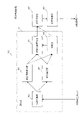
- FIG. 1 is a diagram showing a configuration example of a communication system 10 according to one embodiment.
- the communication system 10 enables the UE 20 to access the server 30 via a network that links 5G and wireless LAN (WiFi (registered trademark)), for example.
- WiFi wireless LAN
- the same reference numerals are assigned to substantially the same configurations as the communication system 100 shown in FIG.
- the communication system 10 includes a communication route (first route 210) passing through RU 41a, DU 42a, CU 43a, switching device 60, and CN 70, and a communication route (second route 210) passing through RU 41b, DU 42b, CU 43b, switching device 60, and CN 70. path 220) and a communication path (third path 230) passing through the wireless LAN access point 51, ONU 52, OLT 53, switching device 60, and CN 70.
- the switching device 60 includes, for example, an L2SW (Layer 2 switch) 61 and an L2SW (Layer 2 switch) 62, and implements communication (EtoE communication) between the UE 20 and the server 30 under the control of the routing control device 80.
- the route is switched to one of the first route 210, the second route 220, and the third route 230.
- the L2SW 61 has IF (interface) #1, IF#2, and IF#4, for example, and connects either the CU 43a or the CU 43b to the router 71 according to the control of the routing control device 80.
- the L2SW 62 has IF#3 and IF#5, for example, and connects the OLT 53 to the router 72 under the control of the routing control device 80.
- the communication system 100 integrates a plurality of different wireless access systems, and enables the UE 20 and the server 30 to communicate with each other via a network including wireless access sections and wired access sections. ing.
- FIG. 2 is a functional block diagram illustrating functions of the route control device 80 according to one embodiment.
- the route control device 80 has, for example, a measurement unit 81, a route determination unit 82, and a switching control unit 83.
- the measurement unit 81 includes, for example, an information collection unit 84, a delay time calculation unit 85, a bandwidth estimation unit 86, a route information calculation unit 87, and a storage unit 88, and acquires information in the communication system 10 via the switching device 60. , and outputs the acquired information to the route determination unit 82 .
- the measurement unit 81 collects data by continuously measuring the bandwidth and delay time of each communication path at predetermined timings.
- the information collecting unit 84 collects information such as line quality information, time stamps, retransmission request signals, etc. from each of the IFs #1 to #5 provided in the switching device 60 at a predetermined timing, and uses the collected information as a delay time calculating unit 85 and Output to band estimation section 86 .
- the information collection unit 84 collects information on other routes. In this way, the information collecting unit 84 collects, at a predetermined timing, information transmitted in each of a plurality of wireless sections and a plurality of wired sections via the switching device 60 that switches a plurality of paths.
- the delay time calculation unit 85 calculates the delay times from the end terminal device to IF#1 to IF#5 based on the information output by the information collection unit 84, and the calculated delay times are added to the route information calculation unit 87. and output to the storage unit 88 .
- the delay time calculation unit 85 calculates the delay time based on the time when the switching device 60 receives the timestamp transmitted by the server 30 .
- the delay time calculation unit 85 calculates the delay time based on the Ping transmitted to the route on which the UE 20 and the server 30 are not communicating and the throughput of the route on which the UE 20 and the server 30 are communicating. can be calculated.
- the delay time calculation unit 85 may calculate the delay time based on the time when the switching device 60 receives the timestamp transmitted by the UE 20 .
- the delay time calculation unit 85 calculates delay times for each of the plurality of wireless sections and the plurality of wired sections based on the information collected by the information collection unit 84.
- the band estimating unit 86 estimates the band (communication band or throughput) from the end terminal device to IF #1 to #5, and stores the estimated band in the route information. Output to the calculation unit 87 and the storage unit 88 .
- the band estimating unit 86 estimates the band of the wireless section and the wired section in which the downlink signal is transmitted, based on the packet interval of the downlink signal. Further, the band estimating unit 86 may estimate the band of the wireless section and the wired section based on the Ping transmitted to the route on which the UE 20 and the server 30 are not communicating. Also, the band estimation unit 86 may estimate the bands of the wireless section and the wired section based on the CQI signal transmitted by the UE 20 .
- the band estimation unit 86 estimates the band of each of the plurality of wireless sections and the plurality of wired sections based on the information collected by the information collection unit 84.
- the route information calculation unit 87 calculates the bandwidth and throughput of each EtoE route based on each delay time calculated by the delay time calculation unit 85 and each band estimated by the bandwidth estimation unit 86, and calculates the delay time, The bandwidth and throughput are output to the routing section 82 .
- the storage unit 88 stores each delay time calculated by the delay time calculation unit 85 and each band estimated by the band estimation unit 86 .
- the storage unit 88 may also store the priority of items (for example, delay time and throughput) that the communication system 10 should prioritize as communication quality.
- the route information calculation unit 87 calculates each EtoE based on the delay time and bandwidth on the CN 70 side stored in the storage unit 88. , and outputs the delay time, bandwidth, and throughput to the route determination unit 82 .
- the route determination unit 82 determines and determines the optimum route that satisfies predetermined requirements (throughput) for communication between the UE 20 and the server 30. Determined route information indicating the route is output to the switching control unit 83 .
- the route determination unit 82 determines the optimum route according to the priority. , outputs determined route information indicating the determined route to the switching control unit 83 .
- the route determination unit 82 determines a route according to a predetermined priority based on each band estimated by the band estimation unit 86 and each delay time calculated by the delay time calculation unit 85 .
- the switching control unit 83 controls switching of communication routes in the communication system 10 by controlling the switching device 60 based on the determined route information output by the route determining unit 82 .
- the switching control unit 83 controls the switching device 60 by outputting switching information for switching the IF of the switching device 60 to the switching device 60 .
- FIG. 3 is a diagram illustrating an overview of the overall operation of the communication system 10 according to one embodiment. As shown in FIG. 3, for example, when the UE 20 transmits a data transmission request to the server 30, the communication system 10 performs the following four operations (a) to (d).
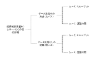
- FIG. 4 is a diagram illustrating four processes (a-1) to (a-4) included in operation (a).
- a route during data transmission is defined as a main path, and a route without data transmission is defined as a secondary path (another path).
- the operation (a) includes a process (a-1) for calculating or measuring the throughput for the route (main path) during data transmission, and a delay time for the route (main path) during data transmission.
- a process (a-2) for calculating or measuring, a process (a-3) for calculating or measuring throughput for a route without data transmission (secondary path), and a delay time for a route without data transmission (secondary path) Calculation or measurement processing (a-4) is included.
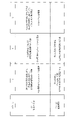
- FIG. 5 is a diagram showing a specific method example for performing each of the processes (a-1) to (a-4).
- Processing (a-1) includes, for example, the following three methods. 1. "Sneak a peek at the signal that was actually sent in the downlink” (estimate the throughput from the packet interval) 2. “Measure the transmitted data before the retransmission request and transmit the throughput value at the same time” 3. “Hold the requested throughput when executing an uplink data transmission request"
- Processing includes, for example, the following two methods. 1. "Send Ping (64 bytes, once) and set half of RTT (Round-Trip Time) as one-way delay” 2. “Send timestamp and calculate from L2SW receipt time”
- Processing includes, for example, the following two methods. 1. “Send Ping (1514 bytes, twice) and measure the throughput based on the difference in return time” 2. “Measure throughput under load with iperf"
- Processing (a-4) includes, for example, the following two methods. 1. “Send Ping (64 bytes, once) and set half of RTT as one-way delay” 2. “Send Ping (1514 bytes, twice) and calculate from RTT according to main path throughput”
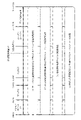
- FIG. 6 is a sequence diagram illustrating the operation (a) when the line is congested. As shown in FIG. 6, first, the UE 20 makes a data transmission request to the server 30 through the main path (S100).
- the switching device 60 transmits Ping to the server 30 via another connected path (secondary path) and measures the throughput up to the server 30 (S102). For example, if the L2SW 62 has not transmitted data from IF#5 to the server 30, the routing control device 80 transmits a packet from IF#5 of the L2SW 62 to the server 30 via the secondary path and measures the bandwidth. At the same time, the RTT is measured.
- the switching device 60 transmits the server time stamp #1 to the route control device 80 through the primary path (S106), and transmits the throughput and RTT through the secondary path (S108). Note that, when receiving a transmission request from the UE 20, the switching device 60 notifies the routing device 80 by a TCP SYN packet, an HTTP GET request, or the like.
- the information collection unit 84 collects information indicating the server time stamp #1, the RTT, and the number of transmitted packets transmitted by the switching device 60, and uses the collected information as the delay time calculation unit 85 and the bandwidth. Output to the estimation unit 86 .
- the UE 20 When the UE 20 detects an error in the data received from the server 30, it makes a retransmission request to the server 30 via the switching device 60 (S110). At this time, the switching device 60 confirms that the UE 20 has made a retransmission request, and notifies the route control device 80 that the UE 20 has made the retransmission request (that the channel quality is poor) (S112). Upon receiving the notification from the switching device 60 , the route control device 80 starts processing by the measuring section 81 , the route determining section 82 and the switching control section 83 . When the data received from the server 30 has no error (when the line is good), the UE 20 transmits a reception confirmation without making a retransmission request.
- the server 30 Upon receiving the retransmission request, the server 30 transmits the data along with the server time stamp #2 to the UE 20 via the main path (S114).
- the UE 20 transmits a reception confirmation to the server 30 via the switching device 60 (S116).
- FIG. 7 is a diagram illustrating two processes (b-1) and (b-2) included in operation (b). As shown in FIG. 7, the operation (b) includes a process (b-1) for calculating or measuring throughput and a process for calculating or measuring delay time ( b-2).
- FIG. 8 is a diagram showing a specific method example for performing each of the processes (b-1) and (b-2).
- Processing (b-1) includes, for example, the following three methods. 1.
- "DU 42 collects CQI signals as a line quality signal and transmits to routing control device 80", "Route control device 80 estimates throughput from CQI signal” 2.
- "DU 42 transmits the CQI signal as it is to the routing control device 80", "The routing control device 80 estimates the throughput from the CQI signal” 3.
- Processing (b-2) includes, for example, the following two methods. 1. "Send Ping (64 bytes, once) and set half of RTT (Round-Trip Time) as one-way delay” 2. “Send timestamp and calculate from L2SW receipt time”
- FIG. 9 is a sequence diagram illustrating operation (b).
- the UE 20 calculates channel quality based on the reference signal transmitted by the RU 41, and collectively transmits the CQI signal and the UE timestamp to the DU 42 via the main path (S200).
- DU 42 transmits channel quality signal #1 and UE time stamp to switching device 60 (S202).
- the switching device 60 then transmits the channel quality signal #1 and the UE time stamp to the route control device 80 (S204).
- the UE 20 calculates channel quality based on the reference signal transmitted by the access point 51, and transmits the CQI signal and the UE timestamp to the access point 51 via the secondary path (S206).
- the access point 51 transmits the line quality signal #2 and the time stamp to the switching device 60 (S208).
- the switching device 60 transmits the line quality signal #2 and the time stamp to the route control device 80 (S210).
- FIG. 10 is a diagram illustrating five processes (c-1) to (c-5) included in operation (c).
- the operation (c) includes a process (c-1) for calculating or measuring throughput using the optimum route determined by the route control device 80 as a single route, and a process (c-1) for calculating or measuring throughput using the optimum route as a single route. Processing to calculate or measure time (c-2), best effort processing considering both throughput and delay time (c-3), and route selection processing (c-3) according to requirements (throughput and delay time) -4).
- operation (c) includes processing (c-5) in which the optimum route determined by the route control device 80 is link aggregation (selection of multiple routes simultaneously).
- FIG. 11 is a diagram showing the contents of judgment when performing the processes (c-1) to (c-5).
- the route control device 80 determines the throughput in the process (c-1), determines the delay time in the process (c-2), and determines (c-1) and (c-2) in the process (c-3).
- the route design is determined by weighting, the optimal route design corresponding to the required throughput is determined in process (c-4), and the link aggregation is determined in process (c-5).
- the route control device 80 determines the optimum route in the communication system 10 based on, for example, the following expressions (1) to (4).
- x wifi EtoE throughput in wireless LAN (wifi)
- x du EtoE throughput in 5G (cellular)
- x demand Requested throughput in data transmission
- t wifi EtoE delay time in wireless LAN (wifi) t du : 5G (cellular ) in EtoE delay time
- the throughput and delay time in the above equation are parameters that take into consideration the loss time when the route is switched from the primary path to the secondary path, and the constant (1.2) is an arbitrary set value.
- ⁇ is a parameter (0 ⁇ 1) that weights throughput and delay time. Therefore, the closer the ⁇ is to 1, the more weight is given to the throughput, and the closer to 0 the ⁇ is, the more weight is given to the delay time.
- FIG. 12 is a diagram illustrating processing performed by the route control device 80 in operation (c).
- the route control device 80 (FIG. 1) collects the Ping information of the secondary path (1).
- the routing device 80 collects the throughput x wifi_core in the CN 70 from the router and the delay time t wifi_core in the CN 70 based on the RTT.
- the routing control device 80 collects the throughput x du_core for the server 30 based on the delay time t du_core of the main path to the server 30 via DU, the data of the main path (the number of received packets) and the time stamp. (2).
- the path control device 80 collects (3) the line quality signal and the time stamp from the DU, and collects (4) the line quality signal and the time stamp from the access point 51 as a trigger.
- the path control device 80 distributes the channel quality signal and time stamp collected by the information collection unit 84 to the delay time calculation unit 85 and the bandwidth estimation unit 86 .
- the route information calculation unit 87 calculates the network from the UE 20 to the server 30. EtoE throughput and delay time are calculated and output to the route determination unit 82 .
- the route determination unit 82 determines the optimum route based on the EtoE throughput and delay time output by the route information calculation unit, and outputs information indicating the optimum route to the switching control unit 83 . Then, the switching control unit 83 outputs to the switching device 60 a route control signal for controlling the route of the communication system 10 to be optimal. For example, the switching control unit 83 switches paths when the secondary path is optimal for maximizing throughput.
- FIG. 13 is a diagram illustrating two processes (d-1) and (d-2) included in operation (d).
- the route change method included in operation (d) includes route change by handover and route change using the ANDSF function.
- the route control device 80 uses the ANDSF function to perform control so as to transmit a route determination signal to the UE 20 as an ISRP (communication selection policy).
- FIG. 14 is a sequence diagram showing an example of operation (d). As shown in FIG. 14, when the routing control device 80 outputs a routing control signal to the switching device 60 (S300), the switching device 60 outputs a routing determination signal to the DUs (S302). The DU outputs routing signals and scheduling signals to the UE 20 (S304).
- the UE 20 transmits a data transmission request to the server 30 (S306).
- the server 30 transmits data and server time stamp #3 to the UE 20 (S308). That is, the UE 20 determines the route according to the route determination signal and establishes the communication route.
- FIG. 15 is a sequence diagram showing another example of operation (d).
- the route control device 80 outputs a route switching signal to the switching device 60 (S400).
- the switching device 60 outputs a path switching signal to the DU (S402), outputs a switching signal to the server 30 (S404), and outputs a path switching signal to the access point 51 (S406).
- the DU outputs a switching signal to the UE 20 (S408).
- the route control device 80 performs control to transmit switching signals to both the primary path and the secondary path. Then, the data and server time stamp #3 can be transmitted from the server 30 to the UE 20 (S410).
- the throughput between the UE 20 and the switching device 60 is [1] 66.4 Mbps (RU 41a), [2] 38.3 Mbps (RU 41b), and [3] 52 Mbps (access point 51). It is also assumed that the throughput between the switching device 60 and the server 30 is [4] 40 Mbps (RU41a, RU41b) and [5] 200 Mbps (path on the access point 51 side).
- the optimum communication route considering only the wireless section is the route passing through the RU 41a of [1], which has the largest throughput.
- the CN 70 side of [1] is congested, as a result, data can only be transmitted up to 40 Mbps.
- the throughput of EtoE (UE 20 to server 30) is [1] 40 Mbps (RU 41a), [2] 38.3 Mbps (RU 41b), [3] 52 Mbps (access point 51 side route).
- the optimum communication route is the access point 51 side route of [3].
- the server 30 transmits data and time stamps to the UE 20 via a specified route based on a data transmission request from the UE 20 .
- the switching device 60 transmits the time stamp to the route control device 80.
- the route control device 80 calculates the delay time (for example, 20 ms) of the route from the server 30 via the IF#4, and calculates the throughput (for example, 40 Mbps) from the received packets.
- route control device 80 when route control device 80 is notified from switching device 60 (IF#4) that there is a data transmission request, route control device 80 transmits data from switching device 60 (IF#5) to server 30 on another route. A ping is sent, and the throughput (eg, 200 Mbps) and delay time (eg, 15 ms) are measured from the response time.
- throughput eg, 200 Mbps
- delay time eg, 15 ms
- RU41a, RU41b, and access point 51 each transmit a reference signal to UE20.
- the UE 20 calculates channel quality based on the reference signals transmitted from each of the RU 41 a , RU 41 b and the access point 51 , and transmits to RU 41 a , RU 41 b and the access point 51 a connection signal including the channel quality signal and time stamp information.
- RU 41 a , RU 41 b and access point 51 each transmit line quality and time stamp to route control device 80 .
- the delay time of the route through IF#1 is 2 ms
- the delay time of the route through IF#2 is 1 ms
- the delay time of the route through IF#3 is 10 ms
- the delay time of the route through IF#4 is 1 ms.
- the delay time for the route through IF#5 is 15 ms, for example.
- the route control device 80 transmits the received line quality signal and the delay time from the UE 20 .
- the throughput and delay time of the CU 43a, CU 43b and OLT 53 are as follows.
- CU43a throughput 66.4 Mbps
- delay time 2 ms CU43b throughput 38.3 Mbps
- delay time 1 ms OLT53 throughput 129Mbps
- the EtoE throughput is the narrowest band value, so the RU41a route is 40 Mbps, the RU41b route is 38.3 Mbps, and the access point 51 route is 129 Mbps.
- the route control device 80 transmits to the UE 20 a route determination signal that determines the route via the access point 51 as the optimum route. Based on the route determination signal, the UE 20 switches the communication route to the route via the access point 51 that maximizes the throughput.
- the EtoE delay time is the sum of the delay time between the UE 20 and the switching device 60 and the delay time between the server 30 and the switching device 60. is 21 ms, and the route of the access point 51 is 25 ms.
- the route control device 80 transmits to the UE 20 a route determination signal that designates the route via the RU 41b as the communication route. Therefore, based on the route determination signal, the UE 20 switches the communication route to the route via the RU 41b with the minimum delay time.
- the throughput and delay time in EtoE are 40 Mbps and 22 ms for the route via RU 41 a, 38.3 Mbps and 21 ms for the route via RU 41 b, and 129 Mbps and 25 ms for the route via access point 51 .
- the UE 20 sets ⁇ as the line priority parameter and transmits the parameter ⁇ to the route control device 80 when transmitting the CQI.
- ⁇ is a parameter that satisfies 0 ⁇ 1.
- the route control device 80 uses ⁇ and the throughput and delay time of each route to calculate the priority P by the following formula (5), and determines the route with the maximum value of P as the optimum route.
- ⁇ 0.8 (80% priority for throughput, 20% priority for delay time).
- the route control device 80 transmits a route determination signal to the UE 20 with the route via the access point 51 as the optimum communication route.
- the UE 20 switches the communication route to the route via the access point 51 based on the route determination signal.
- the communication system 10 selects an optimal route (route settings).
- the communication system 10 can improve EtoE communication quality by consolidating a plurality of different wireless access systems such as 5G and wireless LAN.
- the communication system 10 compares each EtoE route and finds a more suitable route even when the radio environment is good but the traffic on the CN 70 side with priority is large, or when the radio environment is somewhat bad but the traffic on the CN 70 side is small. route can be selected.
- the route control device 80 collects the throughput of each route to the server 30, so that the optimum route can be quickly determined. can be done.
- each function of each of the route control device 80, UE 20, and server 30 described above may be partially or wholly configured by hardware such as PLD (Programmable Logic Device) or FPGA (Field Programmable Gate Array). Alternatively, it may be configured as a program executed by a processor such as a CPU.
- the route control device 80 can be implemented using a computer and a program, and the program can be recorded on a storage medium or provided through a network.
- 10 communication system, 20... UE, 30... server, 41a, 41b... RU, 42a, 42b... DU, 43a, 43b... CU, 51... access point, 52...ONU, 53...OLT, 60...switching device, 61...L2SW, 62...L2SW, 70...CN, 71 to 75...router, 80...route Control device, 81... Measurement unit, 82... Route determination unit, 83... Switching control unit, 84... Information collection unit, 85... Delay time calculation unit, 86... Band estimation unit , 87... Route information calculation unit, 210... First route, 220... Second route, 230... Third route
Landscapes
- Engineering & Computer Science (AREA)
- Computer Networks & Wireless Communication (AREA)
- Signal Processing (AREA)
- Health & Medical Sciences (AREA)
- Cardiology (AREA)
- General Health & Medical Sciences (AREA)
- Environmental & Geological Engineering (AREA)
- Data Exchanges In Wide-Area Networks (AREA)
- Mobile Radio Communication Systems (AREA)
Abstract
複数の経路を切替える切替装置を介して複数の無線区間及び複数の有線区間それぞれで伝送される情報を所定のタイミングで収集し、収集した情報に基づいて、複数の無線区間及び複数の有線区間それぞれの帯域を推定し、収集した情報に基づいて、複数の無線区間及び複数の有線区間それぞれの遅延時間を算出し、推定した帯域それぞれ、及び算出した遅延時間それぞれに基づいて、予め定められた優先度に応じた経路を決定し、複数の経路を切替える切替装置に対し、決定した経路に切替えるように制御する。
Description
本発明は、通信システム、経路制御装置、及び経路制御方法に関する。
通信システムにおけるトラフィックの増加に対応するために、例えば5G(第5世代移動通信システム)と、免許不要の無線周波数(アンライセンスバンド)を用いる無線LANとを連携させる技術が知られている。この場合、異なる複数の無線アクセスシステムを集約させることにより、増加したトラフィックを効率的に処理することが可能となる。
例えば、非特許文献1には、アンライセンスバンドの無線環境情報、セルラー回線の品質情報などをネットワーク上にデータベース化し、その情報に基づいて制御エンジンが独自アルゴリズムによりアクセスポイントの設定や端末の帰属先をネットワーク側から最適制御する技術が開示されている。
また、非特許文献2には、ネットワーク側からの制御により、5Gの無線セルを構成する無線アクセスの利用状況を、無線LANを含めて全体最適化し、無線通信容量を改善する技術が開示されている。
また、非特許文献3には、セルラシステムと無線LANの両方が同時に利用可能な場合に、各々のインターフェースを切替える技術と、両方のインターフェースを同時利用する技術とが開示されている。
河村憲一、外7名、「無線LANの最新動向と協調無線LAN技術」、NTT技術ジャーナル、2017年1月号、pp18-21
河村憲一、外8名、「5G時代におけるセルラー連携制御による高密度無線LANのスループット改善の検討」、信学技報、電子情報通信学会、2017年10月、vol. 117、no. 246、RCS2017-179、pp.63-68
山田曉、外1名、「セルラシステムと無線LAN間の連携技術」、電子情報通信学会、通信ソサイエティマガジン、No.43 冬号、2017年、pp.173-178
しかしながら、従来技術では、無線アクセス区間のみを考慮して最適化を行っており、例えば有線のコアネットワーク(CN)を含めたEtoE(end-to-end)での最適化を行うことはできなかった。
例えば、コアネットワーク側のトラフィックに混雑が生じた場合、無線アクセス区間の最適化を行っても、EtoEでは遅延時間が大きくなってしまったり、容量の少ない帯域に大量のトラフィックが流れてしまうことがあった。
また、従来技術では、回線情報をデータベース化した後に最適化を行う場合、通信経路が(パス)が切り替わるまでに時間がかかり、遅延が大きい状態が続いてしまうことがあった。
本発明は、上述した課題を鑑みてなされたものであり、異なる複数の無線アクセスシステムを集約させて、EtoEでの通信品質を向上させることができる通信システム、経路制御装置、及び経路制御方法を提供することを目的とする。
本発明の一実施形態にかかる経路制御装置は、無線端末がサーバと通信を行う経路を、異なる複数の無線区間の少なくともいずれかと複数の有線区間のいずれかとを含む複数の経路のいずれかに切替える制御を行う経路制御装置において、複数の前記経路を切替える切替装置を介して複数の無線区間及び複数の有線区間それぞれで伝送される情報を所定のタイミングで収集する情報収集部と、前記情報収集部が収集した情報に基づいて、複数の無線区間及び複数の有線区間それぞれの帯域を推定する帯域推定部と、前記情報収集部が収集した情報に基づいて、複数の無線区間及び複数の有線区間それぞれの遅延時間を算出する遅延時間算出部と、前記帯域推定部が推定した帯域それぞれ、及び前記遅延時間算出部が算出した遅延時間それぞれに基づいて、予め定められた優先度に応じた経路を決定する経路決定部と、複数の前記経路を切替える切替装置に対し、前記経路決定部が決定した経路に切替えるように制御する切替制御部とを有することを特徴とする。
また、本発明の一実施形態にかかる通信システムは、無線端末が異なる複数の無線区間の少なくともいずれかと複数の有線区間のいずれかとを含む複数の経路のいずれかを介してサーバと通信を行う通信システムにおいて、複数の前記経路を切替える切替装置と、前記切替装置を介して複数の無線区間及び複数の有線区間それぞれにおけるスループット及び遅延時間を所定のタイミングで取得し、取得したスループット及び遅延時間に基づいて、予め定められた優先度に応じて前記切替装置が切替える経路を制御する経路制御装置とを有することを特徴とする。
また、本発明の一実施形態にかかる経路制御方法は、無線端末がサーバと通信を行う経路を、異なる複数の無線区間の少なくともいずれかと複数の有線区間のいずれかとを含む複数の経路のいずれかに切替える制御を行う経路制御方法において、複数の前記経路を切替える切替装置を介して複数の無線区間及び複数の有線区間それぞれで伝送される情報を所定のタイミングで収集する情報収集工程と、収集した情報に基づいて、複数の無線区間及び複数の有線区間それぞれの帯域を推定する帯域推定工程と、収集した情報に基づいて、複数の無線区間及び複数の有線区間それぞれの遅延時間を算出する遅延時間算出工程と、推定した帯域それぞれ、及び算出した遅延時間それぞれに基づいて、予め定められた優先度に応じた経路を決定する経路決定工程と、複数の前記経路を切替える切替装置に対し、決定した経路に切替えるように制御する切替制御工程とを含むことを特徴とする。
本発明によれば、異なる複数の無線アクセスシステムを集約させて、EtoEでの通信品質を向上させることができる。
まず、本発明がなされるに至った背景について説明する。図16は、比較例の通信システム100の構成例を示す図である。通信システム100は、例えば5Gと無線LAN(WiFi(登録商標))を連携させたネットワークを介して、UE(User equipment:無線端末)20がサーバ30に対してアクセスすることを可能にしている。
なお、UE20は、予め定められた参照信号と、受信した参照信号とを用いて、通信経路の回線品質を示すCQI(Channel Quality Indicator:チャネル品質指標)信号を算出して送信する機能を備えている。
例えば、通信システム100は、RU(Radio unit:無線局)41a、DU(Distribution unit:リモート局)42a、CU(Central unit:集約基地局)43a、及びCN(Core network)70を通る通信経路(第1経路110)と、RU41b、DU42b、CU43b、及びCN70を通る通信経路(第2経路120)と、無線LANのアクセスポイント(Access point:AP)51、ONU(Optical Network Unit)52、OLT(Optical Line Terminal)53、及びCN70を通る通信経路(第3経路130)のいずれかの通信経路を介して、UE20とサーバ30との通信を実現している。
制御装置600は、データベース602が保持している無線LANの無線環境情報及びセルラー回線(5G)の品質情報など(無線アクセス区間の情報)に基づいて、UE20とサーバ30とが行う通信の経路を決定する。なお、CN70は、例えばルータ71~75などがデータを中継するように構成されている。
このように、通信システム100は、異なる複数の無線アクセスシステムを集約させており、無線アクセス区間及び有線アクセス区間を含むネットワークを介して、UE20とサーバ30とが相互に通信を行うことを可能にしている。
通信システム100は、制御装置600が無線アクセス区間の情報のみに基づいて、UE20とサーバ30とが行う通信の経路を第1経路110、第2経路120及び第3経路130のいずれかに決定している。このため、通信システム100は、UE20とサーバ30との通信(EtoEの通信)においては、通信帯域やスループットが必ずしも最適であるとはいえず、通信品質を低下させる場合がある。
次に、一実施形態にかかる通信システムについて、以下のように図面を用いて説明する。図1は、一実施形態にかかる通信システム10の構成例を示す図である。通信システム10は、例えば5Gと無線LAN(WiFi(登録商標))を連携させたネットワークを介して、UE20がサーバ30に対してアクセスすることを可能にしている。なお、図1に示した通信システム10において、図16に示した通信システム100の構成と実質的に同一の構成には同一の符号が付してある。
例えば、通信システム10は、RU41a、DU42a、CU43a、切替装置60、及びCN70を通る通信経路(第1経路210)と、RU41b、DU42b、CU43b、切替装置60、及びCN70を通る通信経路(第2経路220)と、無線LANのアクセスポイント51、ONU52、OLT53、切替装置60、及びCN70を通る通信経路(第3経路230)のいずれかの通信経路を介して、UE20とサーバ30との通信を実現している。
切替装置60は、例えばL2SW(レイヤ2スイッチ)61及びL2SW(レイヤ2スイッチ)62を備え、経路制御装置80の制御に応じて、UE20とサーバ30との通信(EtoEの通信)を実現する通信経路を第1経路210、第2経路220、及び第3経路230のいずれかに切替える。
L2SW61は、例えばIF(インターフェース)#1、IF#2、及びIF#4を備え、経路制御装置80の制御に応じて、CU43a又はCU43bのいずれかをルータ71に接続する。L2SW62は、例えばIF#3及びIF#5を備え、経路制御装置80の制御に応じて、OLT53をルータ72に接続する。
このように、通信システム100は、異なる複数の無線アクセスシステムを集約させており、無線アクセス区間及び有線アクセス区間を含むネットワークを介して、UE20とサーバ30とが相互に通信を行うことを可能にしている。
次に、一実施形態にかかる経路制御装置80が有する機能について詳述する。図2は、一実施形態にかかる経路制御装置80が有する機能を例示する機能ブロック図である。図2に示すように、経路制御装置80は、例えば測定部81、経路決定部82、及び切替制御部83を有する。
測定部81は、例えば情報収集部84、遅延時間算出部85、帯域推定部86、経路情報算出部87、及び記憶部88を有し、切替装置60を介して通信システム10における情報を取得し、取得した情報を経路決定部82に対して出力する。例えば、測定部81は、所定のタイミングで継続的に各通信経路の帯域と遅延時間をそれぞれ測定することによって収集する。
情報収集部84は、切替装置60が備えるIF#1~#5それぞれから回線品質情報、タイムスタンプ、再送要求信号などの情報を所定のタイミングで収集し、収集した情報を遅延時間算出部85及び帯域推定部86に対して出力する。
例えば、情報収集部84は、UE20が複数の経路のいずれかを介してサーバ30に接続要求をしたときに、他の経路の情報を収集する。このように、情報収集部84は、複数の経路を切替える切替装置60を介して複数の無線区間及び複数の有線区間それぞれで伝送される情報を所定のタイミングで収集する。
遅延時間算出部85は、情報収集部84が出力した情報に基づいて、end端末となる装置からIF#1~#5までの遅延時間をそれぞれ算出し、算出した遅延時間を経路情報算出部87及び記憶部88に対して出力する。
例えば、遅延時間算出部85は、サーバ30が送信したタイムスタンプを切替装置60が受信した時間に基づいて遅延時間を算出する。また、遅延時間算出部85は、UE20とサーバ30とが通信を行っていない経路に対して送信されたPing、及びUE20とサーバ30とが通信を行っている経路のスループットに基づいて遅延時間を算出してもよい。また、遅延時間算出部85は、UE20が送信したタイムスタンプを切替装置60が受信した時間に基づいて遅延時間を算出してもよい。
このように、遅延時間算出部85は、情報収集部84が収集した情報に基づいて、複数の無線区間及び複数の有線区間それぞれの遅延時間を算出する。
帯域推定部86は、情報収集部84が出力した情報に基づいて、end端末となる装置からIF#1~#5までの帯域(通信帯域又はスループット)をそれぞれ推定し、推定した帯域を経路情報算出部87及び記憶部88に対して出力する。
例えば、帯域推定部86は、下り信号のパケット間隔に基づいて、下り信号を伝送している無線区間及び有線区間の帯域を推定する。また、帯域推定部86は、UE20とサーバ30とが通信を行っていない経路に対して送信されたPingに基づいて無線区間及び有線区間の帯域を推定してもよい。また、帯域推定部86は、UE20が送信するCQI信号に基づいて、無線区間及び有線区間の帯域を推定してもよい。
このように、帯域推定部86は、情報収集部84が収集した情報に基づいて、複数の無線区間及び複数の有線区間それぞれの帯域を推定する。
経路情報算出部87は、遅延時間算出部85が算出した遅延時間それぞれと、帯域推定部86が推定した帯域それぞれとに基づいて、各EtoEの経路の帯域とスループットをそれぞれ算出し、遅延時間、帯域及びスループットを経路決定部82に対して出力する。
記憶部88は、遅延時間算出部85が算出した遅延時間それぞれ、及び帯域推定部86が推定した帯域それぞれを記憶する。また、記憶部88は、通信システム10が通信品質として優先すべき項目(例えば遅延時間及びスループット)の優先度を記憶していてもよい。
なお、経路情報算出部87は、記憶部88がCN70側の遅延時間及び帯域を記憶している場合には、記憶部88が記憶しているCN70側の遅延時間及び帯域に基づいて、各EtoEの経路の帯域とスループットをそれぞれ算出し、遅延時間、帯域及びスループットを経路決定部82に対して出力する。
経路決定部82は、経路情報算出部87の算出結果に基づいて、UE20とサーバ30との間の通信に対して予め定められた要求条件(スループット)を満たす最適な経路を決定し、決定した経路を示す決定経路情報を切替制御部83に対して出力する。
なお、経路決定部82は、記憶部88が通信品質として優先すべき項目(例えば遅延時間及び帯域)の優先度を記憶している場合には、当該優先度に応じて最適な経路を決定し、決定した経路を示す決定経路情報を切替制御部83に対して出力する。このように、経路決定部82は、帯域推定部86が推定した帯域それぞれ、及び遅延時間算出部85が算出した遅延時間それぞれに基づいて、予め定められた優先度に応じた経路を決定する。
切替制御部83は、経路決定部82が出力した決定経路情報に基づいて切替装置60を制御することにより、通信システム10における通信経路を切替える制御を行う。例えば、切替制御部83は、切替装置60のIFを切替える切替情報を切替装置60に対して出力することによって切替装置60を制御する。
次に、通信システム10の動作例についてさらに説明する。図3は、一実施形態にかかる通信システム10の全体動作の概要を例示する図である。図3に示すように、通信システム10は、例えばUE20がサーバ30に対してデータ送信要求を送信すると、以下に示す4つの動作(a)~(d)を行う。
(a):サーバ30と経路制御装置80との間のスループット・遅延時間測定
(b):UE20と経路制御装置80との間のスループット・遅延時間測定
(c):経路制御装置80による経路決定
(d):決定した通信経路によりUE20からサーバ30へデータ送信
(b):UE20と経路制御装置80との間のスループット・遅延時間測定
(c):経路制御装置80による経路決定
(d):決定した通信経路によりUE20からサーバ30へデータ送信
まず、動作(a)について説明する。図4は、動作(a)に含まれる4つの処理(a-1)~(a-4)を例示する図である。経路制御装置80とサーバ30の間には、複数の経路があり(図1参照)、データ送信中の経路を主パスとし、データ送信なしの経路を副パス(別パス)とする。
図4に示すように、動作(a)には、データ送信中の経路(主パス)に対するスループットを算出又は測定する処理(a-1)と、データ送信中の経路(主パス)に対する遅延時間を算出又は測定する処理(a-2)と、データ送信なしの経路(副パス)に対するスループットを算出又は測定する処理(a-3)と、データ送信なしの経路(副パス)に対する遅延時間を算出又は測定する処理(a-4)とが含まれる。
図5は、処理(a-1)~(a-4)それぞれを行う具体的な方法例を示す図である。処理(a-1)には、例えば次の3つの方法などがある。
1.「下りで実際に送られてきた信号を盗み見る」(パケット間隔からスループットを推定)
2.「再送要求前の送信データを測定し、スループットの値を同時に送信する」
3.「上りデータ送信要求を実施時に、要求スループットを保持する」
1.「下りで実際に送られてきた信号を盗み見る」(パケット間隔からスループットを推定)
2.「再送要求前の送信データを測定し、スループットの値を同時に送信する」
3.「上りデータ送信要求を実施時に、要求スループットを保持する」
処理(a-2)には、例えば次の2つの方法などがある。
1.「Pingを送信(64byte、1回)し、RTT(Round-Trip Time)の半分を片道遅延とする」
2.「タイムスタンプを送信し、L2SWの受取時間から算出する」
1.「Pingを送信(64byte、1回)し、RTT(Round-Trip Time)の半分を片道遅延とする」
2.「タイムスタンプを送信し、L2SWの受取時間から算出する」
処理(a-3)には、例えば次の2つの方法などがある。
1.「Pingを送信(1514byte、2回)し、戻る時間差によりスループットを測定する」
2.「iperfにより負荷をかけてスループットを測定する」
1.「Pingを送信(1514byte、2回)し、戻る時間差によりスループットを測定する」
2.「iperfにより負荷をかけてスループットを測定する」
処理(a-4)には、例えば次の2つの方法などがある。
1.「Pingを送信(64byte、1回)し、RTTの半分を片道遅延とする」
2.「Pingを送信(1514byte、2回)し、主パスのスループットに応じてRTTから算出する」
1.「Pingを送信(64byte、1回)し、RTTの半分を片道遅延とする」
2.「Pingを送信(1514byte、2回)し、主パスのスループットに応じてRTTから算出する」
図6は、回線が混雑していた場合の動作(a)を例示するシーケンス図である。図6に示したように、まず、UE20は、サーバ30に対して主パスによりデータ送信要求を行う(S100)。
主パスにおいてデータ送信要求があった場合、切替装置60は、他の接続されているパス(副パス)によりPingをサーバ30へ送信し、サーバ30までのスループットを測定する(S102)。例えば、L2SW62がIF#5からデータをサーバ30に向けて送信していない場合、経路制御装置80は、L2SW62のIF#5から副パスによりサーバ30に対してパケットを送信し、帯域を測定するとともに、RTTの測定を行う。
主パスによりデータ送信要求をされたサーバ30は、主パスによりUE20に対してサーバタイムスタンプ#1とともにデータを送信する(S104)。
切替装置60は、経路制御装置80に対して主パスによりサーバタイムスタンプ#1を送信し(S106)、副パスによりスループットとRTTを送信する(S108)。なお、切替装置60は、UE20から送信要求があった場合に、TCPのSYNパケット又はHTTPのGETリクエストなどにより、経路制御装置80に対する通知を行う。
経路制御装置80において、情報収集部84は、切替装置60が送信したサーバタイムスタンプ#1、RTT、及び送信されたパケット数を示す情報を収集し、収集した情報を遅延時間算出部85及び帯域推定部86に対して出力する。
UE20は、サーバ30から受信したデータに誤りを検出した場合、切替装置60を介してサーバ30に再送要求を行う(S110)。このとき、切替装置60は、UE20が再送要求したことを確認し、UE20が再送要求を行ったこと(回線品質がよくないこと)を経路制御装置80に対して通知する(S112)。経路制御装置80は、切替装置60から通知を受け取ると、測定部81、経路決定部82、及び切替制御部83による処理を開始する。なお、UE20は、サーバ30から受信したデータに誤りがない場合(回線が良好な場合)には、再送要求をすることなく、受信確認を送信する。
再送要求を受信したサーバ30は、主パスによりUE20に対してサーバタイムスタンプ#2とともにデータを送信する(S114)。
UE20は、サーバ30から受信したデータに誤りがない場合には、切替装置60を介して受信確認をサーバ30へ送信する(S116)。
次に、動作(b)について説明する。図7は、動作(b)に含まれる2つの処理(b-1)、(b-2)を例示する図である。図7に示すように、動作(b)には、UE20と経路制御装置80との間の経路において、スループットを算出又は測定する処理(b-1)と、遅延時間を算出又は測定する処理(b-2)とが含まれる。
図8は、処理(b-1)、(b-2)それぞれを行う具体的な方法例を示す図である。処理(b-1)には、例えば次の3つの方法などがある。
1.「DU42がCQI信号をまとめて回線品質信号とし、経路制御装置80へ送信する」、「経路制御装置80がCQI信号からスループットを推定する」
2.「DU42がCQI信号をそのまま経路制御装置80へ送信する」、「経路制御装置80がCQI信号からスループットを推定する」
3.「Hybrid ARQ(Automatic Repeat reQuest))又はRLC(Radio Link Control)での再送要求情報に基づいて、経路制御装置80がパケットロスを算出する」、「経路制御装置80がスループットを推定する」
1.「DU42がCQI信号をまとめて回線品質信号とし、経路制御装置80へ送信する」、「経路制御装置80がCQI信号からスループットを推定する」
2.「DU42がCQI信号をそのまま経路制御装置80へ送信する」、「経路制御装置80がCQI信号からスループットを推定する」
3.「Hybrid ARQ(Automatic Repeat reQuest))又はRLC(Radio Link Control)での再送要求情報に基づいて、経路制御装置80がパケットロスを算出する」、「経路制御装置80がスループットを推定する」
処理(b-2)には、例えば次の2つの方法などがある。
1.「Pingを送信(64byte、1回)し、RTT(Round-Trip Time)の半分を片道遅延とする」
2.「タイムスタンプを送信し、L2SWの受取時間から算出する」
1.「Pingを送信(64byte、1回)し、RTT(Round-Trip Time)の半分を片道遅延とする」
2.「タイムスタンプを送信し、L2SWの受取時間から算出する」
図9は、動作(b)を例示するシーケンス図である。図9に示したように、まず、UE20は、RU41が送信した参照信号に基づいて回線品質を算出し、主パスによりDU42に対してCQI信号及びUEタイムスタンプをまとめて送信する(S200)。DU42は、切替装置60に対して回線品質信号#1、UEタイムスタンプを送信する(S202)。そして、切替装置60は、経路制御装置80に対して回線品質信号#1、UEタイムスタンプを送信する(S204)。
また、UE20は、アクセスポイント51が送信した参照信号に基づいて回線品質を算出し、副パスによりアクセスポイント51に対してCQI信号及びUEタイムスタンプを送信する(S206)。アクセスポイント51は、切替装置60に対して回線品質信号#2、タイムスタンプを送信する(S208)。切替装置60は、経路制御装置80に対して回線品質信号#2、タイムスタンプを送信する(S210)。
次に、動作(c)について説明する。図10は、動作(c)に含まれる5つの処理(c-1)~(c-5)を例示する図である。図10に示すように、動作(c)には、経路制御装置80が決定した最適経路を単一経路としてスループットを算出又は測定する処理(c-1)と、最適経路を単一経路として遅延時間を算出又は測定する処理(c-2)と、スループットと遅延時間を共に考慮したベストエフォートの処理(c-3)と、要求条件(スループットと遅延時間)に応じて経路選択する処理(c-4)とが含まれる。
さらに、動作(c)には、経路制御装置80が決定した最適経路がリンクアグリゲーション(複数経路同時選択)となる処理(c-5)が含まれる。
図11は、処理(c-1)~(c-5)を行う場合に判断する内容をそれぞれ示す図である。経路制御装置80は、処理(c-1)ではスループットを判断し、処理(c-2)では遅延時間を判断し、処理(c-3)では(c-1)・(c-2)の重みづけを行って経路設計を判断し、処理(c-4)では必要スループットに応じた最適な経路設計を判断し、処理(c-5)ではリンクアグリゲーションを判断する。
より具体的には、経路制御装置80は、例えば下式(1)~(4)に基づいて、通信システム10における最適な経路を決定する。




xwifi :無線LAN(wifi)におけるEtoEのスループット
xdu :5G(セルラー)におけるEtoEのスループット
xdemand:データ送信における要求スループット
twifi :無線LAN(wifi)におけるEtoEの遅延時間
tdu :5G(セルラー)におけるEtoEの遅延時間
なお、上式におけるスループットと遅延時間は、主パスから副パスへ経路を切替える場合のロス時間を顧慮したパラメータであり、定数(1.2)は、任意の設定値である。
αは、スループットと遅延時間の重みづけを行うパラメータ(0<α<1)である。したがって、αが1に近いほどスループットに重みをおき、αが0に近いほど遅延時間に重みをおくこととなる。
図12は、動作(c)により経路制御装置80が行う処理を例示する図である。経路制御装置80(図1)は、副パスのPing情報を収集する(1)。例えば、経路制御装置80は、CN70におけるスループットxwifi_coreをルータから収集し、CN70における遅延時間twifi_coreをRTTに基づいて収集する。
また、経路制御装置80は、DUを介した主パスのサーバ30までの遅延時間tdu_coreと、主パスのデータ(パケットの受信数)とタイムスタンプに基づいて、サーバ30に対するスループットxdu_coreを収集する(2)。
次に、経路制御装置80は、DUから回線品質信号及びタイムスタンプを収集(3)し、アクセスポイント51から回線品質信号及びタイムスタンプを収集(4)したことを契機として、主パスのスループットxdu_access及び遅延時間tdu_accessと、副パスのスループットxwifi_access及び遅延時間twifi_accessを推定する。
このとき、経路制御装置80は、情報収集部84が収集した回線品質信号及びタイムスタンプを遅延時間算出部85及び帯域推定部86に振り分ける。
そして、経路情報算出部87は、遅延時間算出部85及び帯域推定部86から入力されたUE20から経路制御装置80までの遅延時間と帯域(スループット)に基づいて、UE20からサーバ30までのネットワークのEtoEのスループット及び遅延時間を算出し、経路決定部82に対して出力する。
経路決定部82は、経路情報算出部が出力したEtoEのスループット及び遅延時間に基づいて最適経路を決定し、切替制御部83に対して最適経路を示す情報を出力する。そして、切替制御部83は、通信システム10の経路が最適となるように制御する経路制御信号を切替装置60に対して出力する。例えば、切替制御部83は、副パスがスループットの最大化に最適である場合には、経路の切替を行う。
次に、動作(d)について説明する。図13は、動作(d)に含まれる2つの処理(d-1)、(d-2)を例示する図である。図13に示すように、動作(d)に含まれる経路変更の方法として、ハンドオーバーによる経路変更と、ANDSF機能を用いた経路変更とがある。なお、経路制御装置80は、ANDSF機能を用いて、ISRP(通信選択ポリシー)として経路決定信号をUE20へ送信するように制御を行う。
図14は、動作(d)の一例を示すシーケンス図である。図14に示したように、経路制御装置80が切替装置60に対して経路制御信号を出力すると(S300)、切替装置60はDUに対して経路決定信号を出力する(S302)。DUは、UE20に対して経路決定信号及びスケジューリング信号を出力する(S304)。
UE20は、サーバ30に対してデータ送信要求を送信する(S306)。サーバ30は、UE20に対してデータ送信、及びサーバタイムスタンプ#3を送信する(S308)。つまり、UE20は、経路決定信号に従って経路を確定し、通信経路を確立する。
図15は、動作(d)の他の例を示すシーケンス図である。図15に示したように、経路制御装置80は、切替装置60に対して経路切替信号を出力する(S400)。切替装置60は、DUに対して経路切替信号を出力し(S402)、サーバ30に対して切替信号を出力し(S404)、アクセスポイント51に対して経路切替信号を出力する(S406)。また、DUは、UE20に対して切替信号を出力する(S408)。
つまり、経路制御装置80は、主パスと副パスの両方に切替信号を送信する制御を行う。そして、サーバ30からUE20に対するデータ及びサーバタイムスタンプ#3の送信が可能になる(S410)。
次に、通信システム10(図1)の具体的な実施例について説明する。例えば、UE20と切替装置60との間のスループットが[1]66.4Mbps(RU41a)、[2]38.3Mbps(RU41b)、[3]52Mbps(アクセスポイント51)であるとする。また、切替装置60とサーバ30との間のスループットが[4]40Mbps(RU41a、RU41b)、[5]200Mbps(アクセスポイント51側経路)であるとする。
このとき、無線区間のみを考慮した最適な通信経路は、最もスループットが大きくなる[1]のRU41aを通る経路となる。しかし、[1]のCN70側が混雑していると、結果として40Mbpsまでしかデータを伝送できないこととなる。
一方、EtoE(UE20~サーバ30)のスループットは、[1]40Mbps(RU41a)、[2]38.3Mbps(RU41b)、[3]52Mbps(アクセスポイント51側経路)となる。つまり、最適な通信経路は、[3]のアクセスポイント51側経路となる。
以下、通信システム10の上述した動作について、より具体的な例を用いて説明する。例えば、サーバ30は、UE20からのデータ送信要求に基づいて、指定された経路を介してUE20にデータとタイムスタンプを送信する。
切替装置60は、タイムスタンプを経路制御装置80に送信する。経路制御装置80は、サーバ30からIF#4を介した経路の遅延時間(例えば20ms)を算出し、受信したパケットからスループット(例えば40Mbps)を算出する。
また、経路制御装置80は、データ送信要求があったことを切替装置60(IF#4)から通知されると、別の経路に対して切替装置60(IF#5)からサーバ30に向けてPingを送信し、応答時間からスループット(例えば200Mbps)と遅延時間(例えば15ms)を測定する。
RU41a、RU41b及びアクセスポイント51は、それぞれUE20に対して参照信号を送信する。UE20は、RU41a、RU41b及びアクセスポイント51それぞれから送信された参照信号に基づいて回線品質を算出し、回線品質信号とタイムスタンプ情報をまとめた接続信号をRU41a、RU41b及びアクセスポイント51に送信する。
この時、RU41aの回線品質はCQI=8、RU41bの回線品質はCQI=5、アクセスポイント51の回線品質はMCS=10とする。RU41a、RU41b及びアクセスポイント51は、それぞれ回線品質とタイムスタンプを経路制御装置80に送信する。
なお、IF#1を介した経路の遅延時間を例えば2msとし、IF#2を介した経路の遅延時間を例えば1msとし、IF#3を介した経路の遅延時間を例えば10msとし、IF#4を介した経路の遅延時間を例えば20msとし、IF#5を介した経路の遅延時間を例えば15msとする。経路制御装置80は、受信した回線品質信号とUE20からの遅延時間を送信する。
この時、5Gの無線区間も無線LANの区間も帯域幅を20MHzとすると、CU43a、CU43b及びOLT53のスループットと遅延時間は以下のようになる。
CU43a:スループット66.4Mbps、遅延時間2ms
CU43b:スループット38.3Mbps、遅延時間1ms
OLT53:スループット129Mbps、遅延時間20ms
CU43a:スループット66.4Mbps、遅延時間2ms
CU43b:スループット38.3Mbps、遅延時間1ms
OLT53:スループット129Mbps、遅延時間20ms
EtoEのスループットは、最も狭い帯域の値となるため、RU41aの経路は40Mbps、RU41bの経路は38.3Mbps、アクセスポイント51の経路は129Mbpsとなる。
そして、経路制御装置80は、スループットを優先させる場合、アクセスポイント51を介する経路を最適な経路と決定する経路決定信号をUE20に送信する。UE20は、経路決定信号に基づいて、スループットが最大となるアクセスポイント51を介する経路に通信経路を切り替える。
なお、EtoEの遅延時間は、UE20と切替装置60との間の遅延時間と、サーバ30と切替装置60との間の遅延時間を加算したものとなるため、RU41aの経路は22ms、RU41bの経路は21ms、アクセスポイント51の経路は25msとなる。
そのため、経路制御装置80は、遅延時間を優先させる場合、RU41bを介する経路を通信経路とする経路決定信号をUE20に送信する。従って、UE20は、経路決定信号に基づいて、最小の遅延時間となるRU41bを介する経路に通信経路を切替える。
次に、EtoEにおけるスループットと遅延時間を共に考慮した通信システム10の動作例について説明する。EtoEでのスループットと遅延時間は、RU41aを介する経路で40Mbpsと22ms、RU41bを介する経路で38.3Mbpsと21ms、アクセスポイント51を介する経路で129Mbpsと25msとなる。
例えば、UE20は、回線優先パラメータをαとして、CQIを送信する時にパラメータαを経路制御装置80に送信する。αは、0<α<1となる値であり、1に近いほどスループットを考慮した経路選択となり、0に近いほど遅延時間を考慮した経路選択となるパラメータである。
経路制御装置80は、αと各経路のループット及び遅延時間を用いて下式(5)により優先度Pを算出し、Pの値が最大となる経路を最適な経路として決定する。ここでは、α=0.8(スループットの優先度80%、遅延時間の優先度20%)とする。

つまり、EtoEでの優先度Pは、RU41aを介する経路で10.3、RU41bを介する経路で10.0、アクセスポイント51を介する経路で25.6となる。よって、経路制御装置80は、アクセスポイント51を介する経路を最適な通信経路として、経路決定信号をUE20に送信する。UE20は、経路決定信号に基づいて、アクセスポイント51を介する経路に通信経路を切替える。
このように、実施形態にかかる通信システム10は、無線区間だけではなく、無線以外の区間の通信品質にも基づいて、EtoE(UE20とサーバ30との間)の経路について最適な経路選択(経路設定)を行うことができる。
また、実施形態にかかる通信システム10は、例えば5Gや無線LANなどの異なる複数の無線アクセスシステムを集約させて、EtoEでの通信品質を向上させることができる。
つまり、通信システム10は、無線環境はよいが優先のCN70側でトラフィックが多い場合や、無線環境はやや悪いがCN70側のトラフィックが少ない場合などでも、EtoEの各経路を比較して、より適した経路を選択することができる。
また、通信システム10は、UE20からサーバ30に対してデータ送信要求を行ったときに、経路制御装置80がサーバ30までの各経路のスループットを収集するので、迅速に最適な経路を決定することができる。
なお、上述した経路制御装置80、UE20、及びサーバ30それぞれが有する各機能は、それぞれ一部又は全部がPLD(Programmable Logic Device)やFPGA(Field Programmable Gate Array)等のハードウェアによって構成されてもよいし、CPU等のプロセッサが実行するプログラムとして構成されてもよい。
例えば、一実施形態にかかる経路制御装置80は、コンピュータとプログラムを用いて実現することができ、プログラムを記憶媒体に記録することも、ネットワークを通して提供することも可能である。
10・・・通信システム、20・・・UE、30・・・サーバ、41a,41b・・・RU、42a,42b・・・DU、43a,43b・・・CU、51・・・アクセスポイント、52・・・ONU、53・・・OLT、60・・・切替装置、61・・・L2SW、62・・・L2SW、70・・・CN、71~75・・・ルータ、80・・・経路制御装置、81・・・測定部、82・・・経路決定部、83・・・切替制御部、84・・・情報収集部、85・・・遅延時間算出部、86・・・帯域推定部、87・・・経路情報算出部、210・・・第1経路、220・・・第2経路、230・・・第3経路
Claims (8)
- 無線端末がサーバと通信を行う経路を、異なる複数の無線区間の少なくともいずれかと複数の有線区間のいずれかとを含む複数の経路のいずれかに切替える制御を行う経路制御装置において、
複数の前記経路を切替える切替装置を介して複数の無線区間及び複数の有線区間それぞれで伝送される情報を所定のタイミングで収集する情報収集部と、
前記情報収集部が収集した情報に基づいて、複数の無線区間及び複数の有線区間それぞれの帯域を推定する帯域推定部と、
前記情報収集部が収集した情報に基づいて、複数の無線区間及び複数の有線区間それぞれの遅延時間を算出する遅延時間算出部と、
前記帯域推定部が推定した帯域それぞれ、及び前記遅延時間算出部が算出した遅延時間それぞれに基づいて、予め定められた優先度に応じた経路を決定する経路決定部と、
複数の前記経路を切替える切替装置に対し、前記経路決定部が決定した経路に切替えるように制御する切替制御部と
を有することを特徴とする経路制御装置。 - 前記情報収集部は、
前記無線端末が前記経路のいずれかを介して前記サーバに接続要求をしたときに、他の前記経路の情報を収集すること
を特徴とする請求項1に記載の経路制御装置。 - 前記帯域推定部が推定した帯域それぞれ、及び前記遅延時間算出部が算出した遅延時間それぞれを記憶する記憶部をさらに有し、
前記経路決定部は、
前記記憶部が複数の有線区間それぞれの帯域及び遅延時間を記憶している場合には、前記記憶部が記憶している帯域及び遅延時間に基づいて経路を決定すること
を特徴とする請求項1又は2に記載の経路制御装置。 - 前記経路決定部は、
前記無線端末と前記サーバとの間の通信に対して予め定められた条件を満たすように経路を決定すること
を特徴とする請求項1~3のいずれか1項に記載の経路制御装置。 - 前記帯域推定部は、
下り信号のパケット間隔に基づいて、下り信号を伝送している無線区間及び有線区間の帯域を推定、前記無線端末と前記サーバとが通信を行っていない経路に対して送信されたPingに基づいて無線区間及び有線区間の帯域を推定、又は、前記無線端末が送信するCQI信号に基づいて、無線区間及び有線区間の帯域を推定すること
を特徴とする請求項1~4のいずれか1項に記載の経路制御装置。 - 前記遅延時間算出部は、
前記サーバが送信したタイムスタンプを前記切替装置が受信した時間に基づいて遅延時間を算出、前記無線端末と前記サーバとが通信を行っていない経路に対して送信されたPing、及び前記無線端末と前記サーバとが通信を行っている経路のスループットに基づいて遅延時間を算出、又は、前記無線端末が送信したタイムスタンプを前記切替装置が受信した時間に基づいて遅延時間を算出すること
を特徴とする請求項1~5のいずれか1項に記載の経路制御装置。 - 無線端末が異なる複数の無線区間の少なくともいずれかと複数の有線区間のいずれかとを含む複数の経路のいずれかを介してサーバと通信を行う通信システムにおいて、
複数の前記経路を切替える切替装置と、
前記切替装置を介して複数の無線区間及び複数の有線区間それぞれにおけるスループット及び遅延時間を所定のタイミングで取得し、取得したスループット及び遅延時間に基づいて、予め定められた優先度に応じて前記切替装置が切替える経路を制御する経路制御装置と
を有することを特徴とする通信システム。 - 無線端末がサーバと通信を行う経路を、異なる複数の無線区間の少なくともいずれかと複数の有線区間のいずれかとを含む複数の経路のいずれかに切替える制御を行う経路制御方法において、
複数の前記経路を切替える切替装置を介して複数の無線区間及び複数の有線区間それぞれで伝送される情報を所定のタイミングで収集する情報収集工程と、
収集した情報に基づいて、複数の無線区間及び複数の有線区間それぞれの帯域を推定する帯域推定工程と、
収集した情報に基づいて、複数の無線区間及び複数の有線区間それぞれの遅延時間を算出する遅延時間算出工程と、
推定した帯域それぞれ、及び算出した遅延時間それぞれに基づいて、予め定められた優先度に応じた経路を決定する経路決定工程と、
複数の前記経路を切替える切替装置に対し、決定した経路に切替えるように制御する切替制御工程と
を含むことを特徴とする経路制御方法。
Priority Applications (2)
| Application Number | Priority Date | Filing Date | Title |
|---|---|---|---|
| PCT/JP2021/007210 WO2022180751A1 (ja) | 2021-02-25 | 2021-02-25 | 通信システム、経路制御装置、及び経路制御方法 |
| JP2023501928A JP7552850B2 (ja) | 2021-02-25 | 2021-02-25 | 通信システム、経路制御装置、及び経路制御方法 |
Applications Claiming Priority (1)
| Application Number | Priority Date | Filing Date | Title |
|---|---|---|---|
| PCT/JP2021/007210 WO2022180751A1 (ja) | 2021-02-25 | 2021-02-25 | 通信システム、経路制御装置、及び経路制御方法 |
Publications (1)
| Publication Number | Publication Date |
|---|---|
| WO2022180751A1 true WO2022180751A1 (ja) | 2022-09-01 |
Family
ID=83048886
Family Applications (1)
| Application Number | Title | Priority Date | Filing Date |
|---|---|---|---|
| PCT/JP2021/007210 Ceased WO2022180751A1 (ja) | 2021-02-25 | 2021-02-25 | 通信システム、経路制御装置、及び経路制御方法 |
Country Status (2)
| Country | Link |
|---|---|
| JP (1) | JP7552850B2 (ja) |
| WO (1) | WO2022180751A1 (ja) |
Cited By (2)
| Publication number | Priority date | Publication date | Assignee | Title |
|---|---|---|---|---|
| CN115334381A (zh) * | 2022-10-17 | 2022-11-11 | 成都同步新创科技股份有限公司 | 一种光网络无源分光器线路分析管理方法及系统 |
| WO2024224508A1 (ja) * | 2023-04-26 | 2024-10-31 | 日本電信電話株式会社 | 制御装置及び切替方法 |
Citations (3)
| Publication number | Priority date | Publication date | Assignee | Title |
|---|---|---|---|---|
| JP2011135422A (ja) * | 2009-12-25 | 2011-07-07 | Hitachi Ltd | 通信システムおよび通信制御装置 |
| JP2013143625A (ja) * | 2012-01-10 | 2013-07-22 | Hitachi Ltd | 管理装置、無線通信システム及びコネクション管理方法 |
| WO2018163556A1 (ja) * | 2017-03-08 | 2018-09-13 | 日本電気株式会社 | 通信ネットワークのための装置及び方法 |
Family Cites Families (2)
| Publication number | Priority date | Publication date | Assignee | Title |
|---|---|---|---|---|
| JP3911244B2 (ja) | 2003-02-19 | 2007-05-09 | 日本電信電話株式会社 | 帯域推定方法及びシステム |
| JP5816960B2 (ja) | 2011-09-08 | 2015-11-18 | 学校法人東京電機大学 | 通信システム |
-
2021
- 2021-02-25 WO PCT/JP2021/007210 patent/WO2022180751A1/ja not_active Ceased
- 2021-02-25 JP JP2023501928A patent/JP7552850B2/ja active Active
Patent Citations (3)
| Publication number | Priority date | Publication date | Assignee | Title |
|---|---|---|---|---|
| JP2011135422A (ja) * | 2009-12-25 | 2011-07-07 | Hitachi Ltd | 通信システムおよび通信制御装置 |
| JP2013143625A (ja) * | 2012-01-10 | 2013-07-22 | Hitachi Ltd | 管理装置、無線通信システム及びコネクション管理方法 |
| WO2018163556A1 (ja) * | 2017-03-08 | 2018-09-13 | 日本電気株式会社 | 通信ネットワークのための装置及び方法 |
Cited By (3)
| Publication number | Priority date | Publication date | Assignee | Title |
|---|---|---|---|---|
| CN115334381A (zh) * | 2022-10-17 | 2022-11-11 | 成都同步新创科技股份有限公司 | 一种光网络无源分光器线路分析管理方法及系统 |
| CN115334381B (zh) * | 2022-10-17 | 2023-01-31 | 成都同步新创科技股份有限公司 | 一种光网络无源分光器线路分析管理方法及系统 |
| WO2024224508A1 (ja) * | 2023-04-26 | 2024-10-31 | 日本電信電話株式会社 | 制御装置及び切替方法 |
Also Published As
| Publication number | Publication date |
|---|---|
| JP7552850B2 (ja) | 2024-09-18 |
| JPWO2022180751A1 (ja) | 2022-09-01 |
Similar Documents
| Publication | Publication Date | Title |
|---|---|---|
| US11153782B2 (en) | Method and apparatus for distributing packets on multi-link in mobile communication network | |
| Kanodia et al. | MOAR: A multi-channel opportunistic auto-rate media access protocol for ad hoc networks | |
| Salonidis et al. | Identifying high throughput paths in 802.11 mesh networks: a model-based approach | |
| US8134984B2 (en) | Conversion of access nodes to gateways within a wireless mesh network | |
| MX2014006020A (es) | Cálculo de costos de enlace en banda no instrusivo en redes de multisalto. | |
| EP2127423A1 (en) | A method and apparatus for selecting an access point or relay node in a multi-hop wireless network | |
| CN110311758A (zh) | 数据低延迟传输方法、装置及设备和存储介质 | |
| KR20100034324A (ko) | 무선 센서 네트워크의 노드의 패킷 전송 장치 및 방법 | |
| JP5915015B2 (ja) | 通信装置及び通信方法、並びに通信システム | |
| Liu et al. | Improvement of AODV routing protocol with QoS support in wireless mesh networks | |
| JP7552850B2 (ja) | 通信システム、経路制御装置、及び経路制御方法 | |
| CN102143549B (zh) | 异构无线回传网络认知路由协议方法 | |
| WO2006052171A1 (en) | Method and apparatus for routing packets | |
| WO2009157854A1 (en) | Method for achieving an optimal shaping rate for a new packet flow | |
| US8605749B2 (en) | Frame-merging apparatus and method | |
| CN101175022B (zh) | 一种无线Ad hoc网络多媒体视频传输路径选择方法 | |
| Zhao et al. | A multi-channel routing protocol for dual radio wireless networks | |
| Zhang et al. | An adaptive cooperative transmission mechanism under complex heterogeneous networks | |
| CN121509311A (zh) | 一种网络通信方法和ar路由器 | |
| Krishnan et al. | An empirical comparison of throughput-maximizing wireless mesh routing protocols | |
| Patil et al. | Cross layer routing and rate adaptation for video transmission in multi-radio Wireless Mesh Networks | |
| WO2026069413A1 (ja) | 無線通信システム、通信制御装置、無線通信方法、及び通信制御プログラム | |
| Aseri et al. | Quality of Service using Adaptive Traffic Balancing in Wireless (Ad Hoc) Mesh Networks | |
| JP2024138789A (ja) | 無線端末及び無線システム | |
| Yamazaki et al. | Novel cognitive mobile router and its efficient use in a heterogeneous wireless network |
Legal Events
| Date | Code | Title | Description |
|---|---|---|---|
| ENP | Entry into the national phase |
Ref document number: 2023501928 Country of ref document: JP Kind code of ref document: A |
|
| NENP | Non-entry into the national phase |
Ref country code: DE |
|
| 122 | Ep: pct application non-entry in european phase |
Ref document number: 21927853 Country of ref document: EP Kind code of ref document: A1 |