WO2022172593A1 - ステータ及びブラシレスモータ - Google Patents
ステータ及びブラシレスモータ Download PDFInfo
- Publication number
- WO2022172593A1 WO2022172593A1 PCT/JP2021/046970 JP2021046970W WO2022172593A1 WO 2022172593 A1 WO2022172593 A1 WO 2022172593A1 JP 2021046970 W JP2021046970 W JP 2021046970W WO 2022172593 A1 WO2022172593 A1 WO 2022172593A1
- Authority
- WO
- WIPO (PCT)
- Prior art keywords
- stator
- insulating
- pair
- blocks
- yoke
- Prior art date
- Legal status (The legal status is an assumption and is not a legal conclusion. Google has not performed a legal analysis and makes no representation as to the accuracy of the status listed.)
- Ceased
Links
Images


Classifications
-
- H—ELECTRICITY
- H02—GENERATION; CONVERSION OR DISTRIBUTION OF ELECTRIC POWER
- H02K—DYNAMO-ELECTRIC MACHINES
- H02K1/00—Details of the magnetic circuit
- H02K1/06—Details of the magnetic circuit characterised by the shape, form or construction
- H02K1/12—Stationary parts of the magnetic circuit
- H02K1/18—Means for mounting or fastening magnetic stationary parts on to, or to, the stator structures
- H02K1/185—Means for mounting or fastening magnetic stationary parts on to, or to, the stator structures to outer stators
-
- H—ELECTRICITY
- H02—GENERATION; CONVERSION OR DISTRIBUTION OF ELECTRIC POWER
- H02K—DYNAMO-ELECTRIC MACHINES
- H02K3/00—Details of windings
- H02K3/46—Fastening of windings on the stator or rotor structure
- H02K3/52—Fastening salient pole windings or connections thereto
- H02K3/521—Fastening salient pole windings or connections thereto applicable to stators only
- H02K3/522—Fastening salient pole windings or connections thereto applicable to stators only for generally annular cores with salient poles
-
- H—ELECTRICITY
- H02—GENERATION; CONVERSION OR DISTRIBUTION OF ELECTRIC POWER
- H02K—DYNAMO-ELECTRIC MACHINES
- H02K1/00—Details of the magnetic circuit
- H02K1/06—Details of the magnetic circuit characterised by the shape, form or construction
- H02K1/12—Stationary parts of the magnetic circuit
- H02K1/14—Stator cores with salient poles
- H02K1/146—Stator cores with salient poles consisting of a generally annular yoke with salient poles
- H02K1/148—Sectional cores
-
- H—ELECTRICITY
- H02—GENERATION; CONVERSION OR DISTRIBUTION OF ELECTRIC POWER
- H02K—DYNAMO-ELECTRIC MACHINES
- H02K1/00—Details of the magnetic circuit
- H02K1/06—Details of the magnetic circuit characterised by the shape, form or construction
- H02K1/12—Stationary parts of the magnetic circuit
- H02K1/16—Stator cores with slots for windings
-
- H—ELECTRICITY
- H02—GENERATION; CONVERSION OR DISTRIBUTION OF ELECTRIC POWER
- H02K—DYNAMO-ELECTRIC MACHINES
- H02K3/00—Details of windings
- H02K3/32—Windings characterised by the shape, form or construction of the insulation
- H02K3/325—Windings characterised by the shape, form or construction of the insulation for windings on salient poles, such as claw-shaped poles
-
- H—ELECTRICITY
- H02—GENERATION; CONVERSION OR DISTRIBUTION OF ELECTRIC POWER
- H02K—DYNAMO-ELECTRIC MACHINES
- H02K3/00—Details of windings
- H02K3/32—Windings characterised by the shape, form or construction of the insulation
- H02K3/34—Windings characterised by the shape, form or construction of the insulation between conductors or between conductor and core, e.g. slot insulation
-
- H—ELECTRICITY
- H02—GENERATION; CONVERSION OR DISTRIBUTION OF ELECTRIC POWER
- H02K—DYNAMO-ELECTRIC MACHINES
- H02K2203/00—Specific aspects not provided for in the other groups of this subclass relating to the windings
- H02K2203/12—Machines characterised by the bobbins for supporting the windings
Definitions
- the present disclosure relates to stators and brushless motors, and more particularly to bobbinless stators and brushless motors having such stators.
- a coil unit described in Patent Document 1 includes a coil and a partial mold portion integrally formed with the coil.
- the split core is attached to the coil unit by fitting the partial mold portion and the tooth portion of the split core.
- the partial molded portion ensures a proper gap between the coil unit and the split core. Then, when the whole including the coil unit is molded, the gap between the coil and the split core is eliminated by filling the entire gap with the resin.
- An object of the present disclosure is to provide a stator and a brushless motor that can improve the space factor of coils.
- a stator includes a plurality of stator blocks arranged along a circumferential direction, and a plurality of coils provided by winding windings around each of the plurality of stator blocks.
- the stator includes a plurality of insulating members for electrically insulating the stator blocks and the coils for each set of the plurality of stator blocks and the plurality of coils.
- Each of the plurality of stator blocks has a yoke portion located on the outermost periphery and tooth portions protruding from the inner peripheral surface of the yoke portion.
- Each of the plurality of insulating members has a pair of insulating plates arranged at opposing positions with the teeth interposed therebetween. The pair of insulating plates are formed wider than the teeth.
- a brushless motor includes the stator and a rotor rotatably arranged inside the stator.
- FIG. 1 is a front view of a stator and brushless motor according to an embodiment of the present disclosure
- FIG. 2 is a perspective view of the stator same as the above.
- FIG. 3 is a perspective view of the stator same as the above.
- FIG. 4 is a front view of a plate material in the stator of the same.
- FIG. 5 is a partially omitted front view of an insulating member in Modification 1 of the stator.
- FIG. 6 is a partially omitted front view of an insulating member in Modification Example 1 of the stator.
- FIG. 7 is a partially omitted front view of an insulating member in Modification Example 1 of the stator.
- FIG. 1 is a front view of a stator and brushless motor according to an embodiment of the present disclosure
- FIG. FIG. 2 is a perspective view of the stator same as the above.
- FIG. 3 is a perspective view of the stator same as the above.
- FIG. 4 is a front view of
- FIG. 8 is a front view of a stator block and an insulating member in Modification 2 of the stator same as the above.
- FIG. 9 is a plan view of the stator block and insulating member of the same.
- FIG. 10 is a side view of the stator block and insulating member of the same.
- FIG. 11 is a front view showing another configuration of the stator block in Modified Example 2 of the stator.
- FIG. 12 is a front view of a stator block and an insulating member in Modification 3 of the stator same as the above.
- FIG. 13 is a plan view of the stator block and insulating member of the same.
- FIG. 14 is a side view of the stator block and insulating member of the same.
- FIG. 15 is a partially omitted front view of the stator of Modification 3 of the same.
- FIG. 16 is a partially omitted front view of Modification 4 of the same stator.
- a brushless motor M1 (hereinafter abbreviated as brushless motor M1) according to an embodiment of the present disclosure includes a stator S1 (hereinafter abbreviated as stator S1) according to an embodiment of the present disclosure, as shown in FIG. ), and a rotor R1 rotatably arranged inside the stator S1.
- the rotor R1 has a cylindrical rotor core 50 made of a soft magnetic material and a plurality of (six in the illustrated example) permanent magnets 51 .
- a cylindrical shaft hole 500 penetrates through the center of the rotor core 50 .
- a rotary shaft (not shown) is inserted into this shaft hole 500 .
- Each of the six permanent magnets 51 is formed in a rectangular flat plate shape. These permanent magnets 51 are housed inside the rotor core 50 so as to be arranged at regular intervals along the circumferential direction of the rotor core 50 .
- the stator S1 includes a plurality (nine in the illustrated example) of stator blocks 1 arranged along the circumferential direction, and a plurality of coils 2 provided by winding windings 20 around each of the plurality of stator blocks 1 ( See Figure 1).
- the stator S1 also includes a plurality of (nine in the illustrated example) insulating members 3 for electrically insulating the stator blocks 1 and the coils 2 for each set of the plurality of stator blocks 1 and the plurality of coils 2 .
- Each of the plurality of stator blocks 1 has a yoke portion 10 located on the outermost periphery and teeth portions 11 protruding from the inner peripheral surface of the yoke portion 10 .
- Each of the plurality of insulating members 3 has a pair of insulating plates 30 arranged at opposing positions with the tooth portion 11 interposed therebetween.
- a pair of insulating plates 30 are formed wider than the tooth portion 11 .
- stator S1 since the pair of insulating plates 30 are formed wider than the tooth portions 11, the insulating plates 30 and the tooth portions 11 are placed between the windings 20 of the coil 2 and both side surfaces of the tooth portions 11. A space (insulation distance) is formed corresponding to the difference in width between the two. As a result, the stator S1 can improve the space factor of the coil 2 as compared with the case where the winding 20 is wound around the tooth portion 11 via a bobbin.
- Stator Block 1 The plurality of stator blocks 1 all have the same configuration. In the following description, unless otherwise specified, the up-down, front-rear and left-right directions indicated by arrows in FIG.
- the stator block 1 has a yoke portion 10, a tooth portion 11, and a flange portion 13, as shown in FIGS.
- the yoke portion 10 is formed in a quadrangular prism shape. More specifically, the yoke portion 10 has rectangular front, rear, left and right side surfaces and trapezoidal upper and lower surfaces. The upper and lower sides of the front surface of the yoke portion 10 are shorter than the upper and lower sides of the rear surface of the yoke portion 10, and the left and right sides of the front surface of the yoke portion 10 are the same length as the left and right sides of the rear surface of the yoke portion 10. .
- the tooth portion 11 is formed in a rectangular parallelepiped shape.
- the height of the tooth portion 11 is equal to the height of the yoke portion 10 . That is, the upper and lower surfaces of the tooth portion 11 are flush with the upper and lower surfaces of the yoke portion 10, respectively. Further, the tooth portion 11 protrudes forward from the center of the front surface of the yoke portion 10 in the left-right direction.
- the front surfaces of the teeth 11 are curved in a cylindrical shape (see FIGS. 1 and 2).
- the flange portion 13 is formed in a plate shape whose longitudinal direction is the vertical direction, and protrudes leftward and rightward from the front end portions of the left and right side surfaces of the tooth portion 11, respectively.
- the height of the flange portion 13 is equal to the height of the teeth portion 11 .
- the front surface of the flange portion 13 is curved like a cylindrical surface and is flush with the front surface of the tooth portion 11 .
- the yoke portion 10, the teeth portion 11, and the flange portion 13 are preferably integrally formed of a soft magnetic material such as silicon steel plate, ferrite, amorphous alloy, or the like.
- the yoke portion 10, the teeth portion 11 and the flange portion 13 may be formed separately and then joined together.
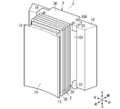
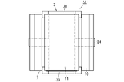
- the insulating member 3 has a pair of insulating plates 30, a connecting portion 32, and a fixing portion 33 (see FIGS. 1 to 3).
- Each of the pair of insulating plates 30 is formed in a rectangular flat plate shape. However, the pair of insulating plates 30 are formed to have the same shape and size.
- the width dimension of the insulating plate 30 in the left-right direction (transverse direction) is larger than the width dimension of the teeth portion 11 in the left-right direction and smaller than the width dimension of the yoke portion 10 in the left-right direction.
- the width dimension in the front-rear direction (longitudinal direction) of the insulating member 3 is slightly smaller than the width dimension in the front-rear direction of the stator block 1 (see FIG. 1).
- One insulating plate 30 is arranged on the upper surface of the stator block 1 , and the other insulating plate 30 is arranged below the lower surface of the stator block 1 .
- the connecting part 32 is formed in a rectangular flat plate shape. One end (upper end) of the connecting portion 32 in the longitudinal direction is connected to the rear end of the insulating plate 30 arranged on the upper surface of the stator block 1 . The other end (lower end) of the connecting portion 32 in the longitudinal direction is connected to the rear end of the insulating plate 30 arranged under the lower surface of the stator block 1 . That is, the pair of insulating plates 30 are connected at their respective rear ends by connecting portions 32 (see FIGS. 2 and 3). Also, the connecting portion 32 is fitted into a groove portion 100 provided on the rear surface of the yoke portion 10 (see FIG. 3).
- the groove portion 100 is provided over the entire length of the yoke portion 10 in the vertical direction at the center of the rear surface of the yoke portion 10 in the horizontal direction. It is preferable that the pair of insulating plates 30 and the connecting portion 32 be integrally formed of an electrically insulating synthetic resin material.
- Each fixing portion 33 is formed in a hook shape when viewed in the horizontal direction (see FIG. 2).
- Each fixing portion 33 protrudes in the left-right direction from each of the left and right side surfaces of each insulating plate 30 from a position near the rear of the center of each insulating plate 30 in the front-rear direction.
- the tip portions of the two fixing portions 33 provided on the upper insulating plate 30 protrude downward.
- the tip portions of the two fixing portions 33 provided on the lower insulating plate 30 protrude upward (see FIG. 2).
- the coil 2 has windings 20 made of a conductor such as copper or copper alloy.
- the coil 2 is constructed by winding a wire 20 around the teeth 11 and a pair of insulating plates 30 .
- each of the pair of insulating plates 30 is formed wider than the tooth portion 11 .
- each insulating plate 30 is preferably formed wider than the tooth portion 11 by about 0.3 mm.
- the stator S1 can improve the space factor of the coil 2 as compared with the case where the winding 20 is wound around the tooth portion 11 via a bobbin.
- the number of turns of the coil 2 is 6 (6 turns) in FIGS. 1 to 3, it may be 7 (7 turns) or more.
- the windings 20 are covered with an insulator, the windings 20 can be wound in a double or more overlapping manner.
- the manufacturing method of the stator S1 (hereinafter abbreviated as manufacturing method) described below includes at least a first step, a second step, a third step and a fourth step.
- the first step is to attach the insulating member 3 to the stator block 1 .
- the connecting portion 32 is bent to widen the distance between the pair of insulating plates 30, and the insulating member 3 is covered from behind the yoke portion 10 of the stator block 1.
- the connecting portion 32 is fitted in the groove portion 100 on the rear surface of the yoke portion 10, and the tips of the pair of fixing portions 33 of each insulating plate 30 are aligned with the yoke portion. 10 are fitted into recesses 101 provided on the left and right ends of the front surface of the device 10 (see FIGS. 2 and 3).
- the insulating member 3 is attached to the stator block 1 in this way.
- the second step is a step of winding windings 20 around each of a plurality of stator blocks 1 to provide coils 2 .
- the winding operation of the winding 20 is performed by, for example, a winding machine.
- the winding 20 is wound around the tooth portion 11 so as to span the pair of insulating plates 30 .
- an insulation distance corresponding to the difference in width between the insulating plate 30 and the tooth portion 11 is secured between the left and right side surfaces of the tooth portion 11 not covered with the insulating member 3 and the winding 20 .
- the third step is a step of arranging a plurality of stator blocks 1 each provided with a coil 2 along the circumferential direction. As shown in FIG. 1, nine stator blocks 1 are arranged in a ring shape so that the left and right side surfaces of the yoke portions 10 are in contact with each other.
- the fourth step is to connect nine stator blocks 1 arranged along the circumferential direction. Specifically, the yoke portions 10 of two adjacent stator blocks 1 that are in contact with each other are joined by an appropriate method such as welding or adhesion. Then, the stator S1 is completed by combining all the nine stator blocks 1. As shown in FIG.
- the stator block 1 may be configured by stacking a plurality of plate members 4 in the thickness direction of the plate members 4 .
- Each of the plurality of plate members 4 is formed in the same shape as the upper surface of the stator block 1, as shown in FIG. Note that the groove 100 and the recess 101 of the yoke portion 10 are each configured by a notch 40 provided in the plate member 4 .
- the stator block 1 is constructed by connecting a plurality of plate members 4 stacked in the thickness direction to each other by an appropriate method such as welding or adhesion.
- the grooves 100 and recesses 101 of the yoke portion 10 can be formed by the notches 40 of the plate members 4 . Therefore, the groove 100 and the recess 101 can be formed more easily than when the groove 100 and the recess 101 are directly provided in the yoke portion 10 .
- each of the plurality of insulating members 3 further has an aligning portion 31 provided on each of the pair of insulating plates 30 to align the windings 20 .
- the alignment section 31 has a plurality of protrusions 311 provided on each of the pair of insulating plates 30 .
- the plurality of protrusions 311 are arranged at regular intervals along the front-rear direction of each insulating plate 30 .
- the plurality of protrusions 311 are provided so as to protrude leftward and rightward from the left side and right side of each insulating plate 30, respectively.
- the plurality of protrusions 311 are provided so as to protrude upward and downward from both left and right ends of the upper surface of the upper insulating plate 30 and the lower surface of the lower insulating plate 30, respectively. may be
- the alignment section 31 may have a plurality of recesses 310 provided in the pair of insulating plates 30, as shown in FIG.
- the alignment part 31 can accommodate and align the windings 20 in each of the plurality of recesses 310 .
- the windings 20 can be wound in alignment with the respective tooth portions 11 by the aligning portions 31 provided in the insulating member 3. .
- the stator S1 of Modification 1 can more easily align the windings 20 than when the aligning portion 31 is not provided, thereby suppressing displacement of the windings 20 .
- the insulating member 3 in Modification 2 does not have a connecting portion that connects the pair of insulating plates 30, as shown in FIGS. Further, the insulating member 3 in Modification 2 has a pair of protrusions 35 protruding downward from the lower surface of the upper insulating plate 30 and protruding upward from the upper surface of the lower insulating plate 30 instead of the hook-shaped fixing portion 33. It has a fixing portion consisting of a pair of projections 35 that connect to each other.
- Each projection 35 is formed in a cylindrical shape. Each projection 35 protrudes from the upper surface or the lower surface of the insulating plate 30 so as to be spaced apart in the front-rear direction. It should be noted that each projection 35 is preferably formed integrally with the insulating plate 30 with a synthetic resin material.
- the stator block 1 in Modification 2 has two holes 110 in each of the upper surface and the lower surface of the tooth portion 11 into which the pair of projections 35 of each insulating plate 30 are fitted.
- the inner peripheral surfaces of these holes 110 are formed in the shape of a cylindrical surface.
- a pair of projections 35 provided on the upper insulating plate 30 is fitted into each of the two holes 110 provided on the upper surface of the tooth portion 11 .
- a pair of protrusions 35 provided on the lower insulating plate 30 are fitted into each of the two holes 110 provided on the lower surface of the tooth portion 11 .
- each projection 35 is preferably fixed to the tooth portion 11 by an appropriate method such as welding or adhesion.
- the insulating plate 30 may be fixed to the stator block 1 by projecting ribs from the peripheral surfaces of the projections 35 and pressing the projections 35 into the holes 110 so as to crush the ribs.
- stator S1 of Modification 2 can be made compact by simplifying the structure of the plurality of insulating members 3 .
- stator block 1 of Modified Example 2 when the yoke portion 10 and the tooth portion 11 are separated as shown in FIG. may be coupled with the yoke portion 10 .
- the stator S ⁇ b>1 of Modified Example 3 is characterized by the structure of the plurality of insulating members 3 .
- Each of the plurality of insulating members 3 in Modification 3 further has a connecting portion 34 that connects adjacent connecting portions 32 (see FIGS. 12 to 14).
- the coupling portion 34 is formed in a prism shape.
- the coupling portions 34 protrude leftward and rightward from the center position in the vertical direction on both left and right side surfaces of the connecting portion 32 . Further, the front end surfaces (left side surface and right side surface) of the coupling portion 34 are inclined rearward so as to be flush with the left and right side surfaces of the yoke portion 10 (see FIG. 12).
- stator S1 of Modified Example 3 the connecting portions 34 of the adjacent insulating members 3 are connected by an appropriate method such as adhesion (see FIG. 15). That is, the stator S1 of Modification 3 can simplify the manufacturing process of the stator S1 as compared with the case where the yoke portions 10 of the adjacent stator blocks 1 are coupled to each other.
- the stator S ⁇ b>1 of Modification 4 is characterized by the structures of the plurality of stator blocks 1 and the insulating members 3 .
- the width dimension (the length dimension in the left-right direction) of the connecting portion 32 is larger than the width dimension (the width dimension in the left-right direction) of the teeth portion 11 of the stator block 1. It is made smaller (see FIG. 16). Further, in the stator S1 of Modification 4, the width dimension (width dimension in the left-right direction) of the groove portion 100 provided on the outer peripheral surface (rear surface) of the yoke portion 10 is smaller than the width dimension of the teeth portion 11, and the connecting portion 32 width dimension or more. Furthermore, in the stator S1 of Modified Example 4, the depth of the groove portion 100 (depth in the front-rear direction) is greater than or equal to the thickness of the connecting portion 32 (thickness in the front-rear direction).
- the width dimension of the coupling portion 32 and the width dimension of the groove portion 100 are smaller than the width dimension of the tooth portion 11, so that the magnetic flux passing through the stator block 1 is less susceptible to the coupling portion 32. .
- the depth of the groove portion 100 is greater than or equal to the thickness of the connecting portion 32 , so the connecting portion 32 does not protrude from the outer peripheral surface of the yoke portion 10 .
- the stator S1 of Modification 4 can be made smaller in the radial direction (the front-rear direction of the stator block 1).
- each insulating member 3 by connecting the pair of insulating plates 30 with the connecting portion 32, workability of mounting the insulating member 3 to the stator block 1 can be improved.
- the connecting portion 32 is arranged at a position facing the outer peripheral surface of the yoke portion 10 . Therefore, the influence of the connecting portion 32 on the gap (see FIG. 1) between the stator S1 and the rotor R1 can be eliminated.
- the stator (S1) according to the first aspect of the present disclosure includes a plurality of stator blocks (1) arranged along the circumferential direction and windings (20) on each of the plurality of stator blocks (1). a plurality of coils (2) provided by winding.
- a stator (S1) according to a first aspect includes a plurality of insulators for electrically insulating a stator block (1) and a coil (2) for each set of a plurality of stator blocks (1) and a plurality of coils (2).
- a member (3) is provided.
- Each of the plurality of stator blocks (1) has a yoke portion (10) located on the outermost periphery and teeth (11) protruding from the inner peripheral surface of the yoke portion (10).
- Each of the plurality of insulating members (3) has a pair of insulating plates (30) arranged at opposing positions with the teeth (11) interposed therebetween. A pair of insulating plates (30) are formed wider than the teeth (11).
- the stator (S1) according to the first aspect corresponds to the difference in width dimension between the insulating plate (30) and the teeth (11) between the windings (20) of the coil (2) and the teeth (11). A space (insulation distance) is formed. As a result, the stator (S1) according to the first aspect can improve the space factor of the coil (2).
- each of the plurality of insulating members (3) preferably further has a connecting portion (32) that connects the pair of insulating plates (30).
- the stator (S1) according to the second aspect can improve workability when attaching the insulating member (3) to the stator block (1).
- the stator (S1) according to the third aspect of the present disclosure can be realized by combining with the second aspect.
- the coupling portion (32) is arranged at a position facing the outer peripheral surface of the yoke portion (10).
- the connecting part (32) is not arranged between the stator block (1) and the rotor (R1), the gap between the stator (S1) and the rotor (R1) is Therefore, the influence of the connecting portion (32) can be eliminated.
- the stator (S1) according to the fourth aspect of the present disclosure can be realized in combination with the third aspect.
- the outer peripheral surface of the yoke portion (10) is provided with a groove portion (100) that engages with the connecting portion (32).
- stator (S1) In the stator (S1) according to the fourth aspect, at least part of the connecting portion (32) is fitted into the groove (100), so that the connecting portion (32) protrudes from the outer peripheral surface of the yoke portion (10). Projection dimensions can be reduced.
- the stator (S1) according to the fifth aspect of the present disclosure can be realized in combination with the fourth aspect.
- the width dimension along the circumferential direction of the connecting portion (32) is smaller than the width dimension along the circumferential direction of the teeth portion (11).
- the magnetic flux passing through the stator block (1) is less affected by the connecting portion (32).
- each of the plurality of insulating members (3) is fixed to one or more corresponding stator blocks (1) among the plurality of stator blocks (1). It is preferable to have a fixing part (33) of
- the stator (S1) according to the sixth aspect can easily fix the insulating member (3) to the stator block (1) by having the fixing portion (33).
- the stator (S1) according to the seventh aspect of the present disclosure can be realized in combination with the sixth aspect.
- the fixing portion (33) is formed in a hook shape and hooked on the yoke portion (10).
- the stator (S1) according to the seventh aspect can easily fix the fixing portion (33) to the yoke portion (10).
- the stator (S1) according to the eighth aspect of the present disclosure can be realized in combination with the seventh aspect.
- the yoke portion (10) preferably has a recess (101) for accommodating the fixing portion (33) at a portion on which the fixing portion (33) is hooked.
- the fixing part (33) is less likely to get in the way when the winding (20) is wound. can be planned.
- each of the plurality of stator blocks (1) is preferably configured by stacking a plurality of plate members (4) in the thickness direction of the plate members (4).
- the recesses (101) are preferably configured by notches (40) provided in a plurality of plates (4).
- stator (S1) according to the ninth aspect when the stator block (1) is configured as a laminate of a plurality of plate members (4), the recess (101) of the yoke portion (10) is replaced with the plate member (4). notch (40). Therefore, in the stator (S1) according to the twelfth aspect, the recesses (101) can be formed more easily than when the recesses (101) are provided directly in the yoke portion (10).
- the stator (S1) according to the tenth aspect of the present disclosure can be realized in combination with the sixth aspect.
- the fixing portions (protrusions 35) are configured to protrude from each of the pair of insulating plates (30) toward the tooth portions (11). It is preferable that the fixed portion is configured to fit into the hole (110) provided in the tooth portion (11).
- the stator (S1) according to the tenth aspect can easily fix the pair of insulating plates (30) to the teeth (11).
- each of the plurality of insulating members (3) further has a connecting portion (34) that connects adjacent connecting portions (32).
- the plurality of insulating members (3) can be easily connected together by the connecting portion (34).
- each of the plurality of insulating members (3) has an alignment portion (31) provided on each of the pair of insulating plates (30) for aligning the windings (20). Further, it is preferable to have.
- stator (S1) according to a twelfth aspect in a plurality of stator blocks (1), windings (20 ) can be aligned and wound.
- the stator (S1) according to the twelfth aspect can more easily align the windings (20) than in the case where the alignment part (31) is not provided. can be suppressed.
- the stator (S1) according to the thirteenth aspect of the present disclosure can be realized in combination with the twelfth aspect.
- the aligning part (31) has a plurality of recesses (310) provided in the pair of insulating plates (30), and winds around each of the plurality of recesses (310). It is preferred to accommodate and align the lines (20).
- the stator (S1) according to the thirteenth aspect can easily align the windings (20) by the aligning portion (31).
- a brushless motor (M1) according to a fourteenth aspect of the present disclosure includes a stator (S1) according to any one of the first to thirteenth aspects, and a rotor (R1) rotatably arranged inside the stator (S1). ) and
Landscapes
- Engineering & Computer Science (AREA)
- Power Engineering (AREA)
- Insulation, Fastening Of Motor, Generator Windings (AREA)
- Iron Core Of Rotating Electric Machines (AREA)
Priority Applications (4)
| Application Number | Priority Date | Filing Date | Title |
|---|---|---|---|
| US18/274,753 US12463475B2 (en) | 2021-02-15 | 2021-12-20 | Stator and brushless motor |
| CN202180091731.XA CN116964909A (zh) | 2021-02-15 | 2021-12-20 | 定子和无刷马达 |
| JP2022581213A JP7627899B2 (ja) | 2021-02-15 | 2021-12-20 | ステータ及びブラシレスモータ |
| EP21925836.5A EP4293877A4 (en) | 2021-02-15 | 2021-12-20 | STATOR AND BRUSHLESS MOTOR |
Applications Claiming Priority (2)
| Application Number | Priority Date | Filing Date | Title |
|---|---|---|---|
| JP2021022081 | 2021-02-15 | ||
| JP2021-022081 | 2021-02-15 |
Publications (1)
| Publication Number | Publication Date |
|---|---|
| WO2022172593A1 true WO2022172593A1 (ja) | 2022-08-18 |
Family
ID=82838681
Family Applications (1)
| Application Number | Title | Priority Date | Filing Date |
|---|---|---|---|
| PCT/JP2021/046970 Ceased WO2022172593A1 (ja) | 2021-02-15 | 2021-12-20 | ステータ及びブラシレスモータ |
Country Status (5)
| Country | Link |
|---|---|
| US (1) | US12463475B2 (https=) |
| EP (1) | EP4293877A4 (https=) |
| JP (1) | JP7627899B2 (https=) |
| CN (1) | CN116964909A (https=) |
| WO (1) | WO2022172593A1 (https=) |
Families Citing this family (1)
| Publication number | Priority date | Publication date | Assignee | Title |
|---|---|---|---|---|
| WO2022172593A1 (ja) * | 2021-02-15 | 2022-08-18 | パナソニックIpマネジメント株式会社 | ステータ及びブラシレスモータ |
Citations (12)
| Publication number | Priority date | Publication date | Assignee | Title |
|---|---|---|---|---|
| JP2003018780A (ja) * | 2001-07-03 | 2003-01-17 | Matsushita Electric Ind Co Ltd | 電動機 |
| JP2003111329A (ja) * | 2001-10-03 | 2003-04-11 | Mitsubishi Electric Corp | 回転電機の固定子 |
| JP2004357491A (ja) * | 2003-05-08 | 2004-12-16 | Asmo Co Ltd | 回転電機のステータ及びその製造方法 |
| JP2009044853A (ja) * | 2007-08-08 | 2009-02-26 | Nsk Ltd | 回転電動機のコイル機構 |
| JP2010114998A (ja) | 2008-11-06 | 2010-05-20 | Sumitomo Electric Ind Ltd | コイルユニットおよび電磁部品 |
| JP2011259614A (ja) * | 2010-06-09 | 2011-12-22 | Mitsubishi Electric Corp | 回転電機の固定子 |
| WO2012114508A1 (ja) * | 2011-02-25 | 2012-08-30 | 三菱電機株式会社 | 回転電機のステータ、およびその製造方法 |
| JP2013132110A (ja) * | 2011-12-20 | 2013-07-04 | Mitsubishi Electric Corp | 電動機の固定子及び絶縁シートの製造方法 |
| JP2014100016A (ja) * | 2012-11-15 | 2014-05-29 | Mitsubishi Electric Corp | 固定子 |
| JP2016201866A (ja) * | 2015-04-07 | 2016-12-01 | 三菱電機株式会社 | 固定子およびその固定子の鉄心に取り付けられた絶縁体の製造方法ならびにその固定子を備えた回転電機 |
| JP2017139838A (ja) * | 2016-02-01 | 2017-08-10 | 三菱電機株式会社 | 固定子およびその固定子を備えた回転電機 |
| WO2018235564A1 (ja) * | 2017-06-22 | 2018-12-27 | 日本電産株式会社 | ステータピース、ステータおよびモータ |
Family Cites Families (16)
| Publication number | Priority date | Publication date | Assignee | Title |
|---|---|---|---|---|
| US6946769B2 (en) | 2003-05-08 | 2005-09-20 | Asmo Co., Ltd. | Insulator and manufacturing method thereof, and stator for electric rotating machine |
| JP4998450B2 (ja) * | 2008-12-09 | 2012-08-15 | トヨタ自動車株式会社 | ステータの製造方法 |
| JP5343625B2 (ja) | 2009-03-02 | 2013-11-13 | 日産自動車株式会社 | 回転電機用インシュレーター及び回転電機用ステーター |
| JP5743768B2 (ja) | 2011-07-14 | 2015-07-01 | 三菱電機株式会社 | 回転電機の固定子 |
| JP5738385B2 (ja) * | 2013-11-18 | 2015-06-24 | 三菱電機株式会社 | 固定子およびその固定子を備えた回転電機 |
| JP2015133808A (ja) | 2014-01-10 | 2015-07-23 | アスモ株式会社 | インシュレータ及びステータ |
| JP6070603B2 (ja) * | 2014-03-04 | 2017-02-01 | トヨタ自動車株式会社 | ステータの製造方法 |
| JP6303978B2 (ja) | 2014-10-27 | 2018-04-04 | トヨタ自動車株式会社 | 回転電機のステータ |
| KR102294928B1 (ko) * | 2015-01-06 | 2021-08-31 | 엘지이노텍 주식회사 | 스테이터 코어 및 이를 포함하는 모터 |
| JP6698865B2 (ja) * | 2016-11-16 | 2020-05-27 | 三菱電機株式会社 | 回転電機 |
| EP3687041B1 (en) * | 2017-09-20 | 2022-09-07 | Panasonic Intellectual Property Management Co., Ltd. | Insulator, and stator and motor comprising same |
| KR102566024B1 (ko) | 2018-05-23 | 2023-08-11 | 현대모비스 주식회사 | 차량용 구동모터의 보빈 |
| US12101006B2 (en) * | 2020-01-06 | 2024-09-24 | Lg Innotek Co., Ltd. | Motor, and method for manufacturing stator provided in motor |
| WO2021205708A1 (ja) | 2020-04-07 | 2021-10-14 | 日立Astemo株式会社 | 回転電機の固定子 |
| EP4293878A4 (en) * | 2021-02-15 | 2024-08-14 | Panasonic Intellectual Property Management Co., Ltd. | STATOR, STATOR MANUFACTURING METHOD AND BRUSHLESS MOTOR |
| WO2022172593A1 (ja) * | 2021-02-15 | 2022-08-18 | パナソニックIpマネジメント株式会社 | ステータ及びブラシレスモータ |
-
2021
- 2021-12-20 WO PCT/JP2021/046970 patent/WO2022172593A1/ja not_active Ceased
- 2021-12-20 EP EP21925836.5A patent/EP4293877A4/en active Pending
- 2021-12-20 JP JP2022581213A patent/JP7627899B2/ja active Active
- 2021-12-20 CN CN202180091731.XA patent/CN116964909A/zh active Pending
- 2021-12-20 US US18/274,753 patent/US12463475B2/en active Active
Patent Citations (12)
| Publication number | Priority date | Publication date | Assignee | Title |
|---|---|---|---|---|
| JP2003018780A (ja) * | 2001-07-03 | 2003-01-17 | Matsushita Electric Ind Co Ltd | 電動機 |
| JP2003111329A (ja) * | 2001-10-03 | 2003-04-11 | Mitsubishi Electric Corp | 回転電機の固定子 |
| JP2004357491A (ja) * | 2003-05-08 | 2004-12-16 | Asmo Co Ltd | 回転電機のステータ及びその製造方法 |
| JP2009044853A (ja) * | 2007-08-08 | 2009-02-26 | Nsk Ltd | 回転電動機のコイル機構 |
| JP2010114998A (ja) | 2008-11-06 | 2010-05-20 | Sumitomo Electric Ind Ltd | コイルユニットおよび電磁部品 |
| JP2011259614A (ja) * | 2010-06-09 | 2011-12-22 | Mitsubishi Electric Corp | 回転電機の固定子 |
| WO2012114508A1 (ja) * | 2011-02-25 | 2012-08-30 | 三菱電機株式会社 | 回転電機のステータ、およびその製造方法 |
| JP2013132110A (ja) * | 2011-12-20 | 2013-07-04 | Mitsubishi Electric Corp | 電動機の固定子及び絶縁シートの製造方法 |
| JP2014100016A (ja) * | 2012-11-15 | 2014-05-29 | Mitsubishi Electric Corp | 固定子 |
| JP2016201866A (ja) * | 2015-04-07 | 2016-12-01 | 三菱電機株式会社 | 固定子およびその固定子の鉄心に取り付けられた絶縁体の製造方法ならびにその固定子を備えた回転電機 |
| JP2017139838A (ja) * | 2016-02-01 | 2017-08-10 | 三菱電機株式会社 | 固定子およびその固定子を備えた回転電機 |
| WO2018235564A1 (ja) * | 2017-06-22 | 2018-12-27 | 日本電産株式会社 | ステータピース、ステータおよびモータ |
Non-Patent Citations (1)
| Title |
|---|
| See also references of EP4293877A4 |
Also Published As
| Publication number | Publication date |
|---|---|
| US20240097511A1 (en) | 2024-03-21 |
| JPWO2022172593A1 (https=) | 2022-08-18 |
| US12463475B2 (en) | 2025-11-04 |
| EP4293877A1 (en) | 2023-12-20 |
| CN116964909A (zh) | 2023-10-27 |
| EP4293877A4 (en) | 2024-08-14 |
| JP7627899B2 (ja) | 2025-02-07 |
Similar Documents
| Publication | Publication Date | Title |
|---|---|---|
| WO2015159329A1 (ja) | アキシャルエアギャップ型回転電機 | |
| JP7627900B2 (ja) | ステータ、ステータの製造方法、及びブラシレスモータ | |
| CN111245164A (zh) | 旋转电机及其制造方法 | |
| CN103855819B (zh) | 电动致动器 | |
| JP5181627B2 (ja) | 回転電機および回転電機の製造方法 | |
| EP1341288B1 (en) | Electric rotary machine | |
| CN107005112A (zh) | 旋转电机 | |
| JP2011193564A (ja) | アキシャルギャップ型回転電機用ステータとその製造方法 | |
| WO2022172593A1 (ja) | ステータ及びブラシレスモータ | |
| JP4411950B2 (ja) | 電動機固定子、その製造方法、およびその固定子を用いた永久磁石形電動機 | |
| JP6429400B2 (ja) | ステータコア、ステータ及び回転電機 | |
| US20240128809A1 (en) | Stator and brushless motor | |
| JP2020150753A (ja) | ステータ及びブラシレスモータ | |
| JP7104340B2 (ja) | 回転電機 | |
| JP2023122730A (ja) | コアユニット、コアユニット組立体および回転電機 | |
| JP2018207616A (ja) | モータ | |
| JP2023053649A (ja) | 回転電機のステータ | |
| JP2018207617A (ja) | モータ | |
| JP2023072907A (ja) | ステータ | |
| JP4476778B2 (ja) | リニアモータ | |
| JP2009065800A (ja) | ステータの中点連結構造 | |
| CN115552769A (zh) | 旋转电机的定子、旋转电机、旋转电机的定子的制造方法及旋转电机的制造方法 | |
| JP2018207615A (ja) | モータ | |
| WO2018207315A1 (ja) | 回転電機の電機子鉄心 | |
| JP2018207618A (ja) | モータ |
Legal Events
| Date | Code | Title | Description |
|---|---|---|---|
| 121 | Ep: the epo has been informed by wipo that ep was designated in this application |
Ref document number: 21925836 Country of ref document: EP Kind code of ref document: A1 |
|
| WWE | Wipo information: entry into national phase |
Ref document number: 202180091731.X Country of ref document: CN |
|
| WWE | Wipo information: entry into national phase |
Ref document number: 18274753 Country of ref document: US |
|
| WWE | Wipo information: entry into national phase |
Ref document number: 2022581213 Country of ref document: JP |
|
| WWE | Wipo information: entry into national phase |
Ref document number: 2021925836 Country of ref document: EP |
|
| NENP | Non-entry into the national phase |
Ref country code: DE |
|
| ENP | Entry into the national phase |
Ref document number: 2021925836 Country of ref document: EP Effective date: 20230915 |
|
| WWG | Wipo information: grant in national office |
Ref document number: 18274753 Country of ref document: US |