WO2022172324A1 - 表示ユニット及び表示装置 - Google Patents
表示ユニット及び表示装置 Download PDFInfo
- Publication number
- WO2022172324A1 WO2022172324A1 PCT/JP2021/004773 JP2021004773W WO2022172324A1 WO 2022172324 A1 WO2022172324 A1 WO 2022172324A1 JP 2021004773 W JP2021004773 W JP 2021004773W WO 2022172324 A1 WO2022172324 A1 WO 2022172324A1
- Authority
- WO
- WIPO (PCT)
- Prior art keywords
- light emitting
- emitting element
- display unit
- light
- height
- Prior art date
- Legal status (The legal status is an assumption and is not a legal conclusion. Google has not performed a legal analysis and makes no representation as to the accuracy of the status listed.)
- Ceased
Links
Images


Classifications
-
- G—PHYSICS
- G09—EDUCATION; CRYPTOGRAPHY; DISPLAY; ADVERTISING; SEALS
- G09F—DISPLAYING; ADVERTISING; SIGNS; LABELS OR NAME-PLATES; SEALS
- G09F9/00—Indicating arrangements for variable information in which the information is built-up on a support by selection or combination of individual elements
- G09F9/30—Indicating arrangements for variable information in which the information is built-up on a support by selection or combination of individual elements in which the desired character or characters are formed by combining individual elements
- G09F9/302—Indicating arrangements for variable information in which the information is built-up on a support by selection or combination of individual elements in which the desired character or characters are formed by combining individual elements characterised by the form or geometrical disposition of the individual elements
-
- G—PHYSICS
- G09—EDUCATION; CRYPTOGRAPHY; DISPLAY; ADVERTISING; SEALS
- G09F—DISPLAYING; ADVERTISING; SIGNS; LABELS OR NAME-PLATES; SEALS
- G09F9/00—Indicating arrangements for variable information in which the information is built-up on a support by selection or combination of individual elements
- G09F9/30—Indicating arrangements for variable information in which the information is built-up on a support by selection or combination of individual elements in which the desired character or characters are formed by combining individual elements
- G09F9/33—Indicating arrangements for variable information in which the information is built-up on a support by selection or combination of individual elements in which the desired character or characters are formed by combining individual elements being semiconductor devices, e.g. diodes
Definitions
- the present disclosure relates to display units and display devices.
- a display device in which a plurality of light emitting diode (LED: Light Emitting Diode) elements are arranged on a substrate is known.
- LED Light Emitting Diode
- Patent Document 1 among four pixels of a basic lattice (square lattice) composed of four pixels of 2 ⁇ 2, at least one pixel is assigned a 3-in-1 light emitting element including three primary colors of RGB, and the remaining pixels are monochromatic.
- An image display device is disclosed in which basic lattices of patterns in which light emitting elements are allocated are repeatedly arranged in a lattice.
- Patent Document 1 a light emitting element is assigned to each of four lattice points of a square lattice. Therefore, if a large-sized, high-definition image display device is manufactured using the arrangement of the light-emitting elements of Patent Document 1, the number of light-emitting elements is extremely large. This increases the manufacturing cost of the image display device.
- the present disclosure has been made in view of the above circumstances, and aims to provide a display unit and a display device that can reduce the number of light-emitting elements to reduce manufacturing costs while suppressing deterioration in image quality.
- the display unit includes a substrate, and a plurality of pixel groups arranged on the mounting surface of the substrate and having pixels at three lattice points of a square lattice and no pixels at the remaining lattice points of the square lattice.
- the pixel group includes, as pixels, a first light-emitting element positioned at one of the lattice points of the square lattice and two lattice points of the square lattice adjacent to the lattice point of the square lattice where the first light-emitting element is positioned. and a second light emitting element.
- One of the first light emitting element and the second light emitting element can independently emit red light, green light and blue light. The other of the first light emitting element and the second light emitting element only emits white light.
- the light-emitting element is not arranged at the remaining lattice point of the square lattice, deterioration of image quality can be suppressed, and the number of light-emitting elements can be reduced to reduce the manufacturing cost.
- FIG. 4 is a diagram showing the resolution of the display unit according to Embodiment 1
- FIG. 11 is a diagram showing resolution of a display unit according to a comparative example
- Schematic diagram showing the front of the display unit according to the second embodiment is a diagram showing the resolution of the display unit according to the second embodiment
- Schematic diagram showing the front of a display unit according to Embodiment 3 The perspective view which shows the 1st eaves part which concerns on Embodiment 3.
- Sectional view of the display unit shown in FIG. 9 taken along line FF Schematic diagram showing the front of the display unit according to the fourth embodiment.
- Cross-sectional view of the display unit shown in FIG. 14 taken along line JJ Cross-sectional view of the display unit shown in FIG. 14 taken along line KK Schematic diagram showing the front of the display unit according to the fifth embodiment.
- FIG. 5 Schematic diagram showing a mask plate according to Embodiment 5 Schematic diagram showing sizes of an opening and a first light emitting element according to Embodiment 5 Schematic diagram showing sizes of an opening and a second light emitting element according to Embodiment 5 The perspective view which shows the display apparatus which concerns on Embodiment 6. Schematic diagram showing a second light emitting element according to a modification
- FIG. 1 A display unit 10 according to the first embodiment will be described with reference to FIGS. 1 to 5.
- FIG. For ease of understanding, it is assumed that the display unit 10 is installed outdoors with the front surface of the display unit 10 perpendicular to the ground, and the vertical direction is the Y-axis direction parallel to the ground and the front surface of the display unit 10.
- a direction perpendicular to the X-axis direction and the Y-axis direction is defined as a Z-axis direction.
- the +Y direction faces upward when the display unit 10 is installed, the +Y direction is also described as upward or vertically upward.
- the display unit 10 includes a substrate 20 and a plurality of pixel groups 30 arranged on a mounting surface 20a of the substrate 20, as shown in FIG.
- the pixel group 30 includes, as pixels, a first light-emitting element 32 positioned at a lattice point A of a square lattice 30a, and two lattices of the square lattice 30a adjacent to the lattice point A of the square lattice 30a at which the first light-emitting element 32 is positioned. and second light emitting elements 34 positioned at points B and C, respectively.
- the first light emitting element 32 can independently emit red light, green light, and blue light.
- the second light emitting element only emits white light.
- being able to independently emit red, green, and blue light means that the emitted light intensities of red, green, and blue light can be adjusted independently.
- the display unit 10 is installed outdoors such as at a stadium or on the wall of a building.
- the substrate 20 has a mounting surface 20a on which the pixel group 30 is arranged.
- the substrate 20 is made of insulating resin.
- the insulating resin is, for example, epoxy resin mixed with glass fiber.
- the substrate 20 includes wiring and a drive IC (IC: Integrated Circuit), which are not shown.
- the driving IC of the substrate 20 supplies power to the first light emitting element 32 and the second light emitting element 34 through the wiring of the substrate 20 to drive the first light emitting element 32 and the second light emitting element 34 .
- Power is supplied to the driving ICs of the substrate 20 from a power source external to the display unit 10 .
- the pixel group 30 has pixels at three grid points A, B, and C of the square grid 30a, and has no pixels at the remaining grid point D of the square grid 30a.
- the centers of the pixels are located at the grid points A, B, and C, respectively.
- the pixel group 30 is arranged in a matrix on the mounting surface 20a of the substrate 20 so that the side formed by the lattice points A and B faces upward, that is, in the +Y direction.
- the pixel groups 30 are arranged at regular intervals of x1 in the X direction and y1 in the Y direction.
- the interval x1 and the interval y1 correspond to the pixel pitch of the display unit 10 or the pixel group 30. Also, since the lattice points A to D are lattice points of the square lattice 30a, the interval x1 and the interval y1 are equal.
- the pixel group 30 has, as pixels, first light emitting elements 32 mounted on the mounting surface 20a of the substrate 20 at lattice points A of the square lattice 30a.
- the pixel group 30 includes second light emitting elements 34 mounted as pixels on the mounting surface 20a of the substrate 20 at lattice points B and C of the two square lattices 30a adjacent to the lattice point A of the square lattice 30a.
- no light emitting element is arranged at the lattice point D of the square lattice 30a.
- the first light emitting elements 32 of the pixel group 30 can independently emit red light, green light, and blue light from a flat surface arranged on the front side of the display unit 10 .
- the first light emitting element 32 is, for example, a 3-in-1 type surface-mounted LED element.
- the second light emitting elements 34 of the pixel group 30 emit only white light from the flat surface arranged on the front side of the display unit 10 .
- the second light emitting element 34 is, for example, a surface-mounted LED element that emits only white light.
- the flat surface of the first light emitting element 32 and the second light emitting element 34 arranged on the front side of the display unit 10 is the top surface
- the mounting surface 20a of the first light emitting element 32 and the second light emitting element 34 is the mounting surface 20a.
- the vertical plane be the side.
- the second light emitting element 34 that emits only white light ensures the resolution of the display unit 10 .
- the first light emitting element 32 which can independently emit red light, green light, and blue light, plays a role of expressing colors.
- the X-direction sampling frequency and the Y-direction sampling frequency of the image signal input to the display unit 10 correspond to the X-direction pixel pitch x1 and the Y-direction pixel pitch y1, respectively.
- the resolution due to the arrangement of the first light emitting elements 32 will be described.
- the maximum frequency of the image signal that can be restored by the arrangement of the first light emitting elements 32 corresponds to the resolution of the arrangement of the first light emitting elements 32 .
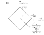
- resolution is expressed using the XY plane, as shown in FIG.
- the resolution due to the arrangement of the first light emitting elements 32 is represented by the area of a rectangle R1.
- FIG. 4 shows that the wider the square area, the higher the resolution.
- the second light emitting elements 34 are arranged at a pitch of ⁇ 2 ⁇ x1 in the direction of 45° with respect to the X-axis direction, or with a pitch of ⁇ 2 ⁇ y1 in the direction of 45° with respect to the Y-axis direction.
- the maximum frequency of an image signal that can be restored by the arrangement of the second light emitting elements 34 is 1/(2 ⁇ 2 ⁇ x1) or 1/(2 ⁇ 2 ⁇ y1).
- the resolution due to the arrangement of the second light emitting elements 34 is represented by the area of a rectangle R2.
- the resolution of the display unit of the comparative example will be explained.
- the first light emitting elements 32 are arranged at the diagonal grid points A and D, respectively, and the second light emitting elements 34 are arranged at the diagonal grid points B and C, respectively.
- a group of pixels corresponds to a pixel group obtained by adding the first light emitting element 32 to the grid point D of the pixel group 30 .
- the display unit of the comparative example is similar to the display unit 10 except for the pixel groups.
- the first light emitting element 32 has a pitch of ⁇ 2 ⁇ x1 in the direction of 45° with respect to the X axis direction, or They are arranged at a pitch of ⁇ 2 ⁇ y1 in the direction of 45°. Therefore, in the comparative example, the maximum frequency of the image signal that can be restored by the arrangement of the first light emitting elements 32 is, as shown in FIG. , 1/(2 ⁇ 2 ⁇ x1) or 1/(2 ⁇ 2 ⁇ y1).
- the maximum frequency of the image signal that can be restored by the arrangement of the first light emitting elements 32 in the comparative example is 1/(2 ⁇ x1) in the X direction and 1/(2 ⁇ y1) in the Y direction.
- the maximum frequency of the image signal that can be restored by the arrangement of the second light emitting elements 34 of the comparative example is the same as the maximum frequency of the image signal that can be restored by the arrangement of the first light emitting elements 32 of the comparative example.
- the resolution of the first light emitting element 32 that plays a role of expressing the color of the display unit 10 is lower than that of the first light emitting element 32 of the display unit of the comparative example. lower than the resolution.
- the reduction in resolution of the first light emitting element 32 of the display unit 10 has little effect on the image quality perceived by the observer. do not do. That is, in the display unit 10, degradation of image quality is sufficiently suppressed.
- the number of the first light emitting elements 32 in the display unit 10 is the same as the number of the first light emitting elements in the display unit of the comparative example. Very few compared to the number of 32. Therefore, in the display unit 10, the manufacturing cost can be reduced by reducing the number of light emitting elements. Since the display unit 10 can emit red light, green light, and blue light independently, and the number of expensive first light emitting elements 32 is small, the manufacturing cost can be further reduced.
- the first light emitting element 32 is arranged at the lattice point A of the square lattice 30a, and the second light emitting element 34 is arranged at each of the lattice points B and C of the square lattice 30a. Since no light-emitting element is arranged at the lattice point D of 30a, the number of light-emitting elements can be reduced and the manufacturing cost can be reduced. Furthermore, deterioration of the image quality of the display unit 10 can be suppressed.
- the display unit 11 according to the second embodiment will be described with reference to FIGS. 6 to 8.
- FIG. 1 the pixel groups 30 are arranged in a matrix on the mounting surface 20a of the substrate 20 so that the sides formed by the lattice points A and B of the square lattice 30a face the +Y direction.
- the pixel group 30 may be arranged on the mounting surface 20a of the substrate 20 with the sides of the square lattice 30a inclined at 45° with respect to the Y-axis direction, that is, the vertical direction.
- the display unit 11 includes a substrate 20 and a plurality of pixel groups 30 arranged on the mounting surface 20a of the substrate 20, like the display unit 10 of the first embodiment.
- the pixel group 30 of the display unit 11 is arranged in a zigzag arrangement on the mounting surface 20a of the substrate 20 with the sides of the square lattice 30a inclined by 45° with respect to the Y-axis direction and the lattice points A directed in the +Y direction.
- the arrangement of the pixel group 30 of the display unit 11 corresponds to the arrangement of the pixel group 30 of the display unit 10 rotated counterclockwise by 45° in plan view.
- Display unit 11 is similar to display unit 10 except for the arrangement of pixel group 30 .
- the first light emitting elements 32 of the display unit 11 are arranged at a pitch of 2 ⁇ y1 in the direction of 45° with respect to the Y-axis direction. Therefore, according to the sampling theorem, the maximum frequency of the image signal that can be restored by the arrangement of the first light emitting elements 32 of the display unit 11 is 1/(4 ⁇ y1), 1/(2 ⁇ 2 ⁇ x1) in the X direction and 1/(2 ⁇ 2 ⁇ y1) in the Y direction.
- the resolution due to the arrangement of the first light emitting elements 32 of the display unit 11 is represented by the area of a rectangle R3.
- the second light emitting elements 34 of the display unit 11 are arranged at a pitch of ⁇ 2 ⁇ x1 in the X direction and at a pitch of ⁇ 2 ⁇ y1 in the Y direction. Therefore, according to the sampling theorem, the maximum frequency of the image signal that can be restored by the arrangement of the second light emitting elements 34 of the display unit 11 is 1/(2 ⁇ 2 ⁇ x1) in the X direction, as shown in FIG. , 1/(2 ⁇ 2 ⁇ y1) in the Y direction.
- the resolution due to the arrangement of the second light emitting elements 34 of the display unit 11 is represented by the area of a rectangle R4.
- the resolution of the first light emitting elements 32 that play the role of expressing the colors of the display unit 11 is lower than the resolution of the first light emitting elements 32 of the display unit of the comparative example.
- the decrease in resolution of the first light emitting element 32 of the display unit 11 has little effect on the image quality perceived by the observer. do not do.
- the number of the first light emitting elements 32 of the display unit 11 is much smaller than the number of the first light emitting elements 32 of the display unit of the comparative example. Therefore, in the display unit 11, deterioration of image quality can be suppressed, and the manufacturing cost can be reduced by reducing the number of light emitting elements.
- the first light emitting element 32 is arranged at the lattice point A of the square lattice 30a
- the second light emitting element 34 is arranged at each of the lattice points B and C of the square lattice 30a. Since the light-emitting element is not arranged at the grid point D of the grid 30a, it is possible to suppress the deterioration of the image quality and reduce the manufacturing cost. Further, in the display unit 11, as shown in FIG. 6, the same kind of light-emitting elements are arranged in the X-axis direction and the Y-axis direction, so that the display unit 11 can be viewed clearly even by an observer who is positioned away from the front. display can be realized.
- the display unit 12 includes a substrate 20 and a plurality of pixel groups 30 arranged on the mounting surface 20a of the substrate 20, like the display unit 10 of the first embodiment.
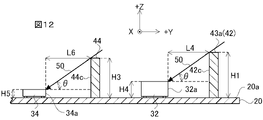
- the display unit 12 further includes a first canopy portion 42 and a second canopy portion 44 that block external light 50 .
- the external light 50 means light incident on the display unit 12 from the surroundings of the display unit 12, including sunlight and lighting. Blocking the external light 50 means suppressing the incidence of the external light 50 on the mounting surface 20 a of the first light emitting element 32 , the second light emitting element 34 , and the substrate 20 .
- the substrate 20 and pixel group 30 of the display unit 12 are similar to the substrate 20 and pixel group 30 of the display unit 10 .
- the first canopy part 42 is a black plate extending in the X-axis direction.
- the first eaves portion 42 is made of, for example, black resin by injection molding.
- the first eaves portion 42 is provided on the mounting surface 20 a of the substrate 20 .
- the first eaves portion 42 is fixed to the mounting surface 20a of the substrate 20 by, for example, screwing from the surface facing the mounting surface 20a of the substrate 20 .
- the first canopy portion 42 is vertically above the row of the first light emitting elements 32 and the second light emitting elements 34 extending in the X-axis direction, that is, the first light emitting elements 32 extending in the X-axis direction. It is arranged on the +Y direction side of the row of the second light emitting elements 34 .
- the first canopy part 42 has a step on the upper surface 42a with different heights from the mounting surface 20a of the substrate 20 to the upper end.
- the length L2 of the first eaves portion 42 in the X-axis direction is equal to the length L1 of the substrate 20 in the X-axis direction.
- the length D1 of the first eaves portion 42 in the Y-axis direction is set narrower than the interval y1 of the square lattice 30a. Heights H1 and H2 from the mounting surface 20a of the first eaves portion 42 to the upper end will be described later.
- the height from the mounting surface 20a of the first eaves portion 42 to the upper end indicates the length of the first eaves portion 42 in the Z-axis direction.
- the surface of the first eaves portion 42 arranged on the front side of the display unit 12 is the upper surface 42a, and the surface perpendicular to the mounting surface 20a of the first eaves portion 42 is the side surface.
- the second eaves portion 44 is a black plate extending in the X-axis direction, as shown in FIG.
- the second eaves portion 44 is made of, for example, black resin by injection molding.
- the second eaves portion 44 is provided on the mounting surface 20 a of the substrate 20 by being screwed from the surface facing the mounting surface 20 a of the substrate 20 .
- the second eaves portion 44 is vertically above the row of the second light emitting elements 34 extending in the X-axis direction, that is, on the +Y direction side of the row of the second light emitting elements 34 extending in the X-axis direction. placed.
- the length L3 of the second eaves portion 44 in the X-axis direction is equal to the length L1 of the substrate 20 in the X-axis direction.
- the length D2 of the second eaves portion 44 in the Y-axis direction is set narrower than the interval y1 of the square lattice 30a.
- the height H3 from the mounting surface 20a of the substrate 20 to the upper end of the second eaves portion 44 will be described later.
- a height H3 from the mounting surface 20a of the substrate 20 to the upper end of the second eaves portion 44 indicates the length of the second eaves portion 44 in the Z-axis direction.
- the surface of the second eaves portion 44 that is arranged on the front side of the display unit 12 is the upper surface, and the surface perpendicular to the mounting surface 20a of the second eaves portion 44 is the side surface.
- the first eaves portion 42 and the second eaves portion 44 are arranged at regular intervals in the Y-axis direction.
- the heights H1 and H2 of the first canopy portion 42 will be described. In this embodiment, it is assumed that the height H4 from the mounting surface 20a of the substrate 20 of the first light emitting element 32 to the upper end is higher than the height H5 from the mounting surface 20a of the substrate 20 of the second light emitting element 34 to the upper end. do.
- a height H4 from the mounting surface 20a of the substrate 20 to the upper end of the first light emitting element 32 indicates the length of the first light emitting element 32 in the Z-axis direction.
- a height H5 from the mounting surface 20a of the substrate 20 to the upper end of the second light emitting element 34 indicates the length of the second light emitting element 34 in the Z-axis direction.
- the high portion 43a from the mounting surface 20a to the upper end of the first canopy portion 42 is positioned vertically above the first light emitting element 32 when the display unit 12 is installed.
- a portion 43b of the first canopy portion 42 having a low height from the mounting surface 20a to the upper end is positioned vertically above the second light emitting element 34 when the display unit 12 is installed.
- the height H3 of the second eaves portion 44 is set according to the height H5 of the second light emitting element 34 and the distance between the second light emitting element 34 and the second eaves portion 44, as shown in FIG. .
- the height H4 of the first light emitting element 32 is higher than the height H5 of the second light emitting element 34. As shown in FIG.
- the height H1 of the portion 43a of the first eaves portion 42 is equal to the height H2 of the portion 43b of the first eaves portion 42 or the height H3 of the second eaves portion 44. is set higher by the difference between the height H4 of the first light emitting element 32 and the height H5 of the second light emitting element 34.
- the heights H1 and H2 of the first eaves portion 42 and the height H3 of the second eaves portion 44 are combined with the height H4 of the first light emitting element 32 and the height H5 of the second light emitting element 34 It is set according to the distance L4 between the first light emitting element 32 and the first eaves portion 42 and the distances L5 and L6 between the second light emitting element 34 and the first eaves portion 42 or the second eaves portion 44 .
- the outside light 50 incident on the mounting surface 20 a of the first light emitting element 32 , the second light emitting element 34 , and the substrate 20 can be uniformly blocked over the entire display unit 12 .
- the display unit 12 can realize an even display. Furthermore, the heights H1 and H2 of the first eaves portion 42 and the height H3 of the second eaves portion 44 are set to heights suitable for the height H4 of the first light emitting element 32 and the height H5 of the second light emitting element 34, respectively. Therefore, the display unit 12 can more effectively suppress the reflection of the external light 50 by the first light emitting element 32 and the second light emitting element 34, and realize high-contrast display.
- the display unit 12 has a height corresponding to the height H4 of the first light emitting element 32, the height H5 of the second light emitting element 34, and the distance from the first light emitting element 32 or the second light emitting element 34. Since the first eaves portion 42 and the second eaves portion 44 are provided, the outside light 50 is uniformly blocked, and a uniform display can be realized. Furthermore, the display unit 12 can realize high-contrast display. As with the display unit 10 of the first embodiment, the display unit 12 can suppress deterioration in image quality and reduce manufacturing costs.
- the display unit 13 includes a substrate 20 and a plurality of pixel groups 30 arranged on the mounting surface 20a of the substrate 20, like the display unit 11 of the second embodiment.
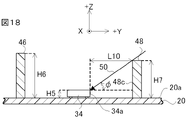
- the display unit 13 also includes a third canopy portion 46 and a fourth canopy portion 48 that block external light 50 on the mounting surface 20 a of the substrate 20 .
- the substrate 20 and pixel group 30 of the display unit 13 are similar to the substrate 20 and pixel group 30 of the display unit 11 .
- the surface of the third eaves portion 46 and the fourth eaves portion 48 arranged on the front side of the display unit 13 is perpendicular to the upper surface and the mounting surface 20a of the third eaves portion 46 and the fourth eaves portion 48. side.
- the height H6 from the mounting surface 20a of the substrate 20 to the upper end of the third eaves portion 46 is the length of the third eaves portion 46 in the Z-axis direction.
- the height H7 up to this point refers to the length of the fourth eaves portion 48 in the Z-axis direction.
- the third eaves portion 46 is a black plate extending in the X-axis direction, as shown in FIG. 16, the fourth canopy portion 48 is a black plate extending in the X-axis direction.
- the third eaves portion 46 and the fourth eaves portion 48 are made of black resin by injection molding, similarly to the second eaves portion 44 .
- the third canopy portion 46 is arranged vertically above the row of the first light emitting elements 32 extending in the X-axis direction in a state where the display unit 13 is installed.
- the fourth canopy portion 48 is arranged vertically above the row of the second light emitting elements 34 extending in the X-axis direction in a state where the display unit 13 is installed.
- the third eaves portion 46 and the fourth eaves portion 48 are provided on the mounting surface 20a of the substrate 20 by being screwed from the surface facing the mounting surface 20a of the substrate 20. be done.
- the length L7 of the third eaves portion 46 in the X-axis direction and the length L8 of the fourth eaves portion 48 in the X-axis direction are equal to the length L1 of the substrate 20 in the X-axis direction. Further, the length D3 of the third eaves portion 46 in the Y-axis direction and the length D4 of the fourth eaves portion 48 in the Y-axis direction are set narrower than the interval y1 of the square lattice 30a. The height H6 of the third eaves portion 46 and the height H7 of the fourth eaves portion 48 will be described later.
- the height H7 of the fourth canopy portion 48 is set according to the height H5 of the second light emitting element 34 and the distance between the second light emitting element 34 and the fourth canopy portion 48, as shown in FIG. .
- the height H4 of the first light emitting element 32 is higher than the height H5 of the second light emitting element 34 . Therefore, if the distance L9 and the distance L10 are equal, the height H6 of the third eaves portion 46 is greater than the height H7 of the fourth eaves portion 48 between the height H4 of the first light emitting element 32 and the second light emitting element 34. It is set higher by the difference from the height H5.
- the height H6 of the third eaves portion 46 and the height H7 of the fourth eaves portion 48 are equal to the height H4 of the first light emitting element 32 and the height H5 of the second light emitting element 34, and the height H4 of the first light emitting element 32 or the height H5 of the second light emitting element 34 Since the height is set according to the distance from the light emitting element 34, the display unit 13 can realize a uniform display like the display unit 12 of the third embodiment. Further, the display unit 13 can realize a high-contrast display like the display unit 12 of the third embodiment.
- the display unit 13 does not have a rough feeling. It is possible to realize a smooth display without
- the display unit 13 can evenly block outside light and realize a uniform display.
- the display unit 13 can realize high-contrast display.
- the display unit 13 can realize a smooth display without feeling rough.
- the display unit 13 can suppress deterioration in image quality and reduce manufacturing costs.
- the display unit 14 includes a substrate 20 and a plurality of pixel groups 30 arranged on the mounting surface 20a of the substrate 20, like the display unit 11 of the second embodiment.
- the display unit 14 further includes a mask plate 60 that blocks external light 50 .
- the mask plate 60 has a plurality of openings 62 and 64 into which the first light emitting elements 32 and the second light emitting elements 34 are respectively inserted.
- the substrate 20 and pixel group 30 of the display unit 14 are similar to the substrate 20 and pixel group 30 of the display unit 11 .
- the mask plate 60 is a black plate.
- the mask plate 60 is made of, for example, black resin by injection molding.
- the length L11 of the mask plate 60 in the X-axis direction is equal to the length L1 of the substrate 20 in the X-axis direction
- the length L12 of the mask plate 60 in the Y-axis direction is equal to the length L12 of the substrate 20 in the X-axis direction. is equal to the length L13 of
- the mask plate 60 has an opening 62 at a position where the first light emitting element 32 is mounted on the mounting surface 20a of the substrate 20. Also, the mask plate 60 has an opening 64 at a position where the second light emitting element 34 is mounted on the mounting surface 20 a of the substrate 20 .
- the openings 62, 64 are formed in a rectangular shape. The first light emitting element 32 and the second light emitting element 34 are inserted into the openings 62 and 64, respectively.
- the planar sizes of the openings 62 and 64 will be described later.
- the planar size means the size of the display unit 14 when viewed from above.
- the mask plate 60 is arranged on the mounting surface 20 a of the substrate 20 with the first light emitting element 32 inserted into the opening 62 and the second light emitting element 34 inserted into the opening 64 .
- the mask plate 60 is, for example, screwed to the substrate 20 from the surface facing the mounting surface 20a of the substrate 20 .
- the planar size of the openings 62 and 64 will be explained.
- the planar size of the upper surface 33 of the first light emitting element 32 is larger than the planar size of the upper surface 35 of the second light emitting element 34 .
- the length of the upper surface 33 of the first light emitting element 32 in the X-axis direction is UL1
- the length of the upper surface 33 of the first light emitting element 32 in the Y-axis direction is UL2.
- UL3 be the length of the upper surface 35 of the second light emitting element 34 in the X-axis direction
- UL4 be the length of the upper surface 35 of the second light emitting element 34 in the Y-axis direction.
- the length of the opening 62 in the X-axis direction is ML1
- the length of the opening 62 in the Y-axis direction is ML2.
- the length of the opening 64 in the X-axis direction is ML3, and the length of the opening 62 in the Y-axis direction is ML4.
- the planar size of the opening 62 is set according to the planar size of the first light emitting element 32 and is slightly larger than the planar size of the first light emitting element 32 .
- a gap having a length GL1 in the X-axis direction and a gap having a length GL2 in the Y-axis direction is provided.
- the gap lengths GL1 and GL2 are, for example, 100 ⁇ m to 500 ⁇ m.
- the planar size of the opening 64 is set according to the planar size of the second light emitting element 34 and is slightly larger than the planar size of the second light emitting element 34 .
- the gap lengths GL3 and GL4 are, for example, 100 ⁇ m to 500 ⁇ m.
- the planar size of the upper surface 33 of the first light emitting element 32 is larger than the planar size of the upper surface 35 of the second light emitting element 34 . Therefore, the planar size of the opening 62 is set larger than the planar size of the opening 64 .
- the planar size of the opening 62 and the planar size of the opening 64 are adapted to the planar size of the upper surface 33 of the first light emitting element 32 and the planar size of the upper surface 35 of the second light emitting element 34, respectively. Since the size can be set, the display unit 14 can more effectively suppress the reflection of the external light 50 by the first light emitting element 32, the second light emitting element 34, and the mounting surface 20a, thereby realizing a high-contrast display. Further, as shown in FIG. 19, the openings 62 and 64 having the same planar size are arranged in the X-axis direction and the Y-axis direction, so the display unit 14 can realize smooth display.
- the length GL1 of the gap in the X-axis direction in the opening 62 and the length GL3 of the gap in the X-axis direction in the opening 64 are preferably equal. Moreover, it is preferable that the length GL2 of the gap in the Y-axis direction in the opening 62 and the length GL4 of the gap in the Y-axis direction in the opening 64 are equal. These allow the display unit 14 to achieve a more uniform and smoother display.
- the mask plate 60 has the openings 62 and 64 having planar sizes corresponding to the planar sizes of the first light emitting element 32 and the second light emitting element 34, respectively.
- the display unit 14 can realize a high-contrast display.
- the openings 62 and 64 having the same planar size are arranged in the X-axis direction and the Y-axis direction, so the display unit 14 can realize smooth display.
- the display unit 14 can suppress degradation in image quality and reduce manufacturing costs, like the display unit 11 of the second embodiment.
- a display device 15 according to the sixth embodiment will be described with reference to FIG.
- a larger display device 15 can be formed by combining a plurality of display units 10-14.
- the display device 15 is installed outdoors such as at a stadium or on the wall of a building.
- the display device 15 includes, for example, 12 display units 13 and a housing 80 that houses the 12 display units 13 .
- the 12 display units 13 are arranged in 4 rows ⁇ 3 columns.
- the arrayed display units 13 are housed in the housing 80 .
- the display unit 13 is screwed to the housing 80, for example.
- the housing 80 is, for example, a metal box-shaped housing.
- the display device 15, like the display unit 13, can realize an even display. Moreover, the display device 15 can realize high-contrast display. Furthermore, the display device 15 can realize smooth display without rough feeling. The display device 15 can suppress deterioration in image quality and reduce manufacturing costs.
- the first light emitting element 32 and the second light emitting element 34 are not limited to LED elements.
- the first light emitting element 32 and the second light emitting element 34 may be laser diode (LD) elements.
- the LED elements are not limited to surface-mounted LED elements, and may be bullet-type LED elements.
- the second light emitting element 34 that emits only white light may include a lens portion 38 that collects emitted light, as shown in FIG.
- the display units 10-14 and the display device 15 can realize a high-brightness display and provide clear characters, images, and the like.
- the first light emitting element 32 capable of independently emitting red light, green light, and blue light may also include a lens portion 38 that collects the emitted light. If the light emitted from the first light emitting element 32 is too concentrated, the observer perceives a color-separated image.
- the curvature of the lens portion 38 of the light emitting element 32 is preferably smaller than the curvature of the lens portion 38 of the second light emitting element 34 .
- the pixel group 30 is arranged with the side formed by the grid point A and the grid point B facing upward. Further, in the display unit 11 of the second embodiment, the pixel group 30 is arranged with the grid point A facing upward.
- the orientation in which the pixel group 30 is arranged is arbitrary. For example, the pixel group 30 may be arranged with the grid point A facing vertically downward.
- the height H4 of the first light emitting element 32 was higher than the height H5 of the second light emitting element 34, but the height H5 of the second light emitting element 34 It may be higher than the height H4 of 32.
- the height H7 of the fourth canopy portion 48 is It is set higher than the height H6 of the third canopy portion 46 by the difference between the height H5 of the second light emitting element 34 and the height H4 of the first light emitting element 32 .
- the planar size of the upper surface 33 of the first light emitting element 32 is larger than the planar size of the upper surface 35 of the second light emitting element 34, but the planar size of the upper surface 35 of the second light emitting element 34 is the first It may be larger than the planar size of the upper surface 33 of the light emitting element 32 .
- the planar size of the opening 64 of the mask plate 60 is the same as that of the opening 62 of the mask plate 60. It is set larger than the plane size.
- the display unit 10 of the first embodiment may have a mask plate, like the display unit 14 of the fifth embodiment.
- the display unit 12 of the third embodiment and the display unit 13 of the fourth embodiment may be provided with a mask plate, like the display unit 14 of the fifth embodiment.
- the first eaves portion 42 and the second eaves portion 44 of the display unit 12 are provided on the mask plate.
- the first eaves portion 42, the second eaves portion 44, and the mask plate may be integrally formed.
- the third eaves portion 46 and the fourth eaves portion 48 of the display unit 13 are provided on the mask plate 60 .
- the third eaves portion 46, the fourth eaves portion 48, and the mask plate 60 may be integrally formed.
- the first light emitting element 32 can independently emit red light, green light, and blue light
- the second light emitting element 34 emits only white light
- the second light emitting element 34 can independently emit red light, green light and blue light
- the first light emitting element 32 can emit only white light. That is, one of the first light emitting element 32 and the second light emitting element 34 can emit red light, green light, and blue light independently, and the other of the first light emitting element 32 and the second light emitting element 34 can emit red light, green light, and blue light. should emit only white light. Even when the second light emitting element 34 can independently emit red light, green light, and blue light, and the first light emitting element 32 emits only white light, deterioration in image quality is suppressed and the light emitting element can be reduced to reduce the manufacturing cost.
- the display device 15 may include display units 10 to 12 and 14 instead of the display unit 13.
- the number and arrangement of the display units 10-14 forming the display device 15 are arbitrary.
- the display units 10 to 14 and the display device 15 are not limited to being installed outdoors, and may be installed indoors such as in gymnasiums and indoor pools.
Landscapes
- Physics & Mathematics (AREA)
- General Physics & Mathematics (AREA)
- Engineering & Computer Science (AREA)
- Theoretical Computer Science (AREA)
- Devices For Indicating Variable Information By Combining Individual Elements (AREA)
- Led Device Packages (AREA)
Priority Applications (2)
| Application Number | Priority Date | Filing Date | Title |
|---|---|---|---|
| PCT/JP2021/004773 WO2022172324A1 (ja) | 2021-02-09 | 2021-02-09 | 表示ユニット及び表示装置 |
| JP2022581047A JP7395033B2 (ja) | 2021-02-09 | 2021-02-09 | 表示ユニット及び表示装置 |
Applications Claiming Priority (1)
| Application Number | Priority Date | Filing Date | Title |
|---|---|---|---|
| PCT/JP2021/004773 WO2022172324A1 (ja) | 2021-02-09 | 2021-02-09 | 表示ユニット及び表示装置 |
Publications (1)
| Publication Number | Publication Date |
|---|---|
| WO2022172324A1 true WO2022172324A1 (ja) | 2022-08-18 |
Family
ID=82838447
Family Applications (1)
| Application Number | Title | Priority Date | Filing Date |
|---|---|---|---|
| PCT/JP2021/004773 Ceased WO2022172324A1 (ja) | 2021-02-09 | 2021-02-09 | 表示ユニット及び表示装置 |
Country Status (2)
| Country | Link |
|---|---|
| JP (1) | JP7395033B2 (https=) |
| WO (1) | WO2022172324A1 (https=) |
Citations (6)
| Publication number | Priority date | Publication date | Assignee | Title |
|---|---|---|---|---|
| JPH10161569A (ja) * | 1996-11-26 | 1998-06-19 | Takiron Co Ltd | Ledドットマトリクス発光表示体 |
| JPH10254386A (ja) * | 1997-03-14 | 1998-09-25 | Sony Corp | カラー画像表示装置 |
| JP2003255862A (ja) * | 2002-02-28 | 2003-09-10 | Matsushita Electric Ind Co Ltd | ディスプレイモジュールおよびこれを用いた表示装置 |
| JP2009230096A (ja) * | 2008-02-25 | 2009-10-08 | Mitsubishi Electric Corp | 画像表示装置及び画像表示装置用表示ユニット |
| JP2015111288A (ja) * | 2011-12-27 | 2015-06-18 | 三菱電機株式会社 | 表示装置 |
| WO2018138892A1 (ja) * | 2017-01-27 | 2018-08-02 | 三菱電機株式会社 | 表示ユニット、表示装置及び表示ユニットの製造方法 |
-
2021
- 2021-02-09 JP JP2022581047A patent/JP7395033B2/ja active Active
- 2021-02-09 WO PCT/JP2021/004773 patent/WO2022172324A1/ja not_active Ceased
Patent Citations (6)
| Publication number | Priority date | Publication date | Assignee | Title |
|---|---|---|---|---|
| JPH10161569A (ja) * | 1996-11-26 | 1998-06-19 | Takiron Co Ltd | Ledドットマトリクス発光表示体 |
| JPH10254386A (ja) * | 1997-03-14 | 1998-09-25 | Sony Corp | カラー画像表示装置 |
| JP2003255862A (ja) * | 2002-02-28 | 2003-09-10 | Matsushita Electric Ind Co Ltd | ディスプレイモジュールおよびこれを用いた表示装置 |
| JP2009230096A (ja) * | 2008-02-25 | 2009-10-08 | Mitsubishi Electric Corp | 画像表示装置及び画像表示装置用表示ユニット |
| JP2015111288A (ja) * | 2011-12-27 | 2015-06-18 | 三菱電機株式会社 | 表示装置 |
| WO2018138892A1 (ja) * | 2017-01-27 | 2018-08-02 | 三菱電機株式会社 | 表示ユニット、表示装置及び表示ユニットの製造方法 |
Also Published As
| Publication number | Publication date |
|---|---|
| JP7395033B2 (ja) | 2023-12-08 |
| JPWO2022172324A1 (https=) | 2022-08-18 |
Similar Documents
| Publication | Publication Date | Title |
|---|---|---|
| US10468391B2 (en) | Inorganic light-emitting-diode displays with multi-ILED pixels | |
| US10720481B2 (en) | Pixel arrangement structure, organic light-emitting diode display panel, fine metal mask, and display device | |
| KR102146961B1 (ko) | 픽셀 구조와 그의 디스플레이 방법, 및 디스플레이 디바이스 | |
| US10396062B2 (en) | Micro light emitting diode display panel | |
| US11211430B2 (en) | Display panel for improving display effect in low-resolution area, manufacturing method thereof, and display device | |
| US20200258441A1 (en) | Sub-pixel arrangement structure, mask device, and display device | |
| JP2022514274A (ja) | 表示基板、表示パネル及び表示装置 | |
| CN118605055A (zh) | 显示基板和显示装置 | |
| KR102238284B1 (ko) | 능동화소 ic를 포함하는 led 픽셀 패키지 및 그 제조방법 | |
| US10950175B1 (en) | Pixel arrangement and reflector structure of LED display and method of forming same | |
| US20230142473A1 (en) | Display panel and manufacturing method therefor, and display device | |
| JP2011253158A (ja) | 表示ユニットおよびこれを用いた画像表示装置 | |
| WO2019153939A1 (zh) | 像素排列结构、显示基板、显示装置和掩摸板 | |
| CN111987130A (zh) | 一种显示面板、掩膜组件和显示装置 | |
| US6892014B2 (en) | Display device having a fiber optic faceplate | |
| KR20150106622A (ko) | 유기 발광 표시 장치 | |
| WO2021201139A1 (ja) | 表示装置 | |
| CN115349174B (zh) | 阵列基板和显示装置 | |
| JP2015149231A (ja) | 有機el表示装置 | |
| US20190157339A1 (en) | Optical Assembly and Display Device | |
| CN110780364A (zh) | 光控膜和包括该光控膜的显示装置 | |
| US20250017067A1 (en) | Light Emitting Arrays Providing Off-Axis Color Correction For Video Wall Displays | |
| US20230044657A1 (en) | Surface Mount Devices Containing a Plurality of Pixels and Sub-Pixels and Providing Off-Axis Color Correction for Video Wall Displays | |
| JP7045951B2 (ja) | 表示ユニット及び表示装置 | |
| JP7395033B2 (ja) | 表示ユニット及び表示装置 |
Legal Events
| Date | Code | Title | Description |
|---|---|---|---|
| 121 | Ep: the epo has been informed by wipo that ep was designated in this application |
Ref document number: 21925578 Country of ref document: EP Kind code of ref document: A1 |
|
| ENP | Entry into the national phase |
Ref document number: 2022581047 Country of ref document: JP Kind code of ref document: A |
|
| NENP | Non-entry into the national phase |
Ref country code: DE |
|
| 122 | Ep: pct application non-entry in european phase |
Ref document number: 21925578 Country of ref document: EP Kind code of ref document: A1 |