WO2022166233A1 - 核电站稳压器的支承结构 - Google Patents
核电站稳压器的支承结构 Download PDFInfo
- Publication number
- WO2022166233A1 WO2022166233A1 PCT/CN2021/121924 CN2021121924W WO2022166233A1 WO 2022166233 A1 WO2022166233 A1 WO 2022166233A1 CN 2021121924 W CN2021121924 W CN 2021121924W WO 2022166233 A1 WO2022166233 A1 WO 2022166233A1
- Authority
- WO
- WIPO (PCT)
- Prior art keywords
- voltage stabilizer
- rib
- support
- support structure
- nuclear power
- Prior art date
- Legal status (The legal status is an assumption and is not a legal conclusion. Google has not performed a legal analysis and makes no representation as to the accuracy of the status listed.)
- Ceased
Links
Classifications
-
- G—PHYSICS
- G21—NUCLEAR PHYSICS; NUCLEAR ENGINEERING
- G21C—NUCLEAR REACTORS
- G21C1/00—Reactor types
- G21C1/04—Thermal reactors ; Epithermal reactors
- G21C1/06—Heterogeneous reactors, i.e. in which fuel and moderator are separated
- G21C1/08—Heterogeneous reactors, i.e. in which fuel and moderator are separated moderator being highly pressurised, e.g. boiling water reactor, integral super-heat reactor, pressurised water reactor
- G21C1/09—Pressure regulating arrangements, i.e. pressurisers
-
- Y—GENERAL TAGGING OF NEW TECHNOLOGICAL DEVELOPMENTS; GENERAL TAGGING OF CROSS-SECTIONAL TECHNOLOGIES SPANNING OVER SEVERAL SECTIONS OF THE IPC; TECHNICAL SUBJECTS COVERED BY FORMER USPC CROSS-REFERENCE ART COLLECTIONS [XRACs] AND DIGESTS
- Y02—TECHNOLOGIES OR APPLICATIONS FOR MITIGATION OR ADAPTATION AGAINST CLIMATE CHANGE
- Y02E—REDUCTION OF GREENHOUSE GAS [GHG] EMISSIONS, RELATED TO ENERGY GENERATION, TRANSMISSION OR DISTRIBUTION
- Y02E30/00—Energy generation of nuclear origin
- Y02E30/30—Nuclear fission reactors
Definitions
- the invention relates to the field of nuclear power plant voltage stabilizer structure design, in particular to a support structure for a nuclear power station voltage stabilizer.
- the voltage regulator is a closed vertical cylindrical structure equipment, its function is to control the pressure in the main circuit and protect it from overpressure. It is one of the main equipment of the reactor coolant system and is widely used in nuclear power plants of various types. .
- the voltage stabilizer is a high-temperature and high-pressure equipment with large thermal expansion. At the same time, due to the vertical design, the center of gravity is high, and the seismic design is difficult; not only that, the top of the voltage stabilizer is generally connected to nuclear-level auxiliary such as discharge pipe and spray pipe. pipeline, the impact of the regulator on the pipeline needs to be considered.
- the existing support scheme usually consists of at least two layers of support structures, the structure is complex, and the supports are usually arranged far away from the center of mass, which often has the following problems:
- the technical problem to be solved by the present invention is to provide a support structure for the voltage stabilizer of a nuclear power plant in view of the defects of the prior art.
- the support structure of the voltage stabilizer of a nuclear power plant is arranged in the middle of the voltage stabilizer, and includes a lug fixedly connected with the voltage stabilizer and a support fixedly connected with the voltage stabilizer and the supporting floor, the a detachable connection between the support and the lug;
- the support is arranged with a gap between the voltage stabilizer.
- the lug comprises a plurality of first ribs arranged in parallel in the length direction and a second rib connecting the plurality of the first ribs, the first ribs and the second ribs are both connected to the The voltage stabilizer is fixedly connected.
- the length direction of the first rib is arranged in parallel with the length direction of the voltage stabilizer, and both the first rib and the second rib are fixedly arranged perpendicular to the surface of the voltage stabilizer.
- the support is connected with the second rib to fix the voltage stabilizer on the support floor.
- the second rib is vertically arranged below a plurality of the first rib, and the plurality of the first rib are connected as a whole by the second rib.
- the support includes a base disposed under the lugs, and a cover plate for covering the lugs, and the lugs are sandwiched between the base and the cover plate So as to be connected with the support.
- the lug is connected to the support by sandwiching the second rib between the base and the cover.
- the second rib plate includes a fixed edge for sandwiching between the base and the cover plate, the fixed edge is symmetrically arranged on both sides of the second rib plate, and a plurality of the first rib plates are provided.
- the rib is arranged between the two fixing edges.
- the base is further provided with a depression for accommodating the second rib, the second rib is placed in the depression, and the cover plate is covered on the fixing edge so that the The lugs are clamped and fixed on the support.
- the depth of the depression is greater than or equal to the thickness of the second rib.
- the cover plate and the base are detachably connected by bolts, and the cover plate and the base are correspondingly provided with bolt holes for accommodating the bolts;
- the bolts secure the support to the support floor.
- a plurality of the supporting structures are arranged at the center of mass of the voltage stabilizer along the circumference.
- the invention has the following beneficial effects: by arranging a single-layer support structure in the middle of the voltage stabilizer, the support structure is simplified, the natural frequency of the equipment is increased, and its response under earthquake conditions is reduced; A certain gap is set between them, so as to absorb the radial displacement of the cylinder body of the voltage stabilizer due to thermal expansion, and prevent the support from rigidly constraining the cylinder body under the condition of thermal expansion.
- FIG. 1 is a schematic structural diagram of a support structure and a voltage stabilizer being fixed in an embodiment of the present invention
- FIG. 2 is a schematic top view of the support structure and the voltage stabilizer being fixed in an embodiment of the present invention
- FIG. 3 is a schematic structural diagram of a support structure in an embodiment of the present invention.
- FIG. 4 is a schematic structural diagram of a lug in an embodiment of the present invention.
- FIG. 5 is a schematic structural diagram of a support in an embodiment of the present invention.
- the voltage stabilizer is a closed vertical cylindrical structure device, which is used to control the pressure in the main circuit and protect it from overpressure. It belongs to high temperature and high pressure equipment with large thermal expansion. At the same time, due to the vertical design, the center of gravity is high, and the seismic design is difficult.
- the existing support scheme usually consists of at least two layers of support structures, the structure is complex, the supports are usually arranged far away from the center of mass, the eccentric bending moment under earthquake is too large, and the thermal expansion of the voltage stabilizer is not fully considered, thus affecting the load-bearing performance of the equipment Moreover, the top of the voltage stabilizer is generally connected to nuclear-grade auxiliary pipes such as discharge pipes and spray pipes, and the current voltage stabilizer support scheme does not fully consider the thermal expansion and seismic response of the voltage stabilizer. Influence, the design of the above-mentioned pipeline becomes more difficult.
- the present invention provides a support structure for a nuclear power plant voltage stabilizer to solve the above-mentioned defects of the prior art.
- the support mechanism is specifically arranged in the middle of the voltage stabilizer 1, wherein, in some embodiments, the support structure may be a ring structure, which is sleeved and fixed outside the voltage stabilizer 1; in other embodiments , the support structure and the voltage stabilizer 1 have the same radian, a plurality of support structures are arranged at the same height of the voltage stabilizer 1, and are evenly spaced outside the voltage stabilizer 1 along the circumferential direction of the voltage stabilizer 1.
- the support structure may include a lug 10 fixedly connected with the voltage stabilizer 1 and a support 20 fixedly connected with the stabilizer 1 and the supporting floor, wherein the support 20 and the lug 10 are detachably connected.
- the support structure is arranged at the center of mass of the voltage stabilizer 1, and a plurality of support structures are evenly distributed along the circumferential direction of the voltage stabilizer 1 at the center of mass of the voltage stabilizer 1, thereby greatly reducing the impact of earthquakes.
- the eccentric bending moment of The mechanisms are respectively arranged at intervals along the outer circumference of the voltage stabilizer 1 at its center of mass, and the spacing is equal; optionally, several supporting structures can be combined into a complete annular structure, which is sleeved at the center of gravity of the voltage stabilizer 1. .
- the lugs 10 are fixedly connected with the voltage stabilizer 1, and the fixed connection can be adhesive, snap-fit or welding, etc.
- the lugs 10 and the voltage stabilizer 1 are welded by means of welding Fixed connection; specifically referring to FIG. 4 , it may include several first rib plates 11 arranged in parallel in the length direction and a second rib plate 12 connecting several first rib plates 11 .
- the first rib plate 11 may be rectangular or approximately The rectangular irregular shape, the first rib 11 extends along the axial direction of the voltage stabilizer 1 and then bends to extend toward the voltage stabilizer 1; the length directions of the plurality of first ribs 11 are parallel to each other and are arranged at intervals, optionally , the distance between any two adjacent first rib plates 11 is equal; the second rib plate 12 is specifically an arc-shaped sheet structure, the second rib plate 12 can be vertically arranged under several first rib plates 11, and the second rib plate 12 is The radian of the inner diameter of the plate 12 is consistent with the radian of the voltage stabilizer 1 , so that the inner diameter of the second rib 12 can be set close to the voltage stabilizer 1 .
- first rib 11 and the second rib 12 are arranged perpendicular to the surface of the voltage stabilizer 1, the first rib 11 is close to the side wall of the voltage stabilizer 1, and the second rib 12 is on the side of its inner diameter
- the wall serves as the welding surface of the lugs 10 on the voltage stabilizer 1, so that the lugs 10 are fixedly connected to the voltage stabilizer 1 by welding;
- the second rib 12 is arranged parallel to the cross-sectional direction of the voltage stabilizer 1; to illustrate with reference to FIG.
- first ribs 11 which are arranged at intervals and are vertically arranged on the top wall of the second rib; It can be understood that when the voltage stabilizer 1 expands in the radial direction after being heated, the first rib 11 can move outward along the radial direction of the voltage stabilizer 1, so that the lug 10 slides relative to the support 20, and the lug 10 does not A rigid constraint is imposed on the voltage stabilizer 1, so that the voltage stabilizer 1 can fully release the thermal expansion stress.
- the support 20 may include a base 21 on which the lugs 10 are placed and a cover plate 22 disposed over the lugs 10 , and the lugs 10 are sandwiched between the base 21 and the cover plate 22 Then, the voltage stabilizer 1 fixed with the lug 10 is installed on the supporting floor through the support 20 .
- the base 21 and the cover 22 can be connected to the lug 10 by sandwiching the second rib 12 .
- the second rib 12 is provided with two fixed edges 121 for sandwiching the base 21 and the cover 22 .
- the fixed edge 121 may also have other setting manners, which will not be repeated here.
- the base 21 is also provided with a depression 211 for accommodating the second rib 12, preferably the depth of the depression 211 is greater than or equal to the thickness of the second rib 12, so that the second rib 12 is placed in the depression 211, and the cover 22
- the cover is set on the base 21 and partially protrudes above the depression 211, so that a fixing groove is formed between the depression 211 and the cover plate 22, and the fixing edge 121 of the second rib 12 is set in the fixing groove, so as to realize the convex
- the vertical limit of the lug 10 in the support 20 enables the lug 10 and the support 20 to be fixedly connected. Further, referring to FIG.
- the gap between the support 20 and the voltage stabilizer 1 is set, that is, there is a certain gap between the support 20 and the voltage stabilizer 1.
- the pressure regulator 1 moves in the radial direction, the lug 10 can slide relative to the support 20, and the gap between the support 20 and the pressure stabilizer 1 is used to accommodate the expansion of the pressure stabilizer 1, preventing the support 20 from affecting the pressure stabilizer 1.
- the cover plate 22 and the base 21 are detachably connected through bolts, and the cover plate 22 and the base 21 are correspondingly provided with bolt holes for accommodating bolts.
- the bolts are specifically anchor bolts, which can be used to fix the connection support 20 and the lug 10, and at the same time, the anchor bolts can fix the support 20 on the supporting floor.
- ⁇ t is the temperature difference of thermal expansion
- ⁇ is the coefficient of thermal expansion
- l is the length of the equipment in the double-layer support mechanism, then l/2 is the length of the equipment in the single-layer support mechanism.
- the use of the support structure in the present invention reduces the thermal expansion displacement of the top of the voltage stabilizer 1 by 50%, for example, the thermal expansion displacement under normal operating conditions is reduced from about 47 mm to about 24 mm , which is beneficial to the arrangement of the auxiliary pipeline at the top of the voltage stabilizer 1 and reduces the thermal expansion stress.
- EI is the bending stiffness of the equipment
- l is the length of the equipment in the double-layer support mechanism
- l/2 is the length of the equipment in the single-layer support mechanism.
- the first-order natural frequency f 2 of the equipment under the single-layer support mechanism is:
- m is the equipment mass.
- the single-layer support structure provided by the present invention is different from the two-layer support structure commonly used in the current nuclear power plant, the common bottom and top supports are cancelled, the civil engineering design of the supporting floor can be simplified, the single-layer floor can meet the fixing requirements, and
- the single-story floor load is 60% lower than the existing technology, which is beneficial to the design of the voltage stabilizer 1 and the supporting floor; the support structure is located at the center of mass of the voltage stabilizer 1, so that the thermal expansion displacement of the top of the voltage stabilizer 1 can be reduced by 50%, It is beneficial to the arrangement of the auxiliary pipeline at the top of the voltage stabilizer 1 and reduces the thermal expansion stress; the setting of the gap between the support 20 and the voltage stabilizer 1 can effectively release the thermal expansion stress of the voltage stabilizer 1; the support structure provided by the present invention also further The eccentric bending moment under earthquake can be greatly reduced, and the response under earthquake can be effectively reduced, which is beneficial to the design of the main body of the voltage stabilizer 1 and related pipelines and valves.
Landscapes
- Physics & Mathematics (AREA)
- Engineering & Computer Science (AREA)
- Plasma & Fusion (AREA)
- General Engineering & Computer Science (AREA)
- High Energy & Nuclear Physics (AREA)
- Vibration Prevention Devices (AREA)
Abstract
核电站稳压器的支承结构,支承结构设于稳压器(1)中部,包括与稳压器(1)固定连接的凸耳(10)以及将稳压器(1)与支撑楼板固定连接的支座(20),支座(20)和凸耳(10)之间可拆卸连接;支座(20)与稳压器(1)间隙设置。通过在稳压器(1)中部设置单层的支承结构,简化支承结构,提高设备固有频率,降低在地震工况下的响应;同时在支座(20)和稳压器(1)之间设置一定间隙,从而能够吸收稳压器(1)筒体因热胀产生的径向位移,防止支座(20)对筒体在热胀工况下产生刚性约束。
Description
本发明涉及核电站稳压器结构设计领域,尤其涉及一种核电站稳压器的支承结构。
稳压器是一个封闭的立式圆筒结构设备,其作用是对主回路内压力进行控制和超压保护,是反应堆冷却剂系统的主要设备之一,广泛应用于各堆型的核电站之中。稳压器属于高温高压设备,热胀量较大,同时由于是立式设计,重心较高,抗震设计难度大;不仅如此,稳压器顶部一般连接排放管、喷淋管等核级的辅助管道,需要考虑稳压器对该管道带来的影响。现有的支承方案通常由上下至少两层支承结构组成,结构复杂,支承通常远离质心设置,往往存在以下问题:
1)稳压器地震工况下响应过大;由于位于设备上下两层的支承均远离设备的重心,地震工况下会产生较大偏心弯矩,增大支承载荷,同时会降低设备的固有频率,易与厂房发生共振,导致设备顶端的阀门与管道抗震分析很难通过测试;
2)稳压器顶部热胀位移过大;由于竖直约束位于设备的最下端,当设备温度升高后,只能朝上方热胀,对设备顶部的辅助管道产生很大的强制位移载荷,产生很大的接管载荷;
3)支承凸耳热应力过大;由于位于底部的支承刚性约束过强,设备达到工作状态后,设备与支承均存在一定的初始热应力,从而影响设备的承载性能与寿命;
可见,现有的支承方案地震下偏心弯矩过大,且并未充分考虑稳压器的热胀,从而影响设备的承载性能和寿命。
本发明要解决的技术问题在于,针对现有技术的缺陷,提供一种核电站稳压器的支承结构。
本发明解决其技术问题所采用的技术方案是:
核电站稳压器的支承结构,所述支承结构设于稳压器中部,包括与所述稳压器固定连接的凸耳以及与将所述稳压器与支撑楼板固定连接的支座,所述支座和所述凸耳之间可拆卸连接;
所述支座与所述稳压器间隙设置。
优选地,所述凸耳包括若干长度方向平行设置的第一肋板以及连接数个所述第一肋板的第二肋板,所述第一肋板和所述第二肋板均与所述稳压器固定连接。
优选地,所述第一肋板的长度方向与所述稳压器的长度方向平行设置,所述第一肋板和所述第二肋板均垂直于所述稳压器表面固定设置。
优选地,所述支座与所述第二肋板配合连接以将所述稳压器固定在所述支撑楼板上。
优选地,所述第二肋板垂直设于若干所述第一肋板下方,通过所述第二肋板将若干所述第一肋板连接为一体。
优选地,所述支座包括设于所述凸耳下方的底座,以及用于盖设在所述凸耳上的盖板,所述凸耳夹设在所述底座和所述盖板之间从而与所述支座连接设置。
优选地,通过将所述第二肋板夹设在所述底座和盖板之间,使所述凸耳与所述支座连接设置。
优选地,所述第二肋板包括用于夹设在所述底座和所述盖板之间的固定沿,所述固定沿对称设于所述第二肋板两侧,若干所述第一肋板设于两所述固定沿之间。
优选地,所述底座上还设有用于容纳所述第二肋板的下陷,所述第二肋板放置在所述下陷中,所述盖板盖设在所述固定沿上以使所述凸耳夹设固定在所述支座上。
优选地,所述下陷的深度大于或等于所述第二肋板的厚度。
优选地,所述盖板上和所述底座之间通过螺栓实现可拆卸连接,所述盖板和所述底座上对应设有用于容纳所述螺栓的螺栓孔;
所述螺栓将所述支座固定在所述支撑楼板上。
优选地,若干所述支承结构沿周环设于所述稳压器的质心处。
本发明具有以下有益效果:通过在稳压器中部设置单层的支承结构,简化支承结构的同时,提高设备固有频率,降低其在地震工况下的响应;同时在支座和稳压器之间设置一定间隙,从而能够吸收稳压器筒体因热胀产生的径向位移,防止支座对筒体在热胀工况下产生刚性约束。
在下面将结合附图及实施例对本发明作进一步说明,附图中:
图1是本发明一个实施例中支承结构与稳压器固定的结构示意图;
图2是本发明一个实施例中支承结构与稳压器固定的俯视示意图;
图3是本发明一个实施例中支承结构的结构示意图;
图4是本发明一个实施例中凸耳的结构示意图;
图5是本发明一个实施例中支座的结构示意图。
具体实施方式中的附图标号说明:
稳压器1;凸耳10;第一肋板11;第二肋板12;支座20;底座21;盖板22;固定沿121;下陷211。
为了对本发明的技术特征、目的和效果有更加清楚的理解,现对照附图详细说明本发明的具体实施方式。以下描述中,需要理解的是,“前”、“后”、“上”、“下”、“左”、“右”、“纵”、“横”、“竖直”、“水平”、“顶”、“底”、“内”、“外”、“头”、“尾”等指示的方位或位置关系为基于附图所示的方位或位置关系、以特定的方位构造和操作,仅是为了便于描述本技术方案,而不是指示所指的装置或元件必须具有特定的方位,因此不能理解为对本发明的限制。
还需要说明的是,除非另有明确的规定和限定,“安装”、“相连”、“连接”、“固定”、“设置”等术语应做广义理解,例如,可以是固定连接,也可以是可拆卸连接,或成一体;可以是机械连接,也可以是电连接;可以是直接相连,也可以通过中间媒介间接相连,可以是两个元件内部的连通或两个元件的相互作用关系。当一个元件被称为在另一元件“上”或“下”时,该元件能够“直接地”或“间接地”位于另一元件之上,或者也可能存在一个或更多个居间元件。术语“第一”、“第二”、“第三”等仅是为了便于描述本技术方案,而不能理解为指示或暗示相对重要性或者隐含指明所指示的技术特征的数量,由此,限定有“第一”、“第二”、“第三”等的特征可以明示或者隐含地包括一个或者更多个该特征。对于本领域的普通技术人员而言,可以根据具体情况理解上述术语在本发明中的具体含义。
以下描述中,为了说明而不是为了限定,提出了诸如特定系统结构、技术之类的具体细节,以便透彻理解本发明实施例。然而,本领域的技术人员应当清楚,在没有这些具体细节的其它实施例中也可以实现本发明。在其它情况中,省略对众所周知的系统、装置、电路以及方法的详细说明,以免不必要的细节妨碍本发明的描述。为了对本发明的技术特征、目的和效果有更加清楚的理解,现对照附图详细说明本发明的具体实施方式。
稳压器为封闭的立式圆筒结构设备,用于对主回路内压力进行控制和超压保护。其属于高温高压设备,热胀量较大,同时由于是立式设计,重心较高,抗震设计难度大。现有的支承方案通常由上下至少两层支承结构组成,结构复杂,支承通常远离质心设置,地震下偏心弯矩过大,且并未充分考虑稳压器的热胀,从而影响设备的承载性能和寿命;而且,稳压器顶部一般连接排放管、喷淋管等核级的辅助管道,目前的稳压器支承方案未充分考虑稳压器的热胀及地震响应对稳压器相连管道的影响,导致上述管道的设计难度变得更大。
因此,本发明提供一种核电站稳压器的支承结构,以解决上述现有技术的缺陷。
如参考图1,该支撑机构具体设置在稳压器1中部,其中,在一些实施例中,支承结构可为一圆环结构,套设固定在稳压器1外;在另一些实施例中,支承结构与稳压器1具有同样的弧度,若干支承结构设于稳压器1的同一高度,沿稳压器1的周向方向间隔均布在稳压器1外。具体的,支承结构可包括与稳压器1固定连接的凸耳10以及将稳压器1与支撑楼板固定连接的支座20,其中,支座20和凸耳10之间为可拆卸连接。作为本发明的一个具体实施例,支承结构设于稳压器1的质心处,若干支承结构在稳压器1的质心处沿稳压器1的周向方向均布,从而大幅减小地震下的偏心弯矩;可以理解地,本发明提供的核电站稳压器的支承结构可以根据实际情况进行修改,可为4、5、6、8个;以参考图4举例说明,分别设有三个支撑机构,分别沿稳压器1于其质心处的外周间隔排布,且间距相等;可选地,若干支承结构可组合成一个完整的圆环形结构,套设于稳压器1的质心处。
在一些实施例中,凸耳10与稳压器1固定连接,固定连接可以是粘接、卡接或焊接等等,在该实施例中,凸耳10与稳压器1通过焊接的方式进行固定连接;具体参考图4,其可包括若干长度方向平行设置的第一肋板11以及连接若干第一肋板11的第二肋板12,具体的,第一肋板11可为长方形或近似长方形的不规则形状,第一肋板11沿稳压器1的轴向延伸后弯向于稳压器1延伸;多个第一肋板11的长度方向相互平行,且间隔设置,可选地,任意相邻的两个第一肋板11的间距相等;第二肋板12具体为弧形的片状结构,第二肋板12可垂直设于若干第一肋板11下方,第二肋板12的内径的弧度与稳压器1的弧度一致,从而可将第二肋板12的内径紧贴稳压器1设置。进一步的,第一肋板11和第二肋板12均为垂直于稳压器1表面设置,第一肋板11靠近稳压器1的侧壁、及第二肋板12于其内径的侧壁作为凸耳10于稳压器1的焊接面,从而使凸耳10通过焊接的方式固定连接在稳压器1上;若干第一肋板11的宽度方向均朝向稳压器1的圆心设置,第二肋板12沿平行于稳压器1的横截面方向设置;以参考图3举例说明,设有三个第一肋板11,间隔排布且垂直设置在第二肋板的顶壁;可以理解地,当稳压器1受热后沿径向膨胀时,第一肋板11可沿稳压器1的径向向外移动,从而凸耳10相对支座20滑动,凸耳10不会对稳压器1造成刚性约束,从而可使稳压器1充分释放热胀应力。
在一些实施例中,参考图5,支座20可包括放置凸耳10的底座21以及盖设在凸耳10上方的盖板22,凸耳10通过夹设在底座21和盖板22之间,进而通过支座20将与凸耳10固定的稳压器1安装在支撑楼板上。在一些实施例中,参考图3,底座21和盖板22可通过夹设第二肋板12从而与凸耳10连接设置。进一步参考图4,第二肋板12上设有两固定沿121,供底座21和盖板22夹设,作为本发明的一个具体实施例,优选第二肋板12上对称设有两固定沿121,若干第一肋板11设于两固定沿121之间。优选一个底座21对应设置两个盖板22,每个盖板22对应盖设在一个固定沿121上方。当然,固定沿121还可以有其他设置方式,在此不做赘述。更进一步的,底座21上还设有用于容纳第二肋板12的下陷211,优选该下陷211深度大于或等于第二肋板12厚度,从而第二肋板12放置在下陷211中,盖板22盖设在底座21上,并部分凸设在下陷211上方,使下陷211和盖板22之间形成一固定槽,第二肋板12的固定沿121设于该固定槽中,从而实现凸耳10在支座20中竖直方向的限位,使凸耳10和支座20实现固定连接。进一步的,参考图2,支座20与稳压器1之间间隙设置,即支座20和稳压器1之间存在一定空隙,当稳压器1受热沿膨胀后,凸耳10随稳压器1沿径向移动,凸耳10可相对支座20滑动,支座20与稳压器1之间的间隙用于容纳稳压器1的膨胀量,防止支座20对稳压器1在热胀工况下产生刚性约束。进一步的,优选盖板22和底座21之间通过螺栓实现可拆卸连接,盖板22和底座21上对应设有用于容纳螺栓的螺栓孔。螺栓具体为锚固螺栓,其可用于固定连接支座20和凸耳10,同时锚固螺栓可将支座20固定在支撑楼板上。
将现有技术的双层支撑机构,及本发明提供的单层支承结构作为比较对象,通过比较稳压器1分别于双层支撑机构和单层支撑机构下的一阶固有频率及其顶部热位移,从而比较出本发明创造的技术方案相较于现有技术方案下带来的技术效果。下述设备指代支撑机构装于稳压器1后的整个结构装置。
进一步地,分别计算稳压器1分别于双层支撑机构和单层支撑机构下的顶部热位移;
双层支撑机构下的设备顶部热位移u
1:

单层支撑机构下的设备顶部热位移u
2:

其中,Δt为热胀的温差;α为热胀系数;l为设备于双层支撑机构的长度,则l/2为设备于单层支撑机构的长度。
对比可得知,相较于现有技术,采用本发明中的支承结构使得稳压器1顶部热胀位移降低了50%,比如正常运行工况下的热胀位移由约47mm下降至约24mm,有利于位于稳压器1顶部的辅助管道的布置,降低热胀应力。
进一步地,分别计算设备分别于双层支撑机构和单层支撑机构下的一阶固有频率;
首先分别计算双层支撑机构下的设备水平向刚度k
1及单层支撑机构下的设备水平向刚度k
2;
双层支撑机构下的设备水平向刚度k
1:

单层支撑机构下的设备水平向刚度k
2:

其中,EI为设备弯曲刚度;l为设备于双层支撑机构的长度,则l/2为设备于单层支撑机构的长度。
则双层支撑机构下的设备一阶固有频率f
1为:

单层支撑机构下的设备一阶固有频率f
2为:
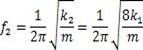
其中,m为设备质量。
支承上移后,频率的变化:

对比可得知,单层支撑机构下的设备的振动频率提高,且支承位于质心处,大幅减小地震下的偏心弯矩,有效的降低地震下的响应。由于从现有技术中的双层支撑机构简化为单层支撑机构,取消了间隙支承,在地震下无碰撞现象发生,有利于稳压器本体及顶部的管道、阀门抗震设计。通过本发明提供的单层支承结构,与当前核电站内普遍使用的两层支承结构不同,取消了常见的底部与顶部支承,可简化支撑楼板的土建设计,单层楼板即可满足固定需求,且单层楼板载荷比现有技术降低60%,有利于稳压器1以及支撑楼板的设计;支承结构设于稳压器1质心处,从而可使稳压器1顶部热胀位移降低50%,有利于稳压器1顶部辅助管道的布置,降低热胀应力;支座20与稳压器1之间的间隙设置,可有效释放稳压器1的热胀应力;本发明提供的支承结构还能够大幅减小地震下的偏心弯矩,有效的降低地震下的响应,有利于稳压器1本体以及相关管道、阀门的设计。
以上实施例仅表达了本发明的几种实施方式,其描述较为具体和详细, 但并不能因此而理解为对发明专利范围的限制。应当指出的是,对于本领域的普通技术人员来说,在不脱离本发明构思的前提下,还可以做出若干变形和改进,这些都属于本发明的保护范围。因此,本发明专利的保护范围应以所附权利要求为准。
Claims (12)
- 核电站稳压器的支承结构,其特征在于,所述支承结构设于稳压器(1)中部,包括与所述稳压器(1)固定连接的凸耳(10)以及与将所述稳压器(1)与支撑楼板固定连接的支座(20),所述支座(20)和所述凸耳(10)之间可拆卸连接;所述支座(20)与所述稳压器(1)间隙设置。
- 根据权利要求1所述的核电站稳压器的支承结构,其特征在于,所述凸耳(10)包括若干长度方向平行设置的第一肋板(11)以及连接数个所述第一肋板(11)的第二肋板(12),所述第一肋板(11)和所述第二肋板(12)均与所述稳压器(1)固定连接。
- 根据权利要求2所述的核电站稳压器的支承结构,其特征在于,所述第一肋板(11)的长度方向与所述稳压器(1)的长度方向平行设置,所述第一肋板(11)和所述第二肋板(12)均垂直于所述稳压器(1)表面固定设置。
- 根据权利要求3所述的核电站稳压器的支承结构,其特征在于,所述支座(20)与所述第二肋板(12)配合连接以将所述稳压器(1)固定在所述支撑楼板上。
- 根据权利要求4所述的核电站稳压器的支承结构,其特征在于,所述第二肋板(12)垂直设于若干所述第一肋板(11)下方,通过所述第二肋板(12)将若干所述第一肋板(11)连接为一体。
- 根据权利要求5所述的核电站稳压器的支承结构,其特征在于,所述支座(20)包括设于所述凸耳(10)下方的底座(21),以及用于盖设在所述凸耳(10)上的盖板(22),所述凸耳(10)夹设在所述底座(21)和所述盖板(22)之间从而与所述支座(20)连接设置。
- 根据权利要求6所述的核电站稳压器的支承结构,其特征在于,通过将所述第二肋板(12)夹设在所述底座(21)和盖板(22)之间,使所述凸耳(10)与所述支座(20)连接设置。
- 根据权利要求7所述的核电站稳压器的支承结构,其特征在于,所述第二肋板(12)包括用于夹设在所述底座(21)和所述盖板(22)之间的固定沿(121),所述固定沿(121)对称设于所述第二肋板(12)两侧,若干所述第一肋板(11)设于两所述固定沿(121)之间。
- 根据权利要求8所述的核电站稳压器的支承结构,其特征在于,所述底座(21)上还设有用于容纳所述第二肋板(12)的下陷(211),所述第二肋板(12)放置在所述下陷(211)中,所述盖板(22)盖设在所述固定沿(121)上以使所述凸耳(10)夹设固定在所述支座(20)上。
- 根据权利要求9所述的核电站稳压器的支承结构,其特征在于,所述下陷(211)的深度大于或等于所述第二肋板(12)的厚度。
- 根据权利要求6所述的核电站稳压器的支承结构,其特征在于,所述盖板(22)上和所述底座(21)之间通过螺栓实现可拆卸连接,所述盖板(22)和所述底座(21)上对应设有用于容纳所述螺栓的螺栓孔;所述螺栓将所述支座(20)固定在所述支撑楼板上。
- 根据权利要求1所述的核电站稳压器的支承结构,其特征在于,若干所述支承结构沿周环设于所述稳压器(1)的质心处。
Applications Claiming Priority (2)
| Application Number | Priority Date | Filing Date | Title |
|---|---|---|---|
| CN202110171293.XA CN113035381A (zh) | 2021-02-03 | 2021-02-03 | 核电站稳压器的支承结构 |
| CN202110171293.X | 2021-02-03 |
Publications (1)
| Publication Number | Publication Date |
|---|---|
| WO2022166233A1 true WO2022166233A1 (zh) | 2022-08-11 |
Family
ID=76460647
Family Applications (1)
| Application Number | Title | Priority Date | Filing Date |
|---|---|---|---|
| PCT/CN2021/121924 Ceased WO2022166233A1 (zh) | 2021-02-03 | 2021-09-29 | 核电站稳压器的支承结构 |
Country Status (2)
| Country | Link |
|---|---|
| CN (1) | CN113035381A (zh) |
| WO (1) | WO2022166233A1 (zh) |
Families Citing this family (1)
| Publication number | Priority date | Publication date | Assignee | Title |
|---|---|---|---|---|
| CN113035381A (zh) * | 2021-02-03 | 2021-06-25 | 中广核工程有限公司 | 核电站稳压器的支承结构 |
Citations (7)
| Publication number | Priority date | Publication date | Assignee | Title |
|---|---|---|---|---|
| CN202650562U (zh) * | 2012-06-08 | 2013-01-02 | 中国核动力研究设计院 | 一种反应堆压力容器模块式支座支承 |
| KR20130077599A (ko) * | 2011-12-29 | 2013-07-09 | 두산중공업 주식회사 | 분리형 가압기 운송구조물 |
| CN103474105A (zh) * | 2012-06-08 | 2013-12-25 | 中国核动力研究设计院 | 一种反应堆压力容器模块式支座支承 |
| US20200005950A1 (en) * | 2018-07-02 | 2020-01-02 | Invap S.E. | Compact reactor with horizontal steam generators and pressurizer |
| CN110853784A (zh) * | 2019-11-19 | 2020-02-28 | 中国核动力研究设计院 | 一种压水堆核电厂稳压器支承结构 |
| CN110853768A (zh) * | 2018-08-21 | 2020-02-28 | 中广核工程有限公司 | 核电站稳压器 |
| CN113035381A (zh) * | 2021-02-03 | 2021-06-25 | 中广核工程有限公司 | 核电站稳压器的支承结构 |
Family Cites Families (10)
| Publication number | Priority date | Publication date | Assignee | Title |
|---|---|---|---|---|
| US5152253A (en) * | 1991-01-28 | 1992-10-06 | Westinghouse Electric Corp. | Vessel structural support system |
| CN1312701C (zh) * | 2005-01-07 | 2007-04-25 | 清华大学 | 模块式高温气冷堆压力壳的无阻尼器支承系统 |
| CN103871497A (zh) * | 2012-12-13 | 2014-06-18 | 中国核动力研究设计院 | 反应堆压力容器悬臂式支承装置 |
| CN106384608B (zh) * | 2016-10-11 | 2018-05-08 | 中国核动力研究设计院 | 一种反应堆压力容器用抱箍拉梁型支承装置 |
| CN206437455U (zh) * | 2016-10-27 | 2017-08-25 | 青岛科技大学 | 一种新型立式容器支撑结构 |
| CN206861492U (zh) * | 2017-06-23 | 2018-01-09 | 中国核动力研究设计院 | 一种带有水平支承连接板的压水堆用蒸汽发生器 |
| CN108364699B (zh) * | 2018-04-13 | 2024-05-17 | 中广核研究院有限公司 | 一种用于金属冷却剂快堆的反应堆压力容器 |
| CN108962406B (zh) * | 2018-08-01 | 2024-05-10 | 中广核研究院有限公司 | 用于反应堆容器的单向滑动支承装置 |
| CN109215814B (zh) * | 2018-08-01 | 2024-03-22 | 中广核研究院有限公司 | 用于多容器系统的水平支承结构 |
| CN109243629B (zh) * | 2018-08-01 | 2024-03-22 | 中广核研究院有限公司 | 用于反应堆容器及柔性长管的模块化分层组合支承装置 |
-
2021
- 2021-02-03 CN CN202110171293.XA patent/CN113035381A/zh active Pending
- 2021-09-29 WO PCT/CN2021/121924 patent/WO2022166233A1/zh not_active Ceased
Patent Citations (7)
| Publication number | Priority date | Publication date | Assignee | Title |
|---|---|---|---|---|
| KR20130077599A (ko) * | 2011-12-29 | 2013-07-09 | 두산중공업 주식회사 | 분리형 가압기 운송구조물 |
| CN202650562U (zh) * | 2012-06-08 | 2013-01-02 | 中国核动力研究设计院 | 一种反应堆压力容器模块式支座支承 |
| CN103474105A (zh) * | 2012-06-08 | 2013-12-25 | 中国核动力研究设计院 | 一种反应堆压力容器模块式支座支承 |
| US20200005950A1 (en) * | 2018-07-02 | 2020-01-02 | Invap S.E. | Compact reactor with horizontal steam generators and pressurizer |
| CN110853768A (zh) * | 2018-08-21 | 2020-02-28 | 中广核工程有限公司 | 核电站稳压器 |
| CN110853784A (zh) * | 2019-11-19 | 2020-02-28 | 中国核动力研究设计院 | 一种压水堆核电厂稳压器支承结构 |
| CN113035381A (zh) * | 2021-02-03 | 2021-06-25 | 中广核工程有限公司 | 核电站稳压器的支承结构 |
Also Published As
| Publication number | Publication date |
|---|---|
| CN113035381A (zh) | 2021-06-25 |
Similar Documents
| Publication | Publication Date | Title |
|---|---|---|
| USRE47965E1 (en) | Seismic attenuation system for a nuclear reactor | |
| WO2022166233A1 (zh) | 核电站稳压器的支承结构 | |
| CN202650562U (zh) | 一种反应堆压力容器模块式支座支承 | |
| CN113944826A (zh) | 反应堆容器的保温组件 | |
| CN101832448B (zh) | 保温层结构 | |
| US20160076396A1 (en) | Turbine Exhaust Cylinder / Turbine Exhaust Manifold Bolted Stiffening Ribs | |
| CN213420287U (zh) | 加强减震型波纹管膨胀节 | |
| US4035974A (en) | Pressure tank for nuclear reactors with concrete enclosure | |
| CN108953854B (zh) | 反应堆支承装置 | |
| CN210716527U (zh) | 简易薄板减振联合支架 | |
| WO2018211771A1 (ja) | タンク型原子炉構造 | |
| KR102078907B1 (ko) | 중수로용 핵연료봉과 이를 포함하는 핵연료봉집합체 | |
| CN204242595U (zh) | 压水堆内置蒸汽稳压器隔热板及其构成的一体化压水堆 | |
| JPS60179589A (ja) | 直径に対して肉厚が小さいパイプの支持装置 | |
| CN223388563U (zh) | 一种锅炉止震结构 | |
| CN115060106B (zh) | 一种高温高压介质排放装置 | |
| CN219692643U (zh) | 悬浮式热隔离装置 | |
| CN121408847B (zh) | 一种外辐射加热的蓄热承压一体化电加热装置 | |
| CN216112748U (zh) | 一种供暖管道用补偿器 | |
| CN221743448U (zh) | 一种全方位大位移补偿u型隔震金属软管 | |
| CN121299693B (zh) | 一种海洋测量的防水gps定位结构及其使用方法 | |
| CN107293337A (zh) | 一种用于铅铋快堆双层反应堆容器的弹性支撑结构 | |
| CN112027392A (zh) | 容器支座系统 | |
| US20240304345A1 (en) | Nuclear modular isolated reactor support system assembly and modules | |
| CN212004728U (zh) | 一种耐高温的高压套管补偿器 |
Legal Events
| Date | Code | Title | Description |
|---|---|---|---|
| 121 | Ep: the epo has been informed by wipo that ep was designated in this application |
Ref document number: 21924230 Country of ref document: EP Kind code of ref document: A1 |
|
| NENP | Non-entry into the national phase |
Ref country code: DE |
|
| 122 | Ep: pct application non-entry in european phase |
Ref document number: 21924230 Country of ref document: EP Kind code of ref document: A1 |