WO2022163488A1 - 射出装置 - Google Patents
射出装置 Download PDFInfo
- Publication number
- WO2022163488A1 WO2022163488A1 PCT/JP2022/001948 JP2022001948W WO2022163488A1 WO 2022163488 A1 WO2022163488 A1 WO 2022163488A1 JP 2022001948 W JP2022001948 W JP 2022001948W WO 2022163488 A1 WO2022163488 A1 WO 2022163488A1
- Authority
- WO
- WIPO (PCT)
- Prior art keywords
- screw
- bush
- outer peripheral
- inner peripheral
- protrusion
- Prior art date
- Legal status (The legal status is an assumption and is not a legal conclusion. Google has not performed a legal analysis and makes no representation as to the accuracy of the status listed.)
- Ceased
Links
Images


Classifications
-
- B—PERFORMING OPERATIONS; TRANSPORTING
- B29—WORKING OF PLASTICS; WORKING OF SUBSTANCES IN A PLASTIC STATE IN GENERAL
- B29C—SHAPING OR JOINING OF PLASTICS; SHAPING OF MATERIAL IN A PLASTIC STATE, NOT OTHERWISE PROVIDED FOR; AFTER-TREATMENT OF THE SHAPED PRODUCTS, e.g. REPAIRING
- B29C45/00—Injection moulding, i.e. forcing the required volume of moulding material through a nozzle into a closed mould; Apparatus therefor
- B29C45/17—Component parts, details or accessories; Auxiliary operations
- B29C45/1775—Connecting parts, e.g. injection screws, ejectors, to drive means
-
- B—PERFORMING OPERATIONS; TRANSPORTING
- B29—WORKING OF PLASTICS; WORKING OF SUBSTANCES IN A PLASTIC STATE IN GENERAL
- B29C—SHAPING OR JOINING OF PLASTICS; SHAPING OF MATERIAL IN A PLASTIC STATE, NOT OTHERWISE PROVIDED FOR; AFTER-TREATMENT OF THE SHAPED PRODUCTS, e.g. REPAIRING
- B29C45/00—Injection moulding, i.e. forcing the required volume of moulding material through a nozzle into a closed mould; Apparatus therefor
- B29C45/17—Component parts, details or accessories; Auxiliary operations
- B29C45/46—Means for plasticising or homogenising the moulding material or forcing it into the mould
- B29C45/47—Means for plasticising or homogenising the moulding material or forcing it into the mould using screws
- B29C45/50—Axially movable screw
- B29C45/5008—Drive means therefor
-
- B—PERFORMING OPERATIONS; TRANSPORTING
- B29—WORKING OF PLASTICS; WORKING OF SUBSTANCES IN A PLASTIC STATE IN GENERAL
- B29C—SHAPING OR JOINING OF PLASTICS; SHAPING OF MATERIAL IN A PLASTIC STATE, NOT OTHERWISE PROVIDED FOR; AFTER-TREATMENT OF THE SHAPED PRODUCTS, e.g. REPAIRING
- B29C45/00—Injection moulding, i.e. forcing the required volume of moulding material through a nozzle into a closed mould; Apparatus therefor
- B29C45/17—Component parts, details or accessories; Auxiliary operations
- B29C45/46—Means for plasticising or homogenising the moulding material or forcing it into the mould
- B29C45/58—Details
- B29C45/60—Screws
-
- B—PERFORMING OPERATIONS; TRANSPORTING
- B29—WORKING OF PLASTICS; WORKING OF SUBSTANCES IN A PLASTIC STATE IN GENERAL
- B29C—SHAPING OR JOINING OF PLASTICS; SHAPING OF MATERIAL IN A PLASTIC STATE, NOT OTHERWISE PROVIDED FOR; AFTER-TREATMENT OF THE SHAPED PRODUCTS, e.g. REPAIRING
- B29C45/00—Injection moulding, i.e. forcing the required volume of moulding material through a nozzle into a closed mould; Apparatus therefor
- B29C45/17—Component parts, details or accessories; Auxiliary operations
- B29C45/46—Means for plasticising or homogenising the moulding material or forcing it into the mould
- B29C45/58—Details
- B29C45/62—Barrels or cylinders
-
- B—PERFORMING OPERATIONS; TRANSPORTING
- B29—WORKING OF PLASTICS; WORKING OF SUBSTANCES IN A PLASTIC STATE IN GENERAL
- B29C—SHAPING OR JOINING OF PLASTICS; SHAPING OF MATERIAL IN A PLASTIC STATE, NOT OTHERWISE PROVIDED FOR; AFTER-TREATMENT OF THE SHAPED PRODUCTS, e.g. REPAIRING
- B29C45/00—Injection moulding, i.e. forcing the required volume of moulding material through a nozzle into a closed mould; Apparatus therefor
- B29C45/17—Component parts, details or accessories; Auxiliary operations
- B29C45/46—Means for plasticising or homogenising the moulding material or forcing it into the mould
- B29C45/47—Means for plasticising or homogenising the moulding material or forcing it into the mould using screws
- B29C45/50—Axially movable screw
- B29C45/5008—Drive means therefor
- B29C2045/504—Drive means therefor electric motors for rotary and axial movement of the screw being coaxial with the screw
-
- B—PERFORMING OPERATIONS; TRANSPORTING
- B29—WORKING OF PLASTICS; WORKING OF SUBSTANCES IN A PLASTIC STATE IN GENERAL
- B29C—SHAPING OR JOINING OF PLASTICS; SHAPING OF MATERIAL IN A PLASTIC STATE, NOT OTHERWISE PROVIDED FOR; AFTER-TREATMENT OF THE SHAPED PRODUCTS, e.g. REPAIRING
- B29C45/00—Injection moulding, i.e. forcing the required volume of moulding material through a nozzle into a closed mould; Apparatus therefor
- B29C45/17—Component parts, details or accessories; Auxiliary operations
- B29C45/46—Means for plasticising or homogenising the moulding material or forcing it into the mould
- B29C45/47—Means for plasticising or homogenising the moulding material or forcing it into the mould using screws
- B29C45/50—Axially movable screw
- B29C45/5008—Drive means therefor
- B29C2045/5048—Drive means therefor screws axially driven and rotated by a drive shaft having a screw threaded part and spline part
-
- B—PERFORMING OPERATIONS; TRANSPORTING
- B29—WORKING OF PLASTICS; WORKING OF SUBSTANCES IN A PLASTIC STATE IN GENERAL
- B29C—SHAPING OR JOINING OF PLASTICS; SHAPING OF MATERIAL IN A PLASTIC STATE, NOT OTHERWISE PROVIDED FOR; AFTER-TREATMENT OF THE SHAPED PRODUCTS, e.g. REPAIRING
- B29C45/00—Injection moulding, i.e. forcing the required volume of moulding material through a nozzle into a closed mould; Apparatus therefor
- B29C45/17—Component parts, details or accessories; Auxiliary operations
- B29C45/46—Means for plasticising or homogenising the moulding material or forcing it into the mould
- B29C45/47—Means for plasticising or homogenising the moulding material or forcing it into the mould using screws
- B29C45/50—Axially movable screw
- B29C45/5008—Drive means therefor
- B29C2045/5064—Drive means therefor coupling means between rotation motor and rectilinear drive motor
-
- B—PERFORMING OPERATIONS; TRANSPORTING
- B29—WORKING OF PLASTICS; WORKING OF SUBSTANCES IN A PLASTIC STATE IN GENERAL
- B29C—SHAPING OR JOINING OF PLASTICS; SHAPING OF MATERIAL IN A PLASTIC STATE, NOT OTHERWISE PROVIDED FOR; AFTER-TREATMENT OF THE SHAPED PRODUCTS, e.g. REPAIRING
- B29C2945/00—Indexing scheme relating to injection moulding, i.e. forcing the required volume of moulding material through a nozzle into a closed mould
- B29C2945/76—Measuring, controlling or regulating
- B29C2945/76003—Measured parameter
- B29C2945/7602—Torque
-
- B—PERFORMING OPERATIONS; TRANSPORTING
- B29—WORKING OF PLASTICS; WORKING OF SUBSTANCES IN A PLASTIC STATE IN GENERAL
- B29C—SHAPING OR JOINING OF PLASTICS; SHAPING OF MATERIAL IN A PLASTIC STATE, NOT OTHERWISE PROVIDED FOR; AFTER-TREATMENT OF THE SHAPED PRODUCTS, e.g. REPAIRING
- B29C2945/00—Indexing scheme relating to injection moulding, i.e. forcing the required volume of moulding material through a nozzle into a closed mould
- B29C2945/76—Measuring, controlling or regulating
- B29C2945/76003—Measured parameter
- B29C2945/76083—Position
- B29C2945/76093—Angular position
-
- B—PERFORMING OPERATIONS; TRANSPORTING
- B29—WORKING OF PLASTICS; WORKING OF SUBSTANCES IN A PLASTIC STATE IN GENERAL
- B29C—SHAPING OR JOINING OF PLASTICS; SHAPING OF MATERIAL IN A PLASTIC STATE, NOT OTHERWISE PROVIDED FOR; AFTER-TREATMENT OF THE SHAPED PRODUCTS, e.g. REPAIRING
- B29C2945/00—Indexing scheme relating to injection moulding, i.e. forcing the required volume of moulding material through a nozzle into a closed mould
- B29C2945/76—Measuring, controlling or regulating
- B29C2945/76177—Location of measurement
- B29C2945/7618—Injection unit
- B29C2945/76214—Injection unit drive means
-
- B—PERFORMING OPERATIONS; TRANSPORTING
- B29—WORKING OF PLASTICS; WORKING OF SUBSTANCES IN A PLASTIC STATE IN GENERAL
- B29C—SHAPING OR JOINING OF PLASTICS; SHAPING OF MATERIAL IN A PLASTIC STATE, NOT OTHERWISE PROVIDED FOR; AFTER-TREATMENT OF THE SHAPED PRODUCTS, e.g. REPAIRING
- B29C2945/00—Indexing scheme relating to injection moulding, i.e. forcing the required volume of moulding material through a nozzle into a closed mould
- B29C2945/76—Measuring, controlling or regulating
- B29C2945/76344—Phase or stage of measurement
- B29C2945/76381—Injection
-
- B—PERFORMING OPERATIONS; TRANSPORTING
- B29—WORKING OF PLASTICS; WORKING OF SUBSTANCES IN A PLASTIC STATE IN GENERAL
- B29C—SHAPING OR JOINING OF PLASTICS; SHAPING OF MATERIAL IN A PLASTIC STATE, NOT OTHERWISE PROVIDED FOR; AFTER-TREATMENT OF THE SHAPED PRODUCTS, e.g. REPAIRING
- B29C2945/00—Indexing scheme relating to injection moulding, i.e. forcing the required volume of moulding material through a nozzle into a closed mould
- B29C2945/76—Measuring, controlling or regulating
- B29C2945/76494—Controlled parameter
- B29C2945/76568—Position
- B29C2945/76581—Position distance
-
- B—PERFORMING OPERATIONS; TRANSPORTING
- B29—WORKING OF PLASTICS; WORKING OF SUBSTANCES IN A PLASTIC STATE IN GENERAL
- B29C—SHAPING OR JOINING OF PLASTICS; SHAPING OF MATERIAL IN A PLASTIC STATE, NOT OTHERWISE PROVIDED FOR; AFTER-TREATMENT OF THE SHAPED PRODUCTS, e.g. REPAIRING
- B29C2945/00—Indexing scheme relating to injection moulding, i.e. forcing the required volume of moulding material through a nozzle into a closed mould
- B29C2945/76—Measuring, controlling or regulating
- B29C2945/76655—Location of control
- B29C2945/76658—Injection unit
- B29C2945/76692—Injection unit drive means
-
- B—PERFORMING OPERATIONS; TRANSPORTING
- B29—WORKING OF PLASTICS; WORKING OF SUBSTANCES IN A PLASTIC STATE IN GENERAL
- B29C—SHAPING OR JOINING OF PLASTICS; SHAPING OF MATERIAL IN A PLASTIC STATE, NOT OTHERWISE PROVIDED FOR; AFTER-TREATMENT OF THE SHAPED PRODUCTS, e.g. REPAIRING
- B29C2945/00—Indexing scheme relating to injection moulding, i.e. forcing the required volume of moulding material through a nozzle into a closed mould
- B29C2945/76—Measuring, controlling or regulating
- B29C2945/76822—Phase or stage of control
- B29C2945/76859—Injection
-
- B—PERFORMING OPERATIONS; TRANSPORTING
- B29—WORKING OF PLASTICS; WORKING OF SUBSTANCES IN A PLASTIC STATE IN GENERAL
- B29C—SHAPING OR JOINING OF PLASTICS; SHAPING OF MATERIAL IN A PLASTIC STATE, NOT OTHERWISE PROVIDED FOR; AFTER-TREATMENT OF THE SHAPED PRODUCTS, e.g. REPAIRING
- B29C45/00—Injection moulding, i.e. forcing the required volume of moulding material through a nozzle into a closed mould; Apparatus therefor
- B29C45/17—Component parts, details or accessories; Auxiliary operations
- B29C45/76—Measuring, controlling or regulating
Definitions
- the present invention relates to an injection device.
- Japanese Patent Application Laid-Open No. 2019-055488 discloses a motor control unit that controls a linear motion motor and a rotary motion motor.
- the linear motion motor is a motor that moves the bush in the axial direction of the screw.
- the rotational motion motor is a motor that rotates the bush around the axis of the screw.
- the motor control unit controls the linear motion motor to advance the bushing in the direction of approaching the screw from the state separated from the screw.
- the motor control section controls the motor for rotary motion to rotate the bush.
- the present invention provides an injection device that can improve the working efficiency of spline fitting.
- An injection device comprising: a screw arranged along a front-rear direction for injecting an injection resin and a rearward direction opposite to the forward direction; and a bush formed so as to be spline-engageable with the screw.
- the screw has a plurality of outer peripheral protrusions formed on the outer peripheral surface of the rear end side of the screw and extending along the front-rear direction at intervals in the peripheral direction of the screw,
- Each of the plurality of outer peripheral protrusions has an outer peripheral protrusion slope inclined so that the outer peripheral protrusion width along the circumferential direction of the screw becomes smaller toward the rear end of the outer peripheral protrusion, and an outer peripheral protrusion slope toward the rear end of the outer peripheral protrusion.
- the bushing has a through hole extending in the front-rear direction, and a plurality of inner peripheral protrusions formed on the inner peripheral surface of the through hole and extending in the front-rear direction at intervals in the peripheral direction of the through hole.
- Each of the plurality of inner peripheral protrusions includes an inner peripheral protrusion slope inclined so that the width of the inner peripheral protrusion along the circumferential direction of the through hole becomes smaller toward the front end of the inner peripheral protrusion, and the inner peripheral protrusion.
- a second inner peripheral projection slope inclined so that the inner diameter of the bush increases toward the front end of the A rear end of each of the plurality of outer peripheral protrusions and a front end of each of the plurality of inner peripheral protrusions do not have a flat surface.
- spline fitting can be achieved by advancing the bushing with respect to the screw without rotating the bushing. As a result, the work efficiency of spline fitting can be improved.
- FIG. 1 is a schematic diagram showing an injection device according to one embodiment.
- FIG. 2 shows a screw and bushing.
- 3A is a cross-sectional view of the screw of FIG. 2
- FIG. 3B is a cross-sectional view of the bushing of FIG.
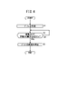
- FIG. 4 is a flow chart showing a procedure of control processing executed by the motor control section to spline-fit the screw and the bush.
- FIG. 5 is a diagram showing a screw and bush of Modification 1.
- FIG. 1 is a schematic diagram showing an injection device 10 according to one embodiment.
- the injection device 10 injects molding resin into a mold.
- the injection direction for injecting the molding resin is the forward direction
- the direction opposite to the injection direction is the rearward direction.
- the injection device 10 is provided with a screw 12 , a bush 14 , a bush fastening portion 16 and a drive mechanism 18 .
- the screw 12 is accommodated in the through hole 20H of the cylinder 20.
- the screw 12 rotates to forward the molding resin introduced into the through-hole 20H.
- a nozzle 22 is provided at the front end of the cylinder 20 , and the molding resin fed by the screw 12 is injected from the nozzle 22 .
- the screw 12 has a screw portion 12A and a spline portion 12B.
- the screw part 12A is the front part of the screw 12.
- a spiral protrusion 12P is formed on the outer peripheral surface of the screw portion 12A.
- the spline portion 12B is the rear portion of the screw 12 and is connected to the rear end of the screw portion 12A.
- An outer peripheral surface of the spline portion 12B is formed with protrusions and recesses that can be spline-fitted with the bush 14 .
- the bushing 14 is spline-fitted with the screw 12 .
- the bushing 14 has a through hole 14H penetrating in the front-rear direction.
- the inner peripheral surface of the through hole 14H is formed with irregularities so that it can be spline-fitted with the spline portion 12B.
- the bush 14 is provided with an annular projection 14A projecting rearward from the rear end surface of the bush 14 .
- the bush fastening portion 16 fixes the bush 14 behind the bush 14 .
- the bush fastening portion 16 has a concave portion 16A in which the convex portion 14A of the bush 14 is accommodated.
- the bushing 14, in which the convex portion 14A is accommodated in the concave portion 16A, is fixed to the bush fastening portion 16 with a bolt.
- the drive mechanism 18 is a mechanism that drives at least one of the screw 12 and the bush 14 so as to move the bush 14 relative to the screw 12 .
- the drive mechanism 18 that drives the bush 14 is used.
- the drive mechanism 18 includes a linear motor 24 , a rotary motor 26 and a motor control section 28 .
- the direct-acting motor 24 is a motor that advances and retracts the bush 14 in the front-rear direction.
- a motor shaft of the direct-acting motor 24 is connected to a ball screw 30 that rotates together with the motor shaft.
- a sliding portion 32 is attached to the ball screw 30 so as to move the ball screw 30 back and forth in accordance with the rotation of the direct-acting motor 24 .
- a linear motion gear 34 is rotatably attached to the sliding portion 32 .
- the linear motion gear 34 is fixed to the rear end of the bush fastening portion 16 .
- the linear motor 24 is provided with an encoder 36 that detects the rotation angle of the linear motor 24 and a detector 38 that detects the linear torque of the linear motor 24 .
- the rotary motor 26 is a motor that rotates the bush 14 .
- a rotation gear 40 that meshes with the linear motion gear 34 is connected to the motor shaft of the rotation motor 26 .
- the rotary motor 26 is provided with an encoder 42 that detects the rotation angle of the rotary motor 26 .
- the direct-acting gear 34 moves back and forth via the ball screw 30 and the sliding portion 32 in accordance with the rotation of the direct-acting motor 24 .
- the rotation gear 40 and the rotary motor 26 meshing with the linear motion gear 34 move in the longitudinal direction, and the bush 14 moves in the longitudinal direction via the bush fastening portion 16 to which the linear motion gear 34 is fixed.
- the rotation gear 40 rotates according to the rotation of the rotary motor 26 .
- the linear motion gear 34 meshing with the rotation gear 40 rotates, and the bush 14 rotates via the bush fastening portion 16 to which the linear motion gear 34 is fixed.
- the motor control unit 28 advances and retreats the bush 14 by controlling the direct-acting motor 24 so that the rotation angle detected by the encoder 36 becomes a target value. Further, the motor control unit 28 rotates the bush 14 by controlling the rotary motor 26 so that the rotation angle detected by the encoder 42 becomes a target value.
- the motor control unit 28 performs control processing for controlling only the linear motion motor 24 while monitoring the linear motion torque detected by the detection unit 38, so that the screw 12 and the bush 14 are spline-fitted.
- FIG. 2 shows the screw 12 and the bush 14
- FIG. 3A shows a cross section of the screw 12 in FIG. 2
- FIG. 3B shows a cross section of the bush 14 in FIG.
- a plurality of outer peripheral protrusions 50 are formed on the outer peripheral surface of the spline portion 12B and extend in the front-rear direction at intervals in the peripheral direction of the spline portion 12B.
- Each of the plurality of outer peripheral protrusions 50 is divided by a fitting groove 52 that makes a round along the circumferential direction of the spline portion 12B.
- An annular retainer 46 ( FIG. 1 ) is fitted in the fitting groove 52 .
- each of the plurality of outer peripheral projections 50 is the same. Only one of the plurality of outer peripheral protrusions 50 will be described below regarding the shape of the outer peripheral protrusion 50 .
- a rear end of the outer peripheral protrusion 50 is formed in a sharp shape or a rounded shape. That is, the rear end of the outer peripheral projection 50 of the screw 12 does not have a flat surface.
- an outer peripheral protrusion slope 50S and a second outer peripheral protrusion slope 50SS are formed toward the rear end of the outer peripheral protrusion 50. As shown in FIG.
- the outer peripheral protrusion slope 50S is formed on one of both side surfaces 50F1 and 50F2 of the outer peripheral protrusion 50 in the circumferential direction of the screw 12.
- the outer peripheral protrusion slope 50S is inclined so that the outer peripheral protrusion width 50W along the circumferential direction of the screw 12 becomes smaller toward the rear end.
- the second outer peripheral protrusion slope 50SS is inclined so that the outer diameter of the screw 12 decreases toward the rear end of the outer peripheral protrusion 50 . That is, the second outer peripheral protrusion slope 50SS is inclined so that the radius R1 (FIG. 3A) of the screw 12 from the rotation center line LN1 of the screw 12 becomes smaller toward the rear end of the outer peripheral protrusion 50.
- a plurality of inner peripheral protrusions 60 are formed on the inner peripheral surface of the through hole 14H of the bush 14 and extend in the front-rear direction at intervals in the peripheral direction of the through hole 14H.
- Each of the plurality of inner peripheral projections 60 has the same shape. Only one of the plurality of inner peripheral protrusions 60 will be described below regarding the shape of the inner peripheral protrusion 60 .
- a front end of the inner peripheral protrusion 60 is formed in a sharp shape or a rounded shape. That is, the front end of the inner peripheral projection 60 of the bushing 14 does not have a flat surface. In addition, there is no plane orthogonal to the center line LN2 (FIG. 2) of the through hole 14H of the bush 14 at the foremost front end of the bush 14 .
- an inner peripheral protrusion slope 60S and a second inner peripheral protrusion slope 60SS are formed toward the front end of the inner peripheral protrusion 60. As shown in FIG.
- the inner peripheral protrusion slope 60S is formed on one of both side surfaces 60F1 and 60F2 of the inner peripheral protrusion 60 in the circumferential direction of the through hole 14H.
- the inner peripheral protrusion slope 60S is inclined so that the inner peripheral protrusion width 60W along the circumferential direction of the through hole 14H becomes smaller toward the front end.
- the second inner peripheral projection slope 60SS is inclined so that the diameter of the through hole 14H of the bush 14 expands toward the front end of the inner peripheral projection 60 . That is, the second inner peripheral protrusion slope 60SS is inclined so that the radius R2 (FIG. 3B) of the through hole 14H from the center line LN2 of the through hole 14H increases toward the front end of the inner peripheral protrusion 60.
- Cs1 in the formula (1) is the height 50H (FIG. 3A) of the second outer peripheral projection slope 50SS.
- Cb1 in the formula (1) is the height 60H (FIG. 3B) of the second inner peripheral projection slope 60SS.
- Ls1 in the formula (1) is the gap GP1 ( FIG. 1 ) between the outer peripheral projection 50 and the cylinder 20 when the screw 12 fitted to the bush 14 is accommodated in the cylinder 20 .
- Lb1 in the expression (1) is a gap GP2 between the outer periphery of the protrusion 14A of the bush 14 and the inner periphery of the recess 16A of the bush fastening portion 16 when the bush 14 is fixed to the bush fastening portion 16 (FIG. 1). is.
- the height 50H (FIG. 3A) of the second outer peripheral protrusion slope 50SS is the radial length of the screw 12 between the most protruding position of the outer peripheral protrusion slope 50S and the rear end of the outer peripheral protrusion slope 50S ( projection distance).
- the height 60H (FIG. 3B) of the second inner peripheral protrusion slope 60SS is the radial length of the bush 14 between the most projecting position of the inner peripheral protrusion slope 60S and the front end of the inner peripheral protrusion slope 60S. (protrusion distance).
- FIG. 4 is a flowchart showing the procedure of control processing executed by the motor control unit 28 to spline-fit the screw 12 and the bush 14 together.
- This control process is started after the bush 14 is moved to a predetermined fitting start position spaced rearward from the rear end surface of the screw 12 .
- the rotation center line LN1 (FIG. 2) of the screw 12 and the center line LN2 (FIG. 2) of the through hole 14H of the bush 14 must not match if the formula (1) is satisfied. good too.
- step S ⁇ b>1 the motor control unit 28 advances the bushing 14 toward the screw 12 .
- the control process proceeds to step S2.
- step S2 the motor control unit 28 compares the linear motion torque detected by the detection unit 38 while the bush 14 is advancing with the linear motion torque threshold.
- the control process remains at step S2.
- the control process proceeds to step S3.
- the phenomenon in which the direct torque exceeds the direct torque threshold occurs when the rear end surface of the screw 12 spline-fitted with the bush 14 is in contact with the bottom surface of the recess 16A of the bush fastening portion 16.
- step S3 the motor control unit 28 stops advancing the bush 14 when the direct torque exceeds the direct torque threshold.
- the control process ends.
- the outer peripheral protrusion 50 of the screw 12 is formed with the outer peripheral protrusion slope 50S and the second outer peripheral protrusion slope 50SS, and the rear end of the outer peripheral protrusion 50 does not have a flat surface.
- the inner peripheral protrusion 60 of the bush 14 is formed with an inner peripheral protrusion slope 60S and a second inner peripheral protrusion slope 60SS, and the front end of the inner peripheral protrusion 60 does not have a flat surface.
- the relationship of the above formula (1) is established.
- the bushing 14 can be spline-fitted with the screw 12 by advancing the bushing 14 without rotating the bushing 14. can.
- the injection device 10 also includes a motor control section 28 that controls the direct-acting motor 24 .
- the motor control unit 28 advances the bushing 14 from a position separated from the screw 12, and stops the bushing 14 when the linear torque exceeds the linear torque threshold.
- FIG. 5 is a diagram showing the screw 12 and bushing 14 of Modification 1. As shown in FIG. In FIG. 5, the same reference numerals are assigned to the same configurations as those described in the embodiment. In addition, in this modification, the description which overlaps with embodiment is omitted.
- an outer peripheral protrusion slope 50S of the outer peripheral protrusion 50 is formed on each of the two circumferential side surfaces 50F1 and 50F2 of the screw 12.
- inner peripheral projection slopes 60S of the inner peripheral projection 60 are formed on both side surfaces 60F1 and 60F2 in the circumferential direction of the through hole 14H. Even if it is formed in this way, spline fitting can be achieved by forward movement of the bush 14 with respect to the screw 12 without rotating the bush 14, as in the embodiment.
- the second outer peripheral protrusion slope 50SS may be formed between the outer peripheral protrusions 50 in addition to the outer peripheral protrusions 50 as in the first modification.
- the rear end of the outer peripheral projection 50 may be positioned on the same plane as the rear end surface of the screw 12 or may be positioned forward of the rear end surface of the screw 12 . That is, the rear end of the outer peripheral projection 50 in the embodiment may be positioned forward of the rear end surface of the screw 12 . Further, the rear end of the outer peripheral projection 50 in Modification 1 may be positioned on the same plane as the rear end surface of the screw 12 .
- the front end of the inner peripheral projection 60 may be positioned on the same plane as the front end face of the bush 14 or may be positioned behind the front end face of the bush 14 .
- the front end of the inner peripheral projection 60 in the embodiment may be positioned rearward of the front end face of the bush 14 .
- the front end of the inner peripheral projection 60 in Modification 1 may be positioned on the same plane as the front end surface of the bush 14 .
- the present invention provides a screw (12) arranged along the front-rear direction of injecting a resin for injection and the rearward direction opposite to the front-rear direction, and a bush formed so as to be spline-fitted with the screw (12). (14), wherein the screw is formed on the outer peripheral surface of the rear end side of the screw and extends along the front-rear direction at intervals in the circumferential direction of the screw. , and each of the plurality of outer peripheral protrusions is inclined so that the outer peripheral protrusion width (50W) along the circumferential direction of the screw becomes smaller toward the rear end of the outer peripheral protrusion.
- An outer peripheral protrusion slope (50S) and a second outer peripheral protrusion slope (50SS) inclined so that the outer diameter of the screw decreases toward the rear end of the outer peripheral protrusion are formed. and a plurality of inner peripheral projections (60) formed on the inner peripheral surface of the through hole and extending along the front-rear direction at intervals in the peripheral direction of the through hole.
- each of the plurality of inner peripheral protrusions has an inner peripheral protrusion slope (60S ) and a second inner peripheral protrusion slope (60SS) inclined so that the inner diameter of the bush increases toward the front end of the inner peripheral protrusion, and the rear end and the rear end of each of the plurality of outer peripheral protrusions are formed.
- a front end of each of the plurality of inner peripheral projections does not have a flat surface. This allows forward motion of the bushing to the screw to provide a spline fit without rotating the bushing. As a result, the working efficiency of spline fitting can be improved.
- the outer peripheral protrusion slope is formed on one of both side surfaces (50F1, 50F2) in the circumferential direction of the screw on the rear end side of each of the plurality of outer peripheral protrusions
- the inner peripheral protrusion slope is formed on one of the plurality of inner peripheral protrusions.
- the outer peripheral protrusion slope is formed on each of both side surfaces in the circumferential direction of the screw on the rear end side of each of the plurality of outer peripheral protrusions
- the inner peripheral protrusion slope is formed on the front end side of each of the plurality of inner peripheral protrusions. may be formed on each of both side surfaces in the circumferential direction of the through hole in . This allows forward motion of the bushing to the screw to provide a spline fit without rotating the bushing.
- the bush is provided with a protrusion (14A) projecting from the rear end surface of the bush, and the injection device has a recess (16A) in which the protrusion is accommodated, and the protrusion is accommodated in the recess. and a cylinder (20) in which the screw is accommodated, wherein Cs1 is the height (50H) of the second outer peripheral projection slope, and the second Let Cb1 be the height (60H) of the slope of the inner peripheral protrusion, Ls1 be the gap (GP1) between the outer peripheral protrusion and the cylinder when the screw fitted to the bush is accommodated in the cylinder, If the gap (GP2) between the outer periphery of the protrusion and the inner periphery of the recess when the bush is fixed to the bush fastening portion is Lb1, the relationship Cs1+Cb1>Ls1+Lb1 is established. good too. This allows spline engagement of the bushing with respect to the screw by forward motion of the bushing without rotating the bushing
- the injection device includes a direct-acting motor (24) for advancing and retreating the bush in the longitudinal direction with respect to the screw, a detection section (38) for detecting the direct-acting torque of the direct-acting motor, and a motor control unit (28) that controls the direct-acting motor so as to advance the bushing from the separated position and stop the bushing when the direct-acting torque exceeds a direct-acting torque threshold value; good too.
- a direct-acting motor for advancing and retreating the bush in the longitudinal direction with respect to the screw
- a detection section (38) for detecting the direct-acting torque of the direct-acting motor
- a motor control unit (28) that controls the direct-acting motor so as to advance the bushing from the separated position and stop the bushing when the direct-acting torque exceeds a direct-acting torque threshold value; good too.
Landscapes
- Engineering & Computer Science (AREA)
- Manufacturing & Machinery (AREA)
- Mechanical Engineering (AREA)
- Injection Moulding Of Plastics Or The Like (AREA)
- Gears, Cams (AREA)
Priority Applications (4)
| Application Number | Priority Date | Filing Date | Title |
|---|---|---|---|
| DE112022000324.3T DE112022000324T5 (de) | 2021-01-29 | 2022-01-20 | Einspritzvorrichtung |
| US18/273,223 US20240149513A1 (en) | 2021-01-29 | 2022-01-20 | Injection device |
| CN202280011080.3A CN116745094A (zh) | 2021-01-29 | 2022-01-20 | 注射装置 |
| JP2022578301A JP7553611B2 (ja) | 2021-01-29 | 2022-01-20 | 射出装置 |
Applications Claiming Priority (2)
| Application Number | Priority Date | Filing Date | Title |
|---|---|---|---|
| JP2021013465 | 2021-01-29 | ||
| JP2021-013465 | 2021-01-29 |
Publications (1)
| Publication Number | Publication Date |
|---|---|
| WO2022163488A1 true WO2022163488A1 (ja) | 2022-08-04 |
Family
ID=82654487
Family Applications (1)
| Application Number | Title | Priority Date | Filing Date |
|---|---|---|---|
| PCT/JP2022/001948 Ceased WO2022163488A1 (ja) | 2021-01-29 | 2022-01-20 | 射出装置 |
Country Status (5)
| Country | Link |
|---|---|
| US (1) | US20240149513A1 (https=) |
| JP (1) | JP7553611B2 (https=) |
| CN (1) | CN116745094A (https=) |
| DE (1) | DE112022000324T5 (https=) |
| WO (1) | WO2022163488A1 (https=) |
Families Citing this family (2)
| Publication number | Priority date | Publication date | Assignee | Title |
|---|---|---|---|---|
| JP7082255B1 (ja) * | 2021-01-29 | 2022-06-07 | ファナック株式会社 | 射出装置および制御方法 |
| JP2024034856A (ja) * | 2022-09-01 | 2024-03-13 | 株式会社日本製鋼所 | 駆動機構、射出装置および射出成形機 |
Citations (2)
| Publication number | Priority date | Publication date | Assignee | Title |
|---|---|---|---|---|
| JP2018044642A (ja) * | 2016-09-15 | 2018-03-22 | 株式会社リコー | 駆動伝達装置および画像形成装置 |
| JP2019055488A (ja) * | 2017-09-20 | 2019-04-11 | ファナック株式会社 | 射出成形機および射出成形機の制御方法 |
Family Cites Families (30)
| Publication number | Priority date | Publication date | Assignee | Title |
|---|---|---|---|---|
| US2445184A (en) * | 1947-09-10 | 1948-07-13 | John J Parker | Mandrel |
| US2680031A (en) * | 1951-02-03 | 1954-06-01 | Lear Inc | Shaft sealing structure |
| US2881710A (en) * | 1955-08-22 | 1959-04-14 | Jabsco Pump Co | Shaft seal with replaceable sleeve |
| US3197216A (en) * | 1962-07-31 | 1965-07-27 | Homer E Jackson | Alignment control and seal for spline drives |
| US3508418A (en) * | 1968-07-30 | 1970-04-28 | Conover & Co Inc C E | Spline closure seal |
| GB1585177A (en) * | 1976-09-04 | 1981-02-25 | Gkn Transmissions Ltd | Splined joints |
| US4127275A (en) * | 1978-01-17 | 1978-11-28 | The United States Of America As Represented By The Secretary Of The Navy | Self-disengaging static seal |
| US4153260A (en) * | 1978-06-02 | 1979-05-08 | Dana Corporation | Slip spline seal assembly |
| US4215869A (en) * | 1979-04-16 | 1980-08-05 | Garlock Inc. | Splined shaft seal article and apparatus |
| US4580996A (en) * | 1983-07-15 | 1986-04-08 | Rockwell International Corporation | Driveline apparatus |
| JPS60132722A (ja) * | 1983-12-22 | 1985-07-15 | Fanuc Ltd | 射出成形機における射出機構 |
| JP2673266B2 (ja) * | 1988-11-28 | 1997-11-05 | 小橋工業株式会社 | 農作業機の動力伝達装置 |
| US5660591A (en) * | 1996-01-31 | 1997-08-26 | Reliance Electric Industrial Co. | Flexible coupling device |
| AT2062U1 (de) * | 1997-04-09 | 1998-04-27 | Engel Gmbh Maschbau | Einspritzaggregat für spritzgiessmaschinen |
| EP1083036B1 (en) * | 1999-09-07 | 2002-06-19 | Negri Bossi S.P.A. | Electric injection assembly for injection presses for plastic materials |
| JP2002258675A (ja) * | 2000-12-27 | 2002-09-11 | Matsushita Electric Ind Co Ltd | 画像形成装置 |
| JP2002207331A (ja) * | 2001-01-09 | 2002-07-26 | Matsushita Electric Ind Co Ltd | 画像形成装置 |
| US20070296121A1 (en) * | 2006-06-07 | 2007-12-27 | Husky Injection Molding Systems Ltd. | Molding-system drive |
| JP6519850B2 (ja) * | 2014-02-25 | 2019-05-29 | 株式会社リコー | 駆動伝達装置及び画像形成装置 |
| DE202015005162U1 (de) * | 2015-07-18 | 2016-07-20 | Hellermanntyton Gmbh | Angussbuchse |
| CN107787270B (zh) * | 2015-07-20 | 2020-08-25 | 克劳斯玛菲科技有限公司 | 用于运行注塑成型机的方法 |
| CN107116765A (zh) * | 2017-05-20 | 2017-09-01 | 宁波优诺姆机械有限公司 | 一种料筒排气式注塑机 |
| JP6840717B2 (ja) * | 2018-12-27 | 2021-03-10 | 日精樹脂工業株式会社 | 射出成形装置 |
| JP7455639B2 (ja) * | 2020-03-31 | 2024-03-26 | 住友重機械工業株式会社 | 射出成形機 |
| WO2022163487A1 (ja) * | 2021-01-29 | 2022-08-04 | ファナック株式会社 | 射出装置および制御方法 |
| WO2022163486A1 (ja) * | 2021-01-29 | 2022-08-04 | ファナック株式会社 | 射出装置および制御方法 |
| US20240051207A1 (en) * | 2021-01-29 | 2024-02-15 | Fanuc Corporation | Injection device and control method |
| JP7082255B1 (ja) * | 2021-01-29 | 2022-06-07 | ファナック株式会社 | 射出装置および制御方法 |
| JP7800385B2 (ja) * | 2022-11-08 | 2026-01-16 | トヨタ紡織株式会社 | 多段ヘリカルギヤの製造装置及び多段ヘリカルギヤの製造方法 |
| JP2024173194A (ja) * | 2023-06-02 | 2024-12-12 | 株式会社日本製鋼所 | 射出装置とこれを備えた射出成形機、及び射出成形機の改造方法 |
-
2022
- 2022-01-20 JP JP2022578301A patent/JP7553611B2/ja active Active
- 2022-01-20 WO PCT/JP2022/001948 patent/WO2022163488A1/ja not_active Ceased
- 2022-01-20 DE DE112022000324.3T patent/DE112022000324T5/de active Pending
- 2022-01-20 US US18/273,223 patent/US20240149513A1/en not_active Abandoned
- 2022-01-20 CN CN202280011080.3A patent/CN116745094A/zh active Pending
Patent Citations (2)
| Publication number | Priority date | Publication date | Assignee | Title |
|---|---|---|---|---|
| JP2018044642A (ja) * | 2016-09-15 | 2018-03-22 | 株式会社リコー | 駆動伝達装置および画像形成装置 |
| JP2019055488A (ja) * | 2017-09-20 | 2019-04-11 | ファナック株式会社 | 射出成形機および射出成形機の制御方法 |
Also Published As
| Publication number | Publication date |
|---|---|
| JPWO2022163488A1 (https=) | 2022-08-04 |
| JP7553611B2 (ja) | 2024-09-18 |
| DE112022000324T5 (de) | 2023-09-07 |
| US20240149513A1 (en) | 2024-05-09 |
| CN116745094A (zh) | 2023-09-12 |
Similar Documents
| Publication | Publication Date | Title |
|---|---|---|
| WO2022163488A1 (ja) | 射出装置 | |
| US6067868A (en) | Anti-rotation mechanism in a screw type linear actuator | |
| JP7082254B1 (ja) | 射出装置および制御方法 | |
| JP7082255B1 (ja) | 射出装置および制御方法 | |
| BR112014013413B1 (pt) | método de usinagem o qual envolve pelo menos uma operação de usinagem de moldagem e dispositivo para usinagem para realizar o referido método | |
| DE102018122579B4 (de) | Spritzgussmaschine und Steuerverfahren für Spritzgussmaschine | |
| WO2022163487A1 (ja) | 射出装置および制御方法 | |
| WO2022163486A1 (ja) | 射出装置および制御方法 | |
| JP4021967B2 (ja) | 可塑化スクリュ | |
| JP2000334636A (ja) | 防塵カバーおよび製造方法 | |
| CN111376442B (zh) | 一种用于注塑机的电动注塑装置 | |
| JP2001280440A (ja) | ボルトナット | |
| JP3153617B2 (ja) | スクリュヘッド構造体 | |
| JP2612069B2 (ja) | 射出成形機のシール機構 | |
| JP2001049274A (ja) | 電動射出成形機の駆動装置におけるボールねじ用グリス | |
| JP2000326376A (ja) | プリプラ式射出装置 | |
| CN223190459U (zh) | 一种锚杆安装机构、装锚臂及装锚台车 | |
| KR200259915Y1 (ko) | 사출기 | |
| JP2022178841A (ja) | 逆流防止機構付きスクリュー、それを備えた射出成形装置、及び逆流防止リング | |
| JP2549272Y2 (ja) | 油田掘削用ロックビット | |
| JP3132851B2 (ja) | 射出成形機におけるスクリューの逆流防止装置 | |
| JPH0123791Y2 (https=) | ||
| JP2005066782A (ja) | シンクロナイズ機構付きねじ締め機 | |
| GB1576051A (en) | Hydraulic servo steering unit for a motor vehicle | |
| EP0925460B1 (en) | Twist action friction drive |
Legal Events
| Date | Code | Title | Description |
|---|---|---|---|
| 121 | Ep: the epo has been informed by wipo that ep was designated in this application |
Ref document number: 22745709 Country of ref document: EP Kind code of ref document: A1 |
|
| ENP | Entry into the national phase |
Ref document number: 2022578301 Country of ref document: JP Kind code of ref document: A |
|
| WWE | Wipo information: entry into national phase |
Ref document number: 18273223 Country of ref document: US |
|
| WWE | Wipo information: entry into national phase |
Ref document number: 202280011080.3 Country of ref document: CN |
|
| 122 | Ep: pct application non-entry in european phase |
Ref document number: 22745709 Country of ref document: EP Kind code of ref document: A1 |