WO2022162942A1 - 空気調和機 - Google Patents
空気調和機 Download PDFInfo
- Publication number
- WO2022162942A1 WO2022162942A1 PCT/JP2021/003550 JP2021003550W WO2022162942A1 WO 2022162942 A1 WO2022162942 A1 WO 2022162942A1 JP 2021003550 W JP2021003550 W JP 2021003550W WO 2022162942 A1 WO2022162942 A1 WO 2022162942A1
- Authority
- WO
- WIPO (PCT)
- Prior art keywords
- heat exchanger
- indoor
- indoor heat
- temperature
- control unit
- Prior art date
- Legal status (The legal status is an assumption and is not a legal conclusion. Google has not performed a legal analysis and makes no representation as to the accuracy of the status listed.)
- Ceased
Links
Images


Classifications
-
- F—MECHANICAL ENGINEERING; LIGHTING; HEATING; WEAPONS; BLASTING
- F24—HEATING; RANGES; VENTILATING
- F24F—AIR-CONDITIONING; AIR-HUMIDIFICATION; VENTILATION; USE OF AIR CURRENTS FOR SCREENING
- F24F1/00—Room units for air-conditioning, e.g. separate or self-contained units or units receiving primary air from a central station
- F24F1/0007—Indoor units, e.g. fan coil units
- F24F1/0071—Indoor units, e.g. fan coil units with means for purifying supplied air
-
- F—MECHANICAL ENGINEERING; LIGHTING; HEATING; WEAPONS; BLASTING
- F24—HEATING; RANGES; VENTILATING
- F24F—AIR-CONDITIONING; AIR-HUMIDIFICATION; VENTILATION; USE OF AIR CURRENTS FOR SCREENING
- F24F11/00—Control or safety arrangements
- F24F11/30—Control or safety arrangements for purposes related to the operation of the system, e.g. for safety or monitoring
- F24F11/41—Defrosting; Preventing freezing
- F24F11/43—Defrosting; Preventing freezing of indoor units
-
- F—MECHANICAL ENGINEERING; LIGHTING; HEATING; WEAPONS; BLASTING
- F24—HEATING; RANGES; VENTILATING
- F24F—AIR-CONDITIONING; AIR-HUMIDIFICATION; VENTILATION; USE OF AIR CURRENTS FOR SCREENING
- F24F11/00—Control or safety arrangements
- F24F11/30—Control or safety arrangements for purposes related to the operation of the system, e.g. for safety or monitoring
- F24F11/48—Control or safety arrangements for purposes related to the operation of the system, e.g. for safety or monitoring prior to normal operation, e.g. pre-heating or pre-cooling
-
- F—MECHANICAL ENGINEERING; LIGHTING; HEATING; WEAPONS; BLASTING
- F24—HEATING; RANGES; VENTILATING
- F24F—AIR-CONDITIONING; AIR-HUMIDIFICATION; VENTILATION; USE OF AIR CURRENTS FOR SCREENING
- F24F13/00—Details common to, or for air-conditioning, air-humidification, ventilation or use of air currents for screening
- F24F13/22—Means for preventing condensation or evacuating condensate
-
- F—MECHANICAL ENGINEERING; LIGHTING; HEATING; WEAPONS; BLASTING
- F24—HEATING; RANGES; VENTILATING
- F24F—AIR-CONDITIONING; AIR-HUMIDIFICATION; VENTILATION; USE OF AIR CURRENTS FOR SCREENING
- F24F2110/00—Control inputs relating to air properties
- F24F2110/10—Temperature
-
- F—MECHANICAL ENGINEERING; LIGHTING; HEATING; WEAPONS; BLASTING
- F24—HEATING; RANGES; VENTILATING
- F24F—AIR-CONDITIONING; AIR-HUMIDIFICATION; VENTILATION; USE OF AIR CURRENTS FOR SCREENING
- F24F2110/00—Control inputs relating to air properties
- F24F2110/10—Temperature
- F24F2110/12—Temperature of the outside air
Definitions
- the present invention relates to air conditioners.
- Patent Literature 1 describes that the control unit performs an operation to lower the temperature of the heat exchanger and performs a freezing operation to deposit frost or ice on the surfaces of the fins.
- mist-like oil floating in the air may adhere to heat exchangers (for example, indoor heat exchangers) during air conditioning operation. Then, as time passes, the oxidation of the oil on the surface of the heat exchanger progresses, and the oil adheres to the heat exchanger. Even if such a heat exchanger is washed using, for example, the technique described in Patent Document 1, the oil may not be washed away and remain in the heat exchanger. In other words, the technique described in Patent Literature 1 has room for further improvement in terms of keeping the heat exchanger clean.
- an object of the present invention is to provide an air conditioner that keeps the heat exchanger clean.
- an air conditioner includes a compressor, an outdoor heat exchanger, an expansion valve, and an indoor heat exchanger, and the indoor heat exchanger or the outdoor heat exchanger.
- FIG. 1 is a configuration diagram of an air conditioner according to a first embodiment
- FIG. Fig. 2 is a vertical cross-sectional view of an indoor unit included in the air conditioner according to the first embodiment
- Fig. 2 is a perspective view of the case of the outdoor unit of the air conditioner according to the first embodiment, with the side plate and the top plate removed
- 1 is a functional block diagram of an air conditioner according to a first embodiment
- FIG. 4 is a flow chart relating to the cleaning operation of the indoor heat exchanger in the air conditioner according to the first embodiment.
- FIG. 4 is an explanatory diagram showing a state during defrosting of an indoor heat exchanger included in the air conditioner according to the first embodiment; 4 is a time chart showing the state of the compressor and the four-way valve, the degree of opening of the expansion valve, the rotation speed of the indoor fan and the outdoor fan, and the temperature change of the indoor heat exchanger in the air conditioner according to the first embodiment.
- Fig. 10 is a vertical cross-sectional view of an indoor unit included in an air conditioner according to a second embodiment; It is a functional block diagram of an air conditioner according to a second embodiment.
- FIG. 10 is a vertical cross-sectional view of an indoor unit included in an air conditioner according to a third embodiment
- FIG. 11 is a functional block diagram of an air conditioner according to a third embodiment
- FIG. 11 is a vertical cross-sectional view of an indoor unit included in an air conditioner according to a fourth embodiment
- FIG. 11 is a functional block diagram of an air conditioner according to a fourth embodiment
- FIG. 11 is a flow chart relating to a cleaning operation of an indoor heat exchanger in an air conditioner according to a fourth embodiment;
- FIG. 11 is a perspective view of a filter and a filter cleaning part provided in an indoor unit of an air conditioner according to a fifth embodiment;
- FIG. 11 is a flowchart relating to cleaning operation of an outdoor heat exchanger in an air conditioner according to a sixth embodiment;
- FIG. 10 is a time chart showing the state of the compressor and the four-way valve, the degree of opening of the expansion valve, the rotation speed of the indoor fan and the outdoor fan, and the temperature change of the outdoor heat exchanger in the air conditioner according to the sixth embodiment.
- FIG. 11 is a flow chart relating to cleaning operation of an indoor heat exchanger and an outdoor heat exchanger in an air conditioner according to a seventh embodiment;
- FIG. 11 is a flow chart relating to cleaning operation of an indoor heat exchanger and an outdoor heat exchanger in an air conditioner according to a seventh embodiment;
- FIG. 11 is a flow chart relating to
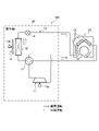
- FIG. 1 is a configuration diagram of an air conditioner 100 according to the first embodiment.
- the solid arrows in FIG. 1 indicate the flow of refrigerant during heating operation.
- dashed arrows in FIG. 1 indicate the flow of the refrigerant during the cooling operation.
- the air conditioner 100 is a device that performs air conditioning such as cooling operation and heating operation. As shown in FIG. 1, the air conditioner 100 includes a compressor 11, an outdoor heat exchanger 12, an outdoor fan 13, and an expansion valve .
- the air conditioner 100 also includes an indoor heat exchanger 15 (heat exchanger), an indoor fan 16 (fan), and a four-way valve 17 in addition to the above-described configuration.
- the compressor 11 is a device that compresses a low-temperature, low-pressure gas refrigerant and discharges it as a high-temperature, high-pressure gas refrigerant, and includes a compressor motor 11a as a drive source.
- a compressor 11 a scroll compressor, a rotary compressor, or the like is used.
- an accumulator 9 is connected to the suction side of the compressor 11 for separating gas and liquid of the refrigerant.
- the outdoor heat exchanger 12 is a heat exchanger that exchanges heat between the refrigerant flowing through its heat transfer tubes 12 b (see FIG. 3 ) and the outside air sent by the outdoor fan 13 .
- the outdoor fan 13 is a fan that sends outside air to the outdoor heat exchanger 12 .
- the outdoor fan 13 is provided near the outdoor heat exchanger 12 and has an outdoor fan motor 13a as a drive source.
- the expansion valve 14 is a valve that reduces the pressure of the refrigerant condensed in the "condenser" (one of the outdoor heat exchanger 12 and the indoor heat exchanger 15). The refrigerant decompressed by the expansion valve 14 is guided to an "evaporator" (the other of the outdoor heat exchanger 12 and the indoor heat exchanger 15).
- the indoor heat exchanger 15 is a heat exchanger in which heat is exchanged between the refrigerant flowing through the heat transfer pipes 15b (see FIG. 2) and the indoor air (air-conditioned room air) sent by the indoor fan 16. is.
- the indoor fan 16 is a fan that sends indoor air to the indoor heat exchanger 15 .
- the indoor fan 16 includes an indoor fan motor 16 a (see FIG. 4 ) as a drive source, and is provided near the indoor heat exchanger 15 .
- the four-way valve 17 is a valve that switches the refrigerant flow path according to the operation mode of the air conditioner 100 .
- the air conditioner 100 includes a refrigerant circuit 10 in which a compressor 11, an outdoor heat exchanger 12, an expansion valve 14, and an indoor heat exchanger 15 are connected via a four-way valve 17. It has become.
- the compressor 11, the outdoor heat exchanger 12, the outdoor fan 13, the expansion valve 14, and the four-way valve 17 are installed in the outdoor unit 30.
- the indoor heat exchanger 15 and the indoor fan 16 are installed in the indoor unit 20 .
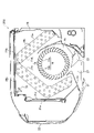
- FIG. 2 is a longitudinal sectional view of the indoor unit 20.
- the indoor unit 20 includes an indoor heat exchanger 15 and an indoor fan 16, as well as a drain pan 18, a housing 19, and filters 21a and 21b.
- the indoor unit 20 includes a front panel 22 , a left/right wind direction plate 23 and an up/down direction plate 24 .
- the indoor heat exchanger 15 includes a plurality of fins 15a and a plurality of heat transfer tubes 15b passing through these fins 15a. From another point of view, the indoor heat exchanger 15 includes a front indoor heat exchanger 15c arranged on the front side of the indoor fan 16, a rear indoor heat exchanger 15d arranged on the rear side of the indoor fan 16, It has In the example of FIG. 2, the upper end portion of the front indoor heat exchanger 15c and the upper end portion of the rear indoor heat exchanger 15d are connected in an inverted V shape when viewed in vertical cross section. Note that the configuration of the indoor heat exchanger 15 shown in FIG. 2 is an example, and the configuration is not limited to this.
- the indoor fan 16 is, for example, a cylindrical cross-flow fan, and is arranged near the indoor heat exchanger 15 .
- the indoor fan 16 includes, in addition to the indoor fan motor 16a (see FIG. 4), a plurality of fan blades 16b and an annular partition plate 16c on which the fan blades 16b are installed.
- the drain pan 18 receives condensed water from the indoor heat exchanger 15 and is arranged below the indoor heat exchanger 15 .
- the housing 19 accommodates the indoor heat exchanger 15, the indoor fan 16, and the like.
- the filters 21 a and 21 b collect dust from the air heading for the indoor heat exchanger 15 and are arranged near the indoor heat exchanger 15 .
- One filter 21 a is arranged in front of the indoor heat exchanger 15
- the other filter 21 b is arranged above the indoor heat exchanger 15 .
- the front panel 22 is a panel installed so as to cover the front filter 21a, and is rotatable forward about its lower end. In addition, the structure which the front panel 22 does not rotate may be sufficient.
- the left/right wind direction plate 23 is a plate-like member that adjusts the left/right direction of the air blown out from the indoor fan 16 .
- the left/right airflow direction plate 23 is arranged in the blowing air passage 26, and is rotated in the left/right direction by a left/right direction plate motor 34 (see FIG. 4).
- the vertical wind direction plate 24 is a plate-shaped member that adjusts the vertical direction of the air blown out from the indoor fan 16 .
- the vertical wind direction plate 24 is arranged at the air outlet 27 and is rotated vertically by a vertical wind direction plate motor 35 (see FIG. 4).
- the air sucked in through the air inlets 25 a and 25 b exchanges heat with the refrigerant flowing through the heat transfer tubes 15 b of the indoor heat exchanger 15 , and the heat-exchanged air is led to the blowout air passage 26 .
- the air flowing through the blowing air passage 26 is guided in a predetermined direction by the horizontal airflow direction plate 23 and the vertical airflow direction plate 24, and is further blown out through the air outlet 27 into the air conditioning room.
- the indoor heat exchanger 15 after the temperature of the indoor heat exchanger 15 is raised to soften (or liquefy/fluidize) the oil on the surface of the indoor heat exchanger 15, the indoor heat exchanger 15 is frozen and thawed. are sequentially performed, the oil on the surface of the indoor heat exchanger 15 is washed away together with the dust.
- a series of processes including heating, freezing, and thawing of the indoor heat exchanger 15 is called "cleaning operation".
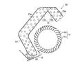
- FIG. 3 is a perspective view of the housing 31 of the outdoor unit 30 with the side plates and top plate removed. 3, illustration of the expansion valve 14 (see FIG. 1) and the four-way valve 17 (see FIG. 1) is omitted.
- a housing 31 of the outdoor unit 30 is provided with a compressor 11 , an outdoor heat exchanger 12 , an outdoor fan 13 , and an electric component box 32 .
- the outdoor heat exchanger 12 having an L-shape in plan view is installed on the bottom plate 31 a of the housing 31 .
- the outdoor heat exchanger 12 includes a large number of fins 12a arranged at predetermined intervals and a plurality of heat transfer tubes 12b passing through the fins 12a.
- a propeller fan is used as the outdoor fan 13 .
- FIG. 4 is a functional block diagram of the air conditioner 100. As shown in FIG. In addition to the components described above, the indoor unit 20 shown in FIG. An indoor control circuit 41 is provided.
- the remote controller transmitting/receiving unit 28 exchanges predetermined information with the remote controller 50 by infrared communication or the like.
- the indoor temperature sensor 29 is a sensor that detects the temperature of the air-conditioned room, and is installed, for example, on the air intake side of the indoor heat exchanger 15 .
- the indoor heat exchanger temperature sensor 33 is a sensor that detects the temperature of the indoor heat exchanger 15 (see FIG. 2).
- the indoor heat exchanger temperature sensor 33 may be installed in the indoor heat exchanger 15 or may be installed in a predetermined refrigerant pipe connected to the indoor heat exchanger 15 .
- the detected values of the indoor temperature sensor 29 and the indoor heat exchanger temperature sensor 33 are output to the indoor control circuit 41 .
- the display lamp 36 is a lamp that provides a predetermined display regarding air conditioning.
- the indoor control circuit 41 includes electronic circuits such as a CPU (Central Processing Unit), ROM (Read Only Memory), RAM (Random Access Memory), and various interfaces. Then, the program stored in the ROM is read out and developed in the RAM, and the CPU executes various processes.
- a CPU Central Processing Unit
- ROM Read Only Memory
- RAM Random Access Memory
- the indoor control circuit 41 includes a storage section 41a and an indoor control section 41b.
- the storage unit 41a stores data received via the remote control transmission/reception unit 28, detection values of each sensor, and the like.
- the indoor control unit 41b controls the indoor fan motor 16a, the left/right air deflector motor 34, the up/down air deflector motor 35, the display lamp 36, and the like based on the data in the storage unit 41a.
- the outdoor unit 30 includes an outdoor temperature sensor 37 and an outdoor control circuit 42 in addition to the above configuration.
- the outdoor temperature sensor 37 is a sensor that detects the temperature of outside air, and is installed at a predetermined location of the outdoor unit 30 .
- the outdoor unit 30 also includes a sensor for detecting the discharge temperature of the compressor 11 (see FIG. 1). Detected values of these sensors are output to the outdoor control circuit 42 .
- the outdoor control circuit 42 includes electronic circuits such as a CPU, ROM, RAM, and various interfaces, and is connected to the indoor control circuit 41 via a communication line. As shown in FIG. 4, the outdoor control circuit 42 includes a storage section 42a and an outdoor control section 42b.
- the storage unit 42a stores data received from the indoor control circuit 41 in addition to a predetermined program.
- the outdoor control unit 42b controls the compressor motor 11a, the outdoor fan motor 13a, the expansion valve 14, the four-way valve 17, etc. based on the data in the storage unit 42a.
- the indoor control circuit 41 and the outdoor control circuit 42 are collectively referred to as a control unit 40 .
- FIG. 5 is a flowchart relating to the cleaning operation of the indoor heat exchanger (see FIGS. 1 and 4 as needed). Although omitted in FIG. 5, for example, when the value obtained by integrating the execution time of the air conditioning operation from the end of the previous cleaning operation (the sum) reaches a predetermined value, the series shown in FIG. may be started. Further, for example, when a user performs a predetermined operation on an operation terminal such as a remote control 50 (see FIG. 4), a smart phone, or a mobile phone, the series of processes shown in FIG. 5 may be started.
- a remote control 50 see FIG. 4
- a smart phone or a mobile phone
- step S101 of FIG. 5 the control unit 40 heats the indoor heat exchanger 15. That is, the controller 40 performs control to increase the temperature of the indoor heat exchanger 15 .
- control for example, the control unit 40 circulates the refrigerant in the heating cycle in the refrigerant circuit 10 and causes the indoor heat exchanger 15 to function as a condenser.
- the oil adhering to the surfaces of the fins 15a (see FIG. 2) and the heat transfer tubes 15b (see FIG. 2) of the indoor heat exchanger 15 is softened (or liquefied/fluidized).
- the control unit 40 prior to the process (S102) of freezing the indoor heat exchanger 15 (heat exchanger), the control unit 40 performs control (S101) to raise the temperature of the indoor heat exchanger 15. This is one of the main features of one embodiment.
- step S102 the controller 40 freezes the indoor heat exchanger 15. That is, the control unit 40 circulates the refrigerant in the cooling cycle in the refrigerant circuit 10 , causes the indoor heat exchanger 15 (heat exchanger) to function as an evaporator, and freezes the indoor heat exchanger 15 .
- step S103 the controller 40 defrosts the indoor heat exchanger 15.
- the controller 40 stops the compressor 11 and increases the opening of the expansion valve 14 .
- the high-temperature refrigerant flows from the outdoor heat exchanger 12 on the high pressure side to the indoor heat exchanger 15 on the low pressure side via the expansion valve 14, so that the indoor heat exchanger 15 is thawed.
- FIG. 6 is an explanatory diagram showing the state of the indoor heat exchanger 15 during thawing.
- the indoor heat exchanger 15 is frozen (S102 in FIG. 5)
- the controller 40 thaws the indoor heat exchanger 15 (S103)
- high-temperature refrigerant flows through the heat transfer tubes 15b of the indoor heat exchanger 15.
- the frost 61 on the indoor heat exchanger 15 melts, and a large amount of water 62 runs down the drain pan 18 along the fins 15a.
- the controller 40 heats the indoor heat exchanger 15 (S101). This softens (or liquefies/fluidizes) the oil on the surface of the indoor heat exchanger 15 .
- the oil that has been oxidized and adhered is also softened by being heated. After that, the indoor heat exchanger 15 is frozen and thawed, so that the oil is washed away together with the dust 63 adhering to the indoor heat exchanger 15 .
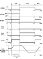
- FIG. 7 is a time chart showing the state of the compressor and the four-way valve, the degree of opening of the expansion valve, the rotation speed of the indoor fan and the outdoor fan, and the temperature change of the indoor heat exchanger (as appropriate, FIG. 1, FIG. 4).
- the horizontal axis of FIG. 7 is time.
- the vertical axis in FIG. 7 indicates the states of the compressor 11, the four-way valve 17, and the like.
- the air conditioner 100 is in a stopped state (a state in which the air conditioning operation is not performed) until time t1. Further, it is assumed that, for example, the cooling operation was being performed immediately before the air conditioner 100 was stopped (see the state of "four-way valve" in FIG. 7).
- the dehumidifying operation or the heating operation may be performed in addition to the cooling operation immediately before the air conditioning operation is stopped.
- the controller 40 When heating the indoor heat exchanger 15 (S101 in FIG. 5), the controller 40 switches the four-way valve 17 to the heating cycle at time t1, throttles the expansion valve 14 to a predetermined opening ⁇ 1, and drives the compressor 11.
- the indoor heat exchanger 15 functions as a condenser
- the outdoor heat exchanger 12 functions as an evaporator.
- the high-temperature refrigerant flows through the indoor heat exchanger 15, so the softening of the oil adhering to the surface of the indoor heat exchanger 15 progresses.
- the controller 40 drives the indoor fan 16 while the indoor heat exchanger 15 is heating (time t1 to t2). This facilitates heat exchange between the refrigerant flowing through the indoor heat exchanger 15 (condenser) and the air in the air-conditioned room. Therefore, it is possible to prevent the pressure of the refrigerant in the indoor heat exchanger 15 from becoming too high, which in turn prevents the discharge pressure of the compressor 11 from becoming too high.
- the control unit 40 rotates the indoor fan 16 in the same direction as during normal air conditioning operation.
- Drive forward rotation
- the "lower limit” mentioned above is the lower limit of the rotation speed of the indoor fan 16 when the controller 40 drives the compressor 11 during the air conditioning operation.
- This “lower limit value” does not include the state where the indoor fan 16 is stopped (that is, 0 [min ⁇ 1 ]).
- the control unit 40 drives the indoor fan 16 at a relatively low speed, thereby reducing the amount of air when the oil-smelling air is blown into the air-conditioned room.
- the control unit 40 may cause the up/down wind direction plate 24 (see FIG. 2) to face upward from the horizontal direction. preferable.
- the state in which the up/down wind direction plate 24 is closed is also included in the matter that the up/down direction plate 24 faces upward from the horizontal direction.
- the controller 40 drives the indoor fan 16 and the outdoor fan 13 as well.
- a balance can be achieved between the heat radiation from the refrigerant to the air in the indoor heat exchanger 15 (condenser) and the heat absorption from the air to the refrigerant in the outdoor heat exchanger 12 (evaporator).
- This predetermined value Ta is a temperature threshold that serves as a criterion for determining whether softening of the oil on the surface of the indoor heat exchanger 15 is likely to progress, and is set in advance.
- the predetermined value Ta may be set to 40° C., for example. Then, in the control for increasing the temperature of the indoor heat exchanger 15 (heat exchanger), the control unit 40 may keep the temperature of the indoor heat exchanger 15 at 40° C. or higher for a predetermined time. .
- the above-mentioned predetermined time (predetermined time ⁇ t in the example of FIG. 7) is a time sufficient for the oil adhering to the indoor heat exchanger 15 to completely melt, and is set in advance.
- the predetermined time ⁇ t is preferably shorter than the time during which the indoor heat exchanger 15 is frozen (time t3 to t4 in FIG. 7). As a result, it is possible to prevent the indoor heat exchanger 15 from being heated for an unnecessarily long time, thereby improving the user's comfort and reducing the power consumption of the air conditioner 100 .
- the time t2 to t3 after heating the indoor heat exchanger 15 is a predetermined balance period.
- the controller 40 stops the compressor 11, switches the four-way valve 17 to the cooling cycle, and increases the opening of the expansion valve 14 (for example, fully open).
- the opening of the expansion valve 14 for example, fully open.
- control unit 40 controls the temperature of the indoor heat exchanger 15 from the end of the control to increase the temperature of the indoor heat exchanger 15 (time t2 in FIG. 7) to the start of the process of freezing the indoor heat exchanger 15 (time t3). It is preferable to put the indoor fan 16 into a stopped state. In this way, by stopping the indoor fan 16 during the predetermined balance period (time t2 to t3), it is possible to reduce the user's sense of discomfort due to noise and the like, and to reduce the power consumption of the air conditioner 100.
- control unit 40 preferably starts the process of freezing the indoor heat exchanger 15 before a predetermined time has elapsed from the end of the control for raising the temperature of the indoor heat exchanger 15 (time t2).
- time t2 a predetermined time has elapsed from the end of the control for raising the temperature of the indoor heat exchanger 15
- the predetermined time (for example, 1 hour) is the time required for the softened oil to harden and return to its original state when left at normal temperature, and is set in advance.
- the controller 40 restricts the expansion valve 14 to a predetermined degree of opening ⁇ 2 at time t3 in FIG.
- the predetermined opening degree ⁇ 2 may be, for example, an opening degree smaller than that during normal air-conditioning operation. Further, while the indoor heat exchanger 15 is frozen, the four-way valve 17 is maintained in the cooling cycle.
- the outdoor heat exchanger 12 functions as a condenser
- the indoor heat exchanger 15 functions as an evaporator.
- low-pressure refrigerant with a saturation temperature lower than 0° C. flows into the indoor heat exchanger 15, so that moisture in the air frosts and freezes on the indoor heat exchanger 15.
- the control unit 40 keeps the state in which the detected value of the indoor heat exchanger temperature sensor 33 (see FIG. 4) is below freezing for a predetermined time.
- the controller 40 stops the indoor fan 16 while the indoor heat exchanger 15 is frozen (time t3 to t4). This can prevent cold air from blowing into the air conditioning room. Further, in the example of FIG. 7, the controller 40 drives the outdoor fan 13 while the indoor heat exchanger 15 is frozen (time t3 to t4). As a result, it is possible to prevent the pressure of the refrigerant in the outdoor heat exchanger 12 from becoming too high, and consequently to prevent the discharge pressure of the compressor 11 from becoming too high.
- the controller 40 After freezing the indoor heat exchanger 15 in this manner, the controller 40 thaws the indoor heat exchanger 15 (S103 in FIG. 5). That is, at time t4, the control unit 40 stops the compressor 11 and the outdoor fan 13, maintains the indoor fan 16 in a stopped state, and increases the opening degree of the expansion valve 14 (for example, fully opens the expansion valve 14). do). As a result, high-temperature refrigerant flows from the outdoor heat exchanger 12 on the high pressure side into the indoor heat exchanger 15 on the low pressure side via the expansion valve 14 . As a result, the frost and ice on the indoor heat exchanger 15 are melted, and the dust and oil are washed away from the indoor heat exchanger 15 (see FIG. 6).
- FIG. 7 is an example, and the control of each device in the cleaning operation of the indoor heat exchanger 15 is not limited to this.
- the rotation speed of the compressor 11 and the opening degree of the expansion valve 14 may be appropriately changed.
- the control unit 40 controls to raise the temperature of the indoor heat exchanger 15 (S101 in FIG. 5), thereby softening the oil adhered to the indoor heat exchanger 15. After softening the oil on the surfaces of the indoor heat exchangers 15 in this manner, the controller 40 sequentially freezes and thaws the indoor heat exchangers 15 (S102 and S103 in FIG. 5). As a result, the oil on the surface of the indoor heat exchanger 15 is washed away together with the dust by the water caused by freezing. Therefore, the indoor heat exchanger 15 can be kept clean. Moreover, the heat exchange efficiency between the refrigerant and the air in the indoor heat exchanger 15 can be enhanced.
- the second embodiment differs from the first embodiment in that the indoor unit 20A (see FIG. 8) is provided with a heater 71 (see FIG. 8) and the indoor heat exchanger 15 is heated by the heater 71. .
- Other points are the same as in the first embodiment. Therefore, the portions different from the first embodiment will be described, and the description of the overlapping portions will be omitted.
- FIG. 8 is a longitudinal sectional view of an indoor unit 20A included in an air conditioner according to the second embodiment.
- the indoor unit 20A includes a heater 71 in addition to the configuration described in the first embodiment (see FIG. 2).
- the heater 71 is, for example, an electric heater that is appropriately energized during the heating operation to assist in heating the air.
- the heater 71 also has a function of increasing the temperature of the indoor heat exchanger 15 and softening the oil on its surface by being energized prior to the freezing of the indoor heat exchanger 15 .
- the heater 71 is provided near the indoor heat exchanger 15 (heat exchanger) inside the housing 19 .
- a heater 71 is provided inside the rear indoor heat exchanger 15d (on the downstream side of the air flow).
- the heater 71 elongates in parallel with the axial direction of the indoor fan 16 .
- the heater 71 may be installed in the front indoor heat exchanger 15c instead of the rear indoor heat exchanger 15d.
- a heater 71 may be installed in each of the front indoor heat exchanger 15c and the rear indoor heat exchanger 15d.
- FIG. 9 is a functional block diagram of an air conditioner 100A according to the second embodiment.
- the heater 71 is connected to the indoor control circuit 41 via wiring. Then, the heater 71 is energized in a predetermined manner according to a command from the indoor controller 41b (that is, the controller 40).
- FIG. 10 is a time chart showing the state of the compressor and the four-way valve, the degree of opening of the expansion valve, the rotation speed of the indoor fan and the outdoor fan, the state of the heater, and the temperature change of the indoor heat exchanger. 1 and 9).
- the controller 40 turns on the heater 71 during the time t1 to t2 when the indoor heat exchanger 15 is heated. That is, the control unit 40 energizes the heater 71 in the control for increasing the temperature of the indoor heat exchanger 15 (heat exchanger). Since the indoor heat exchanger 15 is made of metal, the temperature rises not only at the location where the heater 71 is installed (see FIG. 8) but also in substantially the entire area of the indoor heat exchanger 15 . As a result, the oil on the surface of the indoor heat exchanger 15 is softened (or liquefied/fluidized).
- the compressor 11, the indoor fan 16, and the outdoor fan 13 are stopped while the indoor heat exchanger 15 is heating. If the indoor heat exchanger 15 can be sufficiently heated by the heater 71, the compressor 11 and the like may be stopped in this way. During heating of the indoor heat exchanger 15 by the heater 71, the control unit 40 may circulate the refrigerant in the heating cycle, or may drive the indoor fan 16 appropriately.
- the controller 40 After heating the indoor heat exchanger 15 with the heater 71, the controller 40 causes the indoor heat exchanger 15 to function as an evaporator and freeze the indoor heat exchanger 15 at times t2 to t3 in FIG. In addition, since the processing during freezing of the indoor heat exchanger 15 is the same as that of the first embodiment, the description thereof is omitted. While the indoor heat exchanger 15 is frozen, the heater 71 is turned off so as not to increase the temperature of the indoor heat exchanger 15 .
- the controller 40 After freezing the indoor heat exchanger 15, the controller 40 stops the compressor 11 from time t3 and increases the opening of the expansion valve 14 (for example, fully open). As a result, the high-temperature refrigerant flows into the indoor heat exchanger 15, so the frost on the indoor heat exchanger 15 melts. In addition, when the indoor heat exchanger 15 is thawed, it is not essential to increase the opening degree of the expansion valve 14 , and it is sufficient if the refrigerant flows through the expansion valve 14 . Moreover, it is preferable that the controller 40 energizes the heater 71 after performing the process of freezing the indoor heat exchanger 15 . For example, while the indoor heat exchanger 15 is being thawed, the controller 40 energizes the heater 71 with the expansion valve 14 fully open.
- the controller 40 before the indoor heat exchanger 15 is frozen, the controller 40 energizes the heater 71 to soften the oil on the surface of the indoor heat exchanger 15 . After that, the indoor heat exchanger 15 is sequentially frozen and thawed, so that the oil on the surface of the indoor heat exchanger 15 is washed away together with the dust. In addition, when the controller 40 energizes the heater 71 while the indoor heat exchanger 15 is thawing, oil clogging of the drainage groove (not shown) of the drain pan 18 and the drain pipe (not shown) can be suppressed.
- the third embodiment is different from the first embodiment in that the indoor unit 20B (see FIG. 11) is provided with an ultrasonic irradiation device 72 (see FIG. 11), and the indoor heat exchanger 15 is heated by ultrasonic waves. different. Other points are the same as in the first embodiment. Therefore, the portions different from the first embodiment will be described, and the description of the overlapping portions will be omitted.
- FIG. 11 is a longitudinal sectional view of an indoor unit 20B provided in an air conditioner according to the third embodiment.
- the indoor unit 20B includes an ultrasonic wave irradiator 72 in addition to the configuration described in the first embodiment (see FIG. 2).
- the ultrasonic irradiator 72 has the function of irradiating the indoor heat exchanger 15 with ultrasonic waves, increasing the temperature of the indoor heat exchanger 15, and softening (or liquefying/fluidizing) the oil on the surface thereof. .
- the ultrasonic irradiator 72 is provided near the indoor heat exchanger 15 (heat exchanger) inside the housing 19 .
- an ultrasonic wave irradiator 72 is installed near the connection point of the filters 21a and 21b.
- the ultrasonic radiator 72 extends in parallel to the axial direction of the indoor fan 16 and faces the indoor heat exchanger 15 (in the example of FIG. 11, the front indoor heat exchanger 15c).
- the ultrasonic waves emitted from the ultrasonic irradiator 72 are applied to the front indoor heat exchanger 15c, and are reflected by the inner wall surfaces of the housing 19, the front panel 22, etc., and the rear indoor heat exchanger. 15d is also irradiated.
- FIG. 12 is a functional block diagram of an air conditioner 100B according to the third embodiment.
- the ultrasonic generator 72 is connected to the indoor control circuit 41 via wiring. Then, according to a command from the indoor control unit 41b (that is, the control unit 40), the ultrasonic waves are emitted from the ultrasonic wave irradiator 72 in a predetermined manner.
- the ON/OFF timing of the ultrasonic irradiation device 72 by the control unit 40 is the same as the control of the heater 71 described in the second embodiment (see FIG. 10). That is, the control unit 40 causes the ultrasonic wave irradiator 72 to irradiate the indoor heat exchanger 15 with ultrasonic waves in the control for increasing the temperature of the indoor heat exchanger 15 (heat exchanger). As a result, heat is generated in the indoor heat exchanger 15, and the oil on the surface of the indoor heat exchanger 15 is softened. If the indoor heat exchanger 15 can be sufficiently heated by the ultrasonic wave irradiator 72, the compressor 11 and the like may be kept in a stopped state while the indoor heat exchanger 15 is being heated.
- the controller 40 keeps the ultrasonic irradiator 72 in an OFF state so as not to increase the temperature of the indoor heat exchanger 15 .
- the controller 40 may cause the ultrasonic wave irradiator 72 to irradiate the indoor heat exchanger 15 with ultrasonic waves. This not only promotes the thawing of the indoor heat exchanger 15, but also raises the temperature of the water dripping into the drain pan 18 (see FIG. 11). Therefore, oil clogging of the drainage groove (not shown) of the drain pan 18 and the drain pipe (not shown) can be suppressed.
- the control unit 40 prior to freezing the indoor heat exchanger 15, causes the ultrasonic irradiator 72 to irradiate the indoor heat exchanger 15 with ultrasonic waves, and the surface of the indoor heat exchanger 15 soften the oil. Thereafter, freezing and thawing of the indoor heat exchanger 15 are sequentially performed, so that the oil on the surface of the indoor heat exchanger 15 is washed away together with dust by the water accompanying the freezing.
- the fourth embodiment is different from the first embodiment in that an imaging unit 73 is provided in the indoor unit 20C (see FIG. 13), and the indoor heat exchanger 15 is heated, etc. based on the imaging result of the imaging unit 73. is different from In addition, about others, it is the same as that of 1st Embodiment. Therefore, the portions different from the first embodiment will be described, and the description of the overlapping portions will be omitted.
- FIG. 13 is a vertical cross-sectional view of an indoor unit 20C included in an air conditioner according to the fourth embodiment.
- the indoor unit 20C includes an imaging unit 73 in addition to the configuration described in the first embodiment (see FIG. 2).
- the imaging unit 73 is for capturing an image of the air-conditioned room, and is installed in the housing 19 in a predetermined manner.
- the imaging unit 73 is installed between the front panel 22 and the up/down wind direction plate 24 in a vertical cross-sectional view. Further, in order to capture an image of the air-conditioned room, the imaging unit 73 is installed in a state in which it faces downward at a predetermined angle with respect to the horizontal direction.
- FIG. 14 is a functional block diagram of an air conditioner 100C according to the fourth embodiment.
- the imaging unit 73 shown in FIG. 14 includes an imaging device (not shown) such as a CCD sensor (Charge Coupled Device) or a CMOS sensor (Complementary Metal Oxide Semiconductor). It is connected to the.
- the imaging result (image data) of the imaging unit 73 is output to the indoor control circuit 41 .
- the indoor control circuit 41 has a function of detecting people in the air-conditioned room based on the imaging result of the imaging unit 73 .
- the indoor control circuit 41 extracts a person's head, chest, arms, legs, etc. based on the image information input from the imaging unit 73 .
- the imaging unit 73 detects a person based on the extracted positional relationship of each unit.
- the method described above is just an example, and the method of detecting a person is not limited to this.
- the control unit 40 including the indoor control circuit 41 and the outdoor control circuit 42 performs control to raise the temperature of the indoor heat exchanger 15 based on the imaging result of the imaging unit 73 .
- FIG. 15 is a flow chart regarding the cleaning operation of the indoor heat exchanger.
- the control unit 40 determines whether or not the kitchen motion or the dining motion has been detected.
- the "kitchen action” is the action when the person in the room is cooking. When the occupants are cooking in the kitchen, they often reciprocate laterally in the vicinity of the kitchen. Therefore, the control unit 40 determines, for example, that the head height position of the person in the room is within a predetermined range (including the average head height position when the person is standing), If the person is reciprocating in the horizontal direction, it is determined that the person in the room is doing the kitchen action.
- the "dining motion” is the motion when the person in the room is eating.
- the control unit 40 determines, for example, that the height of the head of a person in the room is within a predetermined range (including the average height of the head of a person sitting in the room), If the moving distance of the person's head is equal to or less than a predetermined value, it is determined that the person in the room is performing a dining action.
- step S201 If the kitchen action or the dining action is detected in step S201 (S201: Yes), the process of the control unit 40 proceeds to step S202.
- step S202 the control unit 40 sets the frequency of the cleaning operation of the indoor heat exchanger 15 to be high. That is, the control unit 40 sets the frequency of the cleaning operation accompanied by heating of the indoor heat exchanger 15 higher than when neither the kitchen operation nor the dining operation is detected.
- step S203 the control unit 40 determines whether or not the cumulative time of the air conditioning operation has reached a predetermined value. In other words, the control unit 40 determines whether or not the value obtained by accumulating the execution time of the air conditioning operation from the end of the previous cleaning operation (value obtained by summing) has reached a predetermined value.
- step S203 when the accumulated time of the air conditioning operation reaches the predetermined value (S203: Yes), the process of the control unit 40 proceeds to step S204. Then, the controller 40 sequentially heats the indoor heat exchanger 15 (S204), freezes (S205), and defrosts (S206). Note that the processing of steps S204 to S206 is the same as that of steps S101 to S103 of the first embodiment (see FIG. 5), so description thereof will be omitted.
- step S203 when the accumulated time of the air conditioning operation has not reached the predetermined value (S203: No), the control unit 40 repeats the process of step S203.
- the control unit 40 when the kitchen operation or the dining operation is detected (S201: Yes), the control unit 40 frequently performs the cleaning operation accompanied by the heating of the indoor heat exchanger 15 (S202), so that the indoor heat exchange The container 15 can be kept clean. That is, even when oil smoke floating in the air due to cooking or eating adheres to the indoor heat exchanger 15, the oil is softened by the heating of the indoor heat exchanger 15, and is washed away together with the dust by freezing and thawing.
- step S201 when neither the kitchen motion nor the dining motion is detected (S201: No), the control unit 40 proceeds to step S203. Then, in step S203, when the cumulative time of the air conditioning operation reaches the predetermined value (S203: Yes), the control unit 40 performs the cleaning operation of the indoor heat exchanger 15 that involves heating at a normal frequency. Note that regardless of whether or not the kitchen operation or the dining operation is detected, there will be a period of time between the current cleaning operation involving heating of the indoor heat exchanger 15 and the next cleaning operation involving heating. Operation (freezing/thawing) may be performed as appropriate.
- the control unit 40 performs control to increase the temperature of the indoor heat exchanger 15 based on the imaging result of the imaging unit 73, and then freezes the indoor heat exchanger 15 or the like.
- the oil can be softened by heating the indoor heat exchanger 15 and washed away together with the dust.
- the oil that has been oxidized and adhered is softened by heating, and the indoor heat exchanger 15 is frozen and thawed, so that the oil is washed away together with the dust.
- the fifth embodiment differs from the first embodiment in that an indoor unit 20D (see FIG. 16) is provided with a filter cleaning section 74 (see FIG. 16). Further, the fifth embodiment differs from the first embodiment in that the frequency of cleaning operation accompanied by heating of the indoor heat exchanger 15 is lower than the frequency of cleaning the filters 21a and 21b (see FIG. 16). there is In addition, about others, it is the same as that of 1st Embodiment. Therefore, the portions different from the first embodiment will be described, and the description of the overlapping portions will be omitted.
- FIG. 16 is a perspective view of the filters 21a and 21b and the filter cleaning section 74 provided in the indoor unit 20D of the air conditioner according to the fifth embodiment.
- the indoor unit 20D includes a movable filter cleaning section 74 that cleans the filters 21a and 21b.
- the filter cleaning section 74 includes a frame 74a, a filter cleaning brush 74b, and a filter cleaning motor (not shown).
- the frame 74a has an inverted L shape and is arranged outside the filters 21a and 21b.
- the filter cleaning brush 74b is a brush for scraping dust adhering to the filters 21a and 21b, and is installed inside the frame 74a.
- a filter cleaning motor (not shown) is a driving source for laterally moving the frame 74a. When the filter cleaning motor is driven, the frame 74a moves in the width direction, and dust on the surfaces of the filters 21a and 21b is scraped off by the filter cleaning brush 74b.
- control unit 40 controls the frequency of control for increasing the temperature of the indoor heat exchanger 15 (heat exchanger) in the cleaning operation to be lower than the frequency of cleaning the filters 21a and 21b by the filter cleaning unit 74. . In this way, by reducing the frequency of heating the indoor heat exchanger 15, it is possible to reduce the user's discomfort and sense of incongruity associated with blowing hot air into the air-conditioned room.
- the controller 40 makes the frequency of the cleaning operation involving heating of the indoor heat exchanger 15 lower than the frequency of cleaning the filters 21a and 21b. As a result, it is possible to reduce the user's discomfort and sense of incongruity caused by the blowing of warm air into the air-conditioned room.
- the sixth embodiment differs from the first embodiment in that instead of the indoor heat exchanger 15 (see FIG. 1), the outdoor heat exchanger 12 is sequentially heated, frozen, and thawed. Others (configuration of the air conditioner, etc.: see FIGS. 1 to 4) are the same as those of the first embodiment. Therefore, the portions different from the first embodiment will be described, and the description of the overlapping portions will be omitted.
- FIG. 17 is a flowchart relating to the cleaning operation of the outdoor heat exchanger in the air conditioner according to the sixth embodiment (see FIGS. 1 and 4 as appropriate).
- the series shown in FIG. process is started.
- the series of processes shown in FIG. 17 may be started when the user performs a predetermined operation on an operation terminal such as the remote control 50 (see FIG. 4).
- oil may adhere to the outdoor heat exchanger 12 depending on the installation environment of the outdoor unit 30 (see FIG. 1).
- the control unit 40 heats the outdoor heat exchanger 12 in step S301. That is, the control unit 40 performs control (S301) to raise the temperature of the outdoor heat exchanger 12 prior to the process (S302) of freezing the outdoor heat exchanger 12 (heat exchanger). For example, the control unit 40 circulates the refrigerant in the cooling cycle in the refrigerant circuit 10 and causes the outdoor heat exchanger 12 to function as a condenser.
- control unit 40 keeps the temperature of the outdoor heat exchanger 12 at 40°C or higher for a predetermined time. As a result, the oil adhering to the outdoor heat exchanger 12 is heated and softened (or liquefied/fluidized). It is assumed that an outdoor heat exchanger temperature sensor (not shown) for detecting the temperature of the outdoor heat exchanger 12 is provided.
- step S302 the controller 40 freezes the outdoor heat exchanger 12. That is, the control unit 40 circulates the refrigerant in the heating cycle in the refrigerant circuit 10 , causes the outdoor heat exchanger 12 (heat exchanger) to function as an evaporator, and freezes the outdoor heat exchanger 12 .
- step S303 the controller 40 defrosts the outdoor heat exchanger 12.
- the controller 40 stops the compressor 11 and increases the opening of the expansion valve 14 .
- the high-temperature refrigerant flows from the indoor heat exchanger 15 on the high pressure side to the outdoor heat exchanger 12 on the low pressure side through the refrigerant pipe.
- the frost and ice on the outdoor heat exchanger 12 are melted, and the dust and oil are washed away.
- FIG. 18 is a time chart showing the state of the compressor and the four-way valve, the degree of opening of the expansion valve, the rotation speed of the indoor fan and the outdoor fan, and the temperature change of the outdoor heat exchanger. It should be noted that before the control for heating the outdoor heat exchanger 12 is performed and immediately before the air-conditioning operation is stopped, in addition to the heating operation, the cooling operation and the dehumidifying operation may be performed. As shown in FIG. 18, from time t1 to t2, the control unit 40 brings the four-way valve 17 into the cooling cycle state, restricts the expansion valve 14 to a predetermined opening degree ⁇ 1, drives the compressor 11, and the outdoor heat exchanger 12 functions as a condenser (S301 in FIG. 17). The outdoor heat exchanger 12 is thereby heated.
- the controller 40 drives the indoor fan 16 at a low speed and also drives the outdoor fan 13 (fan).
- the control unit 40 sets the sum of the upper limit value and the lower limit value of the rotational speed of the indoor fan 16 to 2 during at least a part of the period of control for increasing the temperature of the outdoor heat exchanger 12. It is preferable to drive (forward rotation or reverse rotation) at a rotational speed equal to or lower than the divided value.
- the "lower limit” mentioned above is the lower limit of the rotation speed of the indoor fan 16 when the controller 40 drives the compressor 11 during the air conditioning operation. This “lower limit value” does not include the state where the indoor fan 16 is stopped (that is, 0 [min ⁇ 1 ]).
- the rotation speed of the indoor fan 16 during heating of the outdoor heat exchanger 12 and the rotation speed of the indoor fan 16 during subsequent freezing are not necessarily the same. The same can be said for the outdoor fan 13 as well.
- the control unit 40 switches the four-way valve 17 to the heating cycle (time t2), throttles the expansion valve 14 to a predetermined opening ⁇ 2, drives the compressor 11, and heats the outdoor air.
- the exchanger 12 is made to function as an evaporator (S302 in FIG. 17). As a result, the freezing of the outdoor heat exchanger 12 progresses. In addition, while the outdoor heat exchanger 12 is frozen, the indoor fan 16 and the outdoor fan 13 are driven in a predetermined manner.
- the controller 40 After freezing the outdoor heat exchanger 12, the controller 40 increases the degree of opening of the expansion valve 14 from time t4 to thaw the outdoor heat exchanger 12 (S303 in FIG. 17). As a result, high-temperature refrigerant flows from the indoor heat exchanger 15 on the high-pressure side to the outdoor heat exchanger 12 on the low-pressure side, melting frost and ice on the outdoor heat exchanger 12 and washing away dust and oil.
- the controller 40 softens the oil adhering to the outdoor heat exchanger 12 by performing control to raise the temperature of the outdoor heat exchanger 12 (S301 in FIG. 17). Then, the controller 40 sequentially freezes and thaws the outdoor heat exchanger 12 (S302, S303 in FIG. 17). As a result, the oil adhering to the outdoor heat exchanger 12 is washed away together with the dust by the water accompanying the freezing. Therefore, the outdoor heat exchanger 12 can be kept clean, and the heat exchange efficiency of the outdoor heat exchanger 12 can be improved.
- the seventh embodiment differs from the first embodiment in that the cleaning operation of the indoor heat exchanger 15 and the cleaning operation of the outdoor heat exchanger 12 are continuously performed. Others (configuration of the air conditioner, etc.: see FIGS. 1 to 4) are the same as those of the first embodiment. Therefore, the portions different from the first embodiment will be described, and the description of the overlapping portions will be omitted.
- FIG. 19 is a flowchart relating to the cleaning operation of the indoor heat exchanger and the outdoor heat exchanger in the air conditioner according to the seventh embodiment (see FIGS. 1 and 4 as appropriate).
- the control unit 40 heats the indoor heat exchanger 15 .
- the controller 40 circulates the refrigerant in the heating cycle in the refrigerant circuit 10 and causes the indoor heat exchanger 15 to function as a condenser, thereby raising the temperature of the indoor heat exchanger 15 . This softens the oil on the surface of the indoor heat exchanger 15 .
- step S402 the control unit 40 circulates the refrigerant in the cooling cycle in the refrigerant circuit 10, freezes the indoor heat exchanger 15 (evaporator), and heats the outdoor heat exchanger 12 (condenser). As a result, frost and ice grow on the indoor heat exchanger 15, while the oil on the surface of the outdoor heat exchanger 12 softens.
- step S403 the control unit 40 circulates the refrigerant in the heating cycle in the refrigerant circuit 10, defrosts the indoor heat exchanger 15 (condenser), and freezes the outdoor heat exchanger 12 (evaporator). As a result, oil on the surface of the indoor heat exchanger 15 is washed away together with dust, while frost and ice grow on the outdoor heat exchanger 12 .
- step S404 the control unit 40 defrosts the outdoor heat exchanger 12.
- the controller 40 increases the degree of opening of the expansion valve 14 to allow high-temperature refrigerant to flow from the indoor heat exchanger 15 on the high pressure side to the outdoor heat exchanger 12 on the low pressure side. by this. Oil on the surface of the outdoor heat exchanger 12 is washed away together with dust.
- the control unit 40 ends a series of processes related to the cleaning operation (END).
- the outdoor heat exchanger 12 is also heated while the indoor heat exchanger 15 is frozen (S402 in FIG. 19).
- the outdoor heat exchanger 12 is also frozen (S403 in FIG. 19).
- the controller 40 freezes the indoor heat exchanger 15 and cleans the indoor heat exchanger 15.
- the indoor heat exchanger 15 may be condensed. good.
- the control unit 40 first calculates the dew point of the air based on the detected values of the temperature and humidity of the air-conditioned room. The controller 40 controls the opening degree of the expansion valve 14 and the like so that the temperature of the indoor heat exchanger 15 is equal to or lower than the dew point and higher than the predetermined freezing temperature.
- the “freezing temperature” is the temperature at which moisture contained in the air begins to freeze in the indoor heat exchanger 15 when the temperature of the indoor heat exchanger 15 is lowered. In this way, it is also possible to wash the indoor heat exchanger 15 with the water that accompanies condensation on the indoor heat exchanger 15 . Similarly, in the second to seventh embodiments, the controller 40 may wash the indoor heat exchanger 15 and/or the outdoor heat exchanger 12 (that is, the heat exchanger) with condensed water. .
- control unit 40 drives the indoor fan 16 while the indoor heat exchanger 15 is being heated (time t1 to t2 in FIG. 7) has been described, but the present invention is not limited to this. That is, the control unit 40 may drive the indoor fan 16 (fan) during at least part of the period of control for increasing the temperature of the indoor heat exchanger 15 (heat exchanger). This can prevent the discharge pressure of the compressor 11 from becoming too high.
- the control unit 40 drives the outdoor fan 13 (fan) during at least part of the period of control for increasing the temperature of the outdoor heat exchanger 12 (heat exchanger).
- the control unit 40 directs the vertical wind direction plate 24 upward from the horizontal direction, and rotates the indoor fan 16 forward.
- the control unit 40 may reversely rotate the indoor fan 16 during at least a part of the control period for increasing the temperature of the indoor heat exchanger 15 .
- the reverse rotation of the indoor fan 16 is rotation in the direction opposite to that during normal air conditioning operation. As a result, the air is blown toward the ceiling via the air inlets 25a and 25b (see FIG. 2), so that the heated air can be prevented from hitting the user directly.
- the control unit 40 stops the indoor fan 16 while the indoor heat exchanger 15 is frozen (time t3 to t4 in FIG. 7) has been described, but the present invention is not limited to this. That is, the controller 40 may stop the indoor fan 16 during at least part of the process of freezing (or condensing) the indoor heat exchanger 15 . As a result, cold air can be prevented from being blown into the air-conditioned room while the indoor heat exchanger 15 is frozen. In particular, it is preferable for the controller 40 to stop the indoor fan 16 for a predetermined time from the start of the process of freezing (or condensing) the indoor heat exchanger 15 .
- the temperature of the indoor heat exchanger 15 that has reached a high temperature due to heating can be quickly lowered, and the indoor heat exchanger 15 can be frozen. Further, while the indoor heat exchanger 15 is frozen, the controller 40 may drive the indoor fan 16 at a low speed (rotational speed at which freezing is possible). The same can be said for the second to seventh embodiments.
- the controller 40 controls the indoor heat exchanger 15 (heat It is preferable not to control the temperature of the heat exchanger. As a result, it is possible to prevent the temperature of the air-conditioned room from becoming too high due to the heating of the indoor heat exchanger 15, thereby enhancing comfort for the user.
- the second to seventh embodiments when the detected value of the indoor temperature sensor 29 (see FIG. 4) or the outdoor temperature sensor 37 (see FIG. 4) is equal to or greater than a predetermined value, It is preferable not to perform control to raise the temperature of the heat exchanger 12 (heat exchanger).
- the outdoor heat exchanger 12 is frozen after being heated, high-temperature air that has absorbed heat from the indoor heat exchanger 15 (condenser) can be prevented from blowing out into the room.
- the detected value of the indoor heat exchanger temperature sensor 33 (heat exchanger temperature sensor: see FIG. 4) is already a predetermined value
- the control part 40 starts the above-described process without performing control which raises the temperature of the indoor heat exchanger 15.
- the control unit 40 raises the temperature of the indoor heat exchanger 15.
- the current processing such as freezing may be started without performing the control to allow the freezing.
- the indoor heat exchanger temperature sensor When the detected value of 33 is equal to or higher than a predetermined value, the control unit 40 may start the current processing such as freezing without performing control to raise the temperature of the indoor heat exchanger 15 .
- the freezing of the indoor heat exchanger 15 is started, if the temperature of the indoor heat exchanger 15 is already relatively high (for example, if the heating operation was performed immediately before), the indoor heat exchanger 15 is frozen. This is because there is no particular need for heating. As a result, the time required for cleaning the indoor heat exchanger 15 can be shortened, and the power consumption of the air conditioner 100 can be reduced.
- the control unit 40 controls to raise the temperature of the outdoor heat exchanger 12. Instead, the process of freezing or condensing the outdoor heat exchanger 12 may be started.
- the expansion valve 14 is fully opened (after time t4 in FIG. 7), and the indoor heat exchanger 15 is thawed.
- the indoor heat exchanger 15 is thawed, it is not essential to increase the degree of opening of the expansion valve 14 , and it is sufficient if the refrigerant flows through the expansion valve 14 .
- the controller 40 may circulate the refrigerant in the heating cycle in the refrigerant circuit 10 and cause the indoor heat exchanger 15 to function as a condenser, thereby defrosting the indoor heat exchanger 15 .
- the indoor heat exchanger 15 may be thawed by the controller 40 stopping the compressor 11 and appropriately driving the indoor fan 16 . The same applies to the second to seventh embodiments.
- each embodiment can be appropriately combined.
- the controller 40 causes the indoor heat exchanger 15 to function as a condenser (first embodiment) and energizes the heater 71 (second embodiment). mode), the indoor heat exchanger 15 may be heated.
- the controller 40 causes the indoor heat exchanger 15 to function as a condenser (first embodiment), and emits ultrasonic waves from the ultrasonic wave irradiator 72. You may make it heat the indoor heat exchanger 15 by irradiating (3rd Embodiment).
- a heating method for the indoor heat exchanger 15 all of the first to third embodiments may be combined.
- the second and third embodiments and the sixth embodiment may be combined.
- Other methods may be appropriately used as a method for heating the indoor heat exchanger 15 or the outdoor heat exchanger 12 .
- the control unit 40 when the control unit 40 detects the kitchen operation or the dining operation based on the imaging result of the imaging unit 73 (see FIG. 13) (S201 in FIG. 15: Yes), the frequency of the cleaning operation is set to
- the process of increasing S202
- the present invention is not limited to this.
- the control unit 40 adjusts the frequency of the cleaning operation of the indoor heat exchanger 15, which involves heating. You can make it higher. According to such a configuration, even if cooking oil adheres to the indoor heat exchanger 15, the oil can be softened by heating the indoor heat exchanger 15, and the oil can be washed away with water caused by freezing. .
- the following processing may be performed. That is, in addition to the remote controller 50 (see FIG. 4), information regarding the presence or absence of a kitchen or a dining room may be input based on the user's operation on an "operation terminal" such as a smartphone, mobile phone, tablet, or the like. If the air-conditioned room includes a kitchen or a dining room, the control unit 40 frequently performs the cleaning operation of the indoor heat exchanger 15 that involves heating. In this way, the control unit 40 controls the temperature of the indoor heat exchanger 15 to rise based on the operation of the "operation terminal", thereby keeping the indoor heat exchanger 15 clean.
- an "operation terminal” such as a smartphone, mobile phone, tablet, or the like.
- the control unit 40 may perform the cleaning operation of the indoor heat exchanger 15 that involves heating.
- the indoor heat exchanger 15 is often contaminated with oil.
- the user may operate the "operation terminal" such as the remote control 50 in a predetermined manner to perform the cleaning operation. As a result, oil stains on the indoor heat exchanger 15 are washed away.
- the control unit 40 first controls heating of the indoor heat exchanger 15 in the cleaning operation of the indoor heat exchanger 15 and the outdoor heat exchanger 12 has been described (FIG. 19). ), the following process may alternatively be performed. That is, after performing control to heat the outdoor heat exchanger 12 to a predetermined level, the control unit 40 circulates the refrigerant in the heating cycle to freeze the outdoor heat exchanger 12 (evaporator), while the indoor heat exchanger 15 (condenser) is heated. Then, the control unit 40 circulates the refrigerant in the cooling cycle, defrosts the outdoor heat exchanger 12 (condenser), and freezes the indoor heat exchanger 15 (evaporator). Next, the control unit 40 increases the degree of opening of the expansion valve 14 to defrost the indoor heat exchanger 15, for example. Both the indoor heat exchanger 15 and the outdoor heat exchanger 12 can be cleaned by such treatment.
- each embodiment a configuration in which one indoor unit 20 (see FIG. 1) and one outdoor unit 30 (see FIG. 1) are provided has been described, but the configuration is not limited to this. That is, a plurality of indoor units connected in parallel may be provided, or a plurality of outdoor units connected in parallel may be provided.
- each embodiment can also be applied to package air conditioners and multi air conditioners for buildings.
- each embodiment is described in detail in order to explain the present invention in an easy-to-understand manner, and is not necessarily limited to those having all the described configurations. Moreover, it is possible to add, delete, or replace part of the configuration of each embodiment with another configuration. Further, the mechanisms and configurations described above show those considered necessary for explanation, and do not necessarily show all the mechanisms and configurations on the product.
- refrigerant circuit 11 compressor 12 outdoor heat exchanger (heat exchanger) 13 Outdoor fan (fan) 14 expansion valve 15 indoor heat exchanger (heat exchanger) 16 indoor fan (fan) 17 four-way valve 18 drain pan 19 housing 21a, 21b filter 29 indoor temperature sensor 30 outdoor unit 33 indoor heat exchanger temperature sensor (heat exchanger temperature sensor) 37 outdoor temperature sensor 40 control unit 50 remote controller (operation terminal) 71 heater 72 ultrasonic irradiation device 73 imaging unit 74 filter cleaning unit 100, 100A, 100B, 100C air conditioner
Landscapes
- Engineering & Computer Science (AREA)
- Chemical & Material Sciences (AREA)
- Combustion & Propulsion (AREA)
- Mechanical Engineering (AREA)
- General Engineering & Computer Science (AREA)
- Air Conditioning Control Device (AREA)
- Air Filters, Heat-Exchange Apparatuses, And Housings Of Air-Conditioning Units (AREA)
Priority Applications (4)
| Application Number | Priority Date | Filing Date | Title |
|---|---|---|---|
| CN202180004359.4A CN115210509B (zh) | 2021-02-01 | 2021-02-01 | 空调机 |
| JP2021531438A JP6945100B1 (ja) | 2021-02-01 | 2021-02-01 | 空気調和機 |
| PCT/JP2021/003550 WO2022162942A1 (ja) | 2021-02-01 | 2021-02-01 | 空気調和機 |
| TW111103883A TWI808635B (zh) | 2021-02-01 | 2022-01-28 | 空調機 |
Applications Claiming Priority (1)
| Application Number | Priority Date | Filing Date | Title |
|---|---|---|---|
| PCT/JP2021/003550 WO2022162942A1 (ja) | 2021-02-01 | 2021-02-01 | 空気調和機 |
Publications (1)
| Publication Number | Publication Date |
|---|---|
| WO2022162942A1 true WO2022162942A1 (ja) | 2022-08-04 |
Family
ID=77915152
Family Applications (1)
| Application Number | Title | Priority Date | Filing Date |
|---|---|---|---|
| PCT/JP2021/003550 Ceased WO2022162942A1 (ja) | 2021-02-01 | 2021-02-01 | 空気調和機 |
Country Status (4)
| Country | Link |
|---|---|
| JP (1) | JP6945100B1 (https=) |
| CN (1) | CN115210509B (https=) |
| TW (1) | TWI808635B (https=) |
| WO (1) | WO2022162942A1 (https=) |
Families Citing this family (4)
| Publication number | Priority date | Publication date | Assignee | Title |
|---|---|---|---|---|
| CN114413327A (zh) * | 2021-12-24 | 2022-04-29 | 珠海格力电器股份有限公司 | 空调防凝露控制方法及空调 |
| CN119998596A (zh) * | 2022-11-29 | 2025-05-13 | 三星电子株式会社 | 空调及其控制方法 |
| KR20240079721A (ko) * | 2022-11-29 | 2024-06-05 | 삼성전자주식회사 | 공기 조화기 및 이의 제어 방법 |
| CN115875733B (zh) * | 2022-11-29 | 2024-09-20 | 海信空调有限公司 | 一种空调器及其防油堵控制方法 |
Citations (6)
| Publication number | Priority date | Publication date | Assignee | Title |
|---|---|---|---|---|
| JPH0468251A (ja) * | 1990-07-06 | 1992-03-04 | Mitsubishi Electric Corp | 空気調和機の制御装置 |
| JP2005164068A (ja) * | 2003-11-28 | 2005-06-23 | Sharp Corp | 空気調和機 |
| JP2017116134A (ja) * | 2015-12-22 | 2017-06-29 | 株式会社前川製作所 | 熱交換器及び熱交換器の除霜方法 |
| JP2018200167A (ja) * | 2018-05-29 | 2018-12-20 | 日立ジョンソンコントロールズ空調株式会社 | 空気調和機 |
| JP6587777B1 (ja) * | 2018-05-14 | 2019-10-09 | 日立ジョンソンコントロールズ空調株式会社 | 空気調和機 |
| JP6749507B1 (ja) * | 2019-08-30 | 2020-09-02 | 日立ジョンソンコントロールズ空調株式会社 | 空気調和機 |
Family Cites Families (9)
| Publication number | Priority date | Publication date | Assignee | Title |
|---|---|---|---|---|
| JP2001065958A (ja) * | 1999-08-23 | 2001-03-16 | Osaka Gas Co Ltd | 空気調和装置及びその運転方法 |
| EP3617609A4 (en) * | 2017-04-28 | 2021-03-24 | Hitachi-Johnson Controls Air Conditioning, Inc. | AIR CONDITIONER |
| JP6360593B1 (ja) * | 2017-05-26 | 2018-07-18 | 日立ジョンソンコントロールズ空調株式会社 | 空気調和機 |
| CN110873411A (zh) * | 2018-08-31 | 2020-03-10 | 青岛海尔空调器有限总公司 | 一种空调及其自清洁的控制方法 |
| WO2020070892A1 (ja) * | 2018-10-05 | 2020-04-09 | 日立ジョンソンコントロールズ空調株式会社 | 空気調和機、空気調和機の制御方法およびプログラム |
| CN109751692B (zh) * | 2019-02-25 | 2024-01-16 | 广东澄一科技有限公司 | 一种空调油烟机集成系统 |
| CN110793099B (zh) * | 2019-11-12 | 2024-09-24 | 珠海格力电器股份有限公司 | 具有自清洁功能的室内机、空调系统 |
| JP2021099190A (ja) * | 2019-12-23 | 2021-07-01 | 株式会社富士通ゼネラル | 空気調和装置 |
| CN212204736U (zh) * | 2020-02-28 | 2020-12-22 | 宁波方太厨具有限公司 | 厨房空气调节系统 |
-
2021
- 2021-02-01 WO PCT/JP2021/003550 patent/WO2022162942A1/ja not_active Ceased
- 2021-02-01 JP JP2021531438A patent/JP6945100B1/ja active Active
- 2021-02-01 CN CN202180004359.4A patent/CN115210509B/zh active Active
-
2022
- 2022-01-28 TW TW111103883A patent/TWI808635B/zh active
Patent Citations (6)
| Publication number | Priority date | Publication date | Assignee | Title |
|---|---|---|---|---|
| JPH0468251A (ja) * | 1990-07-06 | 1992-03-04 | Mitsubishi Electric Corp | 空気調和機の制御装置 |
| JP2005164068A (ja) * | 2003-11-28 | 2005-06-23 | Sharp Corp | 空気調和機 |
| JP2017116134A (ja) * | 2015-12-22 | 2017-06-29 | 株式会社前川製作所 | 熱交換器及び熱交換器の除霜方法 |
| JP6587777B1 (ja) * | 2018-05-14 | 2019-10-09 | 日立ジョンソンコントロールズ空調株式会社 | 空気調和機 |
| JP2018200167A (ja) * | 2018-05-29 | 2018-12-20 | 日立ジョンソンコントロールズ空調株式会社 | 空気調和機 |
| JP6749507B1 (ja) * | 2019-08-30 | 2020-09-02 | 日立ジョンソンコントロールズ空調株式会社 | 空気調和機 |
Also Published As
| Publication number | Publication date |
|---|---|
| JPWO2022162942A1 (https=) | 2022-08-04 |
| TWI808635B (zh) | 2023-07-11 |
| CN115210509A (zh) | 2022-10-18 |
| CN115210509B (zh) | 2024-12-03 |
| JP6945100B1 (ja) | 2021-10-06 |
| TW202232032A (zh) | 2022-08-16 |
Similar Documents
| Publication | Publication Date | Title |
|---|---|---|
| JP6400242B1 (ja) | 空気調和機 | |
| JP6349013B1 (ja) | 空気調和機 | |
| JP6945100B1 (ja) | 空気調和機 | |
| JP6387197B1 (ja) | 空気調和機 | |
| TWI707090B (zh) | 空調機 | |
| CN109312932B (zh) | 空调机 | |
| JP6517877B2 (ja) | 空気調和機 | |
| JP2018200167A (ja) | 空気調和機 | |
| JP2002323250A (ja) | 空気調和機 | |
| JP6435443B1 (ja) | 空気調和機 | |
| WO2019043765A1 (ja) | 空気調和機 | |
| JP7626921B2 (ja) | 空気調和装置 | |
| JPWO2019239493A1 (ja) | 空気調和機 | |
| JP7245933B2 (ja) | 空気調和機 | |
| WO2023042297A1 (ja) | 空気調和機および方法 | |
| WO2019234807A1 (ja) | 空気調和機 |
Legal Events
| Date | Code | Title | Description |
|---|---|---|---|
| ENP | Entry into the national phase |
Ref document number: 2021531438 Country of ref document: JP Kind code of ref document: A |
|
| 121 | Ep: the epo has been informed by wipo that ep was designated in this application |
Ref document number: 21922952 Country of ref document: EP Kind code of ref document: A1 |
|
| NENP | Non-entry into the national phase |
Ref country code: DE |
|
| 122 | Ep: pct application non-entry in european phase |
Ref document number: 21922952 Country of ref document: EP Kind code of ref document: A1 |