WO2022162925A1 - 車両用サンルーフ構造 - Google Patents
車両用サンルーフ構造 Download PDFInfo
- Publication number
- WO2022162925A1 WO2022162925A1 PCT/JP2021/003444 JP2021003444W WO2022162925A1 WO 2022162925 A1 WO2022162925 A1 WO 2022162925A1 JP 2021003444 W JP2021003444 W JP 2021003444W WO 2022162925 A1 WO2022162925 A1 WO 2022162925A1
- Authority
- WO
- WIPO (PCT)
- Prior art keywords
- sunroof
- roof
- vehicle
- frame member
- connecting member
- Prior art date
- Legal status (The legal status is an assumption and is not a legal conclusion. Google has not performed a legal analysis and makes no representation as to the accuracy of the status listed.)
- Ceased
Links
Images


Classifications
-
- B—PERFORMING OPERATIONS; TRANSPORTING
- B60—VEHICLES IN GENERAL
- B60J—WINDOWS, WINDSCREENS, NON-FIXED ROOFS, DOORS, OR SIMILAR DEVICES FOR VEHICLES; REMOVABLE EXTERNAL PROTECTIVE COVERINGS SPECIALLY ADAPTED FOR VEHICLES
- B60J7/00—Non-fixed roofs; Roofs with movable panels, e.g. rotary sunroofs
Definitions
- the present invention relates to a vehicle sunroof structure including a sunroof portion provided on a roof of a vehicle, and a first frame member and a second frame member provided to intersect the roof.
- the vehicle roof frame structure described in JP-A-2012-40999 includes a square sunroof unit (sunroof portion) in top view and roof side rails (first frame) extending in the longitudinal direction at both ends in the vehicle width direction. member).
- the sunroof unit is coupled to each roof side rail by brackets provided at the four corners of the sunroof unit.
- a substantially rectangular inner frame that supports the sunroof panel is arranged on the lower surface of the roof panel via a bracket provided on the front side thereof. It is fixed to a roof reinforcement (second frame member) provided and extending in the vehicle width direction.
- the sunroof section is configured so as not to easily resonate with the vibration of the vehicle body. That is, the vibrations transmitted from the road surface and the vibrations of the engine, etc. during running are transmitted to the sunroof portion through the pillars that constitute the vehicle body. At this time, the sunroof section, which resonates with the vibration of the vehicle body, shakes so as to vibrate the surrounding roof panel, which may generate unintended noise (abnormal noise such as muffled noise). Although it is conceivable to additionally install a mass damper on the sunroof to suppress resonance, this would inevitably increase the weight of the vehicle.
- the present invention has been devised in view of the above points, and an object of the present invention is to suppress resonance of the sunroof portion while suppressing an increase in the weight of the vehicle.
- a vehicle sunroof structure of the first invention comprises: a sunroof portion provided on a roof of a vehicle; a first frame member extending in the longitudinal direction of the roof; and a second skeleton member extending in the cross direction of the
- the axial connecting member that connects the sunroof portion to either the first frame member or the second frame member on the imaginary axis passing through the center of gravity of the sunroof portion and the position different from the axial connecting member.
- a connecting member for connecting the sunroof portion to either the first frame member or the second frame member is provided.
- the rigidity of the connecting member by adjusting the rigidity of the connecting member, it is possible to swing the side of the sunroof portion on which the connecting member is not provided with the axial connecting member as a fulcrum so as to suppress resonance. .
- resonance is suppressed by vibration of the sunroof portion, there is no need to separately set a mass damper, and an increase in the weight of the vehicle can be suppressed as much as possible.
- the vehicle sunroof structure of the second invention is the vehicle sunroof structure of the first invention, wherein the sunroof part is separated from another imaginary axis line passing through the center of gravity of the sunroof part so as to intersect the imaginary axis line with the plan view of the roof as a reference. are divided into one side and the other side, the connecting member includes the intersection point between the sunroof portion and the other imaginary axis line, the point located on one side of the intersection point, and the point located on the other side of the intersection point.
- a vehicle sunroof structure is the vehicle sunroof structure of the first aspect or the second aspect, wherein the connection member is provided only on one side of the roof spaced apart from the virtual axis and The other side, which is located on the opposite side and is not provided with the connecting member, is fixed to the first skeleton member or the second skeleton member.
- the other side of the vehicle sunroof structure, which is not provided with a connecting member is fixed and reinforced to the first frame member or the second frame member.
- a vehicle sunroof structure of a fourth invention is the vehicle sunroof structure of any one of the first to third inventions, wherein the axial connection member has higher rigidity than the connection member.
- the axial connection member has higher rigidity than the connection member.
- the resonance of the sunroof portion can be suppressed more reliably.
- the configuration contributes to ensuring the mountability to the roof.
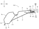
- FIG. 1 is a see-through perspective view of a vehicle;
- FIG. FIG. 3 is a schematic diagram showing a partially exploded roof;
- FIG. 2 is a schematic plan view of the vehicle sunroof structure as viewed from below;
- FIG. 4 is a schematic sectional view of the roof corresponding to the IV-IV line section of FIG. 3;
- FIG. 4 is a schematic enlarged cross-sectional view of the roof showing the roof glass;
- FIG. 4 is a schematic sectional view of the roof corresponding to the VI-VI line section of FIG. 3;
- FIG. 4 is a schematic sectional view of the roof corresponding to the VII-VII line section of FIG. 3;
- FIG. 2 is a schematic plan view of the vehicle sunroof structure showing locations where connecting members are arranged;
- FIG. 1 A mode for carrying out the present invention will be described below with reference to FIGS. 1 to 8.
- FIG. 1 arrows indicating the front-rear direction, the left-right direction, and the up-down direction of the vehicle (roof) are appropriately illustrated, and the left-right direction corresponds to the vehicle width direction. 4 to 7, for the sake of convenience, the main components of the vehicle sunroof structure are illustrated, and the illustration of other members is omitted.
- the roof 3 of the vehicle 2 has a rectangular roof panel 4 that is long in the front-rear direction, roof side rails 5a and 5b that extend in the front-rear direction on both sides in the vehicle width direction, and a plurality of roof reinforcements 6 to 10 that extend in the vehicle width direction. is provided.
- the roof panel 4 gently curves upward toward the rear, and both edges in the vehicle width direction are fixed to roof side rails 5a and 5b.
- each roof side rail 5a and 5b are supported by pillars (12, 13, 14), which are pillars in the front, rear, left, right, and central portions of the vehicle body 11 (for convenience, only the pillars on the left side of the vehicle are shown in FIG. 1). do).
- each roof side rail 5a and the like is formed to have a hollow closed cross section by fixing an inner panel 51 and an outer panel 52 with left and right flanges 53 and 54, respectively.
- An end portion (right end portion in the drawing) of the roof panel 4 in the vehicle width direction is overlapped and fixed to a flange 54 on the inside of the vehicle (left end in FIG. 4) of each roof side rail 5a.
- a plurality of roof reinforcements 6 to 10 shown in FIGS. 1 and 2 are beam-like structures that support the roof panel 4 from below, and are bridged between the left and right roof side rails 5a and 5b.
- the roof 3 of the vehicle 2 is provided with a plurality of (five in each figure) roof reinforcements at appropriate intervals in the longitudinal direction of the vehicle. That is, a pair of front roof reinforcements 6 and 7 are arranged at the front portion of the roof 3 , and a pair of rear roof reinforcements 8 and 9 are arranged at the rear portion of the roof 3 .
- a rear end roof reinforcement 10 is arranged at the rear end of the roof 3 .
- both ends in the longitudinal direction (both ends in the vehicle width direction) of each of the roof reinforcements 6 to 10 are fixed together with the roof panel 4 to the left and right roof side rails 5a, 5b.
- Each of the roof reinforcements 6 to 10 is fixed to the lower surface of the roof panel 4 at both ends in the widthwise direction (both ends in the longitudinal direction of the vehicle).
- the rear roof reinforcement 8 on the front side is formed in the shape of a groove having a substantially U-shaped cross section. 81 and 82 are formed by bending.
- the rear roof reinforcement 8 on the front side is fixed to the roof panel 4 at its flange portions 81 and 82 .
- a rectangular shape extending to the left and right is provided in a range surrounded by the left and right roof side rails 5a, 5b and the front and rear front roof reinforcements 6, 7, a rectangular shape extending to the left and right is provided. is provided with a front opening 3a.
- a front sunroof portion 20 is provided in the front opening portion 3a of the roof panel 4.
- a rectangular rear opening 3b extending in the left and right direction is provided in a range surrounded by left and right roof side rails 5a and 5b and front and rear rear roof reinforcements 8 and 9.
- the rear opening 3b of the roof panel 4 is formed to be larger than the front opening 3a, and is provided with a rear sunroof 30, which will be described later.
- the vehicle sunroof structure SM comprises the rear sunroof portion 30, the left and right roof side rails 5a and 5b, and the front rear roof reinforcement 8.
- the left and right roof side rails 5a and 5b correspond to the first frame member of the present invention
- the front rear roof reinforcement 8 corresponds to the second frame member of the present invention.
- the rear sunroof portion 30 corresponds to the sunroof portion of the present invention, and is connected to the left and right roof side rails 5a and 5b and the front rear roof reinforcement 8 via a plurality of types of connecting members 41 to 44, which will be described later.
- the rear sunroof portion 30 shown in FIG. 1 has a rectangular roof glass 31 elongated in the left and right direction and an opening reinforcement 33, which will be described later, fixed to a receiving portion 32 of the rear opening portion 3b.
- the receiving portion 32 of the rear opening 3b is a portion that is stepped down from the entire circumference of the inner edge of the rear opening 3b, and is formed so that the roof glass 31 can be fitted therein.
- the roof glass 31 is arranged substantially flush with the roof panel 4 with its outer edge fixed to the receiving portion 32 with an adhesive 321 .
- a weather strip 322 is provided between the roof glass 31 and the rear opening 3b (receiving portion 32) to seal the gap.
- a plate-like opening reinforcement 33 fixed to the lower surface of the receiving portion 32 of the roof panel 4 is provided on the periphery of the rear sunroof portion 30, as shown in FIGS.
- the opening reinforcement 33 is formed by forming a right frame portion 311 and a left frame portion 312 extending in the front-rear direction and a front frame portion 313 and a rear frame portion 314 extending in the vehicle width direction into a rectangular shape.
- a left frame portion 312 located on the left side of the rear sunroof portion 30 is fixed to the left receiving portion 32 and protrudes outward (to the left in the figure). It protrudes outward (to the right in the figure) while being fixed to the receiving portion 32 . Further, as shown in FIG.
- the front frame portion 313 positioned at the front portion of the rear sunroof portion 30 projects outward (forward) while being fixed to the front receiving portion 32, and the rear frame portion 313 is positioned at the rear portion.
- the portion 314 also protrudes outward (rearward) while being fixed to the receiving portion 32 on the rear side.
- the rear sunroof portion 30 is provided on the roof 3 so as to be integrated with the roof panel 4 by fixing the roof glass 31 and the opening reinforcement 33 to the receiving portion 32 .
- the rear sunroof portion 30 shown in FIG. 3 is connected to the left and right roof side rails 5a, 5b (first frame members) via left and right axial connecting members 41, 42.
- the left and right axial connecting members 41 and 42 are provided at positions where the center of gravity 300 of the rear sunroof portion 30 can be supported.
- an imaginary axis VL1 passing through the center of gravity 300 of the rear sunroof portion 30 and extending in the vehicle width direction (horizontal direction) is assumed.
- Left and right on-axis coupling members 41 (42) arranged on the imaginary axis VL1 are fixed across the rear sunroof portion 30 and the corresponding roof side rails 5a (5b).
- the center of gravity 300 of the rear sunroof portion 30 is supported by the axial connecting members 41 and 42, and the rear sunroof portion 30 and the left and right roof side rails 5a and 5b (first frame members) are connected. can be done.
- the right axial coupling member 41 and the left axial coupling member 42 shown in FIG. 3 have substantially the same structure except that they are bilaterally symmetrical.
- the right axial coupling member 41 is fixed across the rear sunroof portion 30 and the right roof side rail 5a on the virtual axis VL1.
- the right axial coupling member 41 is gradually inclined downward toward the outside in the vehicle width direction (right side in the drawings), and extends from the front edge, right edge, and rear edge.
- a peripheral flange portion 411 that protrudes outward is formed in the portion of . 4, the left peripheral flange portion 411 of the right axial connecting member 41 is fixed to the right frame portion 311 of the opening reinforcement 33 while being superimposed thereon.
- the left peripheral flange portion 411 is fixed to the inner panel 51 of the right roof side rail 5a while being superimposed thereon.
- the left axial connecting member 42 shown in FIG. 3 is also bridged between the left frame portion 312 of the rear sunroof portion 30 and the left roof side rail 5b so as to be bilaterally symmetrical with the right axial connecting member 41. (In the left shaft connecting member 42 in FIG. 3, for the sake of convenience, the reference numerals of the portions common to the right shaft connecting member 41 are omitted.).
- the left and right axial connecting members 41 and 42 shown in FIG. 3 have higher rigidity than the later-described connecting members 43 and 44 from the viewpoint of securing the attachment (supportability) of the rear sunroof portion 30 to the roof 3. is desirable.
- the dimension in the width direction perpendicular to the bridging direction may be relatively increased, or a relatively high-rigidity material may be used.
- the right shaft coupling member 41 may be formed in a box shape projecting downward, or may be provided with a reinforcing structure such as a bead-shaped recessed portion 412. can also increase rigidity.
- the rear sunroof portion 30 shown in FIG. 3 is connected to the front rear roof reinforcement 8 (second frame member) via a plurality of or a single connecting member (43, 44).
- the connecting members (43, 44) are provided at different positions from the on-axis connecting members 41, 42 in order to cause the rear sunroof portion 30 to swing, which will be described later.
- another imaginary axis line VL2 extending in the longitudinal direction (intersecting direction) passing through the center of gravity 300 of the rear sunroof portion 30 is assumed with reference to the plan view of the roof 3 shown in FIG. do.
- the rear sunroof portion 30 is divided into a right side 301 and a left side 302 (one side and the other side) with another imaginary axis line VL2 as a boundary.
- At least one of the intersection point X1 between the rear sunroof portion 30 and the other imaginary axis VL2, the right side point X2 located on the right side of the intersection point X1, and the left side point X3 located on the left side of the intersection point X1. can be provided in one location.
- another imaginary axis line VL2 is provided so as to be orthogonal to the imaginary axis line VL1, so that the connecting members arranged with reference to the other imaginary axis line VL2 are arranged as far away from the on-axis connecting members 41 and 42 as possible. can be kept. Therefore, in this embodiment, as shown in FIG. 3, the rear sunroof portion 30 and the front side are connected by the right front connecting member 43 arranged at the right side X2 and the left front connecting member 44 arranged at the left side X3. and the rear roof reinforcement 8 are connected.
- the connecting member 43 on the front right side and the connecting member 44 on the front left side shown in FIG. 3 have substantially the same structure except for the arrangement position.
- the connecting member 43 on the front right side is bridged and fixed between the rear sunroof portion 30 and the rear roof reinforcement 8 on the front side at the right side portion X2. 3 and 6, the connecting member 43 on the right front side is gradually inclined downward toward the front, and has left and right flange portions 431 and 432 projecting outward at its right and left edges. is formed.
- the left and right flange portions 431 and 432 on the rear side of the connecting member 43 on the front right side are overlapped on the front edge (overhanging end) of the front skeleton portion 313 of the opening reinforcement 33 and fixed.
- front left and right flange portions 431 and 432 are overlapped and fixed to the lower surface of the front rear roof reinforcement 8 .
- the left front connection member 44 shown in FIG. For the left front connecting member 44 in FIG. 3, for the sake of convenience, the reference numerals for the left and right flange portions are omitted).
- the connecting members 43 and 44 are provided only on the front portion side (one side of the vehicle sunroof structure) where the front frame portion 313 of the rear sunroof portion 30 is located, and are separated from the virtual axis VL1. I am letting For this reason, the front side of the rear sunroof portion 30 is appropriately restrained by the connecting members 43 and 44 so as to minimize vertical vibration.
- the rear side (the other side of the vehicle sunroof structure) where the rear frame portion 314 of the rear sunroof portion 30 is located is the side opposite to the front portion and on which the connecting member is not provided.
- the rear portion of the rear sunroof portion 30 is relatively easily swung up and down by adjusting or controlling the rigidity of each of the connecting members 43 and 44 as will be described later.
- the connecting members 43 and 44 as far away from the imaginary straight line VL1 (the axial connecting members 41 and 42) as possible, the rear side of the rear sunroof portion 30 can be more easily swung.
- the rear portion of the rear sunroof portion 30 is integrated with the roof panel 4 as described above, and is fixed to the rear side rear roof reinforcement 9 (second frame member) located behind it. Therefore, the rear portion of the rear sunroof portion 30 can swing up and down while the roof glass 31 can be easily attached to the roof 3 .
- the rigidity of each connecting member 43, 44 can be controlled by adjusting the thickness dimension D (plate thickness), and can also be adjusted by changing the type of material and structure. . Therefore, in this embodiment, the rigidity of each of the connecting members 43 and 44 is adjusted so that the vibration mode (vibration amplitude, phase, etc.) of the rear portion of the rear sunroof portion 30 can be controlled so as to suppress resonance with the vehicle body. It is set so as to cancel the vibration of the rear sunroof part 30 that produces abnormal noise.
- an appropriate swinging aspect of the rear sunroof portion 30 is not uniformly determined, but is selected in consideration of the configuration of the rear sunroof portion 30 and the vehicle as a whole.
- the method of selecting the rigidity of the connecting member is not particularly limited, for example, a plurality of connecting members having different rigidity can be prepared, and the connecting member that reduces the noise generated can be selected from among them. That is, a plurality of rear sunroof portions 30 using connecting members with different rigidity are prepared, and vibration frequencies within a predetermined range are input for each rear sunroof portion 30 . Then, in the vibration frequency (Hz) range where resonance occurs in each rear sunroof portion 30, the intensity (dB) of the generated abnormal noise is measured, and from among these, those with the intensity of abnormal noise below a predetermined target value are selected. Select.
- Hz vibration frequency
- the rear portion of the rear sunroof portion 30 where no connecting member is provided (the other side of the vehicle sunroof structure) is connected on the left and right shafts.
- the members 41 and 42 can be swung up and down using the fulcrums (see white arrows in FIG. 6).
- the swinging aspect of the rear portion of the rear sunroof portion 30 (the rigidity of the connecting members 43 and 44) is adjusted so as to suppress resonance with the vehicle body. It is set so that the shaking of the sunroof part 30 can be canceled. Therefore, when vibrations during running of the vehicle are transmitted to the rear sunroof part 30, the rear side of the rear sunroof part 30 is forcibly shaken up and down so as to suppress resonance together with the roof panel 4 behind it. By suppressing the resonance of the rear sunroof portion 30 due to the deflection of the rear portion of the rear sunroof portion 30 in this way, it is possible to avoid the generation of abnormal noise caused by the resonance as much as possible.
- the vehicle sunroof structure SM since resonance is suppressed by vibration of the rear sunroof portion 30 (rear portion), there is no need to separately set a mass damper, and an increase in the weight of the vehicle 2 can be suppressed as much as possible.
- the vehicle sunroof structure SM becomes an efficient body structure capable of controlling the NV performance, and contributes to weight reduction of the vehicle 2 and optimization of the body structure. Therefore, according to this embodiment, it is possible to suppress resonance of the rear sunroof portion 30 while suppressing an increase in the weight of the vehicle 2 .
- connecting members (43, 44) are provided on or in the vicinity of another imaginary axis VL2 perpendicular to the imaginary axis VL1, and are spaced apart from the on-axis connecting members 41, 42 as much as possible. becomes easier to shake.
- the rear side of the rear sunroof portion 30 (the other side of the vehicle sunroof structure) is reinforced by being fixed to the rear side rear roof reinforcement 9 (second frame member), which contributes to ensuring the attachment to the roof 3. configuration.
- the rear side of the rear sunroof portion 30 can be shaken while ensuring the attachment of the rear sunroof portion 30 more reliably. can be made easier.
- the vehicle sunroof structure of this embodiment is not limited to the embodiment described above, and can take various other embodiments.
- the configurations of the coupling member and the on-shaft coupling member are illustrated in this embodiment, the configuration is not limited to these configurations.
- the shape of the on-axis connecting member and the connecting member may be of various shapes such as a rod shape and a column shape in addition to the plate shape.
- the number and positions of arrangement of the connecting members are appropriately set in consideration of the strength of the connecting members, and a single or a plurality (three or more) may be arranged.
- the plurality of connecting members may have the same or different shapes and dimensions.
- the connecting member shown in FIG. 3 connects the rear sunroof portion and the rear side rear roof reinforcement (second frame member) to facilitate swinging of the front side of the rear sunroof portion (the other side of the vehicle sunroof structure).
- the front side of the rear sunroof is fixed to the front rear roof reinforcement (second frame member).
- the other side of the vehicle sunroof structure does not necessarily have to be fixed to the first frame member or the second frame member (for example, the rear side rear roof reinforcement shown in FIG. 3 may be omitted).
- the location of the axial connecting member can be set based on the virtual axis extending in the plane direction of the roof, such as the vehicle width direction and the front-rear direction.
- the connecting member can connect either the left or right roof side rail (first frame member) to the rear sunroof portion.
- either the right side or the left side of the sunroof portion becomes the other side of the vehicle sunroof structure and is fixed to either the left or right roof side rail (first frame member).
- the configurations of the vehicle 2, the roof 3, and the sunroof portion 30 can be changed as appropriate.
- the sunroof portion can be provided at an appropriate position on the roof (for example, the position of the front sunroof portion or the rear end side of the roof).
- the shape of the sunroof can be set to various polygonal shapes, circular shapes, semicircular shapes, and elliptical arc shapes in addition to rectangular shapes when viewed from above.
- the structure and arrangement method of the roof glass and the structure and arrangement method of the opening reinforcement can be appropriately set according to the structure of the vehicle.
- various methods such as adhesion, fastening, and welding can be adopted depending on the material.
- Various reinforcing structures (rigid structures) provided on the roof can be used as the first frame member and the second frame member. good.
Landscapes
- Engineering & Computer Science (AREA)
- Mechanical Engineering (AREA)
- Body Structure For Vehicles (AREA)
Priority Applications (3)
| Application Number | Priority Date | Filing Date | Title |
|---|---|---|---|
| PCT/JP2021/003444 WO2022162925A1 (ja) | 2021-02-01 | 2021-02-01 | 車両用サンルーフ構造 |
| CN202180081786.2A CN116583423A (zh) | 2021-02-01 | 2021-02-01 | 车辆用天窗构造 |
| JP2022577995A JP7473018B2 (ja) | 2021-02-01 | 2021-02-01 | 車両用サンルーフ構造 |
Applications Claiming Priority (1)
| Application Number | Priority Date | Filing Date | Title |
|---|---|---|---|
| PCT/JP2021/003444 WO2022162925A1 (ja) | 2021-02-01 | 2021-02-01 | 車両用サンルーフ構造 |
Publications (1)
| Publication Number | Publication Date |
|---|---|
| WO2022162925A1 true WO2022162925A1 (ja) | 2022-08-04 |
Family
ID=82653233
Family Applications (1)
| Application Number | Title | Priority Date | Filing Date |
|---|---|---|---|
| PCT/JP2021/003444 Ceased WO2022162925A1 (ja) | 2021-02-01 | 2021-02-01 | 車両用サンルーフ構造 |
Country Status (3)
| Country | Link |
|---|---|
| JP (1) | JP7473018B2 (https=) |
| CN (1) | CN116583423A (https=) |
| WO (1) | WO2022162925A1 (https=) |
Citations (3)
| Publication number | Priority date | Publication date | Assignee | Title |
|---|---|---|---|---|
| JPH0516432U (ja) * | 1991-08-22 | 1993-03-02 | いすゞ自動車株式会社 | サンルーフユニツトの取付構造 |
| JP2012040999A (ja) * | 2010-08-20 | 2012-03-01 | Mitsubishi Motors Corp | 車両のルーフ骨格構造 |
| JP2016002905A (ja) * | 2014-06-18 | 2016-01-12 | マツダ株式会社 | サンルーフ付き自動車の上部車体構造 |
Family Cites Families (3)
| Publication number | Priority date | Publication date | Assignee | Title |
|---|---|---|---|---|
| JP5109522B2 (ja) * | 2007-07-31 | 2012-12-26 | 日産自動車株式会社 | 車両のサンルーフ構造 |
| JP2016030501A (ja) * | 2014-07-28 | 2016-03-07 | トヨタ自動車株式会社 | 車両用サンルーフ構造 |
| CN208774477U (zh) * | 2018-08-15 | 2019-04-23 | 伟巴斯特车顶供暖系统(上海)有限公司 | 带有减振结构的天窗总成以及车辆 |
-
2021
- 2021-02-01 WO PCT/JP2021/003444 patent/WO2022162925A1/ja not_active Ceased
- 2021-02-01 JP JP2022577995A patent/JP7473018B2/ja active Active
- 2021-02-01 CN CN202180081786.2A patent/CN116583423A/zh active Pending
Patent Citations (3)
| Publication number | Priority date | Publication date | Assignee | Title |
|---|---|---|---|---|
| JPH0516432U (ja) * | 1991-08-22 | 1993-03-02 | いすゞ自動車株式会社 | サンルーフユニツトの取付構造 |
| JP2012040999A (ja) * | 2010-08-20 | 2012-03-01 | Mitsubishi Motors Corp | 車両のルーフ骨格構造 |
| JP2016002905A (ja) * | 2014-06-18 | 2016-01-12 | マツダ株式会社 | サンルーフ付き自動車の上部車体構造 |
Also Published As
| Publication number | Publication date |
|---|---|
| JP7473018B2 (ja) | 2024-04-23 |
| JPWO2022162925A1 (https=) | 2022-08-04 |
| CN116583423A (zh) | 2023-08-11 |
Similar Documents
| Publication | Publication Date | Title |
|---|---|---|
| JP2010221992A (ja) | モータ支持構造 | |
| US20190168816A1 (en) | Vehicle body front structure | |
| JP2015101324A (ja) | サスペンションフレーム | |
| JP2023090983A (ja) | 車体後部構造 | |
| JP4019421B2 (ja) | 自動車のフロアパネル構造 | |
| JP2012006544A (ja) | 車両の下部車体構造 | |
| JP2014151657A (ja) | 車両の前部車体構造 | |
| JP2005313829A (ja) | エンジンマウント構造 | |
| JP7821021B2 (ja) | トンネル補強構造 | |
| JP5352741B2 (ja) | 車体前部構造 | |
| CN112141216B (zh) | 悬架梁 | |
| WO2022162925A1 (ja) | 車両用サンルーフ構造 | |
| JP4019422B2 (ja) | 自動車のフロアパネル構造 | |
| JP2012232709A (ja) | 車両の後部構造 | |
| JP7375956B2 (ja) | 車両用ルーフ構造 | |
| JP5594887B2 (ja) | 車両の車体前部構造 | |
| JP5872961B2 (ja) | 自動車の車体前部構造 | |
| KR20130049508A (ko) | 차량용 서브프레임의 구조 | |
| JP2018122807A (ja) | 車両のサスペンションメンバ | |
| CN218786030U (zh) | 仪表板加强梁与前围的连接结构及车辆 | |
| JP4848857B2 (ja) | 自動車の車室フロア | |
| JP5810857B2 (ja) | 車体制振構造 | |
| JP4487693B2 (ja) | エンジンマウント装置 | |
| JP2025107806A (ja) | 車両前部構造 | |
| JP5251368B2 (ja) | 車体の上部構造 |
Legal Events
| Date | Code | Title | Description |
|---|---|---|---|
| 121 | Ep: the epo has been informed by wipo that ep was designated in this application |
Ref document number: 21921658 Country of ref document: EP Kind code of ref document: A1 |
|
| ENP | Entry into the national phase |
Ref document number: 2022577995 Country of ref document: JP Kind code of ref document: A |
|
| WWE | Wipo information: entry into national phase |
Ref document number: 202180081786.2 Country of ref document: CN |
|
| NENP | Non-entry into the national phase |
Ref country code: DE |
|
| 122 | Ep: pct application non-entry in european phase |
Ref document number: 21921658 Country of ref document: EP Kind code of ref document: A1 |