WO2022158293A1 - 配線モジュール - Google Patents
配線モジュール Download PDFInfo
- Publication number
- WO2022158293A1 WO2022158293A1 PCT/JP2022/000173 JP2022000173W WO2022158293A1 WO 2022158293 A1 WO2022158293 A1 WO 2022158293A1 JP 2022000173 W JP2022000173 W JP 2022000173W WO 2022158293 A1 WO2022158293 A1 WO 2022158293A1
- Authority
- WO
- WIPO (PCT)
- Prior art keywords
- circuit board
- wiring
- busbar
- cover
- connection piece
- Prior art date
- Legal status (The legal status is an assumption and is not a legal conclusion. Google has not performed a legal analysis and makes no representation as to the accuracy of the status listed.)
- Ceased
Links
Images






Classifications
-
- H—ELECTRICITY
- H01—ELECTRIC ELEMENTS
- H01M—PROCESSES OR MEANS, e.g. BATTERIES, FOR THE DIRECT CONVERSION OF CHEMICAL ENERGY INTO ELECTRICAL ENERGY
- H01M50/00—Constructional details or processes of manufacture of the non-active parts of electrochemical cells other than fuel cells, e.g. hybrid cells
- H01M50/20—Mountings; Secondary casings or frames; Racks, modules or packs; Suspension devices; Shock absorbers; Transport or carrying devices; Holders
- H01M50/298—Mountings; Secondary casings or frames; Racks, modules or packs; Suspension devices; Shock absorbers; Transport or carrying devices; Holders characterised by the wiring of battery packs
-
- B—PERFORMING OPERATIONS; TRANSPORTING
- B60—VEHICLES IN GENERAL
- B60R—VEHICLES, VEHICLE FITTINGS, OR VEHICLE PARTS, NOT OTHERWISE PROVIDED FOR
- B60R16/00—Electric or fluid circuits specially adapted for vehicles and not otherwise provided for; Arrangement of elements of electric or fluid circuits specially adapted for vehicles and not otherwise provided for
- B60R16/02—Electric or fluid circuits specially adapted for vehicles and not otherwise provided for; Arrangement of elements of electric or fluid circuits specially adapted for vehicles and not otherwise provided for electric constitutive elements
- B60R16/0207—Wire harnesses
- B60R16/0215—Protecting, fastening and routing means therefor
-
- H—ELECTRICITY
- H01—ELECTRIC ELEMENTS
- H01M—PROCESSES OR MEANS, e.g. BATTERIES, FOR THE DIRECT CONVERSION OF CHEMICAL ENERGY INTO ELECTRICAL ENERGY
- H01M50/00—Constructional details or processes of manufacture of the non-active parts of electrochemical cells other than fuel cells, e.g. hybrid cells
- H01M50/20—Mountings; Secondary casings or frames; Racks, modules or packs; Suspension devices; Shock absorbers; Transport or carrying devices; Holders
-
- H—ELECTRICITY
- H01—ELECTRIC ELEMENTS
- H01M—PROCESSES OR MEANS, e.g. BATTERIES, FOR THE DIRECT CONVERSION OF CHEMICAL ENERGY INTO ELECTRICAL ENERGY
- H01M50/00—Constructional details or processes of manufacture of the non-active parts of electrochemical cells other than fuel cells, e.g. hybrid cells
- H01M50/20—Mountings; Secondary casings or frames; Racks, modules or packs; Suspension devices; Shock absorbers; Transport or carrying devices; Holders
- H01M50/204—Racks, modules or packs for multiple batteries or multiple cells
- H01M50/207—Racks, modules or packs for multiple batteries or multiple cells characterised by their shape
- H01M50/209—Racks, modules or packs for multiple batteries or multiple cells characterised by their shape adapted for prismatic or rectangular cells
-
- H—ELECTRICITY
- H01—ELECTRIC ELEMENTS
- H01M—PROCESSES OR MEANS, e.g. BATTERIES, FOR THE DIRECT CONVERSION OF CHEMICAL ENERGY INTO ELECTRICAL ENERGY
- H01M50/00—Constructional details or processes of manufacture of the non-active parts of electrochemical cells other than fuel cells, e.g. hybrid cells
- H01M50/20—Mountings; Secondary casings or frames; Racks, modules or packs; Suspension devices; Shock absorbers; Transport or carrying devices; Holders
- H01M50/271—Lids or covers for the racks or secondary casings
-
- H—ELECTRICITY
- H01—ELECTRIC ELEMENTS
- H01M—PROCESSES OR MEANS, e.g. BATTERIES, FOR THE DIRECT CONVERSION OF CHEMICAL ENERGY INTO ELECTRICAL ENERGY
- H01M50/00—Constructional details or processes of manufacture of the non-active parts of electrochemical cells other than fuel cells, e.g. hybrid cells
- H01M50/20—Mountings; Secondary casings or frames; Racks, modules or packs; Suspension devices; Shock absorbers; Transport or carrying devices; Holders
- H01M50/284—Mountings; Secondary casings or frames; Racks, modules or packs; Suspension devices; Shock absorbers; Transport or carrying devices; Holders with incorporated circuit boards, e.g. printed circuit boards [PCB]
-
- H—ELECTRICITY
- H01—ELECTRIC ELEMENTS
- H01M—PROCESSES OR MEANS, e.g. BATTERIES, FOR THE DIRECT CONVERSION OF CHEMICAL ENERGY INTO ELECTRICAL ENERGY
- H01M50/00—Constructional details or processes of manufacture of the non-active parts of electrochemical cells other than fuel cells, e.g. hybrid cells
- H01M50/50—Current conducting connections for cells or batteries
-
- H—ELECTRICITY
- H01—ELECTRIC ELEMENTS
- H01M—PROCESSES OR MEANS, e.g. BATTERIES, FOR THE DIRECT CONVERSION OF CHEMICAL ENERGY INTO ELECTRICAL ENERGY
- H01M50/00—Constructional details or processes of manufacture of the non-active parts of electrochemical cells other than fuel cells, e.g. hybrid cells
- H01M50/50—Current conducting connections for cells or batteries
- H01M50/502—Interconnectors for connecting terminals of adjacent batteries; Interconnectors for connecting cells outside a battery casing
- H01M50/503—Interconnectors for connecting terminals of adjacent batteries; Interconnectors for connecting cells outside a battery casing characterised by the shape of the interconnectors
-
- H—ELECTRICITY
- H01—ELECTRIC ELEMENTS
- H01M—PROCESSES OR MEANS, e.g. BATTERIES, FOR THE DIRECT CONVERSION OF CHEMICAL ENERGY INTO ELECTRICAL ENERGY
- H01M50/00—Constructional details or processes of manufacture of the non-active parts of electrochemical cells other than fuel cells, e.g. hybrid cells
- H01M50/50—Current conducting connections for cells or batteries
- H01M50/502—Interconnectors for connecting terminals of adjacent batteries; Interconnectors for connecting cells outside a battery casing
- H01M50/507—Interconnectors for connecting terminals of adjacent batteries; Interconnectors for connecting cells outside a battery casing comprising an arrangement of two or more busbars within a container structure, e.g. busbar modules
-
- H—ELECTRICITY
- H01—ELECTRIC ELEMENTS
- H01M—PROCESSES OR MEANS, e.g. BATTERIES, FOR THE DIRECT CONVERSION OF CHEMICAL ENERGY INTO ELECTRICAL ENERGY
- H01M50/00—Constructional details or processes of manufacture of the non-active parts of electrochemical cells other than fuel cells, e.g. hybrid cells
- H01M50/50—Current conducting connections for cells or batteries
- H01M50/502—Interconnectors for connecting terminals of adjacent batteries; Interconnectors for connecting cells outside a battery casing
- H01M50/519—Interconnectors for connecting terminals of adjacent batteries; Interconnectors for connecting cells outside a battery casing comprising printed circuit boards [PCB]
-
- H—ELECTRICITY
- H01—ELECTRIC ELEMENTS
- H01M—PROCESSES OR MEANS, e.g. BATTERIES, FOR THE DIRECT CONVERSION OF CHEMICAL ENERGY INTO ELECTRICAL ENERGY
- H01M50/00—Constructional details or processes of manufacture of the non-active parts of electrochemical cells other than fuel cells, e.g. hybrid cells
- H01M50/50—Current conducting connections for cells or batteries
- H01M50/572—Means for preventing undesired use or discharge
-
- H—ELECTRICITY
- H01—ELECTRIC ELEMENTS
- H01M—PROCESSES OR MEANS, e.g. BATTERIES, FOR THE DIRECT CONVERSION OF CHEMICAL ENERGY INTO ELECTRICAL ENERGY
- H01M50/00—Constructional details or processes of manufacture of the non-active parts of electrochemical cells other than fuel cells, e.g. hybrid cells
- H01M50/50—Current conducting connections for cells or batteries
- H01M50/572—Means for preventing undesired use or discharge
- H01M50/584—Means for preventing undesired use or discharge for preventing incorrect connections inside or outside the batteries
- H01M50/59—Means for preventing undesired use or discharge for preventing incorrect connections inside or outside the batteries characterised by the protection means
- H01M50/593—Spacers; Insulating plates
-
- B—PERFORMING OPERATIONS; TRANSPORTING
- B60—VEHICLES IN GENERAL
- B60L—PROPULSION OF ELECTRICALLY-PROPELLED VEHICLES; SUPPLYING ELECTRIC POWER FOR AUXILIARY EQUIPMENT OF ELECTRICALLY-PROPELLED VEHICLES; ELECTRODYNAMIC BRAKE SYSTEMS FOR VEHICLES IN GENERAL; MAGNETIC SUSPENSION OR LEVITATION FOR VEHICLES; MONITORING OPERATING VARIABLES OF ELECTRICALLY-PROPELLED VEHICLES; ELECTRIC SAFETY DEVICES FOR ELECTRICALLY-PROPELLED VEHICLES
- B60L50/00—Electric propulsion with power supplied within the vehicle
- B60L50/50—Electric propulsion with power supplied within the vehicle using propulsion power supplied by batteries or fuel cells
- B60L50/60—Electric propulsion with power supplied within the vehicle using propulsion power supplied by batteries or fuel cells using power supplied by batteries
- B60L50/64—Constructional details of batteries specially adapted for electric vehicles
-
- H—ELECTRICITY
- H01—ELECTRIC ELEMENTS
- H01M—PROCESSES OR MEANS, e.g. BATTERIES, FOR THE DIRECT CONVERSION OF CHEMICAL ENERGY INTO ELECTRICAL ENERGY
- H01M2220/00—Batteries for particular applications
- H01M2220/20—Batteries in motive systems, e.g. vehicle, ship, plane
-
- Y—GENERAL TAGGING OF NEW TECHNOLOGICAL DEVELOPMENTS; GENERAL TAGGING OF CROSS-SECTIONAL TECHNOLOGIES SPANNING OVER SEVERAL SECTIONS OF THE IPC; TECHNICAL SUBJECTS COVERED BY FORMER USPC CROSS-REFERENCE ART COLLECTIONS [XRACs] AND DIGESTS
- Y02—TECHNOLOGIES OR APPLICATIONS FOR MITIGATION OR ADAPTATION AGAINST CLIMATE CHANGE
- Y02E—REDUCTION OF GREENHOUSE GAS [GHG] EMISSIONS, RELATED TO ENERGY GENERATION, TRANSMISSION OR DISTRIBUTION
- Y02E60/00—Enabling technologies; Technologies with a potential or indirect contribution to GHG emissions mitigation
- Y02E60/10—Energy storage using batteries
Definitions
- the present disclosure relates to wiring modules.
- a high-voltage battery pack used for electric vehicles, hybrid vehicles, etc. is configured with a plurality of battery assemblies in which a large number of battery cells are stacked and electrically connected in series or in parallel by a busbar module.
- a battery state detection device for such a battery pack a device described in Japanese Patent Laying-Open No. 2018-054334 (Patent Document 1 below) is conventionally known.
- the battery state detection device of Patent Literature 1 is configured integrally with a busbar module, and includes a main unit and subunits for detecting the state of a battery assembly.
- the main unit and subunits are made of rigid substrates, and are connected to each battery cell by voltage detection lines made of flexible printed substrates or the like.
- a battery pack is usually configured by housing the above-described battery assembly inside a housing, and is arranged inside a vehicle or the like. Since the battery assembly generates heat when used in a vehicle or the like, dew condensation water is likely to occur in the battery assembly inside the housing due to the temperature difference between the battery assembly and the outside air outside the housing. Condensed water also causes contamination such as dust. Condensation and contamination occurring in the battery pack in this manner may cause serious problems such as short circuits, particularly in main units and subunits in which many electronic components are mounted.
- a wiring module according to the present disclosure is a wiring module attached to the upper side of a plurality of power storage elements, and is connected to a busbar connected to electrode terminals of the plurality of power storage elements and a busbar-side connection portion provided on the busbar.
- the wiring module is arranged above the upper surface of the .
- FIG. 1 is a schematic diagram showing a vehicle equipped with a power storage module according to Embodiment 1.
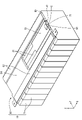
- FIG. FIG. 2 is a perspective view of an electric storage module.
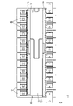
- FIG. 3 is a plan view of the power storage module.
- FIG. 4 is a plan view of the state of FIG. 3 with the outer cover removed.
- FIG. 5 is a plan view of FIG. 4 with the cover removed.
- FIG. 6 is an enlarged view of FIG. 5 showing connection between the flexible substrate and the bus bar and connection between the flexible substrate and the circuit board.
- FIG. 7 is an enlarged view of FIG. 5 showing the periphery of the recess of the protector.
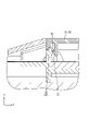
- FIG. 8 is a cross-sectional view of the power storage module taken along line AA of FIG. FIG.
- FIG. 9 is a cross-sectional view of the power storage module taken along the line BB in FIG.
- FIG. 10 is a cross-sectional view of the power storage module taken along line CC of FIG.
- FIG. 11 is an enlarged view of FIG. 4 showing the periphery of the recess of the protector.
- FIG. 12 is a perspective view of the cover.
- FIG. 13 is a perspective view of a busbar.
- 14 is a cross-sectional view of a power storage module showing a water cutoff wall according to a second embodiment;
- FIG. 15 is a cross-sectional view of a power storage module showing a closing portion according to a third embodiment;
- a wiring module according to the present disclosure is a wiring module attached to the upper side of a plurality of power storage elements, and includes a bus bar connected to electrode terminals of the plurality of power storage elements, and a bus bar side connection portion provided on the bus bar.
- a flexible substrate connected to the flexible substrate, a circuit substrate connected to the flexible substrate, and a protector on which the bus bar, the flexible substrate, and the circuit substrate are mounted, wherein It is arranged above the upper surface of the side connection portion.
- the circuit board is connected to the busbar-side connecting portion via the flexible board, and the upper surface of the circuit board is arranged above the upper surface of the busbar-side connecting portion. It is possible to suppress the intrusion of condensed water into the
- the flexible substrate includes a wiring portion, a first connection piece that is superimposed and connected to the upper surface of the busbar side connection portion, and a bridge portion that connects the wiring portion and the first connection piece;
- the protector is provided between a wiring surface on which the wiring portion is placed, a busbar installation portion on which the busbar is installed, and between the wiring surface and the busbar installation portion, and penetrates in the vertical direction. and an opening, and at least a portion of the bridge portion is preferably disposed above or inside the opening.
- the wiring surface is arranged above the upper surface of the busbar side connection portion.
- the bridge portion has a notch portion and is provided so as to be able to expand and contract.
- the provision of the notch makes it easier for the condensed water to drain downward from the bridge through the opening. Further, even if the wiring surface and the upper surface of the busbar side connection portion are displaced in the vertical direction, the bridge portion can extend in the vertical direction, so there is no need to form the bridge portion with extra length.
- the protector has a mounting portion to which the circuit board is mounted, the mounting portion has a partition wall surrounding an outer edge of the circuit board, and a recess provided in the partition wall, and the flexible It is preferable that the board includes a second connection piece extending from the wiring part through the recess toward the circuit board, and the second connection piece is overlapped and connected to the upper surface of the circuit board.
- the circuit board is surrounded by the partition wall except for the recess necessary for connecting the flexible board and the circuit board, so that the intrusion of condensed water from the outside of the mounting portion to the circuit board side is suppressed. can do.
- the recess is provided with a waterproof wall that extends upward from the wiring surface and contacts the lower surface of the second connection piece.
- the waterproof wall can suppress the intrusion of condensed water from the wiring surface and the wiring portion into the circuit board.
- a cover is attached to the mounting portion and covers the circuit board from above.
- the cover is provided with a closing portion configured from an elastic member so as to close the recess, and the lower end of the closing portion is in contact with the upper surface of the second connection piece. is preferred.
- the closed portion can prevent water from entering the circuit board from the wiring portion.
- the cover has a cover main body portion arranged above the mounting portion, and an eaves portion projecting from the cover main body portion to the outside of the mounting portion, and the eaves portion extends from the second It is preferable that the connection piece is covered from above, and that the upper surface of the eaves portion is inclined so as to become lower as the distance from the cover body portion increases outward.
- the circuit board has a circuit board side connection portion connected to the second connection piece, and the lower surface of the second connection piece and the upper surface of the circuit board side connection portion are at the same height. is preferred.
- the wiring module described above is a wiring module for a vehicle that is used by being mounted on the vehicle.
- FIG. 1 Embodiment 1 of the present disclosure will be described with reference to FIGS. 1 to 13.
- FIG. The power storage module 10 including the wiring module 20 of the present embodiment is applied to, for example, the power storage pack 2 mounted on the vehicle 1 as shown in FIG.
- the power storage pack 2 is mounted on a vehicle 1 such as an electric vehicle or a hybrid vehicle and used as a drive source for the vehicle 1 .
- vehicle 1 such as an electric vehicle or a hybrid vehicle
- the reference numerals of other members may be omitted.
- an electricity storage pack 2 is arranged near the center of the vehicle 1 .
- a PCU 3 Power Control Unit
- Electricity storage pack 2 and PCU 3 are connected by wire harness 4 .
- the electricity storage pack 2 and the wire harness 4 are connected by a connector (not shown).
- the electricity storage pack 2 has an electricity storage module 10 having a plurality of electricity storage elements 11 .
- the direction indicated by the arrow Z is upward, the direction indicated by the arrow X is forward, and the direction indicated by the arrow Y is leftward.
- the electricity storage pack 2 includes a plurality of electricity storage modules 10 and a housing (not shown) that accommodates the plurality of electricity storage modules 10 therein. Due to the use of the vehicle 1 or the like, the temperatures of the electric storage element 11 , the bus bar 40 , etc., which will be described later, change abruptly. Due to this temperature difference, dew condensation water is likely to occur inside the housing. In the following, a technique for suppressing infiltration of condensed water adhering to the busbars 40 and condensed water adhering to the ceiling surface of the housing in particular to the circuit board 30 will be described.
- the power storage module 10 includes a plurality of power storage elements 11 arranged in a line and a wiring module 20 attached to the upper surfaces of the plurality of power storage elements 11 .
- the storage element 11 has a flat rectangular parallelepiped shape in which a storage element (not shown) is accommodated. As shown in FIG. 7, the storage element 11 has positive and negative electrode terminals 12A and 12B on its upper surface.
- the wiring module 20 includes two flexible substrates 21A and 21B, a circuit substrate 30 connected to the flexible substrates 21A and 21B, a bus bar 40 connected to the storage element 11, the flexible substrates 21A and 21B. 21B and a protector 50 that holds the bus bar 40. Since the two flexible boards 21A and 21B have the same structure, the configuration of the electrical connection between the flexible board 21A and the flexible board 21A will be described in detail below, and the flexible board 21B will be described. may be omitted.
- the wiring module 20 further includes a cover 70 that covers the circuit board 30 from above (see FIGS. 4 and 5) and an outer cover 80 that covers the area outside the cover 70 from above (see FIGS. 2 to 4). .
- the flexible substrate 21A is a flexible sheet-like substrate. As shown in FIG. 6, the flexible substrate 21A has a base film 22 made of an insulating synthetic resin, and a first conductive path 23 (only a portion of which is shown) wired to the base film 22. As shown in FIG. Although not shown, the base film 22 and the first conductive path 23 are further covered with an insulating layer made of an insulating overlay film, coating film, or the like. As materials for the base film 22 and the insulating layer, polyimide (PI), polyethylene terephthalate (PET), or the like is used, for example.
- the first conductive path 23 is made of metal such as copper or copper alloy, and has electrical conductivity. In this embodiment, the first conductive path 23 is routed on one side of the flexible board 21A, and the flexible board 21A is arranged so that the surface on which the first conductive path 23 is routed faces downward.
- the flexible boards 21A and 21B are arranged between the circuit board 30 and the bus bar 40 in the left-right direction (vertical direction in the figure).
- the flexible substrate 21A includes a wiring portion 24 extending in a strip shape in the front-rear direction (horizontal direction in the drawing), a first connection piece 25 provided on the busbar 40 side, and the wiring portion 24 and the first connection piece 25. and a second connection piece 28 extending from the wiring portion 24 to the circuit board 30 side.
- first connection piece 25 is arranged over the upper surface 43A of the busbar-side connection portion 43 of the busbar 40 .
- a first land 23A is formed on the lower surface of the first connection piece 25 to be arranged at the end of the first conductive path 23 .
- No insulating layer is provided below the first land 23A, and the first land 23A is exposed facing downward.
- the first land 23A is electrically connected to the busbar side connection portion 43 by soldering.
- the bridge portion 26 has a notch portion 27 cut in the front-rear direction and has an elongated shape.
- the bridge portion 26 can be extended and contracted in the front-back direction, the up-down direction, and the left-right direction by the notch portion 27 .
- the bridge portion 26 of this embodiment mainly extends in the vertical direction and connects the wiring portion 24 and the first connection piece 25 .
- the bridge portion 26 can absorb the manufacturing tolerances of the bus bar 40, the flexible substrate 21A, the protector 50, etc., and the assembly tolerances therebetween.
- the second connection pieces 28 are strip-shaped and are arranged in the front-rear direction. The second connection pieces 28 are separated by slits 29 . As shown in FIG. 8 , the second connection piece 28 is arranged over the upper surface 30A of the circuit board 30 . A second land 23B is formed on the lower surface 28A of the second connection piece 28 . As shown in FIG. 6, the second land 23B is arranged at the end of the first conductive path 23 opposite to the first land 23A. No insulating layer is provided below the second land 23B, and the second land 23B is also exposed facing downward like the first land 23A. The second land 23B is electrically connected to the circuit board-side connecting portion 33 of the circuit board 30 by soldering (see FIG. 6).
- the circuit board 30 is a rigid board that does not have flexibility. As shown in FIG. 6, the circuit board 30 includes an insulating plate 31 having insulating properties and a second conductive path 32 (only a portion of which is shown) wired on the insulating plate 31 .
- the insulating plate 31 is formed by, for example, impregnating a glass fiber cloth with an epoxy resin and curing the cloth.
- the second conductive path 32 is made of metal such as copper or copper alloy, and has electrical conductivity.
- the circuit board 30 is arranged so that the surface of the insulating plate 31 on which the second conductive path 32 is arranged faces upward.
- the circuit board 30 has a rectangular shape elongated in the front-rear direction.
- Electronic components E and connectors C are mounted on the circuit board 30 .
- Examples of electronic components E include resistors, capacitors, switching elements, and the like.
- the circuit board 30 is electrically connected by a connector C to an external ECU (Electronic Control Unit) (not shown).
- the ECU is equipped with a microcomputer, elements, etc., and has a well-known configuration with functions for detecting the voltage, current, temperature, etc., of the storage elements 11 and controlling the charging and discharging of each storage element 11. belongs to.
- the circuit board 30 of the present embodiment can be provided with a function of monitoring information such as the voltage and temperature of the storage element 11 and transmitting the information to the ECU.
- the circuit board 30 is provided with a locking recess 34 having a concave shape and a through hole 35 penetrating vertically.
- circuit board side connection part As shown in FIG. 6 , a circuit board side connection portion 33 is provided at the end of the second conductive path 32 .
- the second connection piece 28 is superimposed on the upper surface 33A of the circuit board side connection portion 33, and the circuit board side connection portion 33 is soldered to the second land 23B provided on the second connection piece 28. connected by
- the lower surface 28A of the second connection piece 28 and the upper surface 33A of the circuit board side connection portion 33 are designed to have the same height.
- the lower surface 28A of the second connection piece 28 includes the second land 23B.
- Solder (not shown) is provided in advance on either the second land 23B or the circuit board side connection portion 33, and the second land 23B and the circuit board side connection portion 33 are soldered by reflow. shall have been Since the lower surface 28A of the second connection piece 28 and the upper surface 33A of the circuit board side connection portion 33 are at the same height, the solder that connects the second connection piece 28 and the circuit board side connection portion 33 is not subjected to excessive force. Therefore, the reliability of the electrical connection between the flexible board 21A and the circuit board 30 can be improved.
- the bus bar 40 is a member for connecting the electrode terminals 12A and 12B of the adjacent storage elements 11, and is made of a conductive metal plate. Metals forming the bus bar 40 include copper, copper alloys, aluminum, aluminum alloys, stainless steel (SUS), and the like. As shown in FIG. 13 , the busbar 40 includes a rectangular plate-shaped busbar body 41 , two electrode insertion holes 42 vertically penetrating the busbar body 41 , and an outer ( and a bus bar side connection portion 43 projecting rightward or leftward. As shown in FIG. 6, the electrode terminals 12A and 12B are inserted into the electrode insertion holes 42. As shown in FIG. Bus bar 40 and electrode terminals 12A and 12B are electrically connected by welding.
- the upper surface 43A of the busbar side connection portion 43 is provided below the upper surface of the busbar main body portion 41 .
- the upper surface 43 A of the busbar side connection portion 43 is set lower than the wiring surface 52 of the protector 50 and the upper surface 30 A of the circuit board 30 .
- the upper surface 43A of the busbar side connection portion 43 is connected to the first land 23A provided on the lower surface of the first connection piece 25 by soldering.
- the protector 50 is made of insulating synthetic resin and has a plate shape. As shown in FIG. 5, the protector 50 includes a protector main body 51 in the center in the left-right direction, and wiring surfaces provided on both left and right sides of the protector main body 51 on which the wiring portions 24 of the flexible substrates 21A and 21B are placed. 52, and busbar installation portions 53 provided at the right and left ends of the protector 50 and having the busbars 40 installed thereon. A mounting portion 54 to which the circuit board 30 is mounted is provided in the front half portion of the protector body portion 51 .
- the wiring surface 52 is provided extending in the front-rear direction. Partition walls 55 are provided on both left and right sides of the wiring surface 52 .
- the wiring portions 24 of the flexible substrates 21A and 21B are fixed on the wiring surface 52 by adhesive, adhesive tape, heat crimping, or the like, and partitioned by a partition wall 55.
- the partition wall 55 between the flexible board 21A and the circuit board 30 also serves as a partition wall 58 that constitutes the mounting portion 54.
- the protector 50 has an opening 56 extending vertically between the wiring surface 52 and the busbar installation portion 53 (the rim is partially indicated by broken lines).
- the opening 56 is formed so as to include the bridge portion 26 inside the opening 56 when viewed from above.
- the bridge portion 26 is arranged above or inside the opening 56 . Since the bridge portion 26 has an elongated shape with the cutout portion 27 , condensed water adhering to the bridge portion 26 is easily drained downward (that is, toward the power storage element 11 ) through the opening 56 .
- the wiring surface 52 is arranged above the upper surface 43A of the busbar side connection portion 43, so the wiring portion 24 is arranged above the first connection piece 25. As shown in FIG. This makes it difficult for condensed water to enter the wiring portion 24 from the bus bar 40 via the bridge portion 26 that connects the wiring portion 24 and the first connection piece 25 . Since the bridge portion 26 of the present embodiment has the notch portion 27, the wiring portion 24 and the first connection piece 25 are connected by extending by the vertical displacement between the wiring portion 24 and the first connection piece 25. can do. Therefore, it is not necessary to provide the bridge portion 26 with an extra length corresponding to the vertical displacement between the wiring portion 24 and the first connection piece 25, and the usage of the flexible substrates 21A and 21B can be reduced.
- the mounting portion 54 includes partition walls 58 surrounding the outer edge of the circuit board 30 and recesses 59 provided in the partition walls 58 on both left and right sides of the circuit board 30 .
- the inner upper end 59A of the recess 59 of the present embodiment is provided smoothly and continuously to the wiring surface 52 without steps.
- a second connection piece 28 extending from the wiring portion 24 toward the circuit board 30 is inserted into the recess 59 .
- a bottom surface 57 is a surface of the mounting portion 54 with which the lower surface of the circuit board 30 abuts.
- the front end of the mounting portion 54 is provided with a first connector recess 60 to which the connector C is mounted.
- the bottom surface 57 is provided with a locking piece 61 that extends upward and is flexibly deformable in the left-right direction.
- the locking pieces 61 are arranged so as to lock with the locking recesses 34 of the circuit board 30 .
- the mounting portion 54 is provided with a cylindrical positioning protrusion 62 extending upward.
- the positioning projections 62 are inserted through the through holes 35 of the circuit board 30 to position the circuit board 30 on the mounting portion 54 .
- the partition wall 58 is provided with a locking projection 63 projecting inwardly of the mounting portion 54 .
- the busbar installation portion 53 is formed in a frame shape and is configured so that the busbars 40 can be arranged side by side in the front-rear direction.
- the busbar installation portion 53 has an engaging claw 64 and holds the busbar 40 .
- the busbar installation portion 53 has a busbar concave portion 65 that accommodates the busbar side connection portion 43 .
- the busbar side connection portion 43 accommodated in the busbar recessed portion 65 protrudes outward from the busbar mounting portion 53 and is arranged inside the opening 56 .
- the busbar installation portion 53 has a configuration in which a part of the bottom is missing, and the busbars 40 held by the busbar installation portion 53 are electrically connected to the plurality of storage elements 11 . be.
- the cover 70 is made of insulating synthetic resin and is a lid-like member. As shown in FIG. 12, the cover 70 has a cover main body portion 71 that has a rectangular shape when viewed from above, and an eaves portion 72 that protrudes from the cover main body portion 71 in the left-right direction. As shown in FIG. 8, the cover 70 is attached to the mounting portion 54 and configured to cover the circuit board 30 from above. The eaves portion 72 is arranged to protrude outside the mounting portion 54 .
- the eaves portion 72 is configured to cover the concave portion 59 and the second connecting piece 28 from above. Therefore, when the condensed water adhering to the ceiling surface of the housing falls onto the cover 70 from above, it is possible to prevent the condensed water from entering the circuit board 30 .
- an upper surface 72A of the eaves portion 72 is inclined so as to become lower as it goes away from the cover body portion 71 to the outside (left side in the drawing). As a result, the condensed water falling from above the cover 70 can be drained downward toward the wiring portion 24, the wiring surface 52, and the like. Further, since a part of the edge 72B of the eaves portion 72 is arranged above the edge of the opening 56, the condensation water on the upper surface 72A of the eaves portion 72 can be drained through the opening 56 toward the power storage element 11 side. is also possible.
- the cover 70 has a cover-side partition wall 78 extending downward and arranged inside the recess 59 .
- a lower end portion of the cover-side partition wall 78 is arranged so as not to contact the upper surface 28B of the second connection piece 28 .
- the cover-side partition wall 78 is provided so as to be continuous with the partition wall 58 of the mounting portion 54 in the front-rear direction (perpendicular to the plane of the drawing). That is, since the cover-side partition wall 78 is configured to partially close the recessed portion 59 in the left-right direction, it is possible to prevent condensed water from entering the mounting portion 54 .
- a second connector concave portion 73 is provided at the front end portion of the cover main body portion 71 .
- the second connector recess 73 is attached to the upper portion of the connector C attached to the first connector recess 60, and the connector C is surrounded by the first connector recess 60 and the second connector recess 73 without any gap. It is designed to be
- a locking portion 74 that locks with the locking projection 63 is provided on the lower side of the cover main body portion 71 . Thereby, the cover 70 is locked to the mounting portion 54 .
- an engaging projection 75 is provided on the lower side of the cover body portion 71 and arranged between the partition wall 58 and the locking piece 61 . The engaging protrusion 75 positions the cover 70 with respect to the mounting portion 54 , and the locking piece 61 bends toward the partition wall 58 to release the locking between the locking piece 61 and the locking recess 34 of the circuit board 30 . It is restrained.
- stepped portions 76 recessed downward from the upper surface 71A of the cover body portion 71 are provided on the right and left portions of the rear half portion of the cover body portion 71 .
- the stepped portion 76 is provided so as to spread forward and rearward from the eaves portion 72 .
- the stepped portion 76 and the upper surface 71A of the cover body portion 71 are connected by a groove portion 77 .
- the groove portion 77 is recessed further downward than the stepped portion 76 .
- the outer cover 80 is made of insulating synthetic resin and is a lid-shaped member. As shown in FIGS. 2 and 3, the outer cover 80 is a member for covering a part of the cover 70 and the outer part of the wiring module 20 not covered by the cover 70 from above. That is, as shown in FIG. 8, the outer cover 80 covers the wiring portion 24 outside the mounting portion 54, the bus bar 40, and the like from above. Although detailed description is omitted, the outer cover 80 (outer wall portion 82) and the outer edge portion (busbar installation portion 53) of the protector 50 have engagement portions similar to the locking portions 74 and locking projections 63 shown in FIG. A stop structure is provided for each, and the outer cover 80 is attached to the protector 50 .
- the outer cover 80 has an inner wall portion 81 that overlaps the upper surface of the stepped portion 76 of the cover 70, and an outer wall portion 82 that covers the busbar 40 and the busbar installation portion 53 from above. ing.
- a first inclined portion 83 , an intermediate wall portion 84 and a second inclined portion 85 are provided between the inner wall portion 81 and the outer wall portion 82 .
- the intermediate wall portion 84 is provided below the inner wall portion 81 and the outer wall portion 82 .
- the intermediate wall portion 84 is connected to the inner wall portion 81 via the first inclined portion 83 and is connected to the outer wall portion 82 via the second inclined portion 85 .
- the inner end portion of the inner wall portion 81 is provided with an engagement convex portion 86 protruding downward.
- the engagement protrusion 86 engages with the groove 77 of the cover 70 to position the outer cover 80 with respect to the cover 70 .
- the engaging projection 86 and the groove 77 are engaged with each other with a clearance so that after a certain amount of condensed water accumulates in the groove 77, the condensed water enters the inner side of the outer cover 80. It's becoming In this way, the vicinity of the recessed portion 59 of the protector 50 is double covered from above by the outer cover 80 and the cover 70 , so that the condensed water falling from above is less likely to enter the circuit board 30 .
- a projecting wall 87 extending downward is provided on the side of the outer wall portion 82 of the second inclined portion 85 .
- the projecting wall 87 is provided in the vicinity of the busbar installation portion 53 , and the dew condensation water adhering to the busbar 40 and the busbar installation portion 53 is guided downward by the projecting wall 87 and drained downward through the opening 56 . It has become so.
- the first inclined portion 83 is formed with a clearance from the upper surface 72A of the eaves portion 72 . As a result, when condensed water enters between the outer cover 80 and the cover 70 , the condensed water is easily drained by the eaves portion 72 .
- condensed water is collected along the first inclined portion 83 and the second inclined portion 85 on the intermediate wall portion 84 provided lower than the surrounding wall portions.
- Condensed water adhering to the inner side of the outer cover 80 is collected on the lower surface of the intermediate wall portion 84 and is easily drained to the opening 56 below the intermediate wall portion 84, the wiring portion 24, and the like.
- condensed water tends to accumulate on the upper surface of the intermediate wall portion 84 , and does not easily accumulate on the upper surface of the inner wall portion 81 . It becomes difficult to penetrate to the circuit board 30 through.
- the upper surface of the intermediate wall portion 84 has a region (for example, the latter half of the outer cover 80) where the condensed water can escape sufficiently even if the condensed water adheres. not.
- a wiring module 20 according to the first embodiment is a wiring module 20 attached to the upper side of a plurality of storage elements 11, and includes a bus bar 40 connected to electrode terminals 12A and 12B of the plurality of storage elements 11, and a bus bar 40 provided on the bus bar 40.
- the flexible boards 21A and 21B connected to the busbar side connection portions 43, the circuit board 30 connected to the flexible boards 21A and 21B, the busbar 40, the flexible boards 21A and 21B, and the circuit board 30 are placed.
- a protector 50 is provided, and the upper surface 30A of the circuit board 30 is arranged above the upper surface 43A of the busbar side connection portion 43 .
- the circuit board 30 is connected to the busbar side connection portion 43 via the flexible boards 21A and 21B, and the upper surface 30A of the circuit board 30 is arranged above the upper surface 43A of the busbar side connection portion 43. As a result, entry of condensed water from the bus bar 40 into the circuit board 30 can be suppressed.
- the flexible substrates 21A and 21B include the wiring portion 24, the first connection piece 25 that is overlaid and connected to the upper surface 43A of the busbar side connection portion 43, and the wiring portion 24 and the first connection piece 25.
- the protector 50 includes a connecting bridge portion 26 , a wiring surface 52 on which the wiring portion 24 is placed, a busbar installation portion 53 on which the busbars 40 are installed, and the wiring surface 52 and the busbar installation portion 53 . and an opening 56 that is provided therebetween and penetrates in the vertical direction, and at least a portion of the bridge portion 26 is arranged above or inside the opening 56 .
- the wiring surface 52 is arranged above the upper surface 43A of the busbar-side connection portion 43 .
- the condensation water does not enter the wiring portions 24 from the busbar 40 through the bridge portion 26. can be suppressed.
- the bridge part 26 has the notch part 27 and is provided so as to be able to expand and contract.
- provision of the notch portion 27 makes it easier for the condensed water to drain downward from the bridge portion 26 through the opening 56 . Further, even if the wiring surface 52 and the upper surface 43A of the busbar side connection portion 43 are displaced in the vertical direction, the bridge portion 26 can extend in the vertical direction. There is no
- the protector 50 has a mounting portion 54 to which the circuit board 30 is mounted, and the mounting portion 54 includes a partition wall 58 surrounding the outer edge of the circuit board 30 and a concave portion 59 provided in the partition wall 58.
- the flexible boards 21A and 21B have a second connection piece 28 extending from the wiring portion 24 through the recess 59 toward the circuit board 30, the second connection piece 28 being superimposed on the upper surface 30A of the circuit board 30, It is connected.
- the circuit board 30 is surrounded by the partition walls 58 except for the recesses 59 necessary for connecting the flexible boards 21A, 21B and the circuit board 30. Intrusion of condensed water to the side can be suppressed.
- a cover 70 is provided which is attached to the mounting portion 54 and covers the circuit board 30 from above.
- the cover 70 has a cover main body portion 71 arranged above the mounting portion 54, and an eaves portion 72 projecting from the cover main body portion 71 to the outside of the mounting portion 54.
- the eaves portion 72 is , and covers the second connection piece 28 from above, and the upper surface 72A of the eaves portion 72 is inclined so as to become lower as it goes away from the cover body portion 71 to the outside.
- the circuit board 30 includes the circuit board side connection portion 33 connected to the second connection piece 28, and the bottom surface 28A of the second connection piece 28 and the top surface 33A of the circuit board side connection portion 33 are the same. It is said to be high.
- connection reliability between the flexible boards 21A, 21B and the circuit board 30 can be improved.
- Embodiment 2 of the present disclosure will be described with reference to FIG. 14 .
- the wiring module 120 according to the second embodiment is configured in the same manner as in the first embodiment except that the protector 150 has a water stop wall 151. Therefore, the same members and effects as those in the first embodiment will not be described. is omitted.
- a plurality of identical members only some members may be given reference numerals, and the reference numerals of other members may be omitted.
- a waterproof wall 151 extending upward from the wiring surface 52 is provided inside the recess 159 of the protector 150 . Therefore, the water stop wall 151 makes it difficult for condensed water to enter the circuit board 30 from the wiring surface 52 . Also, the upper end portion 151A of the water cutoff wall 151 contacts the lower surface 28A of the second connection piece 28 that is passed through the recess 159 . Therefore, the wiring portion 24 is inclined downward from the circuit board 30 side toward the opening 56 , and it is possible to suppress the entry of condensed water from the wiring portion 24 into the circuit board 30 .
- the recess 159 is provided with a water cutoff wall 151 that extends upward from the wiring surface 52 and contacts the lower surface 28A of the second connection piece 28 .
- the water stop wall 151 can suppress the entry of condensed water from the wiring surface 52 and the wiring portion 24 into the circuit board 30 .
- Embodiment 3 of the present disclosure will be described with reference to FIG. 15 .
- the wiring module 220 according to the third embodiment is configured in the same manner as in the first embodiment except that the cover 270 has a closing portion 271. Therefore, the same members and effects as in the first embodiment will not be described. omitted.
- a plurality of identical members only some members may be given reference numerals, and the reference numerals of other members may be omitted.
- the cover-side partition wall 78 of the cover 270 is attached with a closing portion 271 made of an elastic member such as sponge or rubber. Since the closing portion 271 is made of an elastic member, the lower end portion 271A of the closing portion 271 can be provided so as to contact the upper surface 28B of the second connecting piece 28 . As a result, the closing portion 271 can block the entire recessed portion 59 in the left-right direction, thereby suppressing intrusion of condensed water from the wiring portion 24 into the circuit board 30 . Further, when the closing portion 271 is made of a sponge, it is possible to prevent the condensed water from entering the circuit board 30 by absorbing the condensed water with the sponge.
- an elastic member such as sponge or rubber
- the cover 270 is provided with a closing portion 271 that is arranged to close the recess 59 and is made of an elastic member. in contact.
- the closing portion 271 can prevent water from entering the circuit board 30 from the wiring portion 24 .
- a rigid board is used as the circuit board 30, but the circuit board is not limited to this, and the circuit board may be a flexible board.
- the bus bar 40 and the flexible substrates 21A and 21B are directly connected, but the present invention is not limited to this. It may be configured to be connected by (3)
- the outer cover 80 is provided outside the cover 70. However, the present invention is not limited to this, and a configuration without the outer cover may be employed.
Landscapes
- Chemical & Material Sciences (AREA)
- Chemical Kinetics & Catalysis (AREA)
- Electrochemistry (AREA)
- General Chemical & Material Sciences (AREA)
- Engineering & Computer Science (AREA)
- Mechanical Engineering (AREA)
- Battery Mounting, Suspending (AREA)
- Connection Of Batteries Or Terminals (AREA)
- Structure Of Printed Boards (AREA)
- Combinations Of Printed Boards (AREA)
Abstract
Description
最初に本開示の実施態様を列挙して説明する。
以下に、本開示の実施形態について説明する。本開示はこれらの例示に限定されるものではなく、特許請求の範囲によって示され、特許請求の範囲と均等の意味および範囲内での全ての変更が含まれることが意図される。
本開示の実施形態1について、図1から図13を参照しつつ説明する。本実施形態の配線モジュール20を備えた蓄電モジュール10は、例えば、図1に示すように、車両1に搭載される蓄電パック2に適用される。蓄電パック2は、電気自動車またはハイブリッド自動車等の車両1に搭載されて、車両1の駆動源として用いられる。以下の説明においては、複数の同一部材については、一部の部材にのみ符号を付し、他の部材の符号を省略する場合がある。
蓄電パック2は、複数の蓄電モジュール10と、複数の蓄電モジュール10を内部に収容する筐体(図示せず)と、を備えて構成されている。車両1の使用等により、後述する蓄電素子11やバスバー40等の温度は急激に変化するため、蓄電パック2の筐体の内部と外部との間で温度差が生じる。この温度差によって、筐体の内部には、結露水が発生しやすくなっている。以下では、特に、バスバー40に付着した結露水、及び筐体の天井面に付着した結露水が、回路基板30へと浸入することを抑制するための技術について説明する。
図5に示すように、配線モジュール20は、2つのフレキシブル基板21A,21Bと、フレキシブル基板21A,21Bに接続される回路基板30と、蓄電素子11に接続されるバスバー40と、フレキシブル基板21A,21Bおよびバスバー40を保持するプロテクタ50と、を備える。2つのフレキシブル基板21A,21Bは同様の構造を有するため、以下には、一方のフレキシブル基板21A、およびフレキシブル基板21Aの電気的接続にかかる構成について詳細に説明し、他方のフレキシブル基板21Bについては説明を省略する場合がある。
フレキシブル基板21Aは、可撓性を有するシート状の基板である。図6に示すように、フレキシブル基板21Aは、絶縁性の合成樹脂からなるベースフィルム22と、ベースフィルム22に配索される第1導電路23(一部のみ図示)と、を有する。図示しないが、ベースフィルム22および第1導電路23は、さらに絶縁性のオーバーレイフィルムや塗膜等からなる絶縁層により覆われている。ベースフィルム22や絶縁層の材料としては、例えばポリイミド(PI)やポリエチレンテレフタレート(PET)等が用いられる。第1導電路23は、例えば銅または銅合金などの金属からなり、導電性を有している。本実施形態では、第1導電路23は、フレキシブル基板21Aの片面に配索されており、フレキシブル基板21Aは、第1導電路23の配索された面が下方を向くように配置される。
図5に示すように、フレキシブル基板21A,21Bは、左右方向(図示上下方向)において、回路基板30とバスバー40との間に配されている。図6に示すように、フレキシブル基板21Aは、前後方向(図示左右方向)に帯状にのびる配線部24と、バスバー40側に設けられる第1接続片25と、配線部24と第1接続片25とを連結するブリッジ部26と、配線部24から回路基板30側にのびて設けられる第2接続片28と、を備えている。
図8に示すように、第1接続片25は、バスバー40のバスバー側接続部43の上面43Aに重ねて配されている。図6に示すように、第1接続片25の下面には、第1導電路23の端部に配される第1ランド23Aが形成されている。第1ランド23Aの下方には、絶縁層が設けられておらず、第1ランド23Aは下方を向いて露出して設けられている。第1ランド23Aは、バスバー側接続部43と半田付けにより電気的に接続される。
図6に示すように、ブリッジ部26は、前後方向に切り欠かれた切り欠き部27を有し、細長い形状をなしている。ブリッジ部26は、切り欠き部27により、前後方向、上下方向、及び左右方向に伸縮可能とされている。図8に示すように、本実施形態のブリッジ部26は、主として上下方向に伸びて、配線部24と第1接続片25とを連結している。また、ブリッジ部26により、バスバー40やフレキシブル基板21A、プロテクタ50等の製造公差、及びこれらの間の組み付け公差を吸収することもできる。
図6に示すように、第2接続片28は、短冊状をなし、前後方向に並んでいる。第2接続片28同士は、スリット29により分割されている。図8に示すように、第2接続片28は、回路基板30の上面30Aに重ねて配されている。第2接続片28の下面28Aには、第2ランド23Bが形成されている。図6に示すように、第2ランド23Bは、第1導電路23における第1ランド23Aと反対側の端部に配されている。第2ランド23Bの下方には、絶縁層が設けられておらず、第2ランド23Bも第1ランド23Aと同様に、下方を向いて露出している。第2ランド23Bは、回路基板30の回路基板側接続部33と半田付けにより電気的に接続される(図6参照)。
本実施形態にかかる回路基板30は、可撓性を有しないリジッド基板とされている。図6に示すように、回路基板30は、絶縁性を有する絶縁板31と、この絶縁板31に配索された第2導電路32(一部のみ図示)と、を備える。絶縁板31は、例えばガラス繊維布にエポキシ樹脂を含浸させて硬化させることにより形成される。第2導電路32は、例えば銅または銅合金などの金属からなり、導電性を有している。回路基板30は、絶縁板31の第2導電路32が配索された面が上側となるように配置される。
図6に示すように、第2導電路32の端部には、回路基板側接続部33が設けられている。回路基板側接続部33の上面33Aには、第2接続片28が重ねられるようになっており、回路基板側接続部33は、第2接続片28に設けられた第2ランド23Bと半田付けにより接続される。
図6に示すように、バスバー40は、隣り合う蓄電素子11の電極端子12A,12Bを接続するための部材であって、導電性を有する金属板材からなる。バスバー40を構成する金属としては、銅、銅合金、アルミニウム、アルミニウム合金、ステンレス鋼(SUS)等が挙げられる。図13に示すように、バスバー40は、長方形の板状をなすバスバー本体部41と、バスバー本体部41に上下方向に貫通形成された2つの電極挿通孔42と、バスバー本体部41から外側(右側または左側)に突出するバスバー側接続部43と、を有している。図6に示すように、電極挿通孔42には、電極端子12A,12Bが挿通されるようになっている。バスバー40と電極端子12A,12Bとは溶接により電気的に接続される。
図13に示すように、バスバー側接続部43の上面43Aは、バスバー本体部41の上面よりも下方に設けられている。図8に示すように、配線モジュール20においては、バスバー側接続部43の上面43Aは、プロテクタ50の配線面52、回路基板30の上面30Aよりも下方となるように設定されている。バスバー側接続部43の上面43Aは、第1接続片25の下面に設けられた第1ランド23Aと半田付けにより接続されている。
プロテクタ50は、絶縁性の合成樹脂からなり、板状をなしている。図5に示すように、プロテクタ50は、左右方向の中央部のプロテクタ本体部51と、プロテクタ本体部51の左右両側に設けられ、フレキシブル基板21A,21Bの配線部24が載置される配線面52と、プロテクタ50の右端部および左端部に設けられ、バスバー40が配設されるバスバー配設部53と、を備える。プロテクタ本体部51の前半部分には、回路基板30が装着される装着部54が設けられている。
図5に示すように、配線面52は、前後方向にのびて設けられている。配線面52の左右両側には、仕切り壁55が設けられている。フレキシブル基板21A,21Bの配線部24は、接着剤、粘着テープ、熱かしめ等により、配線面52上に固定され、仕切り壁55によって仕切られるようになっている。なお、図7に示すように、フレキシブル基板21Aと回路基板30との間の仕切り壁55は、装着部54を構成する隔壁58を兼ねている。
図7に示すように、プロテクタ50は、配線面52とバスバー配設部53との間に、上下方向に貫通する開口56を有している(口縁を一部破線で示す)。開口56は、上方から見た場合にブリッジ部26を開口56の内部に含むように形成されている。前方からの断面図では、図8に示すように、ブリッジ部26は開口56の上方あるいは内部に配されるようになっている。ブリッジ部26は、切り欠き部27を有する細長い形状をなしているため、ブリッジ部26に付着した結露水は開口56を通じて下方(すなわち蓄電素子11側)に排水されやすくなっている。
図7に示すように、装着部54は、回路基板30の外縁部を囲む隔壁58と、回路基板30の左右両側の隔壁58に設けられる凹部59と、を備えている。図8に示すように、本実施形態の凹部59の内側の上端59Aは、段差なく滑らかに配線面52に連続して設けられている。凹部59には、配線部24から回路基板30側へのびる第2接続片28が挿通されるようになっている。装着部54において、回路基板30の下面が当接する面は、底面57とされている。図5に示すように、装着部54の前端部には、コネクタCが装着される第1コネクタ凹部60が設けられている。
カバー70は、絶縁性の合成樹脂製であって、蓋状の部材とされている。図12に示すように、カバー70は、上方から見た場合に方形状をなすカバー本体部71と、カバー本体部71から左右方向に突出して設けられるひさし部72と、を有している。図8に示すように、カバー70は、装着部54に取り付けられ、回路基板30を上方から覆うように構成されている。ひさし部72は、装着部54の外側に突出して配されるようになっている。
実施形態1によれば、以下の作用、効果を奏する。
実施形態1にかかる配線モジュール20は、複数の蓄電素子11の上側に取り付けられる配線モジュール20であって、複数の蓄電素子11の電極端子12A,12Bに接続されるバスバー40と、バスバー40に設けられたバスバー側接続部43と接続されるフレキシブル基板21A,21Bと、フレキシブル基板21A,21Bと接続される回路基板30と、バスバー40とフレキシブル基板21A,21Bと回路基板30とが載置されるプロテクタ50と、を備え、回路基板30の上面30Aは、バスバー側接続部43の上面43Aよりも上方に配されている。
本開示の実施形態2について、図14を参照しつつ説明する。実施形態2にかかる配線モジュール120は、プロテクタ150が止水壁151を有する点を除いて、実施形態1と同様に構成されているため、実施形態1と同一の部材、作用効果については、説明を省略する。なお、複数の同一部材については、一部の部材にのみ符号を付し、他の部材の符号を省略する場合がある。
実施形態2によれば、以下の作用、効果を奏する。
実施形態2では、凹部159には、配線面52から上方にのび、第2接続片28の下面28Aに接触する止水壁151が設けられている。
本開示の実施形態3について、図15を参照しつつ説明する。実施形態3にかかる配線モジュール220は、カバー270が閉鎖部271を有する点を除いて、実施形態1と同様に構成されているため、実施形態1と同一の部材、作用効果については、説明を省略する。なお、複数の同一部材については、一部の部材にのみ符号を付し、他の部材の符号を省略する場合がある。
実施形態3によれば、以下の作用、効果を奏する。
実施形態3では、カバー270には、凹部59を塞ぐように配され、弾性部材から構成される閉鎖部271が設けられ、閉鎖部271の下端部271Aは、第2接続片28の上面28Bに接触している。
(1)上記実施形態では、回路基板30としてリジッド基板を用いたが、これに限られることはなく、回路基板はフレキシブル基板であってもよい。
(2)上記実施形態では、バスバー40とフレキシブル基板21A,21Bとは、直接接続される構成としたが、これに限られることはなく、バスバーとフレキシブル基板とは、ニッケル等の金属小片を介して接続される構成としてもよい。
(3)上記実施形態では、カバー70の外側にアウターカバー80が設けられる構成としたが、これに限られることはなく、アウターカバーを備えない構成としてもよい。
2: 蓄電パック
3: PCU
4: ワイヤーハーネス
10: 蓄電モジュール
11: 蓄電素子
12A,12B: 電極端子
20,120,220: 配線モジュール
21A,21B: フレキシブル基板
22: ベースフィルム
23: 第1導電路
23A: 第1ランド
23B: 第2ランド
24: 配線部
25: 第1接続片
26: ブリッジ部
27: 切り欠き部
28: 第2接続片
28A: 第2接続片の下面
28B: 第2接続片の上面
29: スリット
30: 回路基板
30A: 回路基板の上面
31: 絶縁板
32: 第2導電路
33: 回路基板側接続部
33A: 回路基板側接続部の上面
34: 係止凹部
35: 貫通孔
40: バスバー
41: バスバー本体部
42: 電極挿通孔
43: バスバー側接続部
43A: バスバー側接続部の上面
50,150: プロテクタ
51: プロテクタ本体部
52: 配線面
53: バスバー配設部
54: 装着部
55: 仕切り壁
56: 開口
57: 底面
58: 隔壁
59,159: 凹部
59A: 凹部の内側の上端
60: 第1コネクタ凹部
61: 係止片
62: 位置決め凸部
63: 係止突起
64: 係止爪
65: バスバー凹部
70,270: カバー
71: カバー本体部
71A: カバー本体部の上面
72: ひさし部
72A: ひさし部の上面
72B: ひさし部の端縁
73: 第2コネクタ凹部
74: 係止部
75: 係合突起
76: 段差部
77: 溝部
78: カバー側隔壁
80: アウターカバー
81: 内側壁部
82: 外側壁部
83: 第1傾斜部
84: 中間壁部
85: 第2傾斜部
86: 係合凸部
87: 突壁
151: 止水壁
151A: 止水壁の上端部
271: 閉鎖部
271A: 閉鎖部の下端部
C: コネクタ
E: 電子部品
Claims (11)
- 複数の蓄電素子の上側に取り付けられる配線モジュールであって、
前記複数の蓄電素子の電極端子に接続されるバスバーと、
前記バスバーに設けられたバスバー側接続部と接続されるフレキシブル基板と、
前記フレキシブル基板と接続される回路基板と、
前記バスバーと前記フレキシブル基板と前記回路基板とが載置されるプロテクタと、を備え、
前記回路基板の上面は、前記バスバー側接続部の上面よりも上方に配されている、配線モジュール。 - 前記フレキシブル基板は、配線部と、前記バスバー側接続部の上面に重ねられ、接続される第1接続片と、前記配線部と前記第1接続片とを連結するブリッジ部を備え、
前記プロテクタは、前記配線部が載置される配線面と、前記バスバーが配設されるバスバー配設部と、前記配線面と前記バスバー配設部との間に設けられ、上下方向に貫通する開口と、を有し、
前記開口の上方または内部には、前記ブリッジ部の少なくとも一部が配されている、請求項1に記載の配線モジュール。 - 前記配線面は、前記バスバー側接続部の上面よりも上方に配されている、請求項2に記載の配線モジュール。
- 前記ブリッジ部は、切り欠き部を有し、伸縮可能に設けられている、請求項3に記載の配線モジュール。
- 前記プロテクタは、前記回路基板が装着される装着部を有し、
前記装着部は、前記回路基板の外縁部を囲む隔壁と、前記隔壁に設けられる凹部と、を有し、
前記フレキシブル基板は、前記配線部から前記凹部を通って前記回路基板側にのびる第2接続片を備え、
前記第2接続片は、前記回路基板の上面に重ねられ、接続されている、請求項2から請求項4のいずれか一項に記載の配線モジュール。 - 前記凹部には、前記配線面から上方にのび、前記第2接続片の下面に接触する止水壁が設けられている、請求項5に記載の配線モジュール。
- 前記装着部に取り付けられ、前記回路基板を上方から覆うカバーが設けられている、請求項5または請求項6に記載の配線モジュール。
- 前記カバーには、前記凹部を塞ぐように配され、弾性部材から構成される閉鎖部が設けられ、
前記閉鎖部の下端部は、前記第2接続片の上面に接触している、請求項7に記載の配線モジュール。 - 前記カバーは、前記装着部の上方に配されるカバー本体部と、前記カバー本体部から前記装着部の外側に突出するひさし部と、を有し、
前記ひさし部は、前記第2接続片を上方から覆っており、
前記ひさし部の上面は、前記カバー本体部から外側に遠ざかるにつれて低くなるように傾斜している、請求項7または請求項8に記載の配線モジュール。 - 前記回路基板は、前記第2接続片と接続される回路基板側接続部を備え、
前記第2接続片の下面と前記回路基板側接続部の上面は、同一の高さとされている、請求項5から請求項9のいずれか一項に記載の配線モジュール。 - 車両に搭載されて用いられる車両用の配線モジュールであって、請求項1から請求項10のいずれか一項に記載の配線モジュール。
Priority Applications (2)
| Application Number | Priority Date | Filing Date | Title |
|---|---|---|---|
| CN202280008730.9A CN116670913A (zh) | 2021-01-19 | 2022-01-06 | 配线模块 |
| US18/270,582 US20240063497A1 (en) | 2021-01-19 | 2022-01-06 | Wiring module |
Applications Claiming Priority (2)
| Application Number | Priority Date | Filing Date | Title |
|---|---|---|---|
| JP2021-006350 | 2021-01-19 | ||
| JP2021006350A JP7524772B2 (ja) | 2021-01-19 | 2021-01-19 | 配線モジュール |
Publications (1)
| Publication Number | Publication Date |
|---|---|
| WO2022158293A1 true WO2022158293A1 (ja) | 2022-07-28 |
Family
ID=82548805
Family Applications (1)
| Application Number | Title | Priority Date | Filing Date |
|---|---|---|---|
| PCT/JP2022/000173 Ceased WO2022158293A1 (ja) | 2021-01-19 | 2022-01-06 | 配線モジュール |
Country Status (4)
| Country | Link |
|---|---|
| US (1) | US20240063497A1 (ja) |
| JP (2) | JP7524772B2 (ja) |
| CN (1) | CN116670913A (ja) |
| WO (1) | WO2022158293A1 (ja) |
Families Citing this family (1)
| Publication number | Priority date | Publication date | Assignee | Title |
|---|---|---|---|---|
| EP4152485A4 (en) * | 2021-07-30 | 2023-05-31 | Contemporary Amperex Technology Co., Limited | BATTERY CASE, BATTERY, POWER APPLICATION DEVICE AND METHOD AND APPARATUS FOR MAKING A BATTERY |
Citations (2)
| Publication number | Priority date | Publication date | Assignee | Title |
|---|---|---|---|---|
| WO2015107583A1 (ja) * | 2014-01-17 | 2015-07-23 | 三洋電機株式会社 | 電源装置 |
| WO2015159524A1 (ja) * | 2014-04-17 | 2015-10-22 | パナソニックIpマネジメント株式会社 | バスバーモジュール、バッテリ監視モジュールおよびバッテリモジュール |
Family Cites Families (8)
| Publication number | Priority date | Publication date | Assignee | Title |
|---|---|---|---|---|
| JP5702947B2 (ja) | 2010-04-22 | 2015-04-15 | 矢崎総業株式会社 | 配線材 |
| US9905832B2 (en) * | 2012-09-03 | 2018-02-27 | Autonetworks Technologies, Ltd. | Battery wiring module |
| JP6164489B2 (ja) | 2014-01-21 | 2017-07-19 | 株式会社オートネットワーク技術研究所 | 配線モジュール |
| CN109301634B (zh) | 2017-07-24 | 2020-06-19 | 莫仕连接器(成都)有限公司 | 电池连接模块 |
| JP6691178B2 (ja) | 2018-07-10 | 2020-04-28 | 矢崎総業株式会社 | プロテクタ、及び、バスバモジュール |
| JP7385807B2 (ja) | 2018-10-02 | 2023-11-24 | 株式会社オートネットワーク技術研究所 | フレキシブルプリント基板、及び配線モジュール |
| JP7029645B2 (ja) * | 2018-10-02 | 2022-03-04 | 株式会社オートネットワーク技術研究所 | フレキシブルプリント基板、配線部材、蓄電モジュールおよび接続モジュール |
| JP7253525B2 (ja) | 2020-12-21 | 2023-04-06 | プライムプラネットエナジー&ソリューションズ株式会社 | 蓄電モジュール |
-
2021
- 2021-01-19 JP JP2021006350A patent/JP7524772B2/ja active Active
-
2022
- 2022-01-06 US US18/270,582 patent/US20240063497A1/en active Pending
- 2022-01-06 CN CN202280008730.9A patent/CN116670913A/zh active Pending
- 2022-01-06 WO PCT/JP2022/000173 patent/WO2022158293A1/ja not_active Ceased
-
2023
- 2023-02-24 JP JP2023026956A patent/JP7517494B2/ja active Active
Patent Citations (2)
| Publication number | Priority date | Publication date | Assignee | Title |
|---|---|---|---|---|
| WO2015107583A1 (ja) * | 2014-01-17 | 2015-07-23 | 三洋電機株式会社 | 電源装置 |
| WO2015159524A1 (ja) * | 2014-04-17 | 2015-10-22 | パナソニックIpマネジメント株式会社 | バスバーモジュール、バッテリ監視モジュールおよびバッテリモジュール |
Also Published As
| Publication number | Publication date |
|---|---|
| US20240063497A1 (en) | 2024-02-22 |
| JP2023071799A (ja) | 2023-05-23 |
| JP2022110745A (ja) | 2022-07-29 |
| CN116670913A (zh) | 2023-08-29 |
| JP7517494B2 (ja) | 2024-07-17 |
| JP7524772B2 (ja) | 2024-07-30 |
Similar Documents
| Publication | Publication Date | Title |
|---|---|---|
| JP7598541B2 (ja) | 配線モジュール | |
| JP6790923B2 (ja) | 接続モジュール | |
| US20240014501A1 (en) | Wiring module | |
| US7841869B2 (en) | Connector for board and electrical junction box | |
| US9853331B2 (en) | Cover for batteries | |
| JP7569500B2 (ja) | 配線モジュール及びバスバーユニット | |
| US12144107B2 (en) | Substrate connection structure and vehicle wiring module | |
| JP7517494B2 (ja) | フレキシブル基板及び配線モジュール | |
| US20240006724A1 (en) | Bus bar module | |
| US10582632B2 (en) | Board unit | |
| US20250202082A1 (en) | Wiring module | |
| US20250364697A1 (en) | Wiring module | |
| US12237598B2 (en) | In-vehicle wiring module | |
| JP7560509B2 (ja) | バスバモジュール | |
| JP7839470B2 (ja) | 配線モジュール | |
| JP7684270B2 (ja) | バスバモジュール | |
| US20260113890A1 (en) | Electrical connection unit | |
| JP7684269B2 (ja) | バスバモジュール | |
| CN115621636B (zh) | 蓄电装置 | |
| US20260058322A1 (en) | Bus bar module case and bus bar module | |
| US20260128559A1 (en) | Electrical connection unit | |
| CN121602129A (zh) | 线束和汇流条模块 | |
| WO2024116884A1 (ja) | バスバモジュール | |
| WO2022163420A1 (ja) | 配線モジュール |
Legal Events
| Date | Code | Title | Description |
|---|---|---|---|
| 121 | Ep: the epo has been informed by wipo that ep was designated in this application |
Ref document number: 22742418 Country of ref document: EP Kind code of ref document: A1 |
|
| WWE | Wipo information: entry into national phase |
Ref document number: 202280008730.9 Country of ref document: CN |
|
| WWE | Wipo information: entry into national phase |
Ref document number: 18270582 Country of ref document: US |
|
| NENP | Non-entry into the national phase |
Ref country code: DE |
|
| 122 | Ep: pct application non-entry in european phase |
Ref document number: 22742418 Country of ref document: EP Kind code of ref document: A1 |