WO2022158015A1 - 産業用無線通信システム - Google Patents
産業用無線通信システム Download PDFInfo
- Publication number
- WO2022158015A1 WO2022158015A1 PCT/JP2021/030506 JP2021030506W WO2022158015A1 WO 2022158015 A1 WO2022158015 A1 WO 2022158015A1 JP 2021030506 W JP2021030506 W JP 2021030506W WO 2022158015 A1 WO2022158015 A1 WO 2022158015A1
- Authority
- WO
- WIPO (PCT)
- Prior art keywords
- synchronous connection
- communication system
- remote
- wireless communication
- synchronous
- Prior art date
- Legal status (The legal status is an assumption and is not a legal conclusion. Google has not performed a legal analysis and makes no representation as to the accuracy of the status listed.)
- Ceased
Links
Images


Classifications
-
- H—ELECTRICITY
- H04—ELECTRIC COMMUNICATION TECHNIQUE
- H04W—WIRELESS COMMUNICATION NETWORKS
- H04W56/00—Synchronisation arrangements
- H04W56/001—Synchronization between nodes
-
- H—ELECTRICITY
- H04—ELECTRIC COMMUNICATION TECHNIQUE
- H04W—WIRELESS COMMUNICATION NETWORKS
- H04W56/00—Synchronisation arrangements
- H04W56/0035—Synchronisation arrangements detecting errors in frequency or phase
-
- H—ELECTRICITY
- H04—ELECTRIC COMMUNICATION TECHNIQUE
- H04B—TRANSMISSION
- H04B1/00—Details of transmission systems, not covered by a single one of groups H04B3/00 - H04B13/00; Details of transmission systems not characterised by the medium used for transmission
- H04B1/69—Spread spectrum techniques
- H04B1/713—Spread spectrum techniques using frequency hopping
- H04B1/7143—Arrangements for generation of hop patterns
-
- H—ELECTRICITY
- H04—ELECTRIC COMMUNICATION TECHNIQUE
- H04B—TRANSMISSION
- H04B1/00—Details of transmission systems, not covered by a single one of groups H04B3/00 - H04B13/00; Details of transmission systems not characterised by the medium used for transmission
- H04B1/69—Spread spectrum techniques
- H04B1/713—Spread spectrum techniques using frequency hopping
- H04B1/7156—Arrangements for sequence synchronisation
-
- H—ELECTRICITY
- H04—ELECTRIC COMMUNICATION TECHNIQUE
- H04W—WIRELESS COMMUNICATION NETWORKS
- H04W56/00—Synchronisation arrangements
-
- H—ELECTRICITY
- H04—ELECTRIC COMMUNICATION TECHNIQUE
- H04W—WIRELESS COMMUNICATION NETWORKS
- H04W56/00—Synchronisation arrangements
- H04W56/0005—Synchronisation arrangements synchronizing of arrival of multiple uplinks
-
- H—ELECTRICITY
- H04—ELECTRIC COMMUNICATION TECHNIQUE
- H04W—WIRELESS COMMUNICATION NETWORKS
- H04W84/00—Network topologies
- H04W84/18—Self-organising networks, e.g. ad-hoc networks or sensor networks
- H04W84/20—Leader-follower arrangements
-
- H—ELECTRICITY
- H04—ELECTRIC COMMUNICATION TECHNIQUE
- H04B—TRANSMISSION
- H04B1/00—Details of transmission systems, not covered by a single one of groups H04B3/00 - H04B13/00; Details of transmission systems not characterised by the medium used for transmission
- H04B1/69—Spread spectrum techniques
- H04B1/713—Spread spectrum techniques using frequency hopping
- H04B1/715—Interference-related aspects
- H04B2001/7154—Interference-related aspects with means for preventing interference
-
- H—ELECTRICITY
- H04—ELECTRIC COMMUNICATION TECHNIQUE
- H04B—TRANSMISSION
- H04B1/00—Details of transmission systems, not covered by a single one of groups H04B3/00 - H04B13/00; Details of transmission systems not characterised by the medium used for transmission
- H04B1/69—Spread spectrum techniques
- H04B1/713—Spread spectrum techniques using frequency hopping
- H04B1/7156—Arrangements for sequence synchronisation
- H04B2001/71563—Acquisition
-
- H—ELECTRICITY
- H04—ELECTRIC COMMUNICATION TECHNIQUE
- H04B—TRANSMISSION
- H04B2201/00—Indexing scheme relating to details of transmission systems not covered by a single group of H04B3/00 - H04B13/00
- H04B2201/69—Orthogonal indexing scheme relating to spread spectrum techniques in general
- H04B2201/713—Frequency hopping
- H04B2201/71376—Threshold
Definitions
- the present invention relates to industrial wireless communication systems.
- Japanese Patent No. 5497730 discloses an FA system in which a PC and a controller are connected via a field network, the controller functions as a master, and wireless messages are transmitted and received between the master and slaves.
- An object of the present invention is to provide an industrial wireless communication system capable of rapidly establishing synchronous connection.
- An industrial wireless communication system includes a computer that monitors and controls industrial equipment, a base wireless device connected to the computer via a field bus, and a plurality of devices that constitute the industrial equipment. and a plurality of remote radio devices that perform radio communication with the base radio device, wherein the synchronously connected base radio device and the remote radio device switch hopping frequencies at predetermined hopping cycles to transmit data. wherein the base radio device transmits a synchronous connection signal for synchronous connection to the remote radio device when synchronous connection with the remote radio device is not established.
- a synchronous connection transmission unit that broadcasts a transmission process of transmitting only in a single synchronous connection cycle that is an integer multiple of the hopping cycle, wherein the synchronous connection transmission unit uses a communication frequency for synchronization, which is a communication frequency for synchronization.
- FIG. 1 is a diagram showing the configuration of an industrial wireless communication system according to one embodiment.
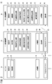
- FIG. 2 is a block diagram illustrating an industrial wireless communication system according to one embodiment.
- FIG. 3 is a diagram conceptually showing transmission and reception of a synchronous connection signal.
- FIG. 4 is a diagram showing an example of a time chart.
- 5A and 5B are time charts showing an example of the order of switching communication frequencies for synchronization.
- FIG. 6 is a diagram illustrating an example of the operation of an industrial wireless communication system according to one embodiment.
- FIG. 7 is a diagram illustrating an example of the operation of an industrial wireless communication system according to one embodiment.
- FIG. 8 is a diagram illustrating an example of the operation of an industrial wireless communication system according to one embodiment.
- FIG. 9 is a diagram illustrating an example of the operation of an industrial wireless communication system according to one embodiment.
- FIG. 10 is a time chart showing an example of the interrupt period Tir.
- FIG. 1 is a diagram showing the configuration of an industrial wireless communication system according to this embodiment.
- FIG. 2 is a block diagram showing an industrial wireless communication system according to this embodiment.
- the industrial wireless communication system 10 includes a computer 12, a base wireless device 14, and a remote wireless device 16.
- the industrial wireless communication system 10 is equipped with a plurality of base wireless devices 14 .
- a single computer 12 and multiple base wireless devices 14 may be connected via a fieldbus 17 .
- Multiple remote radios 16 may be synchronously connected to one base radio 14 .
- Multiple networks 43 can be configured by synchronously connecting multiple remote wireless devices 16 to each base wireless device 14 .
- the computer 12 can monitor and control industrial equipment.
- Such computer 12 may be configured by, for example, a PLC (Programmable Logic Controller), but is not limited to this.
- the computer 12 includes, for example, an arithmetic section (processing section) 18 and a storage section 19 .
- the computing unit 18 may be configured by a processor such as a CPU (Central Processing Unit), for example. That is, the arithmetic unit 18 can be configured by a processing circuit.
- the calculation unit 18 is provided with a control unit 20 .
- the calculation unit 18 may also include components other than the control unit 20, but the components other than the control unit 20 are omitted here for simplification of explanation.
- the control unit 20 controls the entire computer 12 .
- the control unit 20 can monitor and control industrial equipment.
- the control unit 20 can be implemented by executing a program stored in the storage unit 19 by the calculation unit 18 .
- At least part of the control unit 20 may be implemented by an integrated circuit such as an ASIC (Application Specific Integrated Circuit) or an FPGA (Field-Programmable Gate Array).
- at least part of the control unit 20 may be configured by an electronic circuit including a discrete device.
- the storage unit 19 can be composed of a volatile memory (not shown) and a non-volatile memory (not shown). Volatile memory may include, for example, RAM (Random Access Memory). Examples of nonvolatile memory include ROM (Read Only Memory), flash memory, and the like. Data and the like may be stored, for example, in volatile memory. Programs, tables, maps, etc. may be stored, for example, in non-volatile memory. At least part of the storage unit 19 may be provided in the processor, integrated circuit, or the like as described above.
- the computer 12 is equipped with an input/output interface 21 for realizing fieldbus connection.
- Computer 12 may communicate with base wireless device 14 via fieldbus 17 .
- the base radio device 14, that is, the master radio device is provided with, for example, a calculation unit (processing unit) 22 and a storage unit 23.
- the calculation unit 22 may be configured by a processor (processing circuit) such as a CPU, for example.
- the calculation unit 22 includes a control unit 24 , a synchronous connection transmission unit 25 , a transmission/reception processing unit 26 , a connection state determination unit 27 and a forced disconnection signal transmission unit 28 .
- the computing unit 22 may be provided with components other than these components, but here, components other than these components are omitted for simplification of explanation.
- the control unit 24, the synchronous connection transmission unit 25, the transmission/reception processing unit 26, the connection state determination unit 27, and the forced disconnection signal transmission unit 28 are executed by the calculation unit 22 according to the program stored in the storage unit 23.
- At least part of the control unit 24, the synchronous connection transmission unit 25, the transmission/reception processing unit 26, the connection state determination unit 27, and the forced disconnection signal transmission unit 28 may be realized by an integrated circuit such as ASIC or FPGA. At least part of the control unit 24, the synchronous connection transmission unit 25, the transmission/reception processing unit 26, the connection state determination unit 27, and the forced disconnection signal transmission unit 28 may be configured by electronic circuits including discrete devices.
- the storage unit 23 can be composed of a volatile memory (not shown) and a non-volatile memory (not shown). Volatile memory may include, for example, RAM and the like. Non-volatile memory may include, for example, ROM, flash memory, and the like. Data and the like may be stored, for example, in volatile memory. Programs, tables, maps, etc. may be stored, for example, in non-volatile memory. At least part of the storage unit 23 may be provided in the processor, integrated circuit, or the like as described above.
- the base wireless device 14 is equipped with an input/output interface 29 for realizing fieldbus connection.
- Base wireless device 14 may be connected to computer 12 by fieldbus 17, as described above.
- the base radio device 14 is equipped with a communication section 30 for radio communication.
- the base radio 14 may communicate wirelessly with the remote radios 16 using the communication portion 30 .
- a remote radio device 16 ie, a slave radio device, can be provided in each of a plurality of devices 44 (see FIG. 1) that constitute industrial equipment. Such devices 44 may include, but are not limited to, sensors, valves, and the like.
- the remote wireless device 16 includes, for example, an arithmetic unit (processing unit) 32 and a storage unit 34 .
- the computing unit 32 may be configured by, for example, a processor (processing circuit) such as a CPU.
- the calculation unit 32 includes a control unit 35, a synchronous connection reception unit 36, a transmission/reception processing unit 37, a reception completion notification transmission unit 38, a forced disconnection signal transmission unit 39, a diagnostic information transmission unit 40, and a power supply monitoring unit. 41 are provided.
- the computing unit 32 may also include components other than these components, but here, components other than these components are omitted for simplification of explanation.
- the control unit 35 , the synchronous connection reception unit 36 , the transmission/reception processing unit 37 , and the reception completion notification transmission unit 38 can be realized by the operation unit 32 executing a program stored in the storage unit 34 .
- the forced disconnection signal transmission unit 39 , the diagnostic information transmission unit 40 , and the power supply monitoring unit 41 can be realized by executing a program stored in the storage unit 34 by the calculation unit 32 .
- At least part of the control unit 35, the synchronous connection receiving unit 36, the transmission/reception processing unit 37, the reception completion notification transmission unit 38, the forced disconnection signal transmission unit 39, the diagnostic information transmission unit 40, and the power supply monitoring unit 41 is implemented as an ASIC or an FPGA. It may be implemented by an integrated circuit such as.
- control unit 35 the synchronous connection reception unit 36, the transmission/reception processing unit 37, the reception completion notification transmission unit 38, the forced disconnection signal transmission unit 39, the diagnostic information transmission unit 40, and the power supply monitoring unit 41 can It may be configured by an electronic circuit including:
- the storage unit 34 can be composed of a volatile memory (not shown) and a non-volatile memory (not shown). Volatile memory may include, for example, RAM and the like. Non-volatile memory may include, for example, ROM, flash memory, and the like. Data and the like may be stored, for example, in volatile memory. Programs, tables, maps, etc. may be stored, for example, in non-volatile memory. At least a portion of the storage unit 34 may be provided in the processor, integrated circuit, or the like as described above.
- the remote wireless device 16 is equipped with a communication unit 42 for wireless communication. Remote wireless device 16 may communicate wirelessly with base wireless device 14 using communication unit 42 .
- Frequency hopping communication can be performed between the base radio device 14 and the remote radio device 16 . That is, data can be transmitted and received between the base radio device 14 and the remote radio device 16 by switching the hopping frequency at a predetermined hopping period Tfh. Hopping frequency switching may be performed based on a predetermined hopping pattern. Since the same hopping pattern is used for the base radio device 14 and the remote radio device 16 that are synchronously connected to each other, communication can be performed while switching the communication frequency between the base radio device 14 and the remote radio device 16 .
- the communication frequency is the frequency of the carrier wave. Processing of frequency hopping communication is managed by a transmission/reception processing unit 26 provided in the base radio device 14 and a transmission/reception processing unit 37 provided in the remote radio device 16 . That is, data transmission/reception processing in the frequency hopping method is managed by a transmission/reception processing unit 26 provided in the base radio device 14 and a transmission/reception processing unit 37 provided in the remote radio device 16 .
- the 2.4 GHz band can be used for wireless communication using the frequency hopping method. Assuming that the minimum frequency is 2403 MHz, the maximum frequency is 2481 MHz, and the frequency band occupied by each channel is 1 MHz wide, the number of channels is 79.
- Pairing may be performed in advance between the base wireless device 14 and the remote wireless device 16 . Even if the base wireless device 14 and the remote wireless device 16 have already been paired, if the base wireless device 14 and the remote wireless device 16 are not synchronously connected, between the base wireless device 14 and the remote wireless device 16 Frequency hopping communication cannot be performed. For this reason, transmission and reception of a synchronous connection signal for establishing a synchronous connection are performed between the base radio device 14 and the remote radio device 16 prior to performing frequency hopping communication.
- the synchronous connection signal can include identification information of the base radio device 14, identification information of the remote radio device 16 to which the synchronous connection signal is to be sent, and time information.
- the identification information of the base radio device 14 is, for example, the product ID of the base radio device 14, but is not limited to this.
- the identification information of the remote wireless device 16 is, for example, the product ID of the remote wireless device 16, but is not limited to this.
- Transmission and reception of a synchronous connection signal for establishing a synchronous connection can be performed, for example, in the following cases.
- a network 43 that has not been activated is activated, synchronous connection signals are transmitted and received between all of the plurality of remote wireless devices 16 constituting the network 43 and the base wireless device 14 .
- transmission and reception of a synchronous connection signal can be performed between the remote radio device 16 and the base radio device 14 .
- a disconnected state is a state in which the remote wireless device 16 is not synchronously connected to the base wireless device 14 .
- the base radio device 14 is provided with the synchronous connection transmission section 25 as described above.
- the synchronous connection transmission unit 25 provided in the base radio device 14 performs the following: Do something like That is, in such a case, the synchronous connection transmission unit 25 performs transmission processing for transmitting a synchronous connection signal for establishing a synchronous connection with the remote wireless device 16 that is not synchronously connected.
- Such transmission processing can be performed by broadcasting to a plurality of remote wireless devices 16 forming the network 43 .
- Such transmission processing is performed only in a single synchronous connection cycle Tsc that is an integral multiple of the hopping cycle Tfh.
- Such transmission processing is performed only in the predetermined synchronous connection cycle Tsc.
- such transmission processing can be performed at predetermined interrupt intervals.
- the synchronous connection period Tsc can be set to 250 msec, for example, but is not limited to this.
- Signals for maintaining the synchronous connection may also be transmitted and received between the base radio device 14 and the remote radio device 16 that are synchronously connected.
- Transmission and reception of signals for maintaining synchronous connection may be performed by wireless communication in a frequency hopping scheme.
- Transmission and reception of a signal for maintaining a synchronous connection can be performed, for example, at a period of 100 msec, but is not limited to this.
- a signal for maintaining a synchronous connection signal may include time information. Therefore, the time difference between the time information of the base radio device 14 and the time information of the remote radio device 16 can be eliminated by transmitting and receiving signals for maintaining a synchronous connection.
- the reason why the synchronous connection signal is transmitted only in the synchronous connection period Tsc is that, in periods other than the synchronous connection period Tsc, the data transmission in the frequency hopping method is performed between the remote radio apparatus 16 and the base radio apparatus 14 which have already been synchronously connected. is transmitted and received. That is, the synchronous connection signal for synchronous connection is transmitted only at a predetermined synchronous connection period Tsc in order to prevent interference with data transmission and reception in the frequency hopping system.
- the synchronous connection transmission unit 25 sequentially switches the communication frequency for synchronization, which is the communication frequency for synchronization, to transmit the synchronous connection signal at a plurality of communication frequencies for synchronization within one hopping period Tfh.
- the reason why a plurality of communication frequencies for synchronization are used when transmitting a synchronous connection signal is as follows. That is, even if transmission/reception of a synchronous connection signal at a certain synchronous communication frequency is hindered by radio wave interference or the like, the synchronous connection signal can be transmitted/received at a synchronous communication frequency different from the synchronous communication frequency. This is because there are cases. For this reason, multiple synchronization communication frequencies are used when transmitting the synchronization connection signal.
- the remote wireless device 16 is provided with the synchronous connection receiving section 36 as described above.
- the synchronous connection reception unit 36 waits for reception of a synchronous connection signal.
- the synchronous connection signal reception waiting process is performed at a plurality of synchronous communication frequencies by sequentially switching the synchronous communication frequencies at a predetermined switching cycle Tcg.
- a plurality of synchronous communication frequencies used when transmitting a synchronous connection signal and a plurality of synchronous communication frequencies used when waiting for reception are set in the same manner.
- the plurality of synchronizing communication frequencies used when one base radio device 14 transmits a synchronous connection signal are f1, f2, and f3
- the plurality of synchronizing communication frequencies used by the remote radio device 16 during reception waiting processing are also set to f1, f2, and f3.
- the A synchronous connection signal cannot be received by the remote wireless device 16 .
- the synchronization is performed. A connection signal may be received by the remote wireless device 16 .
- This switching cycle Tcg is set to a cycle longer than the hopping cycle Tfh and shorter than twice the hopping cycle Tfh.
- the switching period Tcg is set in this manner for the following reasons. That is, when the switching cycle Tcg is set in this manner, the relative time relationship between the timing of the synchronous connection signal transmission process and the timing of switching the synchronization communication frequency in the reception wait process gradually changes over time. change to Then, the synchronizing communication frequency used for the transmission process and the synchronizing communication frequency used for the reception waiting process quickly match. For this reason, the switching period Tcg is set to be longer than the hopping period Tfh and shorter than twice the hopping period Tfh.
- the hopping cycle Tfh is, for example, 5 msec or less, but is not limited to this. However, from the viewpoint of realizing high-speed communication by the hopping method, it is preferable that the hopping cycle Tfh is 5 msec or less.
- the hopping period Tfh is 5 msec will be described as an example.
- the switching period Tcg can be set to 6 msec, for example, but is not limited to this.
- the number of synchronizing communication frequencies used in the transmission process and the reception waiting process can be set to 3, for example, but is not limited to this.
- the number of synchronization communication frequencies used in the transmission process and the reception wait process may be two or four, for example.
- a case where the number of synchronization communication frequencies used in the transmission process and the reception wait process is three will be described as an example.
- the control unit 35 When the synchronous connection signal is received by the transmission/reception processing unit 37, the control unit 35 provided in the remote wireless device 16 performs the following processing. That is, in such a case, the control unit 35 determines whether or not the synchronous connection signal is the synchronous connection signal transmitted from the base radio device 14 to the remote radio device 16 based on the information included in the synchronous connection signal. to judge. Specifically, based on the identification information of the base radio device 14 and the identification information of the remote radio device 16, the control unit 35 transmits the synchronous connection signal to the remote radio device 16. determines whether it is a synchronous connection signal transmitted from the
- FIG. 3 is a diagram conceptually showing transmission and reception of a synchronous connection signal.
- the vertical direction in FIG. 3 indicates elapsed time from a certain timing.
- the base radio device 14 transmits the synchronous connection signal at the synchronous connection period Tsc.
- the synchronous connection signal transmission process is performed within the hopping cycle Tfh.
- the remote wireless device 16 switches the communication frequency for synchronization in the reception waiting process at the predetermined switching cycle Tcg.
- FIG. 3 shows an example where the switching period Tcg is 6 msec.
- a synchronous connection signal with a synchronous communication frequency of f1 there are a synchronous connection signal with a synchronous communication frequency of f1, a synchronous connection signal with a synchronous communication frequency of f2, and a synchronous communication frequency of f3.
- a synchronous connection signal is transmitted from the base radio unit 14 .
- the transmission processing of the synchronous connection signal from the base radio apparatus 14 is performed in the hopping cycle Tfh when the elapsed time is 0 msec.
- the transmission processing of the synchronous connection signal from the base radio apparatus 14 is performed in the hopping cycle Tfh when the elapsed time is 250 msec.
- the transmission processing of the synchronous connection signal from the base radio apparatus 14 is performed in the hopping cycle Tfh when the elapsed time is 500 msec. If there is a remote radio device 16 that has not been synchronously connected, the process of transmitting a synchronous connection signal from the base radio device 14 can be similarly performed every time, for example, 250 msec. Now, we omit the explanation.
- the timing of switching the communication frequency for synchronization in the reception waiting process is different from each other by 1 msec among the plurality of remote wireless devices 16A to 16P.
- Reference numeral 16 is used when describing remote wireless devices in general, and reference numerals 16A-16P are used when describing individual remote wireless devices 16.
- the switching timings of the synchronization communication frequencies in the reception waiting process are shown shifted by 1 msec from each other in the plurality of remote radio apparatuses 16A to 16P.
- the communication frequency for synchronization in the reception waiting process is set to f1 by the remote wireless device 16A.
- the communication frequency for synchronization in the reception waiting process is set to f2 by the remote wireless device 16A.
- the synchronization communication frequency is set to f3 by the remote wireless device 16A in the reception waiting process.
- the remote radio device 16A keeps switching the communication frequency for synchronization in the reception waiting process in the order of f1, f2, and f3 in the same manner as described above until a synchronous connection with the base radio device 14 is established.
- the timing at which the synchronization communication frequency is switched in the remote radio device 16B in the reception waiting process is delayed by 1 msec with respect to the timing at which the synchronization communication frequency is switched in the remote radio device 16A in the reception waiting process. ing. That is, in the example shown in FIG. 3, when the elapsed time is 1 msec, 7 msec, 13 msec, .
- the remote radio device 16B also sets the communication frequency for synchronization in the receive waiting process to f1, f2, and f3 in the order described above until a synchronous connection with the base radio device 14 is established. keep switching.
- the timing of switching the communication frequency for synchronization in the reception waiting process is different from each other by 1 msec among the plurality of remote wireless devices 16A to 16P.
- the remote radio devices 16C to 16P also set the synchronous communication frequencies to f1 and f2 in the reception waiting process until the synchronous connection with the base radio device 14 is established. , f3.
- the example shown in FIG. 3 is as follows. That is, in the example shown in FIG. 3, when the elapsed time is 0 msec, the synchronous connection signal is transmitted from the base radio apparatus 14 at the synchronous communication frequency f1. When the elapsed time is 0 msec, the communication frequency for synchronization in the reception waiting process is set to f1 in the remote wireless device 16A. Therefore, the remote radio device 16A receives the synchronous connection signal transmitted from the base radio device 14 at the communication frequency f1 for synchronization when the elapsed time is 0 msec.
- the synchronous connection signal is transmitted from the base radio unit 14 at the synchronous communication frequency f2.
- the communication frequency for synchronization in the reception waiting process is set to f1 in the remote wireless device 16A. Therefore, the synchronous connection signal transmitted from the base radio device 14 at the communication frequency f2 for synchronization when the elapsed time is 2 msec is not received by the remote radio device 16A.
- the synchronous connection signal is transmitted from the base radio unit 14 at the synchronous communication frequency f3.
- the communication frequency for synchronization in the reception waiting process is set to f1 in the remote wireless device 16A. Therefore, the synchronous connection signal transmitted from the base radio device 14 at the communication frequency f3 for synchronization when the elapsed time is 4 msec is not received by the remote radio device 16A.
- the example shown in FIG. 3 is as follows. That is, in the example shown in FIG. 3, when the elapsed time is 250 msec, the synchronous connection signal is transmitted from the base radio apparatus 14 at the synchronous communication frequency f1. When the elapsed time is 250 msec, the communication frequency for synchronization in the reception waiting process is set to f2 in the remote wireless device 16K. Therefore, the synchronous connection signal transmitted from the base radio device 14 at the communication frequency f1 for synchronization when the elapsed time is 250 msec is not received by the remote radio device 16K.
- the synchronous connection signal is transmitted from the base radio unit 14 at the synchronous communication frequency f2.
- the communication frequency for synchronization in the reception waiting process is set to f2 in the remote wireless device 16K. Therefore, the synchronous connection signal transmitted from the base radio device 14 at the communication frequency f2 for synchronization when the elapsed time is 252 msec is received by the remote radio device 16K.
- the base radio unit 14 transmits the synchronization connection signal at the synchronization communication frequency f3.
- the communication frequency for synchronization in the reception waiting process is set to f2 in the remote wireless device 16K. Therefore, the synchronous connection signal transmitted from the base radio device 14 at the communication frequency f3 for synchronization when the elapsed time is 254 msec is not received by the remote radio device 16K.
- the example shown in FIG. 3 is as follows. That is, in the example shown in FIG. 3, when the elapsed time is 500 msec, the synchronous connection signal is transmitted from the base radio apparatus 14 at the synchronous communication frequency f1. When the elapsed time is 500 msec, the communication frequency for synchronization in the reception waiting process is set to f2 in the remote wireless device 16D. Therefore, the synchronous connection signal transmitted from the base radio device 14 at the communication frequency f1 for synchronization when the elapsed time is 500 msec is not received by the remote radio device 16D.
- the synchronous connection signal is transmitted from the base radio unit 14 at the synchronous communication frequency f2.
- the communication frequency for synchronization in the reception waiting process is set to f3 in the remote wireless device 16D. Therefore, the synchronous connection signal transmitted from the base radio device 14 at the communication frequency f2 for synchronization when the elapsed time is 502 msec is not received by the remote radio device 16D.
- the base radio unit 14 transmits the synchronization connection signal at the synchronization communication frequency f3.
- the communication frequency for synchronization in the reception waiting process is set to f3 in the remote wireless device 16D. Therefore, the synchronous connection signal transmitted from the base radio device 14 at the communication frequency f3 for synchronization when the elapsed time is 504 msec is received by the remote radio device 16D.
- the remote wireless device 16 is provided with the reception completion notification transmission section 38 as described above.
- the reception completion notification transmitting unit 38 sends a A reception completion notification Ack may be sent. That is, when the control unit 35 determines that the signal is a synchronous connection signal sent to the remote wireless device 16, the reception completion notification sending unit 38 performs the following processing. In such a case, the reception completion notification transmitting unit 38 transmits a reception completion notification Ack to the base radio device 14 in the next hopping cycle Tfh after the hopping cycle Tfh in which the synchronous connection signal was received. Note that such a reception completion notification Ack can be performed in data transmission/reception in the frequency hopping system.
- the reception completion notification Ack is received by the base radio device 14, the synchronous connection processing between the base radio device 14 and the remote radio device 16 is completed.
- FIG. 4 is a diagram showing an example of a time chart.
- FIG. 4 shows the synchronous connection signal Tx transmitted from the base radio device 14 and the reception completion notification Ack returned from the remote radio device 16 which is the destination of the synchronous connection signal Tx.
- the synchronous connection signal is transmitted by switching the communication frequency for synchronization in the order of f1, f2, and f3.
- the symbol Tfh is used, and when describing the individual hopping cycles, the symbols Tfh(1), Tfh(2), . . . , Tfh(n) are used.
- the remote radio device 16 When the synchronous connection signal is received by the remote radio device 16 that is the destination of the synchronous connection signal, the remote radio device 16 notifies reception completion in the hopping period Tfh(2) next to the hopping period Tfh(1). Ack is returned.
- the number of channels is, for example, 79. Since the number of channels, that is, the number of communication frequencies for synchronization is limited to, for example, 79, the following may occur in the industrial wireless communication system 10 provided with a large number of base wireless devices 14 . That is, the combination of a plurality of communication frequencies for synchronization used when transmitting the synchronous connection signal may match between one base radio device 14 and another base radio device 14 .
- a plurality of communication frequencies for synchronization used in transmission processing for transmitting a synchronous connection signal are the same between one base radio device 14 and another base radio device 14, transmission of the synchronous connection signal is hindered by radio wave interference. increase the likelihood of being In such a case, the switching order of a plurality of communication frequencies for synchronization is made different among the base radio apparatuses 14, thereby suppressing the transmission of the synchronization connection signal from being hindered by radio wave interference.
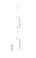
- FIGS. 5A and 5B are time charts showing an example of the switching order of the synchronization communication frequencies.
- FIG. 5A shows an example for this embodiment. That is, FIG. 5A shows an example in which the switching order of a plurality of communication frequencies for synchronization is made different from each other.
- FIG. 5B shows an example for the comparative example. That is, FIG. 5B shows an example in which the same switching order is set for a plurality of synchronization communication frequencies.
- FIGS. 5A and 5B show examples in which the synchronous connection cycle Tsc1 in one base radio device 14 and the synchronous connection cycle Tsc2 in another base radio device 14 overlap each other. In the example shown in FIGS.
- Tx1 in FIGS. 5A and 5B indicates a synchronous connection signal transmitted from one base radio device 14.
- Tx2 in FIGS. 5A and 5B indicates a synchronous connection signal transmitted from another base radio device 14.
- one base radio device 14 switches the communication frequency for synchronization in the order of f1, f2, and f3 when transmitting the synchronous connection signal.
- Other base radio apparatuses 14 also switch the communication frequency for synchronization in the order of f1, f2, and f3 when transmitting the synchronous connection signal.
- the synchronous connection cycle Tsc1 in one base radio device 14 and the synchronous connection cycle Tsc2 in the other base radio device 14 overlap with each other. become.
- one base radio apparatus 14 transmits a synchronous connection signal at the communication frequency f1 for synchronization
- another base radio apparatus 14 transmits a synchronous connection signal at the communication frequency f1 for synchronization. Since the synchronous communication frequency is the same when transmitting the synchronous connection signal, radio wave interference occurs when the synchronous connection signal is transmitted at the synchronous communication frequency f1. Also, when one base radio apparatus 14 transmits a synchronous connection signal at the communication frequency f2 for synchronization, another base radio apparatus 14 transmits a synchronous connection signal at the communication frequency f2 for synchronization. Since the communication frequency for synchronization is the same when transmitting the synchronous connection signal, radio wave interference occurs even when the synchronous connection signal is transmitted at the communication frequency for synchronization f2.
- one base radio apparatus 14 transmits a synchronous connection signal at the communication frequency f3 for synchronization
- another base radio apparatus 14 transmits a synchronous connection signal at the communication frequency f3 for synchronization. Since the synchronous communication frequency is the same when transmitting the synchronous connection signal, radio wave interference occurs when the synchronous connection signal is transmitted at the synchronous communication frequency f3.
- one base radio apparatus 14 switches the communication frequency for synchronization in the order of f1, f2, and f3 when transmitting a synchronous connection signal, for example. Further, in this embodiment, as shown in FIG. 5A, the other base radio apparatus 14 switches the communication frequency for synchronization in the order of f3, f2, and f1 when transmitting the synchronous connection signal, for example.
- the synchronization communication frequencies are switched in this order, even if the synchronous connection cycle Tsc1 in one base radio device 14 and the synchronous connection cycle Tsc2 in the other base radio device 14 overlap each other, the following become.
- the other base radio apparatus 14 transmits a synchronous connection signal at the communication frequency f3 for synchronization. Since the communication frequencies for synchronization when transmitting the synchronous connection signal are different from each other, radio wave interference does not occur between them. Further, when one base radio apparatus 14 transmits a synchronous connection signal at the communication frequency f3 for synchronization, the other base radio apparatus 14 transmits a synchronous connection signal at the communication frequency f1 for synchronization. Since the communication frequencies for synchronization when transmitting the synchronous connection signal are different from each other, radio wave interference does not occur between them. Radio wave interference occurs only when synchronization connection signals are transmitted from one base radio device 14 and another base radio device 14 at the communication frequency f2 for synchronization.
- a plurality of communication frequencies for synchronization used when transmitting a synchronization connection signal matches each other among a plurality of base radio apparatuses 14, a plurality of communication frequencies for synchronization are used. are made different among these base radio units 14 . By doing so, it is possible to prevent the transmission of the synchronous connection signal from being hindered by radio wave interference.
- the power of the synchronously connected remote wireless device 16 may be turned off. Whether or not the remote wireless device 16 is in the disconnected state can be determined, for example, as follows. That is, when the base radio device 14 and the remote radio device 16 are synchronously connected, data indicating that the remote radio device 16 is in a connected state is sent from the remote radio device 16 every two seconds, for example. It is transmitted to the base radio unit 14 concerned. When the remote wireless device 16 becomes disconnected, data indicating that the remote wireless device 16 is connected is no longer transmitted from the remote wireless device 16 to the base wireless device 14. . In the present embodiment, when data is not newly received from the remote wireless device 16 even though the elapsed time from the timing at which the data was received reaches the time threshold TTH, the following processing is performed. is done.
- the connection state determination unit 27 determines that the remote wireless device 16 is in the non-connection state.
- the time threshold TTH can be, for example, 5 seconds, but is not limited to this.
- the remote wireless device 16 A non-connected state is determined. Therefore, in this embodiment, when the power of the remote wireless device 16 is turned off, it can be accurately determined that the remote wireless device 16 is in the non-connected state. Diagnostic information, which is information indicating whether or not the device 44 provided with the remote wireless device 16 has an abnormality, is transmitted together with data indicating that the remote wireless device 16 is in a connected state. may be
- FIG. 6 is a diagram showing an example of the operation of the industrial wireless communication system according to this embodiment.
- FIG. 6 shows an example in which it is determined that the remote wireless device 16 is in a non-connected state based on the fact that the time during which no data is received from the remote wireless device 16 reaches the time threshold TTH. ing.
- step S ⁇ b>1 the connection state determination unit 27 determines whether or not the base wireless device 14 has received data from the remote wireless device 16 . If the base radio device 14 has received the data from the remote radio device 16 (YES in step S1), the processing shown in FIG. 6 is completed. If the base radio device 14 does not receive the data from the remote radio device 16 (NO in step S1), the process proceeds to step S2.
- step S2 the connection state determination unit 27 determines whether or not the elapsed time from the timing of receiving the data from the remote wireless device 16 has reached the time threshold TTH.
- the process proceeds to step S3. If the elapsed time from the timing of receiving the data from the remote wireless device 16 has not reached the time threshold TTH (NO in step S2), the processes after step S1 are repeated.
- step S3 the connection state determination unit 27 determines that the remote wireless device 16 is in a non-connection state. Thus, the processing shown in FIG. 6 is completed.
- the base radio device 14 may be determined in the following manner that the remote wireless device 16 is in a non-connected state. That is, when data is transmitted from the base radio device 14 to the remote radio device 16 but the reception completion notification Ack is not transmitted from the remote radio device 16, the base radio device 14 performs the following. such processing. In such a case, the base radio device 14 retransmits the data to the remote radio device 16 . That is, in such a case, the base radio device 14 performs a retry. Even if the reception completion notification Ack from the remote radio device 16 is not received, the base radio device 14 retransmits the data until the number of times threshold NTH is reached.
- the remote wireless device 16 when the reception completion notification Ack from the remote wireless device 16 is not received even though the repetition of data transmission reaches the number threshold value NTH, the remote wireless device 16 is in the non-connected state.
- the connection state determination unit 27 determines that there is.
- the number of times threshold NTH can be, for example, 32 times, but is not limited to this. In this way, even though the number of repetitions of data transmission to the remote radio device 16 synchronously connected has reached the threshold value NTH, based on the fact that the reception completion notification Ack has not been received, the remote radio device 16 It may be determined that device 16 is unconnected.
- FIG. 7 is a diagram showing an example of the operation of the industrial wireless communication system according to this embodiment.
- FIG. 7 shows an example in which it is determined that the remote wireless device 16 is in a non-connected state based on the fact that the number of repetitions of data transmission to the remote wireless device 16 has reached the frequency threshold value NTH.
- step S11 the transmission/reception processing unit 26 transmits data to the remote wireless device 16 using the frequency hopping method. After that, the process transitions to step S12.
- step S ⁇ b>12 the connection state determination unit 27 determines whether or not the reception completion notification Ack from the remote wireless device 16 has been received by the transmission/reception processing unit 26 .
- the reception completion notification Ack from the remote wireless device 16 is received by the transmission/reception processing unit 26 (YES in step S12)
- the processing shown in FIG. 7 is completed. If the reception completion notification Ack from the remote radio device 16 has not been received by the transmission/reception processing unit 26 (NO in step S12), the process proceeds to step S13.
- step S13 the connection state determination unit 27 determines whether or not the number of repetitions of data transmission to the remote wireless device 16 has reached the number threshold NTH. If the number of repetitions of data transmission to the remote wireless device 16 has not reached the number of times threshold NTH (NO in step S13), the processes after step S11 are repeated. When the number of repetitions of data transmission to the remote wireless device 16 reaches the number threshold NTH (YES in step S13), the process proceeds to step S14.
- step S14 the connection state determination unit 27 determines that the remote wireless device 16 is in a non-connection state. Thus, the processing shown in FIG. 7 is completed.
- the base radio device 14 has a function of forcibly cutting off the connection state with the synchronously connected remote radio device 16 . That is, the base radio device 14 is provided with the forced disconnection signal transmission section 28 as described above.
- the forced disconnection signal transmission unit 28 can transmit a forced disconnection signal for forcibly disconnecting the connection with one remote wireless device 16 that is synchronously connected to the one remote wireless device 16. .
- the connection state determination unit 27 provided in the base wireless device 14 determines that the one remote wireless device 16 is disconnected. state.
- FIG. 8 is a diagram showing an example of the operation of the industrial wireless communication system according to this embodiment.
- FIG. 8 shows an example of determining that the remote wireless device 16 is in a non-connected state when the forced disconnection signal is transmitted to the remote wireless device 16 by the forced disconnection signal transmitting unit 28 . .
- step S21 the connection state determination unit 27 determines whether a forced disconnection signal has been transmitted to the remote wireless device 16 by the forced disconnection signal transmission unit 28.
- the process proceeds to step S22. If the forced disconnection signal transmission unit 28 has not transmitted the forced disconnection signal to the remote wireless device 16 (NO in step S21), the process shown in FIG. 8 is completed.
- step S22 the connection state determination unit 27 determines that the remote wireless device 16 is in the non-connection state. Thus, the processing shown in FIG. 8 is completed.
- the remote radio device 16 has a function of forcibly cutting off the connection state with the synchronously connected base radio device 14 . That is, the remote wireless device 16 is provided with the forced disconnection signal transmission section 39 and the power supply monitoring section 41 as described above.
- the forced disconnection signal transmission unit 39 can transmit a forced disconnection signal for forcibly disconnecting the synchronous connection between the remote radio device 16 and the base radio device 14 to the one base radio device 14 .
- the forced disconnection signal transmission unit 39 sends a forced disconnection signal for forcibly disconnecting the synchronous connection to the base radio device 14. can be sent
- the connection state determination unit 27 provided in the base radio device 14 can determine that the remote radio device 16 is in the non-connection state.
- a forced disconnection signal is transmitted from the remote wireless device 16 when the power supply voltage monitored by the power supply monitoring unit 41 becomes less than the voltage threshold
- the present invention is not limited to this. not something.
- the remote radio device 16 sends a request to the base radio device 14 A forced disconnection signal may be sent.
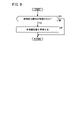
- FIG. 9 is a diagram showing an example of the operation of the industrial wireless communication system according to this embodiment.
- FIG. 9 shows an example of determining that the remote wireless device 16 is in a non-connected state when a forced disconnection signal is received from the remote wireless device 16 .
- step S ⁇ b>31 the connection state determination unit 27 determines whether or not the transmission/reception processing unit 26 has received a forced disconnection signal from the remote wireless device 16 .
- the process proceeds to step S32. If the forced disconnection signal has not been received by the transmission/reception processing unit 26 (NO in step S31), the process shown in FIG. 9 is completed.
- step S32 the connection state determination unit 27 determines that the remote wireless device 16 is in a non-connection state. Thus, the processing shown in FIG. 9 is completed.
- the base radio device 14 When the connection with the synchronously connected remote radio device 16 is disconnected, the base radio device 14 performs processing for transmitting a synchronous connection signal for reestablishing synchronous connection with the remote radio device 16. . That is, the synchronous connection transmission unit 25 provided in the base radio device 14 performs the following processing when the connection with the remote radio device 16 with which the synchronous connection has been made is disconnected. In such a case, the synchronous connection transmission unit 25 broadcasts a synchronous connection signal for reestablishing a synchronous connection with the remote wireless device 16 with which the synchronous connection has been established, at the synchronous connection period Tsc.
- the remote wireless device 16 is equipped with the diagnostic information transmission section 40 .
- the diagnostic information transmitter 40 may transmit diagnostic information of the equipment 44 on which the remote wireless device 16 is installed to the base wireless device 14 .
- Diagnostic information may include, for example, information indicating whether or not there is an abnormality in the equipment 44 provided with the remote wireless device 16 .
- Transmission and reception of such diagnostic information may be performed in transmission and reception of data in a frequency hopping manner. Transmission and reception of such diagnostic information may be performed in the transmission and reception of data in the frequency hopping method, and may also be performed in a predetermined interrupt period Tir.
- FIG. 10 is a time chart showing an example of the interrupt period Tir.
- the interrupt period Tir can be, for example, 500 msec, but is not limited to this.
- the synchronous connection signal for synchronously connecting to the remote radio device 16 is broadcast remotely from the base radio device 14 only in a single synchronous connection cycle Tsc that is an integral multiple of the hopping cycle Tfh. It is sent to the wireless device 16 .
- the synchronous connection signal is transmitted at a plurality of synchronous communication frequencies within one hopping cycle Tfh by sequentially switching the synchronous communication frequencies.
- a synchronous connection can be established with a plurality of communication frequencies for synchronization. Signal reception wait processing is performed. Therefore, according to the present embodiment, it is possible to provide the industrial wireless communication system 10 that can quickly establish a synchronous connection.
- the hopping cycle Tfh is 5 msec has been described as an example, but it is not limited to this.
- the hopping period Tfh may be, for example, 2 msec.
- the number of synchronization communication frequencies used in the transmission process and the reception wait process can be, for example, two, but is not limited to this.
- the number of synchronization communication frequencies used in the transmission process and the reception wait process may be, for example, three.
- the synchronous connection reception unit 36 can sequentially switch the communication frequency for synchronization at a period of, for example, 3 msec, but is not limited to this.
- An industrial wireless communication system (10) includes a computer (12) for monitoring and controlling industrial equipment, a base wireless device (14) connected to the computer via a field bus (17), and a plurality of and a plurality of remote radio devices (16) that are provided in each of the devices (44) and perform radio communication with the base radio device, and the base radio device and the remote radio device that are synchronously connected are preliminarily
- An industrial wireless communication system for transmitting and receiving data by switching a hopping frequency at a determined hopping cycle (Tfh), wherein the base wireless device is configured to perform the a synchronous connection transmission unit (25) that broadcasts a transmission process for transmitting a synchronous connection signal for synchronous connection to a remote wireless device only in a single synchronous connection cycle (Tsc) that is an integral multiple of the hopping cycle;
- the synchronous connection transmission unit sequentially switches the synchronous communication frequencies (f1, f2, f3), which are the synchronous communication frequencies, so that the synchronous communication frequencies are transmitted at a plurality of the synchronous communication frequencies
- a synchronous connection signal is transmitted, and when the remote radio device is not synchronously connected to the base radio device, the switching cycle ( Tcg), by sequentially switching the communication frequency for synchronization, a synchronous connection reception unit (36) that waits for reception of the synchronous connection signal at a plurality of the communication frequencies for synchronization.
- the synchronous connection signal for synchronously connecting to the remote wireless device is broadcast from the base wireless device to the remote wireless device only in a single synchronous connection cycle that is an integral multiple of the hopping cycle. be.
- the synchronous connection signal is transmitted at a plurality of synchronous communication frequencies within one hopping cycle by sequentially switching the synchronous communication frequencies.
- a plurality of networks (43) may be configured by having a plurality of the base radio devices and synchronously connecting a plurality of the remote radio devices to each of the base radio devices.
- the synchronous connection period may be 250 msec or less.
- the hopping period may be 5 msec or less.
- the hopping cycle may be 5 msec, and the number of the plurality of synchronization communication frequencies used in the transmission process and the reception wait process may be any one of 2-4.
- the synchronous connection reception unit may sequentially switch the communication frequency for synchronization at a cycle of 6 msec.
- the hopping period may be 2 msec, and the number of the plurality of synchronization communication frequencies used in the transmission process and the reception wait process may be two or three.
- the synchronous connection reception unit may sequentially switch the communication frequency for synchronization at a cycle of 3 msec.
- the synchronous connection signal may include identification information of the base radio apparatus, identification information of the remote radio apparatus to be synchronously connected, and time information.
- the remote radio apparatus When the synchronous connection signal is received by the synchronous connection receiving unit, the remote radio apparatus notifies the base radio apparatus of completion of reception in a hopping cycle next to the hopping cycle in which the synchronous connection signal was received.
- a reception completion notification transmission unit (38) for transmitting (Ack) may be further provided.
- the switching order of the plurality of synchronization communication frequencies may be made different among the plurality of base radio apparatuses having the same combination of the plurality of synchronization communication frequencies used in the transmission process. According to such a configuration, it is possible to prevent the transmission of the synchronous connection signal from being hindered by radio wave interference.
- the base radio receives data from the one of the remote radios with which it has a synchronous connection based on reaching a predetermined time threshold (TTH) without receiving data from the one of the remote radios.
- TTH time threshold
- a connection state determination unit (27) that determines that the device is in a non-connection state may be further provided. According to such a configuration, it is possible to accurately determine that the remote wireless device is in the disconnected state.
- the base wireless device receives data from the one remote wireless device even though the number of repetitions of transmission of data to the one remote wireless device with which a synchronous connection has been established has reached a number threshold (NTH). It may further include a connection state determination unit that determines that the one remote wireless device is in a non-connection state based on the fact that the completion notification has not been received. According to such a configuration, it is possible to accurately determine that the remote wireless device is in the disconnected state.
- NTH number threshold
- the base radio device transmits a forced disconnection signal to the one remote radio device for forcibly disconnecting the connection with the one remote radio device to which the synchronous connection is established. and a connection state for determining that said one remote wireless device is in a non-connected state when said forced disconnection signal is transmitted to said one remote wireless device by said forced disconnection signal transmitting unit. You may further have a determination part. According to such a configuration, it is possible to forcibly disconnect the synchronous connection with the remote wireless device, and to accurately determine that the remote wireless device has become disconnected.
- the remote radio device has a forced disconnection signal transmission unit (39) for transmitting to the base radio device a forced disconnection signal for forcibly disconnecting the connection with the base radio device synchronously connected to the base radio device.
- the base radio device further comprises a connection state determination unit that determines that the one remote radio device is in a non-connection state when the forced disconnection signal is received from the one remote radio device good. According to such a configuration, the synchronous connection with the base radio device can be forcibly disconnected from the remote radio device side, and the base radio device can accurately notify that the remote radio device has become disconnected. can judge.
- the synchronous connection transmission unit is configured to reestablish synchronous connection with the synchronously connected remote wireless device when the connection with the synchronously connected remote wireless device is disconnected. Transmission processing for transmitting the synchronous connection signal at the synchronous connection cycle is performed by broadcasting. According to such a configuration, the synchronous connection can be quickly restarted.
- the remote radio device has a diagnostic information transmission unit (40) for transmitting diagnostic information of the equipment provided with the remote radio device to the base radio device in data transmission/reception performed by switching the hopping frequency in the hopping period. may be further provided. With such a configuration, diagnostic information can be quickly communicated from the remote wireless device to the base wireless device.
Landscapes
- Engineering & Computer Science (AREA)
- Computer Networks & Wireless Communication (AREA)
- Signal Processing (AREA)
- Mobile Radio Communication Systems (AREA)
- Selective Calling Equipment (AREA)
Priority Applications (6)
| Application Number | Priority Date | Filing Date | Title |
|---|---|---|---|
| KR1020237028853A KR20230134580A (ko) | 2021-01-25 | 2021-08-20 | 산업용 무선 통신 시스템 |
| US18/261,232 US12301278B2 (en) | 2021-01-25 | 2021-08-20 | Industrial wireless communication system |
| EP21921120.8A EP4258757B1 (en) | 2021-01-25 | 2021-08-20 | Industrial wireless communication system |
| CN202180091794.5A CN116803151A (zh) | 2021-01-25 | 2021-08-20 | 工业用无线通信系统 |
| JP2022576955A JP7782467B2 (ja) | 2021-01-25 | 2021-08-20 | 産業用無線通信システム |
| IL304641A IL304641A (en) | 2021-01-25 | 2023-07-20 | The device that creates a pattern, a method for creating a pattern and a wireless communication system |
Applications Claiming Priority (2)
| Application Number | Priority Date | Filing Date | Title |
|---|---|---|---|
| JP2021-009661 | 2021-01-25 | ||
| JP2021009661 | 2021-01-25 |
Publications (1)
| Publication Number | Publication Date |
|---|---|
| WO2022158015A1 true WO2022158015A1 (ja) | 2022-07-28 |
Family
ID=82548660
Family Applications (1)
| Application Number | Title | Priority Date | Filing Date |
|---|---|---|---|
| PCT/JP2021/030506 Ceased WO2022158015A1 (ja) | 2021-01-25 | 2021-08-20 | 産業用無線通信システム |
Country Status (8)
| Country | Link |
|---|---|
| US (1) | US12301278B2 (https=) |
| EP (1) | EP4258757B1 (https=) |
| JP (1) | JP7782467B2 (https=) |
| KR (1) | KR20230134580A (https=) |
| CN (1) | CN116803151A (https=) |
| IL (1) | IL304641A (https=) |
| TW (1) | TWI912451B (https=) |
| WO (1) | WO2022158015A1 (https=) |
Families Citing this family (1)
| Publication number | Priority date | Publication date | Assignee | Title |
|---|---|---|---|---|
| EP4254097B1 (de) * | 2022-03-29 | 2025-05-28 | Siemens Aktiengesellschaft | Industrieanlage und verfahren zur grafischen darstellung von gleichlaufbeziehungen |
Citations (4)
| Publication number | Priority date | Publication date | Assignee | Title |
|---|---|---|---|---|
| JP2004282146A (ja) * | 2003-03-12 | 2004-10-07 | Sumitomo Electric Ind Ltd | 周波数ホッピング方式における同期確立方法 |
| JP2009159168A (ja) * | 2007-12-25 | 2009-07-16 | Fuji Electric Device Technology Co Ltd | 無線受信機 |
| JP5497730B2 (ja) | 2009-02-23 | 2014-05-21 | 三菱電機株式会社 | 無線通信システム、無線通信装置および無線通信方法 |
| JP2017188868A (ja) * | 2016-04-04 | 2017-10-12 | Smc株式会社 | 産業用無線通信システム |
Family Cites Families (17)
| Publication number | Priority date | Publication date | Assignee | Title |
|---|---|---|---|---|
| JPH0573795A (ja) | 1991-09-10 | 1993-03-26 | Smc Corp | 制御機器−センサ間の配線構造 |
| GB9304622D0 (en) * | 1993-03-06 | 1993-04-21 | Ncr Int Inc | Wireless local area network apparatus |
| AU1974795A (en) * | 1994-03-03 | 1995-09-18 | Proxim, Inc. | Frequency hopping medium access control protocol |
| US6014406A (en) | 1995-04-26 | 2000-01-11 | Hitachi, Ltd. | Frequency-hopped wireless communication system and mobile wireless terminal |
| GB0100093D0 (en) * | 2001-01-03 | 2001-02-14 | Vtech Communications Ltd | Adaptive frequency hopping strategy |
| US7532610B2 (en) * | 2001-01-16 | 2009-05-12 | Texas Instruments Incorporated | Structured adaptive frequency hopping |
| US20030147453A1 (en) * | 2002-02-06 | 2003-08-07 | Texas Instruments Incorporated | Adaptive frequency hopping communication scheme |
| US7254159B1 (en) * | 2002-02-20 | 2007-08-07 | Logitech Europe S.A. | High-frequency wireless peripheral device with auto-connection and auto-synchronization |
| US7577180B2 (en) * | 2003-12-18 | 2009-08-18 | Vtech Telecommunications Limited | Method and system for maintaining synchronization in low-power mode over a frequency hopping radio link |
| US8457798B2 (en) | 2006-03-14 | 2013-06-04 | Jamie Hackett | Long-range radio frequency receiver-controller module and wireless control system comprising same |
| US8018324B2 (en) | 2006-03-17 | 2011-09-13 | Rockwell Automation Technologies, Inc. | Sight-line non contact coupled wireless technology |
| CA2856027C (en) | 2014-03-18 | 2024-07-02 | Smartrek Technologies Inc. | MESH NETWORK SYSTEM AND TECHNIQUES |
| WO2016123208A1 (en) | 2015-01-30 | 2016-08-04 | Cassia Networks Inc. | Methods, devices and systems for increasing wireless communication range |
| US10009874B2 (en) | 2016-04-04 | 2018-06-26 | Smc Corporation | Industrial wireless communications system |
| US10659102B2 (en) * | 2017-02-04 | 2020-05-19 | Qualcomm Incorporated | Synchronization techniques using frequency hopping in unlicensed radio frequency spectrum |
| WO2019095300A1 (en) * | 2017-11-17 | 2019-05-23 | SZ DJI Technology Co., Ltd. | Systems and methods for synchronizing multiple control devices with a movable object |
| JP7013523B2 (ja) * | 2020-05-18 | 2022-01-31 | 株式会社東芝 | 無線通信装置、無線通信システム、無線通信方法及びプログラム |
-
2021
- 2021-08-20 KR KR1020237028853A patent/KR20230134580A/ko active Pending
- 2021-08-20 US US18/261,232 patent/US12301278B2/en active Active
- 2021-08-20 CN CN202180091794.5A patent/CN116803151A/zh active Pending
- 2021-08-20 JP JP2022576955A patent/JP7782467B2/ja active Active
- 2021-08-20 EP EP21921120.8A patent/EP4258757B1/en active Active
- 2021-08-20 WO PCT/JP2021/030506 patent/WO2022158015A1/ja not_active Ceased
-
2022
- 2022-01-19 TW TW111102212A patent/TWI912451B/zh active
-
2023
- 2023-07-20 IL IL304641A patent/IL304641A/en unknown
Patent Citations (4)
| Publication number | Priority date | Publication date | Assignee | Title |
|---|---|---|---|---|
| JP2004282146A (ja) * | 2003-03-12 | 2004-10-07 | Sumitomo Electric Ind Ltd | 周波数ホッピング方式における同期確立方法 |
| JP2009159168A (ja) * | 2007-12-25 | 2009-07-16 | Fuji Electric Device Technology Co Ltd | 無線受信機 |
| JP5497730B2 (ja) | 2009-02-23 | 2014-05-21 | 三菱電機株式会社 | 無線通信システム、無線通信装置および無線通信方法 |
| JP2017188868A (ja) * | 2016-04-04 | 2017-10-12 | Smc株式会社 | 産業用無線通信システム |
Non-Patent Citations (1)
| Title |
|---|
| See also references of EP4258757A4 |
Also Published As
| Publication number | Publication date |
|---|---|
| KR20230134580A (ko) | 2023-09-21 |
| JP7782467B2 (ja) | 2025-12-09 |
| US20240072842A1 (en) | 2024-02-29 |
| TWI912451B (zh) | 2026-01-21 |
| IL304641A (en) | 2023-09-01 |
| EP4258757A1 (en) | 2023-10-11 |
| EP4258757B1 (en) | 2026-01-28 |
| US12301278B2 (en) | 2025-05-13 |
| EP4258757A4 (en) | 2024-11-13 |
| JPWO2022158015A1 (https=) | 2022-07-28 |
| TW202236815A (zh) | 2022-09-16 |
| CN116803151A (zh) | 2023-09-22 |
Similar Documents
| Publication | Publication Date | Title |
|---|---|---|
| CN109257725B (zh) | 用于自适应扫描和/或广播的系统和方法 | |
| KR101912134B1 (ko) | 산업용 무선 통신 시스템 | |
| TWI537736B (zh) | 無線資料通訊 | |
| EP3298834B1 (en) | Synchronizing multiple-input/multiple-output signals in a telecommunication system | |
| EP2728764B1 (en) | Synchronous access method, and communication device and system in frequency hopping radio communication | |
| KR101688963B1 (ko) | 멀티밴드 무선 통신 장치 및 이의 채널 할당 방법 | |
| WO2013104084A1 (en) | Synchronization and macro connectivity reconfiguration for d2d devices | |
| US11723086B2 (en) | Human machine interface for mission critical wireless communication link nodes | |
| JP7782467B2 (ja) | 産業用無線通信システム | |
| JP5485976B2 (ja) | ワイヤレスパーソナルエリアネットワーク方法 | |
| CN109195119B (zh) | 资源选择方法及无线装置 | |
| JP4289049B2 (ja) | 通信装置 | |
| JP7646815B2 (ja) | ランダムアクセスのための方法および装置 | |
| US20250071699A1 (en) | Node resynchronization mechanism for wireless battery management system | |
| JP7155621B2 (ja) | 通信システムの同期方法および通信システム | |
| JP6542686B2 (ja) | 無線通信システム、中継局および基地局 | |
| KR20030002950A (ko) | 반2중 방식을 이용한 회선 서비스 장치간의 무선 중계시스템 | |
| US8583154B2 (en) | Energy and time-efficient set-up of a wireless communication system | |
| CN119450264A (zh) | 一种端口速率的协商方法与相关设备 | |
| JP2005184319A (ja) | 同軸ケーブル接続による監視制御回路 | |
| JP2018074548A (ja) | 通信システム、無線端末装置、通信制御方法、およびプログラム | |
| KR20120107769A (ko) | 비컨 네트워크에서의 명령 내장 비컨 장치 및 방법 | |
| JPH08298476A (ja) | 一周波単信無線データ通信方法及び装置 |
Legal Events
| Date | Code | Title | Description |
|---|---|---|---|
| 121 | Ep: the epo has been informed by wipo that ep was designated in this application |
Ref document number: 21921120 Country of ref document: EP Kind code of ref document: A1 |
|
| ENP | Entry into the national phase |
Ref document number: 2022576955 Country of ref document: JP Kind code of ref document: A |
|
| WWE | Wipo information: entry into national phase |
Ref document number: 18261232 Country of ref document: US |
|
| ENP | Entry into the national phase |
Ref document number: 2021921120 Country of ref document: EP Effective date: 20230707 |
|
| WWE | Wipo information: entry into national phase |
Ref document number: 202180091794.5 Country of ref document: CN |
|
| ENP | Entry into the national phase |
Ref document number: 20237028853 Country of ref document: KR Kind code of ref document: A |
|
| WWE | Wipo information: entry into national phase |
Ref document number: 1020237028853 Country of ref document: KR |
|
| NENP | Non-entry into the national phase |
Ref country code: DE |
|
| WWG | Wipo information: grant in national office |
Ref document number: 18261232 Country of ref document: US |
|
| WWG | Wipo information: grant in national office |
Ref document number: 2021921120 Country of ref document: EP |