WO2022153523A1 - 通信装置、通信方法、及びプログラム - Google Patents
通信装置、通信方法、及びプログラム Download PDFInfo
- Publication number
- WO2022153523A1 WO2022153523A1 PCT/JP2021/001423 JP2021001423W WO2022153523A1 WO 2022153523 A1 WO2022153523 A1 WO 2022153523A1 JP 2021001423 W JP2021001423 W JP 2021001423W WO 2022153523 A1 WO2022153523 A1 WO 2022153523A1
- Authority
- WO
- WIPO (PCT)
- Prior art keywords
- communication
- communication path
- information
- terminal device
- communication device
- Prior art date
- Legal status (The legal status is an assumption and is not a legal conclusion. Google has not performed a legal analysis and makes no representation as to the accuracy of the status listed.)
- Ceased
Links
Images


Classifications
-
- H—ELECTRICITY
- H04—ELECTRIC COMMUNICATION TECHNIQUE
- H04W—WIRELESS COMMUNICATION NETWORKS
- H04W36/00—Hand-off or reselection arrangements
- H04W36/14—Reselecting a network or an air interface
- H04W36/144—Reselecting a network or an air interface over a different radio air interface technology
- H04W36/1446—Reselecting a network or an air interface over a different radio air interface technology wherein at least one of the networks is unlicensed
-
- H—ELECTRICITY
- H04—ELECTRIC COMMUNICATION TECHNIQUE
- H04W—WIRELESS COMMUNICATION NETWORKS
- H04W36/00—Hand-off or reselection arrangements
- H04W36/14—Reselecting a network or an air interface
- H04W36/142—Reselecting a network or an air interface over the same radio air interface technology
-
- H—ELECTRICITY
- H04—ELECTRIC COMMUNICATION TECHNIQUE
- H04W—WIRELESS COMMUNICATION NETWORKS
- H04W36/00—Hand-off or reselection arrangements
- H04W36/24—Reselection being triggered by specific parameters
- H04W36/30—Reselection being triggered by specific parameters by measured or perceived connection quality data
- H04W36/304—Reselection being triggered by specific parameters by measured or perceived connection quality data due to measured or perceived resources with higher communication quality
-
- H—ELECTRICITY
- H04—ELECTRIC COMMUNICATION TECHNIQUE
- H04W—WIRELESS COMMUNICATION NETWORKS
- H04W88/00—Devices specially adapted for wireless communication networks, e.g. terminals, base stations or access point devices
- H04W88/02—Terminal devices
- H04W88/04—Terminal devices adapted for relaying to or from another terminal or user
-
- H—ELECTRICITY
- H04—ELECTRIC COMMUNICATION TECHNIQUE
- H04W—WIRELESS COMMUNICATION NETWORKS
- H04W88/00—Devices specially adapted for wireless communication networks, e.g. terminals, base stations or access point devices
- H04W88/02—Terminal devices
- H04W88/06—Terminal devices adapted for operation in multiple networks or having at least two operational modes, e.g. multi-mode terminals
Definitions
- This disclosure relates to communication devices, communication methods, and programs.
- a technique is known in which a communication device connects to an upstream network using the communication function of another communication device.
- a technique called tethering is known in which a terminal device such as a PC or a tablet is connected to an upstream network by using the communication function of another terminal device such as a smartphone.
- a terminal device such as a smartphone can be connected to a plurality of communication paths (for example, Wi-Fi or a cellular network). Then, the terminal device appropriately switches the communication path according to the state of the communication path.
- a communication paths for example, Wi-Fi or a cellular network.
- a communication device hereinafter referred to as a slave unit
- the communication path is switched due to the convenience of the master unit.
- the upstream network is switched at an unintended timing, so the connection to the upstream network becomes unreliable.
- this disclosure proposes a communication device, a communication method, and a program capable of realizing highly reliable communication.
- the communication device of one form according to the present disclosure is a communication device having a plurality of communication functions for connecting to an upstream network using different communication paths, and is via the communication device.
- a communication control unit that controls communication with another communication device connected to the upstream network, and a notification unit that notifies the other communication device of information about the communication path for switching the communication path before the switching.
- a plurality of components having substantially the same functional configuration may be distinguished by adding different numbers after the same reference numerals.
- a plurality of configurations having substantially the same functional configuration are distinguished as required, such as terminal devices 30 1 and 302.
- terminal devices 30 1 and 302. if it is not necessary to distinguish each of the plurality of components having substantially the same functional configuration, only the same reference numerals are given.
- the terminal device 30 when it is not necessary to distinguish between the terminal devices 30 1 and 30 2 , it is simply referred to as the terminal device 30.
- Each of one or more embodiments (including examples and modifications) described below can be implemented independently. On the other hand, at least a part of the plurality of embodiments described below may be implemented in combination with at least a part of other embodiments as appropriate. These plurality of embodiments may include novel features that differ from each other. Therefore, these plurality of embodiments can contribute to solving different purposes or problems, and can exert different effects.
- terminal devices such as smartphones can be connected to multiple communication paths. Then, the terminal device appropriately switches the communication path according to the state of the communication path.
- the tethering master unit switches the upstream network without considering the communication status of the tethering slave unit. For example, when the upstream network is Wi-Fi and the connection is expected to be disconnected, the tethering master unit switches the upstream network to cellular.
- this switching timing is not always optimal for the tethering handset terminal. If the slave unit switches the upstream network during communication using tethering, the NAT table of the tethering slave unit is updated and communication is interrupted. Even if the tethering master unit switches to a route with good communication conditions, the tethering slave unit will have a situation in which the flow during communication is disconnected.
- the communication of the slave unit may be hindered depending on the switching timing of the upstream network.
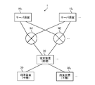
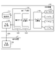
- FIG. 1 is a diagram showing an outline of the present embodiment.
- the tethering master unit in the example of FIG. 1 can use two communication paths, for example, cellular and Wi-Fi.
- the tethering master unit notifies the tethering slave unit of the prediction in advance when the disconnection of the current communication path to the upstream network (including switching of the upstream network) is predicted. (“Disconnection notice” shown in FIG. 1). Further, when the deterioration of the communication path quality to the upstream network is predicted, the tethering master unit notifies the tethering slave unit of the prediction (“quality non-delivery notification” shown in FIG. 1). Then, the tethering slave unit makes a request to the tethering master unit to suppress the change of the communication path to the upstream network (“request” shown in FIG. 1). In addition, the tethering slave unit takes over the flow so that it can communicate using another communication path, or forms a link aggregation to safely terminate the current flow.
- FIG. 2 is a diagram showing a processing flow when a disconnection of a communication path to an upstream network is predicted.
- the tethering master unit and the tethering slave unit generate a path for determining a route between the tethering master unit and the tethering slave unit.
- the tethering master unit preferentially allocates a communication path desired by the tethering slave unit using this path. For example, consider a case where the tethering master unit predicts that Wi-Fi will be disconnected. If it is found that the tethering master unit may disconnect within n seconds of disconnection, the tethering slave unit is notified of a "disconnection notice".
- the tethering slave unit Upon receiving this notification, the tethering slave unit anticipates that the flow during communication will be interrupted, and attempts to safely terminate the flow and hand over to a new bearer. Since there is time for the actual disconnection from the disconnection notice, it is possible for the tethering slave unit to safely suspend and resume communication.
- FIG. 3 is a diagram showing a processing flow when deterioration of the quality of the communication path to the upstream network is predicted.
- the tethering master unit and the tethering slave unit generate a path for determining a route between the tethering master unit and the tethering slave unit. Then, the tethering slave unit uses this path to specify the communication path characteristic to the tethering master unit. For example, the tethering slave unit notifies the tethering master unit of the desired communication path quality (for example, maximum allowable delay, throughput, packet loss rate).
- desired communication path quality for example, maximum allowable delay, throughput, packet loss rate
- the tethering master unit selects a communication path so as to satisfy this communication path quality. Further, the tethering master unit does not switch the communication path because the communication path may be disconnected by the handover even if a path with good communication path quality is found.
- the tethering master unit monitors the packet counter of the communication path and predicts the communication path quality at the current time and the communication path quality after n seconds. Using this result, the tethering master unit automatically switches the upstream network when the communication path quality specified by the tethering slave unit cannot be satisfied. Alternatively, the tethering master unit notifies the tethering slave unit that the quality has not been reached. More specifically, the tethering master unit gives a notice to the tethering slave unit that the quality of the current communication path will not achieve the required quality required by the tethering slave unit.
- the tethering slave unit Upon receiving this notification, the tethering slave unit attempts to safely terminate the current flow and hand over to a new bearer. At this time, if the communication path quality cannot be satisfied even with the new bearer, the tethering slave unit adjusts the bandwidth used by the application being used. For the safe termination of the flow, the tethering slave unit inherits the ID of the existing flow so that communication starts from another communication path in the upper layer, and starts signaling with the communication partner server to create a new flow. May be (QUIC). In addition, the tethering slave unit may paste a multipath using multiple bearers (multipath TCP).
- multipath TCP multipath TCP
- the tethering slave unit may be set to perform detour route control when communication is disconnected by using the redundancy technique (VRRP, OSPF, BGP, etc.) in L3. Further, the tethering slave unit may be required to use a redundancy technique (Link Aggregation, etc.) in L2. At the application layer, the tethering slave unit may suspend the running flow so that it can communicate in the middle or close the existing flow socket. As you can see, there are various termination options.
- the tethering master unit may monitor the communication quality of the communication path between the tethering master unit and the tethering slave unit. Then, the tethering master unit may predict the disconnection of the communication path between the tethering master unit and the tethering slave unit. If it is found that the tethering master unit may disconnect within n seconds of disconnection, a disconnection notice may be sent to the tethering slave unit. Upon receiving this notification, the tethering slave unit may anticipate that the flow during communication will be interrupted and attempt to safely terminate the flow and hand over to a new bearer.
- the tethering master unit notifies the tethering slave unit of communication interruption when communication disconnection or deterioration of communication path quality is predicted. Therefore, the tethering slave unit can perform the handover in advance and safely terminate the flow. As a result, the tethering slave unit may end the flow unintentionally and give an error in the application operation (for example, the download fails and you need to download from the beginning again), or the socket remains open. This makes it possible to prevent a situation in which the next communication path cannot be established. Moreover, since the possibility that one of the communication paths is always established increases, highly reliable communication can be realized.
- FIG. 4 is a diagram showing a configuration example of the communication system 1 according to the embodiment of the present disclosure.
- the communication system 1 includes at least a master unit configured to be connectable to a plurality of communication paths and a slave unit connected to an upstream network via the master unit.
- the master unit is, for example, the terminal device 20 shown in FIG. 4, and the slave unit is, for example, the terminal devices 30 1 and 302 shown in FIG .
- the terminal devices 20 and 30 are configured to be tetherable. Then, the terminal device 30 is connected to the upstream network via the terminal device 20 by using the tethering function.
- the upstream network is a higher-level network when viewed from the terminal device 20 which is the master unit.
- the upstream networks are networks N1 and N2.
- the networks N1 and N2 are communication networks such as LAN (Local Area Network), WAN (Wide Area Network), cellular network, fixed telephone network, regional IP (Internet Protocol) network, and the Internet.
- the networks N1 and N2 may include a wired network or a wireless network.
- the networks N1 and N2 may include a core network.
- the core network is, for example, EPC (Evolved Packet Core) or 5GC (5G Core network).
- the network N may be a data network connected to the core network.
- the data network may be a service network of a telecommunications carrier, for example, an IMS (IP Multimedia Subsystem) network.
- the data network may be a private network such as an in-house network.
- the upstream network is a cellular network composed of a radio access network and a core network
- a plurality of core networks may exist as the upstream network.
- different data networks may exist for each core network.
- the terminal device 20 can be connected to the upstream network using a plurality of communication paths.
- at least one of the plurality of communication paths may be a wireless communication path.
- the communication path may be a wireless communication path (radio access network) between the terminal device 20 and the base station.
- the communication path may be a wireless communication path between the terminal device 20 and the access point.
- the plurality of communication paths may include a wired communication path (for example, a wired LAN).
- the communication path may be the upstream network itself.
- the terminal device 20 uses a wireless access technology (RAT: Radio) such as LTE (Long Term Evolution), NR (New Radio), Wi-Fi, Bluetooth (registered trademark), etc. It may be configured to connect to the upstream network using Access Technology).
- RAT wireless access technology
- the terminal device 20 may be configured to enable different wireless access techniques.
- the terminal device 20 may be configured to enable NR and Wi-Fi.
- the terminal device 20 may be configured to enable the use of different cellular communication techniques (eg, LTE and NR).
- LTE and NR are a kind of cellular communication technology, and enable mobile communication of a terminal device by arranging a plurality of areas covered by a base station in a cell shape.
- LTE includes LTE-A (LTE-Advanced), LTE-A Pro (LTE-Advanced Pro), and EUTRA (Evolved Universal Terrestrial Radio Access).
- NR shall include NLAT (New Radio Access Technology) and FEUTRA (Further EUTRA).
- a single base station may manage a plurality of cells.
- the cell corresponding to LTE is referred to as an LTE cell
- the cell corresponding to NR is referred to as an NR cell.
- NR is a wireless access technology of the next generation (5th generation) of LTE (4th generation communication including LTE-Advanced and LTE-Advanced Pro).
- LTE Long Term Evolution
- NR is a wireless access technology that can support various use cases including eMBB (Enhanced Mobile Broadband), mMTC (Massive Machine Type Communications) and URLLC (Ultra-Reliable and Low Latency Communications).
- eMBB Enhanced Mobile Broadband
- mMTC Massive Machine Type Communications
- URLLC Ultra-Reliable and Low Latency Communications
- the terminal device 20 may be able to connect to the upstream network using a wireless access technique other than LTE, NR, Wi-Fi, and Bluetooth.
- the terminal device 20 may be connectable to an upstream network using LPWA (Low Power Wide Area) communication.
- the terminal device 20 may be able to be connected to the upstream network by using the wireless communication of the original standard.
- LPWA communication is wireless communication that enables wide-range communication with low power consumption.
- the LPWA radio is an IoT (Internet of Things) radio communication using a specific low power radio (for example, 920 MHz band) or an ISM (Industry-Science-Medical) band.
- the LPWA communication used by the terminal device 20 may conform to the LPWA standard.
- LPWA standards include ELTRES, ZETA, SIGFOX, LoRaWAN, NB-IoT and the like.
- the LPWA standard is not limited to these, and other LPWA standards may be used.
- the plurality of communication paths may include a virtual network.
- the plurality of communication paths to which the terminal device 20 can be connected may include a virtual network such as a VLAN (Virtual Local Area Network) and a physical network such as an IP communication path.
- the terminal device 20 may perform route control based on a route control protocol such as OSPF (Open Shortest Path First) or BGP (Border Gateway Protocol).
- OSPF Open Shortest Path First
- BGP Border Gateway Protocol
- the plurality of communication paths may include a plurality of one or a plurality of overlay networks, or may include one or a plurality of network slicing.
- the communication system 1 includes a server device 10, a terminal device 20 (master unit), and a terminal device 30 (slave unit).
- the communication system 1 may include a plurality of server devices 10, terminal devices 20, and terminal devices 30.
- the communication system 1 includes server devices 10 1 , 102 and the like as the server device 10 , and terminal devices 30 1 and 302 and the like as the terminal device 30.
- the device in the figure may be considered as a device in a logical sense.
- some or all of the devices in the figure are realized by virtual machines (VMs: Virtual Machines), containers (Containers), dockers (Docker), etc., and they are implemented on the same physically hardware. May be good.
- VMs Virtual Machines
- Containers Containers
- Docker dockers
- the communication device is a device having a communication function, and in the example of FIG. 4, at least the terminal device 20 and the terminal device 20 are communication devices.
- each device constituting the communication system 1 will be specifically described.
- the configuration of each device shown below is just an example.
- the configuration of each device may be different from the configuration shown below.
- the server device 10 is an information processing device (computer) that provides various services to the terminal device 30 via an upstream network (for example, networks N1 and N2).
- the server device 10 is an application server or a Web server.
- the server device 10 may be a PC server, a midrange server, or a mainframe server.
- FIG. 5 is a diagram showing a configuration example of the server device 10 according to the embodiment of the present disclosure.
- the server device 10 includes a storage unit 11, a communication unit 12, and a control unit 13.
- the configuration shown in FIG. 5 is a functional configuration, and the hardware configuration may be different from this. Further, the functions of the server device 10 may be distributed and implemented in a plurality of physically separated configurations.
- the server device 10 may be composed of a plurality of information processing devices.
- the storage unit 11 is a storage device capable of reading and writing data such as DRAM (Dynamic Random Access Memory), SRAM (Static Random Access Memory), flash memory, and hard disk.
- the storage unit 11 functions as a storage means for the server device 10.
- the storage unit 11 stores, for example, various data for providing services to the terminal devices 20 and 30.
- the communication unit 12 is a communication interface for communicating with other devices.
- the communication unit 12 is a network interface.
- the communication unit 12 is a LAN (Local Area Network) interface such as a NIC (Network Interface Card).
- the communication unit 12 may be a wired interface or a wireless interface.
- the communication unit 12 functions as a communication means of the server device 10.
- the communication unit 12 communicates with the terminal devices 20 and 30 according to the control of the control unit 13.
- the control unit 13 is a controller that controls each unit of the server device 10.
- the control unit 13 is realized by, for example, a processor such as a CPU (Central Processing Unit) or an MPU (Micro Processing Unit).
- the control unit 13 is realized by the processor executing various programs stored in the storage device inside the server device 10 using a RAM (Random Access Memory) or the like as a work area.
- the control unit 13 may be realized by an integrated circuit such as an ASIC (Application Specific Integrated Circuit) or an FPGA (Field Programmable Gate Array).
- the CPU, MPU, ASIC, and FPGA can all be regarded as controllers.
- the terminal device 20 is a communication device that communicates with other communication devices such as a base station, an access point, and a terminal device 30.
- the terminal device 20 has a tethering function (tethering host function) and relays the terminal device 30 to access the upstream network.
- the terminal device 20 is, for example, a mobile phone, a smart device (smartphone or tablet), a PDA (Personal Digital Assistant), or a personal computer. Further, the terminal device 20 may be an image pickup device (for example, a camcorder) equipped with a communication function, or a motorcycle, a mobile relay vehicle, or the like equipped with a communication device such as an FPU (Field Pickup Unit). May be good. Further, the terminal device 20 may be an M2M (Machine to Machine) device or an IoT (Internet of Things) device. The terminal device 20 may be a router having a plurality of communication paths.
- the terminal device 20 may be capable of LPWA communication with other communication devices (for example, a base station, an access point, and a terminal device 30). Further, the wireless communication used by the terminal device 20 may be wireless communication using millimeter waves. The wireless communication used by the terminal device 20 may be wireless communication using radio waves or wireless communication (optical radio) using infrared rays or visible light.
- the terminal device 20 may be a mobile device.
- the mobile device is a mobile wireless communication device.
- the terminal device 20 may be a wireless communication device installed on the mobile body or may be the mobile body itself.
- the terminal device 20 may be a vehicle (Vehicle) moving on the road such as an automobile, a bus, a truck, or a motorcycle, or a wireless communication device mounted on the vehicle.
- the moving body may be a mobile terminal, or may be a moving body that moves on land, in the ground, on the water, or in the water.
- the moving body may be a moving body that moves in the atmosphere such as a drone or a helicopter, or may be a moving body that moves outside the atmosphere such as an artificial satellite.
- the terminal device 20 may be connected to a plurality of base stations or a plurality of cells at the same time to perform communication. For example, when one base station supports a communication area via a plurality of cells (for example, pCell, sCell), carrier aggregation (CA: Carrier Aggregation) technology or dual connectivity (DC: Dual Connectivity) technology, By the multi-connectivity (MC) technology, it is possible to bundle the plurality of cells and communicate with the base station and the terminal device 20. Alternatively, it is also possible for the terminal device 20 and the plurality of base stations to communicate with each other by the coordinated transmission / reception (CoMP: Coordinated Multi-Point Transmission and Reception) technology via the cells of different base stations.
- CoMP Coordinated Multi-Point Transmission and Reception
- FIG. 6 is a diagram showing a configuration example of the terminal device 20 (master unit) according to the embodiment of the present disclosure.
- the terminal device 20 includes a storage unit 21, a communication unit 22, a control unit 23, a sensor unit 24, and a plurality of communication units 25 (communication units 25 1 to 25 n : n are arbitrary integers).
- the configuration shown in FIG. 6 is a functional configuration, and the hardware configuration may be different from this. Further, the functions of the terminal device 20 may be distributed and implemented in a plurality of physically separated configurations.
- the storage unit 21 is a storage device that can read and write data such as DRAM, SRAM, flash memory, and hard disk.
- the storage unit 21 functions as a storage means for the terminal device 20.
- the storage unit 21 stores, for example, the route database 211.
- the route database 211 is, for example, a database that stores routes to the server device 10.
- the route database 211 is a routing table.
- the communication unit 22 is a communication interface for communicating with another device located downstream (for example, a slave unit such as a terminal device 30).
- the communication unit 22 is a network interface.
- the communication unit 22 is a LAN interface such as a NIC.
- the communication unit 22 may be a wired interface or a wireless interface.
- the communication unit 22 functions as a communication means of the terminal device 20.
- the communication unit 22 communicates with the terminal device 30 under the control of the control unit 23.
- the communication unit 22 has a communication interface with the device (that is, the slave unit) located downstream, but the communication unit 22 may have the same configuration as the communication unit 25.
- the control unit 23 is a controller that controls each unit of the terminal device 20.
- the control unit 23 is realized by, for example, a processor such as a CPU or MPU.
- the control unit 23 is realized by the processor executing various programs stored in the storage device inside the terminal device 20 with the RAM or the like as a work area.
- the control unit 23 may be realized by an integrated circuit such as an ASIC or FPGA.
- the CPU, MPU, ASIC, and FPGA can all be regarded as controllers.
- the control unit 33 may be realized by the GPU in addition to or instead of the CPU.
- the control unit 23 includes a parameter collection unit 231, a quality prediction unit 232, a route determination unit 233, a prediction notification unit 234, and an instruction reception unit 235.
- Each block (parameter collecting unit 231 to instruction receiving unit 235) constituting the control unit 23 is a functional block indicating the function of the control unit 23, respectively.
- These functional blocks may be software blocks or hardware blocks.
- each of the above-mentioned functional blocks may be one software module realized by software (including a microprogram), or may be one circuit block on a semiconductor chip (die).
- each functional block may be one processor or one integrated circuit.
- the control unit 23 may be configured in a functional unit different from the above-mentioned functional block. The method of configuring the functional block is arbitrary.
- the sensor unit 24 is a sensor that acquires various information for predicting the quality of the communication path (communication path formed by the communication unit 25) for connecting to the upstream network.
- the sensor unit 24 is a sensor that detects, for example, the reception S / N of radio waves received from a base station or an access point.
- the information acquired by the sensor unit 24 is not limited to the receiving S / N as long as it can be used for quality prediction of the communication path.
- Each of the plurality of communication units 25 is a communication interface for connecting to the upstream network.
- Each of the plurality of communication units 25 forms different communication paths up to the server device 10.
- the plurality of communication units 25 may each support different wireless access techniques.
- the communication unit 251 may correspond to LTE or NR, and the communication unit 252 may correspond to Wi-Fi.
- the communication unit 25 may have the same configuration as the communication unit 22.
- the terminal device 30 is a communication device that communicates with other communication devices such as the terminal device 20.
- the terminal device 30 has a tethering function (tethering client function) and accesses the upstream network via the terminal device 20.
- the terminal device 30 may have a function of directly accessing the upstream network without going through the terminal device 20.
- the terminal device 30 may be directly accessible to the base station or access point.
- the terminal device 30 is, for example, a mobile phone, a smart device (smartphone or tablet), a PDA, or a personal computer. Further, the terminal device 30 may be an image pickup device (for example, a camcorder) equipped with a communication function, or may be a motorcycle, a mobile relay vehicle, or the like equipped with a communication device such as an FPU. Further, the terminal device 30 may be an M2M device or an IoT device. The terminal device 30 may be a router.
- the terminal device 30 may be capable of LPWA communication with another communication device (for example, the terminal device 20). Further, the wireless communication used by the terminal device 30 may be wireless communication using millimeter waves. The wireless communication used by the terminal device 30 may be wireless communication using radio waves or wireless communication (optical radio) using infrared rays or visible light.
- the terminal device 30 may be a mobile device.
- the mobile device is a mobile wireless communication device.
- the terminal device 30 may be a wireless communication device installed on the mobile body or may be the mobile body itself.
- the terminal device 30 may be a vehicle (Vehicle) moving on the road such as an automobile, a bus, a truck, or a motorcycle, or a wireless communication device mounted on the vehicle.
- the moving body may be a mobile terminal, or may be a moving body that moves on land, in the ground, on the water, or in the water.
- the moving body may be a moving body that moves in the atmosphere such as a drone or a helicopter, or may be a moving body that moves outside the atmosphere such as an artificial satellite.
- FIG. 7 is a diagram showing a configuration example of the terminal device 30 (slave unit) according to the embodiment of the present disclosure.
- the terminal device 30 includes a storage unit 31, a communication unit 32, and a control unit 33.
- the configuration shown in FIG. 7 is a functional configuration, and the hardware configuration may be different from this. Further, the functions of the terminal device 30 may be distributed and implemented in a plurality of physically separated configurations.
- the storage unit 31 is a storage device that can read and write data such as DRAM, SRAM, flash memory, and hard disk.
- the storage unit 31 functions as a storage means for the terminal device 30.
- the storage unit 31 stores, for example, the route database 311.
- the route database 311 is, for example, a database that stores routes to the server device 10.
- the route database 311 is a routing table.
- the communication unit 32 is a communication interface for communicating with other devices such as the terminal device 30.
- the communication unit 32 is a network interface.
- the communication unit 32 is a LAN interface such as a NIC.
- the communication unit 32 may be a wired interface or a wireless interface.
- the communication unit 32 functions as a communication means of the server device 10.
- the communication unit 32 communicates with the terminal device 30 under the control of the control unit 33.
- the control unit 33 is a controller that controls each unit of the terminal device 30.
- the control unit 33 is realized by, for example, a processor such as a CPU or MPU.
- the control unit 33 is realized by the processor executing various programs stored in the storage device inside the terminal device 30 with the RAM or the like as a work area.
- the control unit 33 may be realized by an integrated circuit such as an ASIC or FPGA.
- the CPU, MPU, ASIC, and FPGA can all be regarded as controllers. Further, the control unit 33 may be realized by the GPU in addition to or instead of the CPU.
- the control unit 33 includes an application processing unit 331, a session management unit 332, a route determination unit 333, a prediction reception unit 334, and an instruction transmission unit 335.
- Each block (application processing unit 331 to instruction transmission unit 335) constituting the control unit 33 is a functional block indicating the function of the control unit 33, respectively.
- These functional blocks may be software blocks or hardware blocks.
- each of the above-mentioned functional blocks may be one software module realized by software (including a microprogram), or may be one circuit block on a semiconductor chip (die).
- each functional block may be one processor or one integrated circuit.
- the control unit 33 may be configured in a functional unit different from the above-mentioned functional block. The method of configuring the functional block is arbitrary.
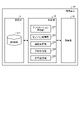
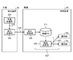
- FIG. 8 is a diagram showing a functional configuration of the communication system 1. More specifically, FIG. 8 is a diagram showing the relationship between the terminal device 20 and the functional blocks constituting the terminal device 30.
- the white arrows indicate the flow of data sent and received via the upstream network, such as user data.
- Other arrows indicate the flow of control data related to the switching process of the present embodiment.
- the parameter collection unit 231 and the quality prediction unit 232 function as prediction means (prediction unit) of the terminal device 20.
- the route determination unit 233 and the instruction reception unit 235 function as communication control means (communication control unit) of the terminal device 20.
- the prediction notification unit 234 functions as a notification means (notification unit) of the terminal device 20.
- the application processing unit 331, the session management unit 332, and the route determination unit 333 function as processing means (processing unit) of the terminal device 20.
- the predictive receiving unit 334 functions as a receiving means (receiving unit) of the terminal device 20.
- the instruction transmission unit 335 functions as an instruction means (instruction unit) of the terminal device 20.
- the first processing example is a processing example in which the terminal device 20 (master unit) predicts (including switching) the disconnection of the current communication path to the upstream network.
- the terminal device 20 (master unit) is connected to the upstream network by one of a plurality of communication paths.
- the terminal device 20 (master unit) makes a prediction regarding disconnection of the communication path (including switching to another communication path), and notifies the terminal device 30 (slave unit) of the prediction result.
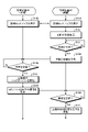
- FIG. 9 is a flowchart showing a first processing example (prediction of disconnection of a communication path to an upstream network).
- the first processing example will be described with reference to FIG.
- the terminal device 20 and the terminal device 30 execute the initial setup (steps S11A, S11B).
- the initial setup is a process for the terminal device 20 and the terminal device 30 to create a control path.
- the control path is a path for exchanging various information related to the prediction of disconnection of the communication path.
- the control path between the terminal device 20 (master unit) and the terminal device 30 (slave unit) may be created when the network between the master unit and the slave unit is formed. Further, if the function related to the prediction notification is enabled after the normal tethering function is enabled, the control path may be created at that time. This control path does not require much communication. On the other hand, it requires a highly reliable communication path. Therefore, it is desirable that the bearer used is a stable bearer (for example, a wired LAN) different from the bearer used for data transfer between the master unit and the slave unit (for example, a wireless LAN).
- FIG. 10 is a sequence diagram showing the initial setup.
- the terminal device 30 (slave unit) opens a standby port so that communication can be performed between the master unit and the slave unit.
- the terminal device 20 (master unit) sends a standby completion notification to the opened port using the control path (step S111).
- the terminal device 30 (slave unit) transmits a control path connection request to the terminal device 20 (step S112).
- the terminal device 20 that has received the control path connection request performs the control path establishment process.
- the terminal device 20 and the terminal device 30 may exchange information regarding disconnection prediction in the initial setup. For example, it is assumed that the terminal device 20 predicts, as a prediction process, whether communication using the current communication path will be disconnected after a lapse of a predetermined time. In this case, the terminal device 30 may notify the terminal device 30 of information specifying a predetermined time in the initial setup.
- the terminal device 20 then starts the prediction process of disconnecting the current communication path to the upstream network (step S12). For example, the terminal device 20 starts a process of predicting whether communication with the upstream network using the current communication path will be disconnected after a lapse of a predetermined time.
- the predetermined time may be a predetermined time set in the terminal device 20 and the terminal device 30 and shared by the terminal device 20 and the terminal device 30. Further, the predetermined time may be the time specified by the terminal device 30 for the terminal device 20 in the initial setup.
- the terminal device 20 continues the prediction process until the disconnection is predicted.
- the terminal device 20 notifies the terminal device 30 of information regarding the current communication path (step S14A).
- the information about the communication path is, for example, information for predicting that the communication with the upstream network using the current communication path will be disconnected after a lapse of a predetermined time.
- the notification of the disconnection prediction by the terminal device 20 may be referred to as a disconnection notice.
- the terminal device 30 determines whether or not the disconnection notice has been received from the terminal device 20 (step S14B). If the disconnection notice has not been received (step S14B: No), the terminal device 30 repeats step S14B until the disconnection notice is received.
- the terminal device 30 starts the handover process (step S15).
- the handover process is a process for changing the current bearer via the terminal device 20 to a new bearer.
- the terminal device 30 requests the terminal device 20 to switch the communication path to the upstream network.
- the terminal device 30 may request the terminal device 20 to switch the upstream network (step S16A).
- the terminal device 30 requests the terminal device 20 to switch the upstream network to network N2.
- the terminal device 30 may request that the communication path be switched from the wireless access network for cellular communication to Wi-Fi, or from Wi-Fi to the wireless access network for cellular communication. It is also possible to regard the upstream network as a wireless access network for cellular communication or Wi-Fi.
- the terminal device 30 may perform processing related to a predetermined function when receiving the disconnection notice.
- the predetermined function may be, for example, application processing performed by the application processing unit 331.
- the terminal device 30 may perform an application stop process as a process related to a predetermined function. By stopping the application before disconnecting, it is possible to prevent the execution of the application from falling into an error.
- the terminal device 30 may perform a process of switching the upstream network currently used by the application processing unit 331 to another upstream network as a process related to a predetermined function. For example, the terminal device 30 requests the terminal device 20 to switch the upstream network (for example, network N1) currently used by the application processing unit 331 to another upstream network (for example, network N2). You may. By switching the upstream network before disconnection, it is possible to prevent the execution of the application from falling into an error.
- the terminal device 20 determines whether or not a request has been received from the terminal device 30 (step S16B). For example, the terminal device 20 determines whether or not a request for switching the upstream network has been received from the terminal device 30. If the request has not been received from the terminal device 30 (step S16B: No), the terminal device 20 repeats step 16B until the request is received from the terminal device 30. When the request is received from the terminal device 30 (step S16B: Yes), the terminal device 20 executes the process related to the request. For example, if the request received from the terminal device 30 is an upstream network switching request, the terminal device 20 executes the upstream network switching process (step S17).
- the terminal device 20 and the terminal device 30 repeat the processing (steps S12 to S17) after the initial setup.
- the terminal device 30 since the terminal device 30 receives the information related to the disconnection in advance before the communication path is disconnected, the terminal device 30 can perform processing such as stopping the application or performing a handover before disconnecting. Become. As a result, the terminal device 30 can reliably communicate with the connection even if it is connected to the upstream network via the terminal device 20.
- the second processing example is a processing example in which the terminal device 20 (master unit) predicts the quality of the current communication path to the upstream network.
- the terminal device 20 (master unit) is connected to the upstream network by one of a plurality of communication paths.
- the terminal device 20 (master unit) makes a prediction regarding the quality of the communication path, and notifies the terminal device 30 (slave unit) of the prediction result.
- FIG. 11 is a flowchart showing a second processing example (quality prediction of the communication path to the upstream network).
- a second processing example will be described with reference to FIG.
- the terminal device 20 and the terminal device 30 execute the initial setup (steps S21A and S21B).
- the initial setup is a process for the terminal device 20 and the terminal device 30 to create a control path.
- the control path is a process for creating a path for exchanging various information related to quality prediction of a communication path.
- the control path between the terminal device 20 (master unit) and the terminal device 30 (slave unit) may be created when the network between the master unit and the slave unit is formed. Further, if the function related to the prediction notification is enabled after the normal tethering function is enabled, the control path may be created at that time. This control path does not require much communication. On the other hand, it requires a highly reliable communication path. Therefore, it is desirable that the bearer used is a stable bearer (for example, a wired LAN) different from the bearer used for data transfer between the master unit and the slave unit (for example, a wireless LAN).
- FIG. 12 is a sequence diagram showing the initial setup.
- the terminal device 30 (slave unit) opens a standby port so that communication can be performed between the master unit and the slave unit.
- the terminal device 20 (master unit) sends a standby completion notification to the opened port using the control path (step S111).
- the terminal device 30 Upon receiving the standby completion notification from the terminal device 20, the terminal device 30 transmits the control path connection request to the terminal device 20 (step S112).
- the terminal device 20 that has received the control path connection request performs the control path establishment process.
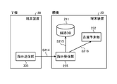
- FIG. 13 is a functional block diagram for explaining the initial setup.
- the instruction transmission unit 335 of the terminal device 30 sends the information of the notification standard of the information regarding the current communication path of the upstream network to the terminal device 20 using the control path.
- the instruction transmission unit 335 of the terminal device 30 may send the required quality information, which is the quality of the communication path required by another communication device, to the terminal device 20 as the information of the notification standard (step S214).
- the required quality information is, for example, information that a throughput of at least 10 Mbps is desired, information indicating that a response from a specific host is performed within 100 ms, and / or a packet loss rate of less than 0.1%. Information, which indicates.
- the information of the notification standard may include the information of the specified time in addition to the information of the required quality.
- the information at the designated time is information for designating how long before the terminal device 20 notifies the terminal device 30 when it is predicted that the quality of the communication path will not satisfy the required quality.
- the terminal device 30 specifies that it wants to receive a notification from the terminal device 20 10 seconds before the required quality is not satisfied by the information of the designated time.
- the file format of the notification standard information may be in any form.
- the notification standard information may be described in json format, YAML format, or protocol buffer format.
- the notification standard information may be described in a file format as shown in FIG.
- FIG. 14 is a diagram for explaining a file format of information of the notification standard.
- the notification standard can be set for each application or each flow. For example, when there are a plurality of applications operating on the terminal device 30 and there are a plurality of communication path required characteristics, the required quality is set for each application in order to realize the respective communication path characteristics.
- the application (or flow) may be identifiable by adding a descriptor (for example, “port”: “23”) that identifies the port number to the notification standard shown in FIG.
- the terminal device 20 registers the information of the notification standard sent from the terminal device 30 (steps S215 and S216). Specifically, the instruction receiving unit 235 of the terminal device 20 registers the required quality information included in the notification standard information in the route database 211 (step S215). For example, the instruction receiving unit 235 analyzes the required quality information sent from the terminal device 30. Then, the instruction receiving unit 235 writes a routing rule in the route database 211 based on the analysis result. For example, if the required quality information is information that requires a minimum throughput of 10 Mbps, a communication path that satisfies the required quality (for example, a wireless access network for cellular communication) is set to be a communication path to the upstream network.
- the required quality information is information that requires a minimum throughput of 10 Mbps
- a communication path that satisfies the required quality for example, a wireless access network for cellular communication
- the communication path to be set may be the default route of the master unit itself (terminal device 30 itself).
- the terminal device 20 does not use the default route.
- a bearer that is expected to have a constant throughput may be set in the communication path.
- the terminal device 20 may define a route for each application or each flow.
- An SDN protocol such as OpenFlow can be considered as a method for realizing this, but the terminal device 20 may use another method.
- the terminal device 20 may set up a virtual router and write a routing rule in each of them.
- the instruction receiving unit 235 of the terminal device 20 registers the information regarding the notification of the quality prediction (information of the notification standard) in the quality prediction unit 232. More specifically, the instruction receiving unit 235 registers the required quality information and the designated time information included in the notification standard information in the quality prediction unit 232 (step S216). When an event that satisfies the registered notification criteria occurs (that is, when the communication path quality is not achieved), the quality prediction unit 232 notifies the prediction notification unit 234. The processing of the quality prediction unit 232 will be described in detail later.
- the terminal device 20 starts the process of predicting the quality of the current communication path to the upstream network (step S22).
- the quality prediction unit 232 of the terminal device 20 predicts the communication path quality by using the communication parameters of the upstream network and the information from the sensor unit 24 and the external sensor.
- the quality prediction unit 232 may predict that a predetermined parameter (for example, throughput, delay, packet loss rate) representing the communication path quality exceeds a predetermined threshold value.
- the quality prediction unit 232 may predict that the bearer will become unusable (for example, the Wi-Fi connection will be disconnected from the access point, or the cellular communication will become unusable).
- the switching may be labeled. The following (1) to (4) can be assumed as the deterioration event of UX.
- the terminal device 20 combines a plurality of sensors (for example, an in-camera, a depth sensor, and a 3D sensor) mounted on the terminal device 20 or the terminal device 30 to make the user uncomfortable with the communication quality (that is, deterioration of UX). May be detected. Further, the terminal device 20 may detect the discomfort with respect to the communication quality of the user by detecting the operation performed when the user feels discomfort. When the user feels uncomfortable, the operation is that the user presses a predetermined button, a predetermined icon, or a predetermined hardware button displayed on the screen of the terminal device 30, or shakes the terminal device 30 having a predetermined pattern. Operation is expected.
- sensors for example, an in-camera, a depth sensor, and a 3D sensor
- the quality prediction unit 232 may predict the communication path quality by using machine learning, or may predict the communication path quality by using a model represented by a linear equation.
- the quality prediction unit 232 may be configured by a learning model for predicting the channel quality.
- the learning model may be a neural network model obtained by machine learning (including deep learning).
- the neural network model is composed of a plurality of layers called an input layer, a hidden layer (also referred to as an intermediate layer), and an output layer. Each of these plurality of layers is composed of one or a plurality of nodes. These multiple nodes are connected via an edge. Each layer has a function called the activation function, and each edge is weighted.
- the neural network model may be, for example, a model in a form called CNN (Convolution Neural Network), RNN (Recurrent Neural Network), or LSTM (Long Short-Term Memory).
- CNN Convolution Neural Network
- RNN Recurrent Neural Network
- LSTM Long Short-Term Memory
- the learning model may be composed of a plurality of neural network models.
- the learning model may be composed of a plurality of neural network models selected from, for example, CNN, RNN, and LSTM.
- the training model is composed of a plurality of neural network models, the plurality of neural network models are processed depending on or in parallel.
- the learning model is not limited to the model by deep learning.
- the learning model may be a model by reinforcement learning.
- reinforcement learning actions (settings) that maximize value through trial and error are learned.
- the information processing device (hereinafter referred to as a learning device) that performs learning may be a terminal device 30 or another device (for example, a server device 10 or a terminal device 30).
- the learning device assigns a correct answer label (for example, 1) to a place where an object to be predicted (for example, a throughput becomes n Mbps or less) occurs, assigns 0 to other places, and learns time series data.
- You may generate a predictor (learning model).
- the learning device can generate a predictor (learning model) that predicts n seconds before the event occurs by assigning the correct answer label 1 from n seconds before the event occurs.
- the following (1) to (3) can be assumed as the parameters used for learning.
- learning parameters As the parameters used for learning (hereinafter referred to as learning parameters), all the parameters shown below may be used, or some parameters shown below may be used.
- Wi-Fi parameters can be assumed as parameters used for learning. Specific examples of Wi-Fi parameters are listed below.
- PHY protocol type (a / b / g / n / ac / ax), MAC protocol type (d / e / h / i / j / k / p / v / w / y / z), signal strength (RSSI: Received) Signal Strength Indicator), frequency used, SSID (Service Set Identifier), BSSID (Basic Service Set Identifier), allocated bandwidth, RTT of radio section to access point, S / N ratio, frequency spectrum, same BSS (Basic Service Set) Number of terminals inside, authentication method, number of MIMO (Multi Input Multi Output) layers, number of signal collisions, number of RTS / CTS (Request to Send / Clear to Send) per unit time, number of probe requests, number of beacons received, Received / transmitted packet counter value, number of successful transmissions, number of successful receptions, number of transmission retransmissions, number of frame corruptions, number of interface errors
- Cellular communication parameters can be assumed as parameters used for learning. Specific examples of cellular communication parameters are listed below.
- MCS Modulation and Coding Scheme
- capability LTE / HSPA + / GSM (registered trademark)
- signal strength number of MIMO layers, number of communication allocation hours, actual number of resource blocks, received / transmitted packets
- Counter value number of successful transmissions, number of successful receptions, number of frame retransmissions (MAC), number of RLC (Radio Link Control), number of interface errors, throughput (PHY / IP), cell information (cell ID, transmission of downlink reference signal) Power, adjacent cell information, cell capacity, backbone bandwidth information), contract plan, contract communication capacity, remaining communication capacity, speed limit application status
- Sensor parameters can be assumed as parameters used for learning. Specific examples of sensor parameters are listed below.
- -Sensor information that can be used to estimate the user's position and movement speed, such as acceleration, magnetism, direction, pressure, and position sensor.
- -To infer user behavior such as acceleration, time, direction, pressure, position, and number of steps.
- Sensor information that can be used, or behavior information that can be inferred from them (walking, train, moving by car, climbing up and down stairs, climbing up and down by elevator, etc.)
- -Camera blood pressure information
- application information necessary to measure the user's situation such as acceleration, magnetism, direction, pressure, and position sensor.
- FIG. 15 is a functional block diagram for explaining quality prediction using machine learning. Hereinafter, a specific operation example of quality prediction using machine learning will be described.
- the quality prediction unit 232 of the terminal device 20 includes a score calculation unit and a determination unit.
- the score calculation unit is composed of a learning model learned by the above-mentioned learning parameters.
- the score calculation unit is configured to output the communication path quality score of each of the plurality of bearers.
- Each of the plurality of bearers corresponds to a communication path in which the terminal device 30 can be used.
- the quality prediction unit 232 inputs the parameters collected by the parameter collection unit 231 into the score calculation unit. Then, the quality prediction unit 232 calculates the quality score of each bearer using the learning model.
- the quality prediction unit 232 may be configured to use the data detected by the sensor as input data to the score calculation unit.
- the quality prediction unit 232 is configured to input the data detected by the sensor unit 24 of the terminal device 20 to the score calculation unit, but an external sensor (for example, the terminal device 30).
- the sensor may be configured to input the detected data.
- the quality prediction unit 232 may be configured to use the acceleration information detected by the acceleration sensor of the terminal device 30 as input data to the score calculation unit.
- the quality prediction unit 232 may be configured to use the amount of change in the position information detected by the position sensor (for example, GPS sensor) of the terminal device 30 for a certain period of time as input data to the score calculation unit.
- the quality prediction unit 232 can predict that the performance of Wi-Fi will deteriorate after a few seconds based on the moving speed and the acceleration state of the user.
- the sensor value may be used as an input parameter of the neural network, or may be used in other ways. For example, when using an elevator, it is expected that the environment for both cellular communication (LTE / NR) and Wi-Fi will deteriorate. In this case, the terminal device 20 may notify the terminal device 20 that stable communication cannot be performed regardless of which bearer is used.
- LTE / NR cellular communication
- Wi-Fi Wi-Fi
- the senor may be a sensor mounted inside the terminal device 20 or an external sensor (for example, a sensor mounted on the terminal device 20 or another device).
- the sensor may be a sensor mounted on a device that can be used as an activity meter.
- a device that can be used as an activity meter a device that is worn and used by a user, such as a smart watch or a pedometer, is assumed.
- the terminal device 20 can grasp the state of the user used for the prediction with higher accuracy by using the pulse information, the number of steps, the acceleration, and the like. It is also conceivable to estimate the user's stress state from the sensor value and change the switching characteristics accordingly. For example, when frustrated, the switching threshold may be adjusted to make it easier to select a faster bearer.
- the interface to be connected may be USB (Universal Serial Bus), Bluetooth (registered trademark), etc., but may be connected via other interfaces. Further, a plurality of these predictors (learning models) may be installed for each event to be predicted.
- the terminal device 20 determines whether or not the quality of the current communication path has not reached after the lapse of the designated time. That is, the terminal device 20 determines whether the quality of the current communication path does not achieve the required quality of the terminal device 30 after the lapse of the designated time of the terminal device 30 (step S23).
- the terminal device 20 may be determined as follows.
- the quality prediction unit 232 of the terminal device 20 includes a score calculation unit and a determination unit as shown in FIG. Then, the score calculation unit shall output a score indicating the communication path quality of each bearer.
- Each bearer corresponds to each communication path in which the terminal device 20 can be used.
- the determination unit compares the current bearer score among the plurality of scores output by the score calculation unit with the threshold value set in the terminal device 30. Then, the determination unit may determine whether the quality of the current communication path does not achieve the required quality after the lapse of the specified time, based on whether the score exceeds the threshold value.
- the determination target of the judgment unit does not necessarily have to be "whether the quality of the current communication path does not achieve the required quality after the lapse of the specified time". For example, when the required quality of the terminal device 30 is set to a quality with a margin in advance, the determination target of the determination unit is "whether the quality of the current communication path currently achieves the required quality”. May be good.
- the threshold value varies depending on the required quality information notified from the terminal device 20.
- the information of the required quality from the terminal device 30 is the information that specifies the throughput (for example, the information that the information is notified when the throughput becomes 10 Mbps or less).
- the prediction target of the predictor (learning model) and the target related to the required quality of the terminal device 30 are the same.
- the prediction target of the predictor (learning model) has a throughput of 10 Mbps or less
- the required quality of the terminal device 30 is a throughput of 10 Mbps or less.
- the determination unit sets the threshold value to the default threshold value (for example, 0.5).
- the discriminating unit may determine the threshold value by another method. For example, the discriminating unit may use a value determined by the terminal device 20 or the developer of the terminal device 20 by actually investigating the corresponding value as a threshold value.
- the terminal device 20 continues the prediction process until the quality is predicted to be unachieved.
- the prediction notification unit 234 of the terminal device 20 sends information about the current communication path to the terminal device 30 at the timing when the prediction is made. Notify (step S24A).
- the information regarding the communication path may be, for example, information for notifying the terminal device 30 of the non-delivery of the communication path quality (hereinafter, referred to as a quality non-delivery notice).
- the judgment target of the judgment unit is "whether the current quality of the communication path does not currently achieve the required quality"
- the quality of the communication path satisfies the required quality at the "timing when the prediction is made”. It will be the timing when it disappears.
- the information about the current communication path may include information to change the communication path related to the control path. good.
- the predictive receiving unit 334 of the terminal device 30 determines whether or not the quality non-delivery notice has been received from the terminal device 20 (step S24B). When the quality non-delivery notice has not been received (step S24B: No), the prediction receiving unit 334 repeats step S24B until the quality non-delivery notice is received.
- the terminal device 30 starts the handover process (step S25).
- the handover process is a process for changing the current bearer via the terminal device 20 to a new bearer.
- the terminal device 30 requests the terminal device 20 to switch the communication path to the upstream network. If the upstream network is regarded as one communication path, the terminal device 30 may request the terminal device 20 to switch the upstream network (step S26A). If the current upstream network is network N1, the terminal device 30 requests the terminal device 20 to switch the upstream network to network N2. Of course, the terminal device 30 may request that the communication path be switched from the wireless access network for cellular communication to Wi-Fi, or from Wi-Fi to the wireless access network for cellular communication. It is also possible to regard the upstream network as a wireless access network for cellular communication or Wi-Fi.
- FIG. 16 is a functional block diagram for explaining the operation of the terminal device 30 (slave unit) when the communication path quality is not achieved.
- the instruction transmission unit 335 of the terminal device 30 specifies a specific flow to be switched, and specifies to the terminal device 20 which bearer to switch to (step S25).
- the file format of the notification according to this designation may be any format.
- the notification relating to this designation may be described in json format, YAML format, or protocol buffer format.
- the terminal device 30 may perform processing related to a predetermined function when receiving the quality non-delivery notice.
- the predetermined function may be, for example, application processing performed by the application processing unit 331.
- the terminal device 30 may perform an application stop process as a process related to a predetermined function. By stopping the application before disconnecting, it is possible to prevent the execution of the application from falling into an error.
- the terminal device 30 may perform a process of switching the upstream network currently used by the application processing unit 331 to another upstream network as a process related to a predetermined function. For example, the terminal device 30 requests the terminal device 20 to switch the upstream network (for example, network N1) currently used by the application processing unit 331 to another upstream network (for example, network N2). You may. By switching the upstream network before disconnection, it is possible to prevent the execution of the application from falling into an error.
- the terminal device 20 determines whether or not a request has been received from the terminal device 30 (step S26B).
- the instruction receiving unit 235 of the terminal device 20 determines whether or not the request regarding the switching of the communication path has been received from the terminal device 30.
- the request for switching the communication path may include a request for the quality of the communication path.
- the channel quality requirement may include quality information that the channel after switching must meet.
- the terminal device 20 repeats step 26B until the request is received from the terminal device 30.
- the terminal device 20 executes the process related to the request. For example, if the request received from the terminal device 30 is a communication path switching request, the terminal device 20 executes the communication path switching process (step S27).
- the instruction receiving unit 235 of the terminal device 20 writes the route information related to the switching in the route database 211 in response to the instruction.
- the request for switching the communication path includes the request for the quality of the communication path
- the instruction receiving unit 235 writes the information of the communication path of the quality satisfying the request to the route database 211.
- the terminal device 20 switches the communication path based on the route information written in the route database 211. As a result, the terminal device 20 switches the current communication path to another communication path that satisfies the required quality of the terminal device 30.
- the communication path switching process performed by the terminal device 20 may include a process of switching a connection using one communication function to a connection in which a plurality of communication functions are bundled.
- FIG. 17 is a functional block diagram for explaining the operation of the terminal device 30 (slave unit) when the communication path quality is not achieved. For example, if the routing unit 233 of the terminal device 20 cannot meet the required quality by using any of the plurality of communication paths in one communication path, the route determination unit 233 uses one communication path to access the upstream network. You may switch to access using LAG (Link Aggregation Group) that bundles multiple communication paths. By using LAG, communication can be made more stable.
- LAG Link Aggregation Group
- the terminal device 30 may adjust the band used by the application being used.
- the terminal device 30 inherits the ID of the existing flow so as to start communication from another communication path in the upper layer, and signals with the communication partner server to create a new flow. May start (QUIC). Further, the terminal device 30 may attach a multipath using a plurality of bearers (multipath TCP). Further, the terminal device 30 may be set to perform detour route control when communication is disconnected by using the redundancy technique (VRRP, OSPF, BGP, etc.) in L3. Further, the terminal device 30 may be required to use a redundancy technique (Link Aggregation or the like) in L2. At the application layer, the tethering slave unit may suspend the running flow so that it can communicate in the middle or close the existing flow socket. Thus various termination options can be recalled.
- multipath TCP multipath TCP
- the terminal device 30 may attach a multipath using a plurality of bearers (multipath TCP). Further, the terminal device 30 may be set to perform detour route control when communication is disconnected by using the redundancy technique (VRRP, OSPF
- the terminal device 30 may be connected to the upstream network by using a bearer different from the bearer related to tethering.
- the terminal device 20 and the terminal device 30 repeat the processing (steps S22 to S27) after the initial setup.
- the terminal device 30 since the terminal device 30 receives the information related to the communication path quality in advance before the deterioration of the communication path quality, the terminal device 30 stops the application or performs a handover before the deterioration of the communication path quality. Etc. can be processed. As a result, the terminal device 30 can reliably communicate with the connection even if it is connected to the upstream network via the terminal device 20.
- the terminal device 20 (master unit) predicts the disconnection of the communication path to the upstream network, but the terminal device 20 (master unit) and the terminal device 30 A prediction may be made regarding the disconnection of the communication path (that is, the downstream network) with the (slave unit). If it is found that the terminal device 20 (master unit) may be disconnected within n seconds, the terminal device 30 (slave unit) may be notified of the disconnection notice. Upon receiving this notification, the terminal device 30 (slave unit) may attempt to safely terminate the flow and hand over to a new bearer in anticipation that the flow during communication will be interrupted.
- the terminal device 20 (master unit) predicts the quality of the communication path to the upstream network, but the terminal device 20 (master unit) and the terminal device 30 You may make a prediction about the quality of the communication path (that is, the downstream network) with (slave unit). If the terminal device 20 finds that the required quality may not be satisfied within n seconds, the terminal device 30 may be notified of the quality non-delivery notice. Upon receiving this notification, the terminal device 30 may anticipate that the flow during communication will be interrupted and attempt to safely terminate the flow and hand over to a new bearer.
- the control device that controls the server device 10, the terminal device 20, and the terminal device 30 of the present embodiment may be realized by a dedicated computer system or a general-purpose computer system.
- a communication program for executing the above operation is stored and distributed in a computer-readable recording medium such as an optical disk, a semiconductor memory, a magnetic tape, or a flexible disk.
- the control device is configured by installing the program on a computer and executing the above-mentioned processing.
- the control device may be an external device (for example, a personal computer) of the server device 10, the terminal device 20, and the terminal device 30.
- the control device may be a device inside the server device 10, the terminal device 20, and the terminal device 30 (for example, the control unit 13, the control unit 23, and the control unit 33).
- the above communication program may be stored in a disk device provided in a server device on a network such as the Internet so that it can be downloaded to a computer or the like.
- the above-mentioned functions may be realized by collaboration between the OS (Operating System) and the application software.
- the part other than the OS may be stored in a medium and distributed, or the part other than the OS may be stored in the server device so that it can be downloaded to a computer or the like.
- each component of each device shown in the figure is a functional concept, and does not necessarily have to be physically configured as shown in the figure. That is, the specific form of distribution / integration of each device is not limited to the one shown in the figure, and all or part of the device is functionally or physically dispersed / physically distributed in arbitrary units according to various loads and usage conditions. Can be integrated and configured. The configuration by this distribution / integration may be performed dynamically.
- the present embodiment includes a device or any configuration constituting the system, for example, a processor as a system LSI (Large Scale Integration) or the like, a module using a plurality of processors, a unit using a plurality of modules, or a unit. It can also be implemented as a set or the like (that is, a part of the configuration of the device) to which other functions are added.
- a processor as a system LSI (Large Scale Integration) or the like, a module using a plurality of processors, a unit using a plurality of modules, or a unit. It can also be implemented as a set or the like (that is, a part of the configuration of the device) to which other functions are added.
- LSI Large Scale Integration
- the system means a set of a plurality of components (devices, modules (parts), etc.), and it does not matter whether all the components are in the same housing. Therefore, a plurality of devices housed in separate housings and connected via a network, and a device in which a plurality of modules are housed in one housing are both systems. ..
- the present embodiment can have a cloud computing configuration in which one function is shared and jointly processed by a plurality of devices via a network.
- the terminal device 20 (master unit) is used with respect to the terminal device 30 (slave unit) when communication disconnection or deterioration of communication path quality is predicted. Notice the communication interruption. Therefore, the terminal device 30 can perform the handover or safely terminate the flow in advance. As a result, the terminal device 30 can prevent a situation in which the flow is unintentionally terminated and an error occurs in the application operation, or the next communication path cannot be established due to the socket being left open. can. Moreover, since the possibility that one of the communication paths is always established increases, highly reliable communication can be realized.
- the present technology can also have the following configurations.
- a communication device having multiple communication functions that connects to an upstream network using different communication paths.
- a communication control unit that controls communication with other communication devices connected to the upstream network via the communication device, and
- a notification unit that notifies the other communication device of information about the communication path for switching the communication path before the switching.
- the communication control unit receives the information of the notification standard of the information regarding the communication path from the other communication device, and receives the information of the notification standard.
- the notification unit notifies the other communication device of information about the communication path based on the notification standard.
- the communication device according to (1) above.
- the information of the notification standard includes information of required quality, which is the quality of the communication path required by the other communication device.
- the notification unit notifies the other communication device of information about the communication path based on the information of the required quality.
- the notification unit notifies the other communication device of information about the communication path at a timing when the quality of the communication path does not satisfy the required quality.
- the notification standard information includes information on a designated time, which is a time designated by the other communication device.
- the notification unit notifies the other communication device of information about the communication path at a timing when it is predicted that the quality of the communication path will not satisfy the required quality after the lapse of the designated time.
- a prediction unit that predicts the communication path is provided.
- the notification unit notifies the other communication device of information about the communication path based on the prediction result of the prediction unit.
- the communication device according to any one of (1) to (5) above.
- the prediction unit predicts that communication with the upstream network using the current communication path will be disconnected after a lapse of a predetermined time. When the disconnection is predicted, the notification unit notifies the other communication device of information about the communication path.
- the communication control unit Upon receiving a request regarding switching of the communication path from the other communication device to which the information regarding the communication path has been notified, Controls the switching of the communication path based on the request from the other communication device.
- the communication device according to any one of (1) to (7) above.
- the request for switching the communication path includes the request for the quality of the communication path.
- the communication control unit When the communication control unit receives the request from the other communication device, the communication control unit switches to a communication path having a quality satisfying the request.
- the control related to the switching of the communication path includes a control for switching a connection using one communication function to a connection in which a plurality of the communication functions are bundled.
- (11) A communication device that can be connected to the upstream network via another communication device having a plurality of communication functions that connects to the upstream network using different communication paths.
- a receiving unit that receives information about the communication path for switching the communication path from the other communication device before the switching.
- the information regarding the communication path includes information for predicting that communication with the upstream network using the current communication path will be disconnected after a lapse of a predetermined time.
- the processing unit acquires the information for predicting the disconnection, the processing unit performs processing related to a predetermined function.
- (13) When the processing unit acquires the information for predicting the disconnection, the processing unit performs the stop processing of the predetermined function.
- the processing unit When the processing unit acquires the information for predicting the disconnection, the processing unit performs a process of switching the upstream network currently used by the predetermined function to another upstream network.
- the information regarding the communication path includes information regarding the quality of the communication path.
- the indicator makes a request regarding switching of the communication path based on the information regarding the quality of the communication path.
- the communication device according to (15) above. (17) It is a communication method executed by a communication device having multiple communication functions that connects to an upstream network using different communication paths.
- Communication method It is a communication method executed by a communication device that can be connected to the upstream network via another communication device having a plurality of communication functions that connects to the upstream network using different communication paths. Information about the communication path for switching the communication path is acquired from the other communication device before the switching. Performs processing of a predetermined function using the upstream network based on the information about the communication path. Communication method. (19) Communication devices with multiple communication functions that connect to the upstream network using different communication paths, A communication control unit that controls communication with other communication devices connected to the upstream network via the communication device.
- a notification unit that notifies the other communication device of information about the communication path for switching the communication path before the switching.
- a program to function as. (20) A communication device that can be connected to the upstream network via another communication device having a plurality of communication functions that connects to the upstream network using different communication paths.
- An acquisition unit that acquires information about the communication path for switching the communication path from the other communication device before the switching.
- a processing unit that performs processing of a predetermined function using the upstream network based on information on the communication path.
- Communication system 10 Server device 20, 30 Terminal device 11, 21, 31 Storage unit 12, 22, 25, 32 Communication unit 13, 23, 33 Control unit 24 Sensor unit 211, 311 Route database 231 Parameter collection unit 232 Quality prediction unit 233 Route determination unit 234 Prediction notification unit 235 Instruction reception unit 331 Application processing unit 332 Session management unit 333 Route determination unit 334 Prediction reception unit 335 Instruction transmission unit N1, N2 network
Landscapes
- Engineering & Computer Science (AREA)
- Computer Networks & Wireless Communication (AREA)
- Signal Processing (AREA)
- Mobile Radio Communication Systems (AREA)
Priority Applications (5)
| Application Number | Priority Date | Filing Date | Title |
|---|---|---|---|
| EP21919416.4A EP4280690A4 (en) | 2021-01-18 | 2021-01-18 | Communication device, communication method, and program |
| US18/260,836 US20240314658A1 (en) | 2021-01-18 | 2021-01-18 | Communication device, communication method, and program |
| JP2022575027A JP7635789B2 (ja) | 2021-01-18 | 2021-01-18 | 通信装置、通信方法、及びプログラム |
| CN202180090157.6A CN116686343A (zh) | 2021-01-18 | 2021-01-18 | 通信设备、通信方法和程序 |
| PCT/JP2021/001423 WO2022153523A1 (ja) | 2021-01-18 | 2021-01-18 | 通信装置、通信方法、及びプログラム |
Applications Claiming Priority (1)
| Application Number | Priority Date | Filing Date | Title |
|---|---|---|---|
| PCT/JP2021/001423 WO2022153523A1 (ja) | 2021-01-18 | 2021-01-18 | 通信装置、通信方法、及びプログラム |
Publications (1)
| Publication Number | Publication Date |
|---|---|
| WO2022153523A1 true WO2022153523A1 (ja) | 2022-07-21 |
Family
ID=82448268
Family Applications (1)
| Application Number | Title | Priority Date | Filing Date |
|---|---|---|---|
| PCT/JP2021/001423 Ceased WO2022153523A1 (ja) | 2021-01-18 | 2021-01-18 | 通信装置、通信方法、及びプログラム |
Country Status (5)
| Country | Link |
|---|---|
| US (1) | US20240314658A1 (https=) |
| EP (1) | EP4280690A4 (https=) |
| JP (1) | JP7635789B2 (https=) |
| CN (1) | CN116686343A (https=) |
| WO (1) | WO2022153523A1 (https=) |
Cited By (2)
| Publication number | Priority date | Publication date | Assignee | Title |
|---|---|---|---|---|
| JP2024030649A (ja) * | 2022-08-24 | 2024-03-07 | 国立大学法人東京海洋大学 | 移動装置および無線通信制御システム |
| WO2026013770A1 (ja) * | 2024-07-09 | 2026-01-15 | Ntt株式会社 | 通信制御装置および通信環境切替支援方法 |
Citations (3)
| Publication number | Priority date | Publication date | Assignee | Title |
|---|---|---|---|---|
| JP2014225745A (ja) * | 2013-05-15 | 2014-12-04 | Necプラットフォームズ株式会社 | 中継装置、回線制御システム、回線制御方法、及び回線制御プログラム |
| JP2015039147A (ja) | 2013-08-19 | 2015-02-26 | 富士通モバイルコミュニケーションズ株式会社 | 無線通信機及びビーコン信号送信方法 |
| JP2017212484A (ja) * | 2016-05-23 | 2017-11-30 | 株式会社Kddi総合研究所 | 通信装置、通信方法、通信プログラムおよび通信システム |
Family Cites Families (35)
| Publication number | Priority date | Publication date | Assignee | Title |
|---|---|---|---|---|
| US5809395A (en) * | 1991-01-15 | 1998-09-15 | Rogers Cable Systems Limited | Remote antenna driver for a radio telephony system |
| US5590127A (en) * | 1995-05-26 | 1996-12-31 | Lucent Technologies Inc. | Multimedia conference call providing adjustable bandwidth for individual communication terminals |
| JPH10322760A (ja) * | 1997-05-21 | 1998-12-04 | Toshiba Corp | セルラ無線システム |
| US6934752B1 (en) * | 2000-03-23 | 2005-08-23 | Sharewave, Inc. | Quality of service extensions for multimedia applications in wireless computer networks |
| JP2003168736A (ja) * | 2001-11-30 | 2003-06-13 | Hitachi Ltd | 半導体素子及び高周波電力増幅装置並びに無線通信機 |
| US7523482B2 (en) * | 2002-08-13 | 2009-04-21 | Microsoft Corporation | Seamless digital channel changing |
| JP4792692B2 (ja) | 2002-10-10 | 2011-10-12 | パナソニック株式会社 | 移動通信装置、モバイルルータおよび移動通信システム |
| JP2004208001A (ja) * | 2002-12-25 | 2004-07-22 | Sharp Corp | 無線通信システム、無線通信方法、無線通信プログラム及びプログラム記録媒体 |
| JP3772836B2 (ja) * | 2003-01-27 | 2006-05-10 | 村田機械株式会社 | 通信端末装置 |
| JP4983005B2 (ja) * | 2005-04-12 | 2012-07-25 | 富士通株式会社 | 電子機器、優先接続装置、優先接続方法及び優先接続プログラム |
| TWI452851B (zh) * | 2006-01-17 | 2014-09-11 | 日立金屬股份有限公司 | 高頻電路元件及利用此種元件之通信裝置 |
| US8516531B2 (en) * | 2006-05-31 | 2013-08-20 | Alcatel Lucent | Reducing channel change delays |
| US7656900B2 (en) * | 2006-09-19 | 2010-02-02 | Lantiq Deutschland Gmbh | Methods and systems for adaptive communication |
| JP2009188849A (ja) * | 2008-02-08 | 2009-08-20 | Buffalo Inc | アクセスポイントおよびその動作方法 |
| JP2010226393A (ja) * | 2009-03-23 | 2010-10-07 | Nec Corp | 自律分散制御によるパス設定方法およびシステム並びに通信装置 |
| JP2010276780A (ja) * | 2009-05-27 | 2010-12-09 | Panasonic Corp | 通信装置および信号処理方法 |
| US8326336B2 (en) * | 2009-08-18 | 2012-12-04 | Electronics And Telecommunications Research Institute | Apparatus and method for communication in cognitive radio network |
| CN102006639B (zh) | 2009-09-03 | 2014-01-01 | 华为技术有限公司 | 切换处理方法和系统、中继装置以及基站 |
| EP2391031B1 (en) * | 2010-05-31 | 2014-05-21 | Lantiq Deutschland GmbH | Low power mode for vectored data transmission |
| US20130110931A1 (en) * | 2011-11-02 | 2013-05-02 | The Board Of Trustees Of The University Of Illinois | Scalable Peer To Peer Streaming For Real-Time Data |
| JP6082623B2 (ja) | 2013-02-28 | 2017-02-15 | 株式会社Kddi総合研究所 | 端末、通信システムおよびコンピュータプログラム |
| US12039243B2 (en) * | 2013-04-15 | 2024-07-16 | Autoconnect Holdings Llc | Access and portability of user profiles stored as templates |
| US10075888B2 (en) * | 2014-09-25 | 2018-09-11 | Qualcomm Incorporated | Service-specific air-interface selection |
| US9516377B1 (en) * | 2015-06-12 | 2016-12-06 | Sorenson Media, Inc. | Detecting channel change in automatic content recognition fingerprint matching |
| JP6809027B2 (ja) | 2016-08-08 | 2021-01-06 | ソニー株式会社 | 通信装置及び通信方法 |
| WO2018178182A1 (en) * | 2017-03-31 | 2018-10-04 | British Telecommunications Public Limited Company | Method and apparatus for transmitting signals over wire connections |
| JP6794919B2 (ja) * | 2017-04-28 | 2020-12-02 | 横河電機株式会社 | プロセス制御システム及びデータ処理方法 |
| US10791514B2 (en) * | 2017-08-22 | 2020-09-29 | Avago Technologies International Sales Pte. Limited | Neighbor awareness networking tethering |
| US11528736B2 (en) * | 2017-09-15 | 2022-12-13 | Cable Television Laboratories, Inc. | Systems and methods for coordinated access point scheduling |
| US11389164B2 (en) * | 2017-12-28 | 2022-07-19 | Cilag Gmbh International | Method of using reinforced flexible circuits with multiple sensors to optimize performance of radio frequency devices |
| US11786245B2 (en) * | 2017-12-28 | 2023-10-17 | Cilag Gmbh International | Surgical systems with prioritized data transmission capabilities |
| TWI811354B (zh) * | 2018-05-01 | 2023-08-11 | 美商因特美羅通訊股份有限公司 | 多重活躍網路的無線裝置 |
| JP7386621B2 (ja) * | 2019-05-14 | 2023-11-27 | 日本無線株式会社 | 無線通信ユニット及びそれを用いた無線ネットワークシステム |
| US11477687B2 (en) * | 2019-08-29 | 2022-10-18 | Qualcomm Incorproated | Delivery of broadcast services using different broadcast/multicast radio bearer modes |
| US12269400B2 (en) * | 2019-10-28 | 2025-04-08 | Sumitomo Electric Industries, Ltd. | Relay device, in-vehicle communication system, in-vehicle communication method, and storage medium |
-
2021
- 2021-01-18 CN CN202180090157.6A patent/CN116686343A/zh active Pending
- 2021-01-18 WO PCT/JP2021/001423 patent/WO2022153523A1/ja not_active Ceased
- 2021-01-18 JP JP2022575027A patent/JP7635789B2/ja active Active
- 2021-01-18 EP EP21919416.4A patent/EP4280690A4/en active Pending
- 2021-01-18 US US18/260,836 patent/US20240314658A1/en active Pending
Patent Citations (3)
| Publication number | Priority date | Publication date | Assignee | Title |
|---|---|---|---|---|
| JP2014225745A (ja) * | 2013-05-15 | 2014-12-04 | Necプラットフォームズ株式会社 | 中継装置、回線制御システム、回線制御方法、及び回線制御プログラム |
| JP2015039147A (ja) | 2013-08-19 | 2015-02-26 | 富士通モバイルコミュニケーションズ株式会社 | 無線通信機及びビーコン信号送信方法 |
| JP2017212484A (ja) * | 2016-05-23 | 2017-11-30 | 株式会社Kddi総合研究所 | 通信装置、通信方法、通信プログラムおよび通信システム |
Non-Patent Citations (1)
| Title |
|---|
| See also references of EP4280690A4 |
Cited By (2)
| Publication number | Priority date | Publication date | Assignee | Title |
|---|---|---|---|---|
| JP2024030649A (ja) * | 2022-08-24 | 2024-03-07 | 国立大学法人東京海洋大学 | 移動装置および無線通信制御システム |
| WO2026013770A1 (ja) * | 2024-07-09 | 2026-01-15 | Ntt株式会社 | 通信制御装置および通信環境切替支援方法 |
Also Published As
| Publication number | Publication date |
|---|---|
| CN116686343A (zh) | 2023-09-01 |
| JP7635789B2 (ja) | 2025-02-26 |
| US20240314658A1 (en) | 2024-09-19 |
| EP4280690A1 (en) | 2023-11-22 |
| EP4280690A4 (en) | 2024-03-20 |
| JPWO2022153523A1 (https=) | 2022-07-21 |
Similar Documents
| Publication | Publication Date | Title |
|---|---|---|
| US12389273B2 (en) | Multi-radio access technology traffic management | |
| JP7219817B2 (ja) | 通信技術選択の方法および装置 | |
| US12101803B2 (en) | Sidelink quality of service management in autonomous mode of wireless communications systems and related methods and apparatuses | |
| CN113840320B (zh) | 一种用于双连接系统的通信方法及装置 | |
| JP7177259B2 (ja) | データ伝送方法及び装置 | |
| RU2749018C1 (ru) | Вспомогательная информация для выбора специальной ячейки (spcell) | |
| US11588751B2 (en) | Combined network and computation slicing for latency critical edge computing applications | |
| EP3793266B1 (en) | Data transmission method and apparatus for terminal | |
| JP2020167716A (ja) | Lteと5gのタイト・インターワーキングの場合の通信処理方法及び装置 | |
| CN107517489B (zh) | 实现业务连续性的通信方法及装置 | |
| JP2020535692A (ja) | スライス可用性に基づく周波数又は無線アクセス技術(rat)選択 | |
| AU2022347799B2 (en) | Terminal device, network node, and methods therein | |
| AU2022412721A1 (en) | Network carrying out distributed unit scaling and operation method thereof | |
| KR20230165210A (ko) | 전자 디바이스, 통신 방법, 및 컴퓨터 판독가능 저장 매체 | |
| WO2023204210A1 (ja) | 通信装置及び通信方法 | |
| JP7635789B2 (ja) | 通信装置、通信方法、及びプログラム | |
| TW202320518A (zh) | 用於致能基於無線傳輸/接收單元(wtru)之邊緣計算縮放之方法及設備 | |
| US20250126522A1 (en) | Network slice controller for a wireless communication network | |
| JP2025516182A (ja) | Xrのための堅牢なリンクパフォーマンス管理のための方法 | |
| CN114614956B (zh) | 电池感知载波激活 | |
| CN114788356A (zh) | 通过srb3的按需系统信息块请求 | |
| US20260122528A1 (en) | Terminal device, network node, and methods therein | |
| US20250317906A1 (en) | Artificial intelligence based network slicing management in wireless communication networks | |
| WO2024209246A1 (en) | Method and system for allocating fronthaul network resources based on random access channel (rach) requests | |
| WO2023000330A1 (zh) | 服务质量流的调度方法及装置、网络设备及存储介质 |
Legal Events
| Date | Code | Title | Description |
|---|---|---|---|
| 121 | Ep: the epo has been informed by wipo that ep was designated in this application |
Ref document number: 21919416 Country of ref document: EP Kind code of ref document: A1 |
|
| ENP | Entry into the national phase |
Ref document number: 2022575027 Country of ref document: JP Kind code of ref document: A |
|
| WWE | Wipo information: entry into national phase |
Ref document number: 18260836 Country of ref document: US |
|
| WWE | Wipo information: entry into national phase |
Ref document number: 202180090157.6 Country of ref document: CN |
|
| NENP | Non-entry into the national phase |
Ref country code: DE |
|
| ENP | Entry into the national phase |
Ref document number: 2021919416 Country of ref document: EP Effective date: 20230818 |