WO2022149540A1 - ガスタービン燃焼器及びガスタービン - Google Patents
ガスタービン燃焼器及びガスタービン Download PDFInfo
- Publication number
- WO2022149540A1 WO2022149540A1 PCT/JP2021/048742 JP2021048742W WO2022149540A1 WO 2022149540 A1 WO2022149540 A1 WO 2022149540A1 JP 2021048742 W JP2021048742 W JP 2021048742W WO 2022149540 A1 WO2022149540 A1 WO 2022149540A1
- Authority
- WO
- WIPO (PCT)
- Prior art keywords
- fuel
- gas turbine
- fuel injector
- ratio
- value
- Prior art date
- Legal status (The legal status is an assumption and is not a legal conclusion. Google has not performed a legal analysis and makes no representation as to the accuracy of the status listed.)
- Ceased
Links
Images


Classifications
-
- F—MECHANICAL ENGINEERING; LIGHTING; HEATING; WEAPONS; BLASTING
- F23—COMBUSTION APPARATUS; COMBUSTION PROCESSES
- F23R—GENERATING COMBUSTION PRODUCTS OF HIGH PRESSURE OR HIGH VELOCITY, e.g. GAS-TURBINE COMBUSTION CHAMBERS
- F23R3/00—Continuous combustion chambers using liquid or gaseous fuel
- F23R3/28—Continuous combustion chambers using liquid or gaseous fuel characterised by the fuel supply
- F23R3/36—Supply of different fuels
-
- F—MECHANICAL ENGINEERING; LIGHTING; HEATING; WEAPONS; BLASTING
- F02—COMBUSTION ENGINES; HOT-GAS OR COMBUSTION-PRODUCT ENGINE PLANTS
- F02C—GAS-TURBINE PLANTS; AIR INTAKES FOR JET-PROPULSION PLANTS; CONTROLLING FUEL SUPPLY IN AIR-BREATHING JET-PROPULSION PLANTS
- F02C7/00—Features, components parts, details or accessories, not provided for in, or of interest apart form groups F02C1/00 - F02C6/00; Air intakes for jet-propulsion plants
- F02C7/22—Fuel supply systems
- F02C7/222—Fuel flow conduits, e.g. manifolds
-
- F—MECHANICAL ENGINEERING; LIGHTING; HEATING; WEAPONS; BLASTING
- F02—COMBUSTION ENGINES; HOT-GAS OR COMBUSTION-PRODUCT ENGINE PLANTS
- F02C—GAS-TURBINE PLANTS; AIR INTAKES FOR JET-PROPULSION PLANTS; CONTROLLING FUEL SUPPLY IN AIR-BREATHING JET-PROPULSION PLANTS
- F02C9/00—Controlling gas-turbine plants; Controlling fuel supply in air- breathing jet-propulsion plants
- F02C9/26—Control of fuel supply
- F02C9/40—Control of fuel supply specially adapted to the use of a special fuel or a plurality of fuels
-
- F—MECHANICAL ENGINEERING; LIGHTING; HEATING; WEAPONS; BLASTING
- F23—COMBUSTION APPARATUS; COMBUSTION PROCESSES
- F23R—GENERATING COMBUSTION PRODUCTS OF HIGH PRESSURE OR HIGH VELOCITY, e.g. GAS-TURBINE COMBUSTION CHAMBERS
- F23R3/00—Continuous combustion chambers using liquid or gaseous fuel
- F23R3/02—Continuous combustion chambers using liquid or gaseous fuel characterised by the air-flow or gas-flow configuration
- F23R3/26—Controlling the air flow
-
- F—MECHANICAL ENGINEERING; LIGHTING; HEATING; WEAPONS; BLASTING
- F05—INDEXING SCHEMES RELATING TO ENGINES OR PUMPS IN VARIOUS SUBCLASSES OF CLASSES F01-F04
- F05D—INDEXING SCHEME FOR ASPECTS RELATING TO NON-POSITIVE-DISPLACEMENT MACHINES OR ENGINES, GAS-TURBINES OR JET-PROPULSION PLANTS
- F05D2220/00—Application
- F05D2220/30—Application in turbines
- F05D2220/32—Application in turbines in gas turbines
-
- F—MECHANICAL ENGINEERING; LIGHTING; HEATING; WEAPONS; BLASTING
- F05—INDEXING SCHEMES RELATING TO ENGINES OR PUMPS IN VARIOUS SUBCLASSES OF CLASSES F01-F04
- F05D—INDEXING SCHEME FOR ASPECTS RELATING TO NON-POSITIVE-DISPLACEMENT MACHINES OR ENGINES, GAS-TURBINES OR JET-PROPULSION PLANTS
- F05D2220/00—Application
- F05D2220/70—Application in combination with
- F05D2220/75—Application in combination with equipment using fuel having a low calorific value, e.g. low BTU fuel, waste end, syngas, biomass fuel or flare gas
-
- F—MECHANICAL ENGINEERING; LIGHTING; HEATING; WEAPONS; BLASTING
- F05—INDEXING SCHEMES RELATING TO ENGINES OR PUMPS IN VARIOUS SUBCLASSES OF CLASSES F01-F04
- F05D—INDEXING SCHEME FOR ASPECTS RELATING TO NON-POSITIVE-DISPLACEMENT MACHINES OR ENGINES, GAS-TURBINES OR JET-PROPULSION PLANTS
- F05D2240/00—Components
- F05D2240/35—Combustors or associated equipment
-
- F—MECHANICAL ENGINEERING; LIGHTING; HEATING; WEAPONS; BLASTING
- F05—INDEXING SCHEMES RELATING TO ENGINES OR PUMPS IN VARIOUS SUBCLASSES OF CLASSES F01-F04
- F05D—INDEXING SCHEME FOR ASPECTS RELATING TO NON-POSITIVE-DISPLACEMENT MACHINES OR ENGINES, GAS-TURBINES OR JET-PROPULSION PLANTS
- F05D2270/00—Control
- F05D2270/30—Control parameters, e.g. input parameters
- F05D2270/303—Temperature
-
- F—MECHANICAL ENGINEERING; LIGHTING; HEATING; WEAPONS; BLASTING
- F23—COMBUSTION APPARATUS; COMBUSTION PROCESSES
- F23R—GENERATING COMBUSTION PRODUCTS OF HIGH PRESSURE OR HIGH VELOCITY, e.g. GAS-TURBINE COMBUSTION CHAMBERS
- F23R2900/00—Special features of, or arrangements for continuous combustion chambers; Combustion processes therefor
- F23R2900/00002—Gas turbine combustors adapted for fuels having low heating value [LHV]
Definitions
- the operation state may be switched to turndown operation in order to respond to fluctuations in power demand during the day and at night.
- the flow rate of the combustion gas passing through the turbine is reduced to operate the gas turbine at a lower output than in the rated operation (see, for example, Patent Document 1).
- At least one embodiment of the present disclosure aims to achieve both a reduction in the lower limit of output in turndown operation and a reduction in the risk of flashback in view of the above circumstances.
- the gas turbine combustor is The first fuel injector and With the second fuel injector, A combustion unit in which the fuel injected from the first fuel injector and the second fuel injector burns, A low-combustible fuel flow rate adjusting unit for independently adjusting the supply amount of low-combustible fuel to the first fuel injector and the second fuel injector, A high combustible fuel flow rate adjusting unit for independently adjusting the supply amounts of high combustible fuel having a higher combustion speed than the low combustible fuel to the first fuel injector and the second fuel injector.
- a controller configured to control the low combustible fuel flow rate adjusting unit and the high combustible fuel flow rate adjusting unit so that the relative ratio of the second ratio of the high combustible fuel to the above changes.
- the gas turbine according to at least one embodiment of the present disclosure includes a gas turbine combustor having the configuration of (1) above.
- FIG. 1 It is a schematic block diagram which shows the gas turbine which concerns on some Embodiments. It is sectional drawing which shows the combustor which concerns on some Embodiments. It is sectional drawing which shows the main part of the combustor which concerns on some Embodiments. It is a figure which showed schematically the arrangement of each fuel injector when the combustor which concerns on some embodiments is seen from the downstream side to the upstream side along the axis direction of a combustor. It is a figure which showed schematically the arrangement of each fuel injector when the combustor which concerns on another embodiment is seen from the downstream side to the upstream side along the axis direction of a combustor.
- expressions such as “same”, “equal”, and “homogeneous” that indicate that things are in the same state not only represent exactly the same state, but also have tolerances or differences to the extent that the same function can be obtained. It shall also represent the existing state.
- an expression representing a shape such as a square shape or a cylindrical shape not only represents a shape such as a square shape or a cylindrical shape in a geometrically strict sense, but also an uneven portion or a chamfering within a range where the same effect can be obtained. It shall also represent the shape including the part and the like.
- the expressions “equipped”, “equipped”, “equipped”, “included”, or “have” one component are not exclusive expressions excluding the existence of other components.
- FIG. 1 is a schematic configuration diagram showing a gas turbine 1 according to some embodiments.
- a gas turbine which is an example of the application destination of the gas turbine combustor according to some embodiments, will be described with reference to FIG.
- the gas turbine 1 has a compressor 2 for generating compressed air as an oxidizing agent and a gas for generating combustion gas using compressed air and fuel. It includes a turbine compressor 4 and a turbine 6 configured to be rotationally driven by combustion gas.
- a generator (not shown) is connected to the turbine 6, and power is generated by the rotational energy of the turbine 6.
- the gas turbine combustor 4 is also simply referred to as a combustor 4.
- the compressor 2 is provided on the inlet side of the compressor vehicle compartment 10 and the compressor vehicle compartment 10, and has an air intake port 12 for taking in air, the compressor vehicle compartment 10, and the turbine vehicle compartment described later. It includes a rotor 8 provided so as to penetrate the 22 together, and various blades arranged in the compressor casing 10.
- the various blades are a rotor so as to be alternately arranged with respect to the inlet guide blade 14 provided on the air intake inlet 12, the plurality of stationary blades 16 fixed to the compressor casing 10 side, and the stationary blade 16. Includes a plurality of blades 18 planted in 8.
- the compressor 2 may include other components such as an air extraction chamber (not shown).
- the air taken in from the air intake port 12 passes through the plurality of stationary blades 16 and the plurality of moving blades 18 and is compressed to become high-temperature and high-pressure compressed air. Then, the high-temperature and high-pressure compressed air is sent from the compressor 2 to the combustor 4 in the subsequent stage.
- the combustor 4 is arranged in the casing 20. As shown in FIG. 1, a plurality of combustors 4 may be arranged in a ring around the rotor 8 in the casing 20. Fuel and compressed air generated by the compressor 2 are supplied to the combustor 4, and by burning the fuel, combustion gas, which is the working fluid of the turbine 6, is generated. Then, the combustion gas is sent from the combustor 4 to the turbine 6 in the subsequent stage. A configuration example of the combustor 4 according to some embodiments will be described later.
- the turbine 6 includes a turbine casing 22 and various blades arranged in the turbine casing 22.
- the various blades include a plurality of stationary blades 24 fixed to the turbine casing 22 side and a plurality of rotor blades 26 planted in the rotor 8 so as to be alternately arranged with respect to the stationary blades 24. ..
- the turbine 6 may include other components such as an outlet guide blade.
- the rotor 8 is rotationally driven by the combustion gas passing through the plurality of stationary blades 24 and the plurality of moving blades 26. As a result, the generator connected to the rotor 8 is driven.
- An exhaust chamber 30 is connected to the downstream side of the turbine casing 22 via an exhaust casing 28. The combustion gas after driving the turbine 6 is discharged to the outside through the exhaust chamber 28 and the exhaust chamber 30.
- FIG. 2 is a cross-sectional view showing the combustor 4 according to some embodiments.
- FIG. 3 is a cross-sectional view showing a main part of the combustor 4 according to some embodiments.
- FIG. 4A is a diagram schematically showing the arrangement of each fuel injector when the combustor 4 according to some embodiments is viewed from the downstream side to the upstream side along the axial direction of the combustor 4. The configuration of the combustor 4 according to some embodiments will be described with reference to FIGS. 2, 3 and 4A.
- a plurality of combustors 4 are arranged in an annular shape around the rotor 8 (see FIG. 1).
- Each combustor 4 has a combustor liner 46 provided in a combustor casing 40 defined by a casing 20, and a first fuel injector 41 and a second fuel injector 42 arranged in the combustor liner 46, respectively.
- the first fuel injector 41 may be the main combustion burner 60 and the second fuel injector 42 may be the pilot combustion burner 50.
- the fuel F injected from the first fuel injector 41 is also referred to as a first fuel F1
- the fuel F injected from the second fuel injector 42 is also referred to as a second fuel F2.
- the combustor 4 further includes an outer cylinder 45 provided on the outer peripheral side of the inner cylinder 47 of the combustor liner 46 inside the casing 20.
- An air passage 43 through which compressed air flows is formed on the outer peripheral side of the inner cylinder 47 and the inner peripheral side of the outer cylinder 45.
- the combustor 4 may include other components such as a bypass pipe (not shown) for bypassing the combustion gas.
- the combustor liner 46 has an inner cylinder 47 arranged around a pilot combustion burner 50 and a plurality of main combustion burners 60, and a tail cylinder 48 connected to a tip end portion of the inner cylinder 47. .. That is, the combustor liner 46 corresponds to a combustion portion where the fuel F injected from the first fuel injector 41 and the second fuel injector 42 burns.
- the pilot combustion burner 50 is arranged along the central axis of the combustor liner 46.
- a plurality of main combustion burners 60 are arranged side by side in the circumferential direction so as to surround the outer peripheral side of the pilot combustion burner 50 so as to be separated from each other.
- the pilot combustion burner 50 is provided on the outer periphery of the pilot nozzle (nozzle) 54 connected to the fuel port 52, the pilot burner cylinder 56 arranged so as to surround the pilot nozzle 54, and the pilot nozzle 54. It has a plurality of swirls (swivel plates) 58 provided.
- the pilot nozzle 54 extends in the axial direction Da about the combustor axis Ac.
- the upstream side on one side of the axis direction Da which is the extending direction of the combustor axis Ac, along the flow of the combustion gas is the upstream side, and the other side is the downstream side along the flow of the combustion gas. Is the downstream side.
- the combustor axis Ac is also the burner axis of the pilot combustion burner 50.
- An injection hole (not shown) for injecting fuel F (second fuel F2) is formed at the downstream end of the pilot nozzle 54.
- a plurality of swivel plates 58 are provided on the upstream side of the position where the injection hole is formed by the pilot nozzle 54.
- Each swivel plate 58 is for swirling compressed air around the combustor axis Ac.
- Each swivel plate 58 extends from the outer periphery of the pilot nozzle 54 in a direction including a radial component, and is close to the inner peripheral surface of the pilot burner cylinder 56.
- the pilot burner cylinder 56 has a main body portion 56a located on the outer periphery of the pilot nozzle 54, and a cone portion 56b connected to the downstream side of the main body portion 56a and gradually increasing in diameter toward the downstream side.
- the plurality of swivel plates 58 are close to the inner peripheral surface of the main body portion 56a of the pilot burner cylinder 56.
- the main combustion burner 60 includes a main nozzle (nozzle) 64 connected to the fuel port 62, a main burner cylinder 66 arranged so as to surround the main nozzle 64, a main burner cylinder 66, and a combustor liner 46 (for example, an inner cylinder). It has an extension pipe 65 for connecting 47) and a swirl (swivel plate) 70 provided on the outer periphery of the main nozzle 64.
- the main nozzle 64 is a rod-shaped nozzle extending in the axial direction Da around the burner axis Ab parallel to the combustor axis Ac. Since the burner axis Ab of the main combustion burner 60 is parallel to the combustor axis Ac, the axis direction Da with respect to the combustor axis Ac and the axis direction Da with respect to the burner axis Ab are the same directions. Further, the upstream side of the axial direction Da with respect to the combustor axis Ac is the upstream side of the axial direction Da with respect to the burner axis Ab, and the downstream side of the axial direction Da with respect to the combustor axis Ac is the downstream side of the axial direction Da with respect to the burner axis Ab. On the side.
- An injection hole for injecting fuel F (first fuel F1) is formed in the middle portion of the main nozzle 64 in the axial direction Da.
- a plurality of swivel plates 70 are provided in the vicinity of the position where the injection hole is formed in the main nozzle 64.
- Each swivel plate 70 is for swirling compressed air around the burner axis Ab.
- Each swivel plate 70 extends from the outer periphery of the main nozzle 64 in a direction including a radial component, and is close to the inner peripheral surface of the main burner cylinder 66.
- the main burner cylinder 66 is located on the outer periphery of the main nozzle 64.
- the compressed air generated by the compressor 2 is supplied into the combustor cabin 40 from the cabin inlet 40a, and further from the combustor casing 40 via the air passage 43 to the pilot burner. It flows into the cylinder 56 and the plurality of main burner cylinders 66.
- the fuel F injected from the pilot nozzle 54 is ejected together with the compressed air from the downstream end of the pilot burner cylinder 56.
- This fuel F is diffusely combusted in the combustor liner 46. That is, the pilot combustion burner 50 (second fuel injector 42) shown in FIGS. 2, 3 and 4A is a diffusion combustion type fuel injector.
- the compressed air and the fuel F injected from the main nozzle 64 are mixed in the main burner cylinder 66 to form a premixed gas PM.
- the premixed gas PM is ejected from the downstream end of the extension pipe 65.
- the fuel F in the premixed gas PM is premixed and combusted in the combustor liner 46. That is, the main combustion burner 60 (first fuel injector 41) shown in FIGS. 2, 3 and 4A is a premixed combustion type fuel injector.
- the portion corresponding to the rod-shaped main nozzle 64 described above forms a hub rod, and the main nozzle is formed by having the hub rod and the plurality of swivel plates 70. Fuel F from the outside is supplied to the inside of the hub rod, and fuel F is supplied to the swivel plate 70 from the hub rod.
- FIG. 4B is a diagram schematically showing the arrangement of the fuel injectors 41 and 42 when the combustor 4 according to another embodiment is viewed from the downstream side to the upstream side along the axial direction of the combustor 4. be.
- the first fuel injector 41 is arranged coaxially with the second fuel injector 42.
- the combustor 4 shown in FIG. 4B is configured to inject the first fuel F1 from the periphery of the second fuel injector 42.
- the first fuel injector 41 and the second fuel injector 42 are arranged side by side in the circumferential direction in the inner cylinder 47.
- the first fuel injector 41 and the second fuel injector 42 may both be premixed combustion type fuel injectors.
- the operation state may be switched to turndown operation in order to respond to fluctuations in power demand during the day and at night.
- the flow rate of the combustion gas passing through the turbine is reduced to operate the gas turbine with a lower output than in the rated operation.
- the combustion temperature in the combustor is lowered, and as a result, the amount of unburned substances such as carbon monoxide and hydrocarbons is increased, and combustion vibration is caused. It will cause an outbreak.
- natural gas is used as the fuel F, for example, as in the conventional combustor, and hydrogen, propane, or a mixture of hydrogen and propane is used as the highly combustible fuel FH. It is configured so that either one can be used.
- hydrogen is used as a highly combustible fuel
- natural gas which is a conventionally used fuel F
- FL low-combustibility fuel FL. That is, the highly combustible fuel FH is a fuel having a higher combustion rate than the low combustible fuel FL.
- the combustion rate of the fuel F referred to here is, for example, the combustion rate of the air-fuel mixture in which the fuel F and air are mixed so that the equivalent ratio becomes 1 in the standard state (0 ° C., 1013 hPa).
- natural gas as the low-combustible fuel FL
- hydrogen, propane, or a mixture of hydrogen and propane as the high-combustible fuel FH
- FIG. 5 is a diagram showing an outline of the fuel F supply system 200 for the combustor 4 according to some embodiments.
- the gas turbine 1 includes the fuel F supply system 200 shown in FIG.
- the fuel F supply system 200 shown in FIG. 5 supplies the L1 supply line 211 for supplying the low combustible fuel FL to the first fuel injector 41 and the low combustible fuel FL to the second fuel injector 42.
- L2 supply line 212 for supplying the highly combustible fuel FH to the first fuel injector 41
- H1 supply line 221 for supplying the highly combustible fuel FH to the second fuel injector 42. Includes line 222.
- the L1 supply line 211 and the H1 supply line 221 are merged at the confluence section 231.
- the fuel supply line after the merging portion 231 is referred to as a first fuel supply line 201.
- the first fuel supply line 201 is connected to the fuel port 62 to which the main nozzle 64 of the main combustion burner 60 (first fuel injector 41) is connected.
- the L2 supply line 212 and the H2 supply line 222 are merged at the confluence portion 232.
- the fuel supply line after the confluence 232 is referred to as a second fuel supply line 202.
- the second fuel supply line 202 is connected to the fuel port 52 to which the pilot nozzle 44 of the pilot combustion burner 50 (second fuel injector 42) is connected.
- the L1 supply line 211 is provided with an L1 flow rate adjusting unit 241 for adjusting the supply amount of the low combustible fuel FL to the first fuel injector 41.
- the L2 supply line 212 is provided with an L2 flow rate adjusting unit 242 for adjusting the supply amount of the low combustible fuel FL to the second fuel injector 42.
- the H1 supply line 221 is provided with an H1 flow rate adjusting unit 243 for adjusting the supply amount of the highly combustible fuel FH to the first fuel injector 41.
- the H2 supply line 222 is provided with an H2 flow rate adjusting unit 244 for adjusting the supply amount of the highly combustible fuel FH to the second fuel injector 42.
- the L1 flow rate adjusting unit 241, the L2 flow rate adjusting unit 242, the H1 flow rate adjusting unit 243, and the H2 flow rate adjusting unit 244 are, for example, flow rate adjusting valves.
- 240L includes an L1 flow rate adjusting unit 241 and an L2 flow rate adjusting unit 242.
- a highly combustible fuel flow rate adjusting unit for adjusting the supply amount of the highly combustible fuel FH to the first fuel injector 41 and the second fuel injector 42 independently of each other.
- 240H includes an H1 flow rate adjusting unit 243 and an H2 flow rate adjusting unit 244.
- the L1 flow rate adjusting unit 241, the L2 flow rate adjusting unit 242, the H1 flow rate adjusting unit 243, and the H2 flow rate adjusting unit 244 are configured to control the low combustible fuel flow rate adjusting unit 240L and the high combustible fuel flow rate adjusting unit 240H. It is controlled by the controller.
- the controller is implemented by the combustion control device 140 of the gas turbine 1. That is, in some embodiments, the first ratio R1 of the highly combustible fuel FH to the entire first fuel F1 injected by the first fuel injector 41 and the second injected by the second fuel injector 42. The second ratio R2 of the highly combustible fuel FH to the entire fuel F2 is controlled by the combustion control device 140. Details of the combustion control device 140 will be described later.
- a highly combustible fuel FH having a relatively high combustion rate such as hydrogen can be co-combusted, so that the lower limit of output in the turndown operation of the gas turbine 1 is reduced. be able to.
- the risk of flashback increases. That is, there is a trade-off relationship between reducing the lower limit of output in turndown operation and reducing the risk of flashback.
- the risk of flashback differs depending on the structure of the fuel injector, the arrangement position of the fuel injector, and the like, the risk of flashback is not always the same for all fuel injectors in a plurality of fuel injectors. Specifically, for example, it is as follows.
- the first fuel injector 41 is a premixed combustion type fuel injector
- the second fuel injector 42 is a diffusion combustion type fuel injector. ..
- a diffusion combustion type fuel injector is a combustor having a lower risk of flashback than a premixed combustion type fuel injector. Therefore, in the embodiment shown in FIGS. 2, 3 and 4A, the second fuel injector 42 is a combustor having a smaller risk of flashback than the first fuel injector 41.
- the surrounding fuel injector is more flashback than the surrounding fuel injector.
- the risk is smaller.
- a plurality of first fuel injectors 41 are arranged around the second fuel injector 42. Therefore, as in the case where the first fuel injector 41 and the second fuel injector 42 are both diffusion combustion type or premixed combustion type fuel injectors in the embodiment shown in FIGS. 2, 3 and 4A. If the structure of the fuel injector is the same for the first fuel injector 41 and the second fuel injector 42, the second fuel injector is a combustor having a smaller risk of flashback than the first fuel injector. Become.
- the first fuel injector 41 is arranged coaxially with the second fuel injector 42, and is configured to inject the first fuel F1 from the periphery of the second fuel injector 42. ing.
- one fuel injector is placed coaxially with the other fuel injector, and each fuel injector is configured such that one fuel injector injects fuel from around the other fuel injector. If so, the other fuel injector has a lower risk of flashback than the one fuel injector. Therefore, as in the case where the first fuel injector 41 and the second fuel injector 42 are both diffusion combustion type or premixed combustion type fuel injectors in the embodiment shown in FIG. 4B, the first fuel injector If the structure of the fuel injector is the same for the 41 and the second fuel injector 42, the second fuel injector 42 is a combustor having a smaller risk of flashback than the first fuel injector 41.
- the lower limit of the output in the turndown operation is reduced by changing the relative ratio R between the first ratio R1 and the second ratio R2 in consideration of these. And to reduce the risk of flashback. That is, in the combustor 4 according to some embodiments, the combustion control device 140 has low combustion so that the relative ratio R of the first ratio R1 and the second ratio R2 changes according to the operating state of the gas turbine 1. It is configured to control the sex fuel flow rate adjusting unit 240L and the highly combustible fuel flow rate adjusting unit 240H.
- the relative lower limit value in the turndown operation is reduced and the risk of flashback is reduced by changing the relative ratio R according to the operating state of the gas turbine 1. It is possible to achieve both.
- the gas turbine 1 provided with the combustor 4 according to some embodiments it is possible to achieve both a reduction in the lower limit of the output in the turndown operation and a reduction in the risk of flashback, and the operation of the gas turbine 1 can be achieved. You can spread the band.
- the change of the relative ratio R according to the operating state of the gas turbine 1 will be described in detail.
- the risk of flashback differs depending on the structure of the fuel injector, the position of the fuel injector, etc., so that the risk of flashback is the same for all fuel injectors in a plurality of fuel injectors. Is not always.
- the first fuel injector 41 is a combustor having a higher risk of flashback than the second fuel injector 42, the higher the load of the gas turbine, the greater the degree of reduction of the second ratio R2. It is also desirable to increase the degree of reduction of the first ratio R1. That is, the higher the load of the gas turbine 1, the smaller the value obtained by dividing the first ratio R1 by the second ratio R2 (the lower the load of the gas turbine 1, the smaller the first ratio R1 and the second ratio R2). It is desirable to increase the value divided by).
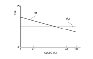
- FIG. 6A is a graph showing an example of the relationship between the first ratio R1 and the second ratio R2 and the index representing the operating state of the gas turbine 1.
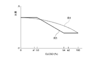
- FIG. 6B is a graph showing another example of the relationship between the first ratio R1 and the second ratio R2 and the index representing the operating state of the gas turbine 1.
- 6C and 6D are graphs showing other examples of the relationship between the first ratio R1 and the index representing the operating state of the gas turbine 1.
- FIG. 6E is a graph showing another example of the relationship between the second ratio R2 and the index representing the operating state of the gas turbine 1.
- a combustion load command value (a non-dimensional value obtained by making the gas turbine inlet combustion gas temperature T1T and the gas turbine inlet combustion gas temperature T1T non-dimensional) ( CLCSO)
- the load of the gas turbine 1 (generator output: gas turbine output) can be mentioned.
- the gas turbine inlet combustion gas temperature T1T is the temperature of the combustion gas at the inlet of the turbine 6.
- CLCSO will be described in detail later.
- the load of the gas turbine 1 may be a measured value of the generator output, or is a generator output command value sent from a central power supply center (not shown) that manages the generator outputs of a plurality of power generation facilities. May be good.
- the index may be the gas turbine inlet combustion gas temperature T1T.
- the gas turbine inlet combustion gas temperature T1T is an index that more accurately indicates the operating state of the gas turbine 1 as compared with, for example, the load of the gas turbine 1. If the index is the gas turbine inlet combustion gas temperature T1T, the relative ratio R can be more accurately reflected in the operating state of the gas turbine 1, so that the control accuracy of the relative ratio R can be improved. ..
- the indicator may be a dimensionless value (CLCSO) of the gas turbine inlet combustion gas temperature T1T.
- CLCSO dimensionless value
- the gas turbine inlet combustion gas temperature T1T is an index that more accurately indicates the operating state of the gas turbine 1 as compared with the load of the gas turbine 1, for example.
- the gas turbine inlet combustion gas temperature T1T has become high, and it is difficult to measure the gas turbine inlet combustion gas temperature T1T for a long time. If the index is CLCSO, it is not necessary to measure the gas turbine inlet combustion gas temperature T1T for a long time, and the control accuracy of the relative ratio R can be easily improved.
- the indicator may be the load of the gas turbine 1.
- the load of the gas turbine 1 is inferior in accuracy as an index indicating the operating state of the gas turbine 1 as compared with, for example, the gas turbine inlet combustion gas temperature T1T, it is easy to obtain a value. If the index is the load of the gas turbine 1, the configuration for controlling the relative ratio R can be simplified.
- the index representing the operating state of the gas turbine 1 is CLCSO
- the relationship between CLCSO and the first ratio R1 and the second ratio R2 described below will be described above other than CLCSO. It also applies to each index of.
- the lower limit of the first ratio R1 may be 0.
- the second fuel injector 42 is a combustor having a smaller risk of flashback than the first fuel injector 41. Therefore, as shown in FIGS. 6A and 6B, for example, the size of the CLC SO can be adjusted.
- the second ratio R2 may be a constant value. Note that, for example, as shown in FIG. 6E, the second ratio R2 may tend to decrease as the CLCSO increases.
- the absolute value of the rate of change of the second ratio R2 with respect to the change of CLCSO may be smaller than the absolute value of the rate of change of the first ratio R1 with respect to the change of CLCSO. That is, the rate of decrease in the second ratio R2 when CLCSO increases may be smaller than the rate of decrease in the first ratio R1 when CLCSO increases.
- the second fuel injector 42 is a combustor having a smaller risk of flashback than the first fuel injector 41, at least the CLCSO is relatively large, as shown in FIGS. 6A and 6B, for example.
- the second ratio R2 may be larger than the first ratio R1, and as shown in FIG. 6B, the second ratio R2 may be larger than the first ratio R1 regardless of the size of the CLCSO.
- the first ratio R1 may be a constant value regardless of the size of the CLCSO.
- the first ratio R1 is a constant value regardless of the size of CLCSO. May be.
- the first ratio R1 is a constant value regardless of the size of the CLCSO. May be.
- the first ratio R1 is constant regardless of the size of the CLCSO. It may be the value of.
- the first ratio R1 is a constant value regardless of the size of CLCSO. May be. In FIG. 6C, b1 ⁇ b2, and in FIG. 6D, b3 ⁇ b4.
- the first ratio R1 is constant regardless of the size of CLCSO in at least a part of the region where the size of CLCSO is b1% or more and b2% or less. It may be a value.
- the first ratio R1 in a part of the region where the size of CLCSO is b3% or more and b4% or less, the first ratio R1 may be a constant value regardless of the size of CLCSO.
- FIG. 6A or FIG. 6B there may be a portion of the graph line in which the first ratio R1 has a constant value regardless of the size of the CLC SO.
- the graph line of the first ratio R1 may be represented by a straight line like the graph line shown in FIGS. 6A to 6C and the graph line shown by the solid line in FIG. 6D.
- a straight line like the graph line shown in FIGS. 6A to 6C and the graph line shown by the solid line in FIG. 6D.
- the graph line shown by the broken line it may be represented by a curved line, or may be represented by, for example, a straight line and a curved line.
- the second ratio R2 is larger than the first ratio R1 at least in the region where the CLCSO is relatively large, the CLCSO has the same tendency as the above-mentioned change of the first ratio R1 with respect to the change of the CLCSO.
- the second ratio R2 may change with respect to the change.
- the first fuel injector 41 and the second fuel injector 42 have an index (for example, CLCSO) indicating an operating state as a first value a1 (see FIGS. 6A and 6B).
- the first ratio R1 is changed to the second ratio R2 than when the load of the gas turbine 1 becomes the second value a2 (see FIGS. 6A and 6B), which is higher than the case where the first value a1 is obtained.
- the first ratio R1 tends to decrease as the CLCSO increases, and as shown in FIGS. 6A and 6B, the second ratio regardless of the magnitude of the CLCSO.
- the value of R2 is constant, the value obtained by dividing the first ratio R1 by the second ratio R2 becomes larger when the CLCSO becomes the first value a1 than when the CLCSO becomes the second value a2.
- the second ratio R2 tends to decrease as the CLCSO increases, but when the CLCSO becomes the first value a1, the CLCSO becomes the second value. It is preferable that the value obtained by dividing the first ratio R1 by the second ratio R2 becomes larger than in the case of a2.
- the first fuel injector 41 is a combustor having a higher risk of flashback than the second fuel injector 42, the lower limit of the output in the turndown operation is reduced and the risk of flashback is reduced.
- the relative ratio R is desirable in order to achieve both.
- the controller that is, the combustion control device 140, has a first ratio R1 depending on whether the index (for example, CLCSO) is the first value a1 or the second value a2.
- the controller may be configured to control the low combustible fuel flow rate adjusting unit 240L and the high combustible fuel flow rate adjusting unit 240H so that at least one of the second ratio R2 is different. That is, the index becomes the first by making at least one of the first ratio R1 and the second ratio R2 different between the case where the index (for example, CLCSO) becomes the first value a1 and the case where the second value a2.
- the relative ratio R can be made different between the case where the first value is a1 and the case where the second value is a2.
- the controller that is, the combustion control device 140, has a first ratio when the index (for example, CLCSO) has a second value a2 than when the index (for example, CLCSO) has a first value a1.
- the low combustible fuel flow rate adjusting unit 240L and the high combustible fuel flow rate adjusting unit 240H may be controlled so that R1 becomes small. As a result, even if the load of the gas turbine 1 becomes relatively large, the risk of flashback in the first fuel injector 41, which has a higher risk of flashback than that of the second fuel injector 42, can be suppressed.
- the controller that is, the combustion control device 140, causes the second ratio R2 to be equal to or higher than the first ratio R1 when the index (for example, CLCSO) becomes the second value a2. It may be configured to control the low combustible fuel flow rate adjusting unit 240L and the high combustible fuel flow rate adjusting unit 240H. Therefore, since the first fuel injector 41 is a combustor having a higher risk of flashback than the second fuel injector 42, the reverse in the first fuel injector 41 when the load of the gas turbine 1 becomes relatively large.
- the second ratio R2 in the second fuel injector 42 can be relatively large while suppressing the risk of fire. For example, if the highly combustible fuel FH is a fuel having a relatively small environmental load such as hydrogen, the environmental load can be suppressed by relatively increasing the second ratio R2.
- the controller that is, the combustion control device 140, is low so that the second ratio R2 becomes 0.5 or more when the index (for example, CLCSO) becomes the second value a2. It may be configured to control the combustible fuel flow rate adjusting unit 240L and the highly combustible fuel flow rate adjusting unit 240H. As a result, when the load of the gas turbine 1 becomes relatively large, the second ratio R2 in the second fuel injector 42 can be made relatively large. For example, if the highly combustible fuel FH is a fuel having a relatively small environmental load such as hydrogen, the environmental load can be suppressed by relatively increasing the second ratio R2.
- FIG. 7 is an overall schematic view of the combustion control device 140 according to some embodiments.
- the combustion control device 140 according to some embodiments will be described with reference to FIG. 7.
- Each processing function of the combustion control device 140 is configured by software (computer program) and executed by a computer, but the present invention is not limited to this, and may be configured by hardware.
- the generator output command value is not limited to the case where it is sent from the central power supply center, and may be set by, for example, a generator output setter provided in a gas turbine power generation facility.
- the IGV opening command value is adopted here as the IGV opening used for calculating the CLC SO, it is not necessarily limited to this, and for example, when the IGV opening is measured, this measured value is used. You may use it.
- the generator output measured by the electric power meter PW, the intake air temperature measured by the intake air thermometer Ta, and the low combustible fuel gas are measured.
- Low combustible fuel temperature measured by thermometer Tfl, high combustible fuel temperature measured by high combustible fuel gas thermometer Tfh, exhaust gas temperature measured by exhaust gas thermometer Th, and intake flow meter FX1 The measured intake air flow rate, the turbine bypass flow rate measured by the turbine bypass flow meter FX2, the intake air pressure measured by the intake air pressure gauge PX4, and the vehicle interior pressure measured by the vehicle interior pressure gauge PX5 are input.
- the turbine bypass flow rate is the flow rate of compressed air that flows through a turbine bypass line (not shown) without passing through the combustor 4 and the turbine 6.
- a turbine bypass line (not shown) is provided with a turbine bypass valve (not shown) for adjusting the turbine bypass flow rate of compressed air. This is provided for adjusting the outlet pressure (cabin pressure) of the compressor 2.
- the L1 valve opening command value for adjusting the supply amount of the low combustible fuel FL to the first fuel injector 41 based on these input signals and the like.
- the H1 valve opening command value and the H2 valve opening command value for adjusting the supply amount of the highly combustible fuel FH to the second fuel injector 42 are obtained.
- the L1 valve opening command value is a command value of the valve opening degree in the L1 flow rate adjusting unit 241
- the L2 valve opening command value is a command value of the valve opening degree in the L2 flow rate adjusting unit 242.
- the H1 valve opening command value is a command value of the valve opening degree in the H1 flow rate adjusting unit 243
- the H2 valve opening command value is a command value of the valve opening degree in the H2 flow rate adjusting unit 244.
- the L1 valve opening command value, the L2 valve opening command value, the H1 valve opening command value, and the H2 valve opening command value have the same relationship as described above between CLCSO and the first ratio R1 and the second ratio R2. Is calculated as follows.
- the valve opening in the L1 flow rate adjusting unit 241 is set to the valve opening corresponding to the L1 valve opening command value, so that low combustion with respect to the first fuel injector 41 is performed.
- the supply amount of the sex fuel FL is adjusted.
- the valve opening degree in the H1 flow rate adjusting unit 243 is set to the valve opening degree corresponding to the H1 valve opening degree command value, so that the valve opening degree is set with respect to the first fuel injector 41.
- the supply of highly combustible fuel FH is adjusted. As a result, the low combustible fuel FL and the high combustible fuel FH are supplied to the first fuel injector 41 at the first ratio R1 calculated and set by the combustion control device 140.
- the valve opening in the L2 flow rate adjusting unit 242 is set to the valve opening corresponding to the L2 valve opening command value, so that low combustion with respect to the second fuel injector 42 is performed.
- the supply amount of the sex fuel FL is adjusted.
- the valve opening degree in the H2 flow rate adjusting unit 244 is set to the valve opening degree corresponding to the H2 valve opening degree command value, so that the second fuel injector 42 is provided.
- the supply of highly combustible fuel FH is adjusted.
- the low combustible fuel FL and the high combustible fuel FH are supplied to the second fuel injector 42 at the second ratio R2 calculated and set by the combustion control device 140.
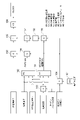
- FIG. 8 is a block diagram showing a configuration of CLCSO calculation logic in the combustion control device 140 according to some embodiments.
- the combustion load command value (CLCSO) is a parameter that makes the gas turbine inlet combustion gas temperature T1T dimensionless, and has a positive correlation with this gas turbine inlet combustion gas temperature T1T (proportional to the gas turbine inlet combustion gas temperature T1T). ) It is a parameter.
- This CLCSO is set to be 0% when the gas turbine inlet combustion gas temperature T1T is the lower limit value and 100% when the gas turbine inlet combustion gas temperature T1T is the upper limit value. For example, when the lower limit of the gas turbine inlet combustion gas temperature T1T is 700 ° C. and the upper limit of the gas turbine inlet combustion gas temperature T1T is 1500 ° C., CLCSO is expressed by the following equation (1).
- CLCSO (%) ⁇ (actual output-700 ° C MW) / (1500 ° C MW) -700 ° C MW) ⁇ x 100 ...
- the actual output is the measured gas turbine output (generator output).
- 700 ° C. MW is the output (generator output) of the gas turbine 1 when the gas turbine inlet combustion gas temperature T1T is 700 ° C., which is the lower limit value, in the environment where the gas turbine 1 is currently placed.
- 1500 ° C. MW is the output (generator output) of the gas turbine 1 when the gas turbine inlet combustion gas temperature T1T is 1500 ° C., which is the upper limit value, under the current environment of the gas turbine 1.
- the intake air temperature of the measured value, the IGV opening command value, and the intake flow rate of the measured value in the divider 153 (total compressed air).
- the value of 1500 ° C. MW (temperature control MW) is calculated based on the turbine bypass ratio (turbine bypass flow rate / intake flow rate) obtained by dividing the measured value of the turbine bypass flow rate (corresponding to the amount). That is, the value of 1500 ° C. MW in consideration of the IGV opening degree, the intake air temperature and the turbine bypass ratio is obtained.
- the function generator 152 calculates the value of 700 ° C. MW based on the intake air temperature, the IGV opening command value, and the turbine bypass ratio. That is, the value of 700 ° C. MW in consideration of the IGV opening degree, the intake air temperature and the turbine bypass ratio is obtained.
- the divider 154 divides the measured intake pressure (atmospheric pressure) and the standard atmospheric pressure set by the signal generator 161 to obtain the atmospheric pressure ratio (intake pressure / standard atmospheric pressure).
- the value of 1500 ° C. MW obtained by the function generator 151 is multiplied by the atmospheric pressure ratio obtained by the divider 154 to obtain the value of 1500 ° C. MW in consideration of the atmospheric pressure ratio.
- the value of 1500 ° C. MW obtained by the multiplier 155 may be output to the subtractor 157 via the learning circuit 162, or may be directly output to the subtractor 157.
- the learning circuit 162 is for correcting the deviation of the value of 1500 ° C. MW due to the deterioration of the characteristics of the gas turbine 1.
- the value of 700 ° C. MW obtained by the function generator 152 is multiplied by the atmospheric pressure ratio obtained by the divider 154 to obtain the value of 700 ° C. MW in consideration of the atmospheric pressure ratio.
- the value of 700 ° C. MW obtained by the multiplier 156 is subtracted from the value of 1500 ° C. MW obtained by the multiplier 155 (or corrected by the learning circuit 162) (1500 ° C. MW-700 ° C. MW: See equation (1) above).
- the value of 700 ° C. MW obtained by the multiplier 156 is subtracted from the actual output, that is, the generator output (gas turbine output) of the actually measured value (actual output-700 ° C. MW: see the above equation (1)). ..
- the CLCSO can be calculated.
- the output value of the divider 159 may be multiplied by 100.
- the CLC SO does not frequently repeat the opening / closing operation due to the minute fluctuation of the CLC SO due to the minute fluctuation of the gas turbine output (generator output). Therefore, the input value from the divider 159 is not immediately output as CLCSO, but is limited to a predetermined increase / decrease rate and output.
- the present disclosure is not limited to the above-mentioned embodiment, and includes a form in which the above-mentioned embodiment is modified and a form in which these forms are appropriately combined.
- the contents described in each of the above embodiments are grasped as follows, for example.
- the gas turbine combustor 4 according to at least one embodiment of the present disclosure is injected from a first fuel injector 41, a second fuel injector 42, a first fuel injector 41, and a second fuel injector 42.
- Low combustion for independently adjusting the supply amount of the low combustible fuel FL to the combustor liner 46 as a combustion part where the fuel F is burned and the first fuel injector 41 and the second fuel injector 42.
- the highly combustible fuel flow rate adjusting unit 240H and the combustion control device 140 as a controller are provided.
- the controller has a first ratio R1 of the highly combustible fuel FH to the entire first fuel F1 injected by the first fuel injector 41 and a second, depending on the operating state of the gas turbine 1.
- the first fuel injector 41 and the second fuel injector 42 have the first value a1 when the index indicating the operating state is the first value a1.
- the relative ratio R is set as described above, if the first fuel injector 41 is a combustor having a higher risk of flashback than the second fuel injector 42, the lower limit of output in the turndown operation should be reduced.
- the relative ratio R is desirable in order to achieve both the above and the reduction of the risk of flashback.
- the controller (combustion control device 140) has a first value depending on whether the index has the first value a1 or the second value a2.
- the low combustible fuel flow rate adjusting unit 240L and the high combustible fuel flow rate adjusting unit 240H may be controlled so that at least one of the ratio R1 and the second ratio R2 is different.
- the relative ratio R can be different depending on whether the index has the first value a1 or the second value a2.
- the controller (combustion control device 140) has a second value a2 rather than a first value a1. May be configured to control the low combustible fuel flow rate adjusting unit 240L and the high combustible fuel flow rate adjusting unit 240H so that the first ratio R1 becomes smaller.
- the risk of flashback in the first fuel injector 41 can be suppressed even if the load of the gas turbine 1 becomes relatively large.
- the controller (combustion control device 140) has a second ratio R2 when the index is the second value a2. It may be configured to control the low combustible fuel flow rate adjusting unit 240L and the high combustible fuel flow rate adjusting unit 240H so as to have the first ratio R1 or more.
- the load of the gas turbine 1 becomes relatively large.
- the second ratio R2 in the second fuel injector 42 can be made relatively large while suppressing the risk of flashback in the first fuel injector 41.
- the highly combustible fuel FH is a fuel having a relatively small environmental load such as hydrogen, the environmental load can be suppressed by relatively increasing the second ratio R2.
- the controller (combustion control device 140) has a second ratio R2 when the index is the second value a2. It may be configured to control the low combustible fuel flow rate adjusting unit 240L and the high combustible fuel flow rate adjusting unit 240H so as to be 0.5 or more.
- the second ratio R2 in the second fuel injector 42 can be made relatively large.
- the highly combustible fuel FH is a fuel having a relatively small environmental load such as hydrogen
- the environmental load can be suppressed by relatively increasing the second ratio R2.
- the first fuel injector 41 may be a premixed combustion type fuel injector, and the second fuel.
- the injector 42 may be a diffusion combustion type fuel injector.
- a diffusion combustion type fuel injector is a combustor having a lower risk of flashback than a premixed combustion type fuel injector.
- the second fuel injector 42 is a combustor having a smaller risk of flashback than the first fuel injector 41.
- a plurality of first fuel injectors 41 may be arranged around the second fuel injector 42.
- the enclosed fuel injector is at greater risk of flashback than the surrounding fuel injector. It gets smaller.
- the second fuel injector 42 is a combustor having a smaller risk of flashback than the first fuel injector 41.
- the first fuel injector 41 is arranged coaxially with the second fuel injector 42 and is a second fuel injector. It may be configured to inject the first fuel F1 from around 42.
- one fuel injector is placed coaxially with the other fuel injector, and each fuel injector is configured such that one fuel injector injects fuel from around the other fuel injector. If so, the other fuel injector has a lower risk of flashback than the one fuel injector.
- the second fuel injector 42 is a combustor having a smaller risk of flashback than the first fuel injector 41.
- the index representing the operating state may be the gas turbine inlet combustion gas temperature T1T.
- the gas turbine inlet combustion gas temperature T1T is an index that more accurately indicates the operating state of the gas turbine 1 as compared with, for example, the load (gas turbine output) of the gas turbine 1. According to the configuration of the above (10), since the relative ratio R can more accurately reflect the operating state of the gas turbine 1, the control accuracy of the relative ratio R can be improved.
- the index representing the operating state is a dimensionless value (CLCSO) of the gas turbine inlet combustion gas temperature T1T. It is good.
- the gas turbine inlet combustion gas temperature T1T is an index that more accurately indicates the operating state of the gas turbine 1 as compared with, for example, the load (gas turbine output) of the gas turbine 1.
- the gas turbine inlet combustion gas temperature T1T has become high, and it is difficult to measure the gas turbine inlet combustion gas temperature T1T for a long time.
- the configuration of (11) above by using the nondimensionalized value (CLCSO) of the gas turbine inlet combustion gas temperature T1T as the above index, it is not necessary to measure the gas turbine inlet combustion gas temperature T1T for a long time.
- the control accuracy of the relative ratio R can be easily improved.
- the index representing the operating state may be the load of the gas turbine 1.
- the load of the gas turbine 1 is inferior in accuracy as an index indicating the operating state of the gas turbine 1 as compared with, for example, the gas turbine inlet combustion gas temperature T1T, it is easy to obtain a value.
- the configuration for controlling the relative ratio R can be simplified.
- the low combustible fuel FL may be natural gas
- the high combustible fuel FH may be hydrogen or propane. , Or a mixture of hydrogen and propane.
- the low combustible fuel FL may be natural gas, which is a general fuel for the gas turbine 1.
- the highly combustible fuel FH may be any of hydrogen, propane, or a mixture of hydrogen and propane, which is a fuel having a higher combustion rate than natural gas. Thereby, the increase in the cost of the fuel F can be suppressed.
- the gas turbine 1 according to at least one embodiment of the present disclosure includes a gas turbine combustor 4 having any of the above configurations (1) to (13).
Landscapes
- Engineering & Computer Science (AREA)
- Chemical & Material Sciences (AREA)
- Combustion & Propulsion (AREA)
- Mechanical Engineering (AREA)
- General Engineering & Computer Science (AREA)
Priority Applications (5)
| Application Number | Priority Date | Filing Date | Title |
|---|---|---|---|
| US18/269,115 US12435878B2 (en) | 2021-01-08 | 2021-12-28 | Gas turbine combustor with less combustable fuel and highly combustible fuel ratio control |
| DE112021005603.4T DE112021005603T5 (de) | 2021-01-08 | 2021-12-28 | Gasturbinenbrennkammer und gasturbine |
| KR1020237021005A KR102789952B1 (ko) | 2021-01-08 | 2021-12-28 | 가스 터빈 연소기 및 가스 터빈 |
| JP2022574034A JP7456012B2 (ja) | 2021-01-08 | 2021-12-28 | ガスタービン燃焼器及びガスタービン |
| CN202180089044.4A CN116710643A (zh) | 2021-01-08 | 2021-12-28 | 燃气轮机燃烧器及燃气轮机 |
Applications Claiming Priority (2)
| Application Number | Priority Date | Filing Date | Title |
|---|---|---|---|
| JP2021002117 | 2021-01-08 | ||
| JP2021-002117 | 2021-01-08 |
Publications (1)
| Publication Number | Publication Date |
|---|---|
| WO2022149540A1 true WO2022149540A1 (ja) | 2022-07-14 |
Family
ID=82357752
Family Applications (1)
| Application Number | Title | Priority Date | Filing Date |
|---|---|---|---|
| PCT/JP2021/048742 Ceased WO2022149540A1 (ja) | 2021-01-08 | 2021-12-28 | ガスタービン燃焼器及びガスタービン |
Country Status (6)
| Country | Link |
|---|---|
| US (1) | US12435878B2 (https=) |
| JP (1) | JP7456012B2 (https=) |
| KR (1) | KR102789952B1 (https=) |
| CN (1) | CN116710643A (https=) |
| DE (1) | DE112021005603T5 (https=) |
| WO (1) | WO2022149540A1 (https=) |
Cited By (5)
| Publication number | Priority date | Publication date | Assignee | Title |
|---|---|---|---|---|
| JPWO2024116963A1 (https=) * | 2022-12-01 | 2024-06-06 | ||
| WO2025033089A1 (ja) * | 2023-08-04 | 2025-02-13 | 三菱重工業株式会社 | ガスタービン制御装置、ガスタービン制御方法、及び、ガスタービン改造方法 |
| WO2025094681A1 (ja) * | 2023-10-30 | 2025-05-08 | 三菱重工業株式会社 | 燃料ガス加熱装置、及び、コンバインドサイクルプラント |
| US12473861B2 (en) | 2023-06-07 | 2025-11-18 | Mitsubishi Heavy Industries, Ltd. | Fuel supply device for gas turbine and method for controlling fuel supply device for gas turbine |
| US12486806B2 (en) | 2024-02-15 | 2025-12-02 | Mitsubishi Heavy Industries, Ltd. | Operation method for gas turbine and control device for gas turbine |
Citations (3)
| Publication number | Priority date | Publication date | Assignee | Title |
|---|---|---|---|---|
| JP5873239B2 (ja) * | 2009-10-23 | 2016-03-01 | ゼネラル・エレクトリック・カンパニイ | 燃料フレキシブル燃焼器システム及び方法 |
| JP6431893B2 (ja) * | 2013-03-15 | 2018-11-28 | ゼネラル・エレクトリック・カンパニイ | ガスタービンの燃料混合および制御のためのシステムおよび方法 |
| WO2019048387A1 (en) * | 2017-09-05 | 2019-03-14 | Siemens Aktiengesellschaft | GAS TURBINE COMBUSTION CHAMBER ASSEMBLY WITH TRAPPED TOURBILLON ELEMENT |
Family Cites Families (30)
| Publication number | Priority date | Publication date | Assignee | Title |
|---|---|---|---|---|
| US4949538A (en) * | 1988-11-28 | 1990-08-21 | General Electric Company | Combustor gas feed with coordinated proportioning |
| AU1748192A (en) * | 1991-12-26 | 1993-07-28 | Solar Turbines Incorporated | Low emission combustion system for a gas turbine engine |
| EP0915406B1 (de) * | 1997-11-10 | 2003-05-07 | ALSTOM (Switzerland) Ltd | Verfahren zur Überwachung des Versorgungssystems einer Gasturbine mit Mehrbrennersystem sowie Vorrichtung zur Durchführung des Verfahrens |
| EP0952317A3 (en) * | 1998-04-21 | 2002-04-17 | Mitsubishi Heavy Industries, Ltd. | Purging system for a gas turbine fuel supply |
| JP2002195565A (ja) * | 2000-12-26 | 2002-07-10 | Mitsubishi Heavy Ind Ltd | ガスタービン燃焼器 |
| US6640548B2 (en) * | 2001-09-26 | 2003-11-04 | Siemens Westinghouse Power Corporation | Apparatus and method for combusting low quality fuel |
| US7162864B1 (en) * | 2003-11-04 | 2007-01-16 | Sandia National Laboratories | Method for control of NOx emission from combustors using fuel dilution |
| JP4119909B2 (ja) | 2005-09-14 | 2008-07-16 | 三菱重工業株式会社 | ガスタービンの燃焼制御装置 |
| JP4979615B2 (ja) * | 2008-03-05 | 2012-07-18 | 株式会社日立製作所 | 燃焼器及び燃焼器の燃料供給方法 |
| US7921651B2 (en) * | 2008-05-05 | 2011-04-12 | General Electric Company | Operation of dual gas turbine fuel system |
| US20100095649A1 (en) | 2008-10-20 | 2010-04-22 | General Electric Company | Staged combustion systems and methods |
| US20100170253A1 (en) * | 2009-01-07 | 2010-07-08 | General Electric Company | Method and apparatus for fuel injection in a turbine engine |
| US8833052B2 (en) * | 2009-11-30 | 2014-09-16 | General Electric Company | Systems and methods for controlling fuel mixing |
| JP5566683B2 (ja) | 2009-12-25 | 2014-08-06 | 三菱重工業株式会社 | ガスタービン |
| US8627668B2 (en) * | 2010-05-25 | 2014-01-14 | General Electric Company | System for fuel and diluent control |
| US20110296844A1 (en) | 2010-06-02 | 2011-12-08 | General Electric Company | Gas turbine combustion system with rich premixed fuel reforming and methods of use thereof |
| EP2458181A1 (de) | 2010-11-30 | 2012-05-30 | Siemens Aktiengesellschaft | Verfahren zum Betreiben einer Gasturbine, Vorrichtung zum Regeln des Betriebs einer Gasturbine und Kraftwerk |
| US9243804B2 (en) * | 2011-10-24 | 2016-01-26 | General Electric Company | System for turbine combustor fuel mixing |
| US8973366B2 (en) * | 2011-10-24 | 2015-03-10 | General Electric Company | Integrated fuel and water mixing assembly for use in conjunction with a combustor |
| US20140000274A1 (en) * | 2012-06-29 | 2014-01-02 | Ram Srinivasan | Methods and apparatus for co-firing fuel |
| US20140157788A1 (en) * | 2012-12-06 | 2014-06-12 | General Electric Company | Fuel nozzle for gas turbine |
| JP6463947B2 (ja) * | 2014-11-05 | 2019-02-06 | 川崎重工業株式会社 | バーナ、燃焼器、及びガスタービン |
| US10012387B2 (en) * | 2014-12-05 | 2018-07-03 | General Electric Company | Fuel supply system for a gas turbine engine |
| US10234142B2 (en) * | 2016-04-15 | 2019-03-19 | Solar Turbines Incorporated | Fuel delivery methods in combustion engine using wide range of gaseous fuels |
| US10247155B2 (en) * | 2016-04-15 | 2019-04-02 | Solar Turbines Incorporated | Fuel injector and fuel system for combustion engine |
| JP6978855B2 (ja) * | 2017-05-16 | 2021-12-08 | 川崎重工業株式会社 | ガスタービン燃焼器およびその運転方法 |
| JP7348591B2 (ja) | 2019-06-20 | 2023-09-21 | マツダ株式会社 | 見守り支援方法、見守り管理装置 |
| US12163665B2 (en) * | 2019-07-08 | 2024-12-10 | Opra Technologies Bv | Nozzle and fuel system for operation on gas with varying heating value |
| JP7200077B2 (ja) * | 2019-10-01 | 2023-01-06 | 三菱重工業株式会社 | ガスタービン燃焼器及びその運転方法 |
| US11261803B2 (en) * | 2020-03-05 | 2022-03-01 | General Electric Company | Method and system for fuel nozzle cleaning during engine operation |
-
2021
- 2021-12-28 WO PCT/JP2021/048742 patent/WO2022149540A1/ja not_active Ceased
- 2021-12-28 KR KR1020237021005A patent/KR102789952B1/ko active Active
- 2021-12-28 JP JP2022574034A patent/JP7456012B2/ja active Active
- 2021-12-28 CN CN202180089044.4A patent/CN116710643A/zh active Pending
- 2021-12-28 DE DE112021005603.4T patent/DE112021005603T5/de active Pending
- 2021-12-28 US US18/269,115 patent/US12435878B2/en active Active
Patent Citations (3)
| Publication number | Priority date | Publication date | Assignee | Title |
|---|---|---|---|---|
| JP5873239B2 (ja) * | 2009-10-23 | 2016-03-01 | ゼネラル・エレクトリック・カンパニイ | 燃料フレキシブル燃焼器システム及び方法 |
| JP6431893B2 (ja) * | 2013-03-15 | 2018-11-28 | ゼネラル・エレクトリック・カンパニイ | ガスタービンの燃料混合および制御のためのシステムおよび方法 |
| WO2019048387A1 (en) * | 2017-09-05 | 2019-03-14 | Siemens Aktiengesellschaft | GAS TURBINE COMBUSTION CHAMBER ASSEMBLY WITH TRAPPED TOURBILLON ELEMENT |
Cited By (7)
| Publication number | Priority date | Publication date | Assignee | Title |
|---|---|---|---|---|
| JPWO2024116963A1 (https=) * | 2022-12-01 | 2024-06-06 | ||
| WO2024116963A1 (ja) * | 2022-12-01 | 2024-06-06 | 三菱重工業株式会社 | ガスタービンの運転方法 |
| JP7780037B2 (ja) | 2022-12-01 | 2025-12-03 | 三菱重工業株式会社 | ガスタービンの運転方法 |
| US12473861B2 (en) | 2023-06-07 | 2025-11-18 | Mitsubishi Heavy Industries, Ltd. | Fuel supply device for gas turbine and method for controlling fuel supply device for gas turbine |
| WO2025033089A1 (ja) * | 2023-08-04 | 2025-02-13 | 三菱重工業株式会社 | ガスタービン制御装置、ガスタービン制御方法、及び、ガスタービン改造方法 |
| WO2025094681A1 (ja) * | 2023-10-30 | 2025-05-08 | 三菱重工業株式会社 | 燃料ガス加熱装置、及び、コンバインドサイクルプラント |
| US12486806B2 (en) | 2024-02-15 | 2025-12-02 | Mitsubishi Heavy Industries, Ltd. | Operation method for gas turbine and control device for gas turbine |
Also Published As
| Publication number | Publication date |
|---|---|
| US20240125476A1 (en) | 2024-04-18 |
| CN116710643A (zh) | 2023-09-05 |
| KR102789952B1 (ko) | 2025-04-01 |
| KR20230112676A (ko) | 2023-07-27 |
| DE112021005603T5 (de) | 2023-08-03 |
| JPWO2022149540A1 (https=) | 2022-07-14 |
| JP7456012B2 (ja) | 2024-03-26 |
| US12435878B2 (en) | 2025-10-07 |
Similar Documents
| Publication | Publication Date | Title |
|---|---|---|
| WO2022149540A1 (ja) | ガスタービン燃焼器及びガスタービン | |
| US10865989B2 (en) | Combustor arrangement having arranged in an upstream to downstream flow sequence a radial swirler, pre-chamber with a convergent portion and a combustion chamber | |
| US20200025385A1 (en) | Centerbody Injector Mini Mixer Fuel Nozzle Assembly | |
| EP1087178B1 (en) | Pre-mixing chamber for gas turbines | |
| JP2019090405A (ja) | 主燃料回路およびパイロット燃料回路を有する燃焼システムを動作させる方法 | |
| JP6626743B2 (ja) | 燃焼装置及びガスタービン | |
| CN106762158B (zh) | 用于操作燃气涡轮的同时维持排放标准的系统和方法 | |
| CN109072782B (zh) | 燃烧器及燃气轮机 | |
| JP2013140003A5 (https=) | ||
| CN102809176A (zh) | 气动力燃料喷嘴 | |
| US12404813B2 (en) | Control method for gas turbine combustor and control device for gas turbine combustor | |
| JP2014102066A (ja) | ガスタービンの燃焼セクションに燃料を供給するための燃料供給システム | |
| US12486982B2 (en) | Combustor having a main chamber and one or more trapped vortex cavities | |
| RU2657075C2 (ru) | Жидкостная пусковая трубка с кожухом | |
| US20240263783A1 (en) | Hydrogen-driven gas turbine engine with injector ring | |
| CN116761957A (zh) | 操作用于燃气涡轮机的燃烧器的方法 | |
| US20140157788A1 (en) | Fuel nozzle for gas turbine | |
| JP4409566B2 (ja) | 希薄予混合型燃焼装置とその制御方法 | |
| JP4995657B2 (ja) | ガスタービンエンジン燃焼器のミキサ組立体への燃料流量を能動的に制御するための装置 | |
| JP6193131B2 (ja) | 燃焼器およびガスタービン | |
| JP7780037B2 (ja) | ガスタービンの運転方法 | |
| WO2013151162A1 (ja) | ガスタービン燃焼器 | |
| US11280496B2 (en) | Gas turbine engine and methods of controlling emissions therefrom | |
| JP7847232B2 (ja) | ガスタービンの運転方法 | |
| EP4477950A1 (en) | Combustion system |
Legal Events
| Date | Code | Title | Description |
|---|---|---|---|
| 121 | Ep: the epo has been informed by wipo that ep was designated in this application |
Ref document number: 21917760 Country of ref document: EP Kind code of ref document: A1 |
|
| ENP | Entry into the national phase |
Ref document number: 2022574034 Country of ref document: JP Kind code of ref document: A |
|
| ENP | Entry into the national phase |
Ref document number: 20237021005 Country of ref document: KR Kind code of ref document: A |
|
| WWE | Wipo information: entry into national phase |
Ref document number: 18269115 Country of ref document: US |
|
| WWE | Wipo information: entry into national phase |
Ref document number: 202180089044.4 Country of ref document: CN |
|
| 122 | Ep: pct application non-entry in european phase |
Ref document number: 21917760 Country of ref document: EP Kind code of ref document: A1 |
|
| WWG | Wipo information: grant in national office |
Ref document number: 1020237021005 Country of ref document: KR |
|
| WWG | Wipo information: grant in national office |
Ref document number: 18269115 Country of ref document: US |