WO2022149247A1 - 希少手順生成装置、希少手順生成方法及びプログラム - Google Patents
希少手順生成装置、希少手順生成方法及びプログラム Download PDFInfo
- Publication number
- WO2022149247A1 WO2022149247A1 PCT/JP2021/000394 JP2021000394W WO2022149247A1 WO 2022149247 A1 WO2022149247 A1 WO 2022149247A1 JP 2021000394 W JP2021000394 W JP 2021000394W WO 2022149247 A1 WO2022149247 A1 WO 2022149247A1
- Authority
- WO
- WIPO (PCT)
- Prior art keywords
- function
- data
- prediction
- log
- functions
- Prior art date
- Legal status (The legal status is an assumption and is not a legal conclusion. Google has not performed a legal analysis and makes no representation as to the accuracy of the status listed.)
- Ceased
Links
Images






Classifications
-
- G—PHYSICS
- G06—COMPUTING OR CALCULATING; COUNTING
- G06F—ELECTRIC DIGITAL DATA PROCESSING
- G06F11/00—Error detection; Error correction; Monitoring
- G06F11/36—Prevention of errors by analysis, debugging or testing of software
-
- G—PHYSICS
- G06—COMPUTING OR CALCULATING; COUNTING
- G06N—COMPUTING ARRANGEMENTS BASED ON SPECIFIC COMPUTATIONAL MODELS
- G06N5/00—Computing arrangements using knowledge-based models
- G06N5/04—Inference or reasoning models
Definitions
- the embodiment relates to a rare procedure generator, a rare procedure generation method, and a program for verification that can be used in system development, for example.
- the verification may be carried out focusing on the semi-normal operation and the rare operation.
- the target of rare movements is all patterns except normal movements and procedures. In other words, even if it is a rare operation, the target is wide-ranging, so it is generally difficult to select the target to be verified.
- verification items are manually formulated, so there is room for consideration not only inefficiency but also in terms of quality. When the number of verification items can be enormous, attempts are being made to generate verification items using the log, which is the usage history of the system.
- the embodiment is intended to provide a technique capable of extracting a rare procedure for verification from a commercial log.
- the rare procedure generation device includes a prediction unit, a filtering processing unit, and an extraction processing unit.
- the prediction unit uses a learning model that learns the order of use of functions based on the first data for learning, which is a log in which the order of use of functions in a system having multiple functions is recorded. From the second data for prediction, which is a log in which some of the functions in the order are missing, the missing functions are predicted together with the prediction probability.
- the filtering processing unit determines whether or not the prediction probability is greater than zero and equal to or less than the threshold value.
- the extraction processing unit extracts the second data according to the determination result of the filtering processing unit.
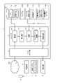
- FIG. 1 is a diagram showing an example of a system including a rare procedure generator according to the first embodiment.
- FIG. 2A is a diagram showing an example of log data stored in a log database.
- FIG. 2B is a diagram showing an example of log data stored in a log database.
- FIG. 3A is a diagram showing an example of target function data.
- FIG. 3B is a diagram showing an example of probability threshold data.
- FIG. 4 is a diagram showing an example of preprocessed learning log data.
- FIG. 5 is an example of a decision tree used in the prediction unit.
- FIG. 6A is a diagram showing an example of prediction result data.
- FIG. 6B is a diagram showing an example of a true utilization function table.
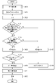
- FIG. 7 is a flowchart showing the operation of the rare procedure generator according to the first embodiment.
- FIG. 8 is a diagram showing an example of a system including a rare procedure generator according to a second embodiment.
- FIG. 9A is a diagram showing an example of a functional transition rule table.
- FIG. 9B is a diagram showing an example of a function table used immediately before the prediction target.
- FIG. 10 is a diagram showing an example of prediction result data.
- FIG. 11 is a flowchart showing the operation of the rare procedure generator according to the second embodiment.
- the verification items for the rare procedure which is a rare procedure
- the rare procedure is a procedure in which the functions transition in the rare order among the usage order of the plurality of functions implemented in the business system.
- a function to be verified is set in advance, and a rare procedure in a series of usage procedures including the function is extracted using a log.
- the log can also be understood as a usage history of a function implemented in a business system. Therefore, for example, each of the procedures for using a plurality of functions can be defined as a log.
- the same function may be used repeatedly.
- a learning model that predicts the usage procedure of a plurality of functions is formed by learning the logs accumulated in the past.
- a log with a defect is prepared in a part of the procedure separately from the log used in the learning, and the log is applied to the trained learning model, so that the function of the position of the defect is predicted. To. Those with a low prediction probability of this predicted function correspond to the rare procedure.
- the last-use function which is the function used at the end of the procedure, is the missing part.
- the generation of a rare procedure is described using the log data for which the final utilization function of the procedure is known.
- the generation of a rare procedure is described using log data for which the final utilization function of the procedure is unknown.
- the situation assumed in the first embodiment is a situation in which a part of the log is used as it is for verification.
- the situation assumed in the second embodiment is a situation in which the verification item is designed under a complex condition such that the target function that the system user wants to verify is executed after a specific procedure.
- FIG. 1 is a diagram showing an example of a system including a rare procedure generator according to the first embodiment.
- the rare procedure generation device 1 generates a verification item for verifying an application 5 implemented in, for example, a business system 4.
- the functions provided in the business system 4 are mainly provided by the application 5. As the development of the application 5 continues, new functions may be implemented in the business system 4.
- verification work can be performed before the system goes into operation, including bug fixes.
- the verification items related to the rare procedure can be generated.
- the rare procedure generator 1 includes a processor 11, a storage 12, an interface unit 13, and a memory 14.
- the rare procedure generator 1 is a computer, and is realized as, for example, a personal computer, a server computer, or the like.
- the interface unit 13 is connected to the network 100, and can exchange various data with and from the business system 4 via the management terminal 2 similarly connected to the network 100.
- the storage 12 is a non-volatile storage medium (block device) such as an HDD (Hard Disk Drive) and an SSD (Solid State Drive).
- the storage 12 stores a log database 12a in addition to a basic program such as an OS (Operating System) and a device driver, a program for realizing the function of the rare procedure generation device 1, and the like. Further, the storage 12 stores the learning model 12b.
- FIGS. 2A and 2B are diagrams showing an example of log data stored in the log database 12a.
- the log data stored in the log database 12a includes learning log data and prediction log data.
- FIG. 2A is a diagram showing an example of data of a log for learning
- FIG. 2B is a diagram showing an example of data of a log for prediction.
- the learning log data is the data of the table that stores the function ID and the time series information in association with each other.
- the function ID is data of a function identifier uniquely assigned to each function of the business system 4.
- the time-series information is data on the date and time when the function of the corresponding function ID was actually used.
- the function IDs from the function ID of the function first used for the specific operation of the business system 4 to the last use function which is the last used function are recorded in chronological order together with the date and time of use.
- the data D11 indicates that seven functions are used for a certain operation of the business system 4, the first function used is the function of the function ID F001, and the last used function is the function of the function ID F004. ing.
- the number of function IDs that is, the number of functions, which is an item in the procedure, may be any number. Further, the number of functions used for one operation is not limited to seven.
- the data of the log for prediction is the data of the log for learning in which the function ID of the function of some procedures is missing.
- the data D21 is data in which the function ID of the last-use function is missing.
- the missing function ID can be the function ID to be predicted.
- the data of such a log for prediction may be generated by deleting a part of the data of the log for learning.
- the function ID in the data of the log for prediction is common to the function ID in the data of the log for learning.
- the time-series information in the data of the log for prediction is the date and time when the specific operation of the business system 4 is scheduled to be used.
- the position where the function ID is missing in the data of the log for prediction may be arbitrarily determined by the system user of the rare procedure generator 1.
- the learning log data and the prediction log data may include data other than the function ID and time series information.
- a unique data ID is associated with each learning log data and each prediction log data.
- the log data for learning is continuously collected by, for example, the log collection function of the application 5 or the management terminal 2 connected to the business system 4.
- the collected log may be stored in the log database 12a as described above, or may be recorded in, for example, a storage medium 6 after removing privacy information.
- the logs may be stored in, for example, a key-value type, SQL type, or NoSQL type database and provided via the cloud.
- the log may be any log as long as it can be accessed from the rare procedure generator 1.
- the memory 14 includes, for example, a RAM (RandomAccessMemory).
- the memory 14 stores the target function data 14b and the probability threshold data 14c in addition to the program 14a loaded from the storage 12.
- FIG. 3A is a diagram showing an example of target function data 14b.
- the target function data 14b is data including the function ID of the target function that the system user wants to verify.
- the function ID F002 is the target function of this time.
- the function ID as the target function data 14b can be arbitrarily set by, for example, a system user.
- FIG. 3B is a diagram showing an example of probability threshold data 14c.
- the probability threshold data 14c is the data of the threshold value of the prediction probability of the function for determining the rarity of the occurrence of the function.
- the probability threshold data 14c is represented by, for example, a percentage. In the prediction described later, it is determined that the procedure including the function whose prediction probability of the predicted function is greater than zero and equal to or less than the threshold value is a rare procedure.
- the threshold value as the probability threshold data 14c can be arbitrarily set by, for example, a system user.
- the processor 11 is, for example, an arithmetic unit such as a Central Processing Unit (CPU) or a MicroProcessingUnit (MPU), and performs various processes according to a program loaded in the memory 14.
- the processor 11 may be composed of a single CPU or the like, or may be composed of a plurality of CPUs or the like.
- the processor 11 can operate as an acquisition unit 111, a preprocessing unit 112, a prediction unit 113, a filtering processing unit 114, and an extraction processing unit 115 by executing an instruction included in the program 14a.
- the program 14a may not be stored in the storage 12, may be recorded in another recording medium such as an optical medium, or may be provided through the network 100.
- the acquisition unit 111, the preprocessing unit 112, the prediction unit 113, the filtering processing unit 114, and the extraction processing unit 115 may be realized by dedicated hardware that realizes the same operation.
- the acquisition unit 111 acquires log data from the log database 12a and sends it to the preprocessing unit 112.
- the log data here includes both the learning log data and the prediction log data.
- the pre-processing unit 112 performs pre-processing on the acquired log data.
- features that can be used for machine learning and prediction by the prediction unit 113 are extracted from the log data acquired from the log database 12a.
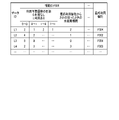
- FIG. 4 is a diagram showing an example of preprocessed learning log data.
- the data of the log for learning after the preprocessing shown in FIG. 4 is the data of the table in which the data of the extracted features is associated with the data ID of the data of each log acquired from the log database 12a.
- the feature data of the data ID L1 is the feature data extracted from the learning log data D11.
- the feature data includes, for example, the feature data of the log for each function ID such as the number of transitions of whether or not the function is used, the unused period when the usage history is traced back from the last use function, and the function ID of the last use function. Includes data.
- the number of transitions of whether or not to use a function is, for example, "0" for an item in which the function of the corresponding function ID is not used and "1" for an item in which the function of the corresponding function ID is used in a certain procedure.
- Information is "the number of transitions from 0 to 0", “the number of transitions from 0 to 1", “the number of transitions from 1 to 0", and "the number of transitions from 1 to 1".
- the preprocessing unit 112 refers to the log data and extracts each number of times. For example, in the case of data D11, the function of the function ID F001 is used in the first work item, and the function of the function ID F007 is used in the second work item.
- the preprocessing unit 112 adds 1 count to the “number of transitions from 1 to 0” of the function ID F001 of the data ID L1. Similarly, the preprocessing unit 112 extracts data on the number of transitions of whether or not the function is used up to the final procedure of the data D11.
- the unused period when the usage history is traced back from the last use function is information indicating how many items before the function of the corresponding function ID was used by tracing the usage history from the last use function.
- the preprocessing unit 112 refers to the log data and extracts the unused period when the usage history is traced back from the last usage function. For example, in the case of the data D11, the function of the function ID F001 is used two items before the usage history is traced back from the last usage function. Therefore, the preprocessing unit 112 sets the “unused period when the usage history is traced back from the last usage function” of the function ID F001 of the data ID L1 to 2.
- the function ID of the last-use function corresponds to the function ID of the function in the order to be predicted. That is, in the example, the final use function is the function to be predicted. If the functions in the order to be predicted are other than the last-use functions, the function IDs of the last-use functions in FIG. 4 are replaced with the function IDs in the corresponding order.
- the table in FIG. 4 is an example.
- the columns of the table can be set to any feature that seems optimal for predicting end-utilization features.
- the pretreatment unit 112 carries out the extraction process according to the characteristics.
- the design of the preprocessing unit 112 affects the prediction accuracy of the learning model 12b used in the prediction unit 113.
- the preprocessing applied at the time of learning by the prediction unit 113 and the preprocessing applied at the time of prediction may be basically the same.
- the data of the log for prediction does not include the data of the function ID of the final use function.
- the function ID of the final utilization function may be associated with the prediction log data.
- the data of the function ID of the final use function can also be extracted from the table of FIG. 4 regarding the data of the log for prediction.
- the prediction unit 113 calculates the prediction by inputting the feature data from the preprocessing unit 112 into the learning model 12b.
- the learning model 12b used in the prediction unit 113 may be any model that predicts, for example, the function ID of the final utilization function together with the prediction probability from the input feature data.
- the type of machine learning algorithm can also be mentioned.
- a decision tree is used as a learning model.
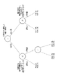
- FIG. 5 is an example of a decision tree used in the prediction unit 113.
- a decision tree is a learning model suitable for class classification, etc., which expresses a number of judgment paths and their judgment results in a tree structure.
- the prediction unit 113 makes a determination in order from the root node in the decision tree of FIG. 5 with respect to the input feature data, and outputs the function ID of the final utilization function together with the prediction probability.
- Various machine learning algorithms for generating decision trees include IterativeDichotomiser3 (ID3), C4.5, C5.0, Classification and RegressionTrees (CART), Chi-squared Automatic Interaction Detection (CHAID), etc. Algorithms can be used.
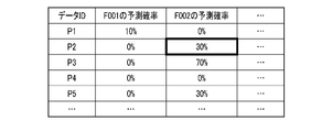
- FIG. 6A is a diagram showing an example of prediction result data.
- the prediction result data is, for example, a table including prediction probability data indicating the certainty of each function ID as a final use function for each data ID of the prediction log data. be.
- the filtering processing unit 114 performs filtering processing of log data for prediction so that the extraction processing unit can extract rare procedures.
- the filtering processing unit 114 determines whether or not the true function is the target function for each data ID of the log data for prediction.
- the true function is the last-use function actually used in the predictive log data. For example, if the predictive log data is created from log data for which the final use function of the procedure is known, the true function is recorded in the table of FIG. 4 because the actual final use function is clear. It may be the last-use function to be performed.
- the filtering processing unit 114 refers to the true utilization function table shown in FIG. 6B, so that the true utilization function is the target function. Whether or not it is determined for each data ID. In the example of FIG.
- the filtering processing unit 114 determines that the true utilization function is the target function for the data IDs P2, P3, and P4. At this time, the filtering processing unit 114 performs the following determination. On the other hand, for other data IDs, the filtering processing unit 114 turns off the flag. This flag is a flag indicating whether or not the target function to which the data of the log of the corresponding data ID is specified is a rare procedure that occurs as the final use function. When the flag is off, the data in the log for the corresponding data ID indicates that the specified target function is not a rare procedure that occurs as a last-use function.
- the filtering processing unit 114 is the prediction probability of the target function larger than zero and equal to or less than the threshold value for each data ID whose true utilization function is the target function in the table output from the prediction unit 113? Judge whether or not. Then, the filtering processing unit 114 turns on the flag for the data ID for which the prediction probability is determined to be equal to or less than the threshold value.
- the flag is on, the data in the log for the corresponding data ID indicates that the specified target function is a rare procedure that occurs as a last-use function. For example, when the function ID of the target function is the function ID F002 shown in FIG. 3A and the threshold value is 40% shown in FIG. 3B, the prediction probability of the function ID F002 is equal to or less than the threshold value for the data ID P2. It is judged.
- the two determinations in the filtering processing unit 114 may be performed in the reverse order. That is, the filtering processing unit 114 first selects the data ID whose prediction probability of the target function is greater than zero and equal to or less than the threshold value, and then whether or not the true utilization function of the selected data ID is the target function. May be determined.
- the extraction processing unit 115 extracts the data ID of the data of the log for prediction based on the determination result of the filtering processing unit 114. That is, the extraction processing unit 115 extracts the data ID for which the flag is turned on. Then, the extraction processing unit 115 generates the verification item data 3 of the rare procedure by adding the function ID of the target function to the position of the missing portion of the data in the log of the extracted data ID. For example, in the examples of FIGS. 6A and 6B, the function ID F002, which is the function ID of the target function, is added to the position of the missing portion of the data of the data ID P2.
- the data in the log of the data ID P2 includes, for example, the function IDs F002, F009, F005, F001, F002, F003, and the "missing portion" shown in FIG. 2B, the verification item of the rare procedure.
- the data 3 is data including the function IDs F002, F009, F005, F001, F002, F003, and "F002".
- the verification item data 3 generated in this way is, for example, data of a procedure that has not been used much in the past among the log data including the target function specified by the system user as the final use function, that is, the data of the rare procedure. Is.
- the extraction processing unit 115 may display the generated verification item data 3 of the rare procedure on, for example, a display provided in the management terminal 2.
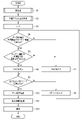
- FIG. 7 is a flowchart showing the operation of the rare procedure generation device 1 in the first embodiment.
- the process of FIG. 7 is executed by, for example, the processor 11.
- the learning model has been sufficiently trained in the processing of FIG. 7.
- step S1 the processor 11 preprocesses the data of the log for prediction. Then, the processor 11 generates the data of the table shown in FIG. 4, for example.
- step S2 the processor 11 calculates the prediction using the learning model 12b based on the table generated as a result of the preprocessing.
- step S3 the processor 11 initializes the index i to 0.
- the index i indicates the data of the log for prediction of the target of the filtering process. For example, when i is 0, it indicates that the data of the first data ID in the input data of the log for prediction is the target of the filtering process.
- step S4 the processor 11 refers to the true utilization function table and determines whether or not the true utilization function of the data of the prediction log corresponding to the index i is the target function.
- step S4 when it is determined that the true utilization function of the data of the prediction log corresponding to the index i is the target function, the process proceeds to step S5.
- step S7 when it is determined in step S4 that the true utilization function of the data of the prediction log corresponding to the index i is not the target function, the process proceeds to step S7.
- step S5 the processor 11 refers to the table of prediction results and determines whether or not the prediction probability of the target function among the prediction results corresponding to the index i is greater than zero and equal to or less than the threshold value.
- step S6 the process proceeds to step S6.
- step S5 when it is determined that the prediction probability of the target function among the prediction results corresponding to the index i is larger than zero and not equal to or less than the threshold value, the process proceeds to step S7.
- step S6 the processor 11 turns on the flag for the index i. After that, the process proceeds to step S8. As a result, it is determined that the log data corresponding to the index i is the verification item data of the rare procedure including the target function specified by the system user in the final use function, for example.
- step S7 the processor 11 turns off the flag for the index i. After that, the process proceeds to step S8. As a result, it is determined that the log data corresponding to the index i is not the verification item data of the rare procedure including the target function specified by the system user in the final use function, for example.
- step S9 the processor 11 increments the index i. After that, the process returns to step S4. In this case, the processor 11 performs a filtering process for the data of the log for the next prediction.
- step S10 the processor 11 extracts the data ID of the log for prediction for which the flag is turned on.
- step S11 the processor 11 generates a rare procedure by adding the function ID of the target function to the position of the missing portion of the data of each extracted data ID.
- step S12 the processor 11 displays a list of generated rare procedures on, for example, a display provided in the management terminal 2. After that, the process of FIG. 7 ends.
- step S12 the verification item data of the rare procedure may be simply transmitted to, for example, the management terminal 2.
- the learning model performs filtering processing based on the target function and the probability threshold value with respect to the predicted probability calculated based on the log representing the usage history of the function of the business system. Then, a rare procedure is generated based on the result of the filtering process.
- the filtering process extracts the function predicted in the prediction result as the target function and the function having a low prediction probability.
- a rare procedure of a function that a system user wants to verify can be generated while using conventional machine learning and a learning model generated by the conventional machine learning.
- the verification item when the verification item is generated, the verification item is designed under complex conditions such that the commercial log is not used as it is, but the target function is used after the procedure with some patterns. In some cases. In such a case, since the function used at the end of the procedure has not been determined, the same filtering process as in the first embodiment cannot be performed.
- the second embodiment is an embodiment corresponding to so-called unsupervised learning because learning is performed without using the correct information of the true utilization function.
- FIG. 8 is a diagram showing an example of a system including a rare procedure generator according to a second embodiment.
- the memory 14 shown in FIG. 8 includes the program 14a shown in FIG. 1, the target function data 14b, the probability threshold data 14c, the function table 14d used immediately before the prediction target, and the function transition rule table 14e.
- the function table 14d used immediately before the prediction target is a table that stores the function ID used immediately before the prediction target function in association with the data ID of the data of the prediction target. For example, if the missing part of the data of the log for prediction is the last use function, the function table 14d used immediately before the prediction target uses the function ID of the function used immediately before the last use function. It is stored in association with the data ID.
- the function transition rule table 14e is a table that can be used for each function ID immediately before the function of the function ID, that is, the function ID of the function that can be established as a procedure is associated and stored.
- the filtering processing unit 114 in the second embodiment performs filtering processing on the data of the log for prediction so as to exclude predictions that do not hold as a procedure.
- the filtering processing unit 114 reads the function that can be used before the target function from the function transition rule table 14e.
- the function ID of the target function is the function ID F002 shown in FIG. 3A.
- the filtering processing unit 114 reads the function ID of the function that can be used immediately before the function ID F002 from the function transition rule table 14e.
- the function IDs of the functions that can be used immediately before the function ID F002 are the function IDs F001, F007, and F009.
- the filtering processing unit 114 refers to the function table 14d used immediately before the prediction target, and the function actually used before the prediction target is a function that can be used before the target function.
- the data of the above is determined by the threshold value of the same prediction probability as in the first embodiment. For example, when the function table 14d used immediately before the prediction target is shown in FIG. 9B, the filtering processing unit 114 performs determination of the data IDs P2, P3, and P4 by the threshold value of the prediction probability. For example, when the prediction result is shown in FIG. 10 and the threshold value is 40% shown in FIG. 3B, the filtering processing unit 114 turns on the flag for the data in the log of the data ID P2.
- FIG. 11 is a flowchart showing the operation of the rare procedure generation device 1 in the second embodiment.
- the process of FIG. 11 is executed by, for example, the processor 11.
- the learning model is sufficiently trained in the processing of FIG. 11 as in the processing of FIG. 7.
- step S101 the processor 11 preprocesses the data of the log for prediction. Then, the processor 11 generates the data of the table shown in FIG. 4, for example. In the second embodiment, the table does not have to contain the data of the function ID of the last-utilized function.
- step S102 the processor 11 calculates a prediction using the learning model 12b based on the table generated as a result of the preprocessing.
- step S103 the processor 11 initializes the index i to 0.
- step S104 the processor 11 refers to the function table 14d and the function transition rule table 14e used immediately before the prediction target, and immediately before the prediction target of the data of the prediction log corresponding to the index i. It is determined whether or not the function used in is a function that can transition to the target function. When it is determined in step S104 that the function used immediately before the prediction target of the prediction log data corresponding to the index i is a function capable of transitioning to the target function, the process proceeds to step S105. On the other hand, when it is determined in step S104 that the function used immediately before the prediction target of the prediction log data corresponding to the index i is not a function capable of transitioning to the target function, the process proceeds to step S107. ..
- step S105 the processor 11 refers to the table of prediction results and determines whether or not the prediction probability of the target function among the prediction results corresponding to the index i is greater than zero and equal to or less than the threshold value.
- step S106 the process proceeds to step S106.
- step S107 the process proceeds to step S107.
- step S106 the processor 11 turns on the flag for the index i. After that, the process proceeds to step S108. As a result, it is determined that the log data corresponding to the index i is the verification item data of the rare procedure including the target function specified by the system user in the final use function, for example.
- step S107 the processor 11 turns off the flag for the index i. After that, the process proceeds to step S108. As a result, it is determined that the log data corresponding to the index i is not the verification item data of the rare procedure including the target function specified by the system user in the final use function, for example.
- step S109 the processor 11 increments the index i. After that, the process returns to step S104. In this case, the processor 11 performs a filtering process for the data of the log for the next prediction.
- step S110 the processor 11 extracts the data ID of the log for prediction for which the flag is turned on.
- step S111 the processor 11 generates a rare procedure by adding the function ID of the target function to the position of the missing portion of the data of each extracted data ID.
- step S112 the processor 11 displays a list of generated rare procedures on, for example, a display provided in the management terminal 2. After that, the process of FIG. 11 ends.
- step S112 the verification item data of the rare procedure may be simply transmitted to, for example, the management terminal 2.
- the memory of the rare procedure generation device 1 further stores the function table 14d and the function transition rule table 14e used immediately before the prediction target.
- the function table 14d used before the prediction target and the function transition rule table 14e instead of the true utilization function table, the function used at the end of the procedure and one of them. It is guaranteed that the transition with the previously used function is established. As a result, it can be expected that abnormal procedures (procedures that do not hold), which are a concern when functions with a low prediction probability are extracted without these filtering processes, are excluded.
- a rare procedure is generated in which the target functions that the system user wants to verify are used in a specific order.
- the rare procedure is simply generated as a simpler process, the filtering process based on the target function does not necessarily have to be performed.
- the procedure of the function is recorded as a log.
- the embodiment is not limited to this.
- the screen transition procedure may be recorded as a log instead of the function procedure.
- the customer's product purchase history may be recorded as a log.
- future purchase products for each customer can be predicted by the learning model. Then, by applying this technique, it is possible to predict in advance what products are purchased in what order by customers who purchase a certain product.
- the procedure of transition of data of any kind can be recorded as a log.
- the data of the log for prediction is said to be the data in which one of the usage procedures, for example, the last function ID is missing.
- the data of the log for prediction may be data in which the function IDs in the order of two or more of the usage procedures are missing.
- the learning model in this case may be a model that can correspond to a plurality of objective variables.
- a learning model that can accommodate such a plurality of objective variables can be constructed by, for example, a random forest or a neural network.
- the function IDs of the true utilization functions used in step S4 of the first embodiment may be set for each of the defective portions.
- step S104 of the second embodiment it is determined for each prediction target whether or not the function used immediately before the prediction target of the prediction log data is a function capable of transitioning to the target function. May be carried out. Further, in the comparison between the prediction probability and the probability threshold value in step S5 of the first embodiment or step S105 of the second embodiment, the prediction probabilities of all the two or more prediction targets are greater than zero and below the threshold value. At some point, the process may move to step S6 or S106, or when the prediction probability of any one of the two or more prediction targets is greater than zero and less than or equal to the threshold, the process moves to step S6 or S106. You may.
- the present invention is not limited to the above-described embodiment, and can be variously modified at the implementation stage without departing from the gist thereof.
- each embodiment may be carried out in combination as appropriate, in which case the combined effect can be obtained.
- the embodiments include various inventions, and various inventions can be extracted by a combination selected from a plurality of disclosed constituent requirements. For example, even if some constituent elements are deleted from all the constituent elements shown in the embodiment, if the problem can be solved and the effect is obtained, the configuration in which the constituent elements are deleted can be extracted as an invention.
Landscapes
- Engineering & Computer Science (AREA)
- Theoretical Computer Science (AREA)
- Physics & Mathematics (AREA)
- General Physics & Mathematics (AREA)
- General Engineering & Computer Science (AREA)
- Computing Systems (AREA)
- Evolutionary Computation (AREA)
- Data Mining & Analysis (AREA)
- Computational Linguistics (AREA)
- Mathematical Physics (AREA)
- Software Systems (AREA)
- Artificial Intelligence (AREA)
- Computer Hardware Design (AREA)
- Quality & Reliability (AREA)
- Debugging And Monitoring (AREA)
Abstract
希少手順生成装置は、予測部と、フィルタリング処理部と、抽出処理部とを備える。予測部は、複数の機能を有するシステムにおける機能の利用順序が記録されたログである学習用の第1のデータに基づいて機能の利用順序を学習した学習モデルを用いて、機能の利用順序のうちで一部の順序の機能が欠損しているログである予測用の第2のデータから、欠損している機能を予測確率とともに予測する。フィルタリング処理部は、予測確率がゼロよりも大きくて閾値以下であるか否かを判定する。抽出処理部は、フィルタリング処理部の判定結果に従って第2のデータを抽出する。
Description
実施形態は、例えばシステム開発において利用できる検証のための希少手順生成装置、希少手順生成方法及びプログラムに関する。
システム開発では、比較的早い工程のうちに、正常系動作及び頻発しやすい動作についての確認が一通り実施されていることが多い。このため、システム開発における後工程の検証では、準正常系動作及び希少な動作に的を絞って検証が実施されることがある。希少な動作の対象は、正常な動作及び手順を除くすべてのパターンである。つまり、希少な動作といっても対象は広い範囲にわたるので、検証すべき対象を選定することは一般には難しい。現在、検証項目は人手で策定されているので、非効率であるばかりか品質面でも考慮の余地がある。検証項目が膨大になり得る場合において、システムの利用履歴であるログを利用して検証項目を生成することが試みられている。
検証項目のシミュレーションに用いるために、開発対象システムの商用ログ等の様々な手順に関する情報が提供されている。しかしながら、一般に、商用ログ等に記録されている手順は膨大である。このため、希少な動作といっても全ての手順をトレースすることは困難である。したがって、希少な動作であっても何らかのパターン認識技術及び機械学習技術等を応用することで検証項目を生成することは有効である。
甘利俊一ら(著)、「パターン認識と学習の統計学」、岩波書店、2003年4月11日、p.20-23
Joel Grus(著)、菊池 彰(訳)、「ゼロからはじめるデータサイエンス-Pythonで学ぶ基本と実践」、株式会社オライリー・ジャパン、2017年1月27日、p.233-246
実施形態は、検証のための希少手順を商用ログから抽出することができる技術を提供しようとするものである。
一態様の希少手順生成装置は、予測部と、フィルタリング処理部と、抽出処理部とを備える。予測部は、複数の機能を有するシステムにおける機能の利用順序が記録されたログである学習用の第1のデータに基づいて機能の利用順序を学習した学習モデルを用いて、機能の利用順序のうちで一部の順序の機能が欠損しているログである予測用の第2のデータから、欠損している機能を予測確率とともに予測する。フィルタリング処理部は、予測確率がゼロよりも大きくて閾値以下であるか否かを判定する。抽出処理部は、フィルタリング処理部の判定結果に従って第2のデータを抽出する。
実施形態によれば、検証のための希少手順を商用ログから抽出することができる技術を提供することができる。
以下、図面を参照して実施形態を説明する。各実施形態では、例えば業務システムに実装される機能の検証のための検証項目のうち、希少な手順である希少手順についての検証項目が生成される。希少手順は、業務システムに実装された複数の機能の利用順序のうち、希な順序で機能が遷移する手順である。例えば、実施形態では、検証したい機能が予め設定されていて、その機能を含む一連の利用手順のうちの希少手順がログを用いて抽出される。ログは、業務システムに実装された機能の利用履歴としても理解され得る。したがって、例えば、複数の機能の利用手順のそれぞれが、ログとして定義され得る。業務システム4によっては、同一の機能が繰り返して利用されることもある。
実施形態では、過去に蓄積されたログを学習させることによって複数の機能の利用手順を予測する学習モデルが形成される。一方、実施形態では学習で用いられたログとは別に手順の一部に欠損のあるログが用意され、そのログが学習済みの学習モデルに適用されることで、欠損の位置の機能が予測される。この予測された機能の予測確率が低いものが希少手順に該当する。
以降、手順の最後に利用される機能である最終利用機能を欠損箇所とした例を用いて説明する。ここで、第1の実施形態では、手順の最終利用機能が分かっているログのデータを用いての希少手順の生成が説明される。一方、第2の実施形態では、手順の最終利用機能が分からないログのデータを用いての希少手順の生成が説明される。
第1の実施形態において想定される状況は、ログの一部がそのまま検証に用いられる状況である。一方、第2の実施形態において想定される状況は、特定の手順の後にシステムユーザが検証対象としたいターゲット機能が実施されるような、複合的な条件で検証項目がデザインされる状況である。
[第1の実施形態]
(構成)
図1は、第1の実施形態に係る希少手順生成装置を含むシステムの一例を示す図である。図1において、希少手順生成装置1は、例えば業務システム4に実装されたアプリケーション5を検証するための検証項目を生成する。業務システム4に備わる機能は、主にアプリケーション5によって提供される。アプリケーション5の開発が継続されることにより、業務システム4には新規機能がインプリメントされ得る。
(構成)
図1は、第1の実施形態に係る希少手順生成装置を含むシステムの一例を示す図である。図1において、希少手順生成装置1は、例えば業務システム4に実装されたアプリケーション5を検証するための検証項目を生成する。業務システム4に備わる機能は、主にアプリケーション5によって提供される。アプリケーション5の開発が継続されることにより、業務システム4には新規機能がインプリメントされ得る。
業務システム4に新規機能が導入されると、バグフィックスを含め、システムの実稼働前に検証作業が行われ得る。前述したように、実施形態では、検証作業に用いられる検証項目のうち、希少手順に係る検証項目が生成され得る。
図1において、希少手順生成装置1は、プロセッサ11、ストレージ12、インタフェース部13及びメモリ14を備える。希少手順生成装置1は、コンピュータであり、例えば、パーソナルコンピュータ或いはサーバコンピュータ等として実現される。
インタフェース部13は、ネットワーク100に接続され、同様にネットワーク100に接続された管理端末2を介して、業務システム4との間で各種のデータを授受し得る。
ストレージ12は、例えば、HDD(Hard Disk Drive)及びSSD(Solid State Drive)等の、不揮発性の記憶媒体(ブロックデバイス)である。ストレージ12は、OS(Operating System)及びデバイスドライバ等の基本プログラム並びに希少手順生成装置1の機能を実現させるためのプログラム等に加えて、ログデータベース12aを記憶する。また、ストレージ12は、学習モデル12bを記憶する。
図2A及び図2Bは、ログデータベース12aに蓄積されるログのデータの一例を示す図である。ログデータベース12aに蓄積されるログのデータは、学習用のログのデータと予測用のログのデータとを含む。図2Aは学習用のログのデータの一例を示す図であり、図2Bは予測用のログのデータの一例を示す図である。
図2Aに示されるように、学習用のログのデータは、機能IDと、時系列情報とを関連付けて記憶するテーブルのデータである。機能IDは、業務システム4の機能毎に一意に割り当てられた機能の識別子のデータである。時系列情報は、対応する機能IDの機能が実際に利用された日時のデータである。1つのログのデータでは、業務システム4の特定の動作について最初に利用された機能の機能IDから最後に利用された機能である最終利用機能までの機能IDがその利用日時とともに時系列順に記録される。例えば、データD11は、業務システム4のある動作について7個の機能が利用され、最初に利用された機能が機能ID F001の機能であり、最終利用機能が機能ID F004の機能であることを示している。ここで、手順のなかの項目である機能IDの数、すなわち機能の数は任意の数であってよい。また、1つの動作について利用される機能の数も7に限るものではない。
図2Bに示されるように、予測用のログのデータは、学習用のログのデータのうち、一部の手順の機能の機能IDが欠損しているデータである。例えば、データD21は、最終利用機能の機能IDが欠損しているデータである。実施形態では、欠損している機能IDが予測対象の機能IDになり得る。このような予測用のログのデータは、学習用のログのデータの一部を欠損させることで生成されてよい。ここで、予測用のログのデータにおける機能IDは、学習用のログのデータにおける機能IDと共通である。一方、予測用のログのデータにおける時系列情報は、業務システム4の特定の動作が利用される予定の日時である。予測用のログのデータにおいて機能IDが欠損している位置は、希少手順生成装置1のシステムユーザによって任意に決められてよい。
学習用のログのデータ及び予測用のログのデータは、機能ID及び時系列情報以外のデータを含み得る。例えば、図では示されていないが、それぞれの学習用のログのデータ及びそれぞれの予測用のログのデータには、固有のデータIDが関連付けられる。
また、学習用のログのデータは、例えば、アプリケーション5のログ収集機能や、業務システム4に接続された管理端末2により継続的に収集される。収集されたログは、前述したようにしてログデータベース12aとして記憶される他に、プライバシー情報が除かれた上で例えば記憶媒体6に記録され得る。あるいは、ログは、例えばキーバリュー型、SQL型、あるいはNoSQL型のデータベースに蓄積され、クラウドを介して提供されてもよい。要するに、ログは、希少手順生成装置1からアクセスできるのであればどのようなものでもよい。
メモリ14は、例えばRAM(Random Access Memory)を含む。メモリ14は、ストレージ12からロードされたプログラム14aに加え、ターゲット機能データ14b及び確率閾値データ14cを記憶する。
図3Aは、ターゲット機能データ14bの一例を示す図である。ターゲット機能データ14bは、システムユーザが検証対象としたいターゲット機能の機能IDを含むデータである。図3Aでは、機能ID F002が今回のターゲット機能であることが示されている。ターゲット機能データ14bとしての機能IDは、例えばシステムユーザによって任意に設定され得る。
図3Bは、確率閾値データ14cの一例を示す図である。確率閾値データ14cは、機能の発生の希少度を判定するための機能の予測確率の閾値のデータである。確率閾値データ14cは、例えば百分率で表される。後で説明する予測において、予測される機能の予測確率がゼロよりも大きくて閾値以下である機能を含む手順は希少手順であると判定される。確率閾値データ14cとしての閾値は、例えばシステムユーザによって任意に設定され得る。
プロセッサ11は、例えばCentral Processing Unit(CPU)、Micro Processing Unit(MPU)等の演算ユニットであり、メモリ14にロードされたプログラムに従って各種の処理を実施する。ここで、プロセッサ11は、単体のCPU等で構成されていてもよいし、複数のCPU等で構成されていてもよい。
プロセッサ11は、プログラム14aに含まれる命令を実行することにより、取得部111、前処理部112、予測部113、フィルタリング処理部114及び抽出処理部115として動作し得る。プログラム14aは、ストレージ12に記憶されていなくてもよく、光学メディア等の別の記録媒体に記録されていてもよいし、ネットワーク100を通して提供されてもよい。また、取得部111、前処理部112、予測部113、フィルタリング処理部114及び抽出処理部115は、同様の動作を実現する専用のハードウェアによって実現されてもよい。
取得部111は、ログのデータをログデータベース12aから取得し、前処理部112に送る。ここでのログのデータは、学習用のログのデータと予測用のログのデータの双方を含む。
前処理部112は、取得されたログのデータに対して前処理を実施する。前処理では、予測部113による機械学習及び予測に利用され得る特徴が、ログデータベース12aから取得されるログのデータから抽出される。図4は、前処理された学習用のログのデータの一例を示す図である。
図4に示す前処理後の学習用のログのデータは、ログデータベース12aから取得されるそれぞれのログのデータのデータIDに、抽出された特徴のデータが関連付けられているテーブルのデータである。例えば、データID L1の特徴のデータは、学習用のログのデータD11から抽出された特徴のデータであることを示す。
特徴のデータは、例えば、機能の利用の有無の遷移の回数、利用履歴を最終利用機能からさかのぼったときの未使用期間といった機能ID毎のログの特徴のデータと、最終利用機能の機能IDのデータとを含む。
機能の利用の有無の遷移の回数は、例えば、ある手順のなかで、対応する機能IDの機能が利用されていない項目を“0”、利用された項目を“1”としたときの、“0から0への遷移の回数”、“0から1への遷移の回数”、“1から0への遷移の回数”、“1から1への遷移の回数”の情報である。前処理部112は、ログのデータを参照してそれぞれの回数を抽出する。例えば、データD11の場合、1つ目の作業項目で機能ID F001の機能が利用され、2つ目の作業項目で機能ID F007の機能が利用されている。したがって、前処理部112は、データID L1の機能ID F001の“1から0への遷移の回数”に1カウントを加える。同様にして前処理部112は、データD11の最後の手順までの機能の利用の有無の遷移の回数のデータの抽出を実施する。
利用履歴を最終利用機能からさかのぼったときの未使用期間は、対応する機能IDの機能が利用履歴を最終利用機能からさかのぼって何項目前に利用されたかを示す情報である。前処理部112は、ログのデータを参照して利用履歴を最終利用機能からさかのぼったときの未使用期間を抽出する。例えば、データD11の場合、利用履歴を最終利用機能からさかのぼった2項目前に機能ID F001の機能が利用されている。したがって、前処理部112は、データID L1の機能ID F001の“利用履歴を最終利用機能からさかのぼったときの未使用期間”を2とする。
最終利用機能の機能IDは、予測対象としたい順序の機能の機能IDに対応している。つまり、例では最終利用機能が予測対象の機能である。予測対象としたい順序の機能が最終利用機能以外であれば、図4の最終利用機能の機能IDは対応する順序における機能IDに置き換えられる。
ここで、図4のテーブルは一例である。テーブルのカラムは、最終利用機能を予測するために最適だと思われる任意の特徴が設定され得る。この場合において、前処理部112は、特徴に応じた抽出処理を実施する。前処理部112の設計によって予測部113で利用される学習モデル12bの予測精度が左右される。
また、予測部113による学習時に適用される前処理と予測時に適用される前処理とは基本的に同じでよい。ここで、図2Bで示したように、予測用のログのデータは、最終利用機能の機能IDのデータを含まない。しかしながら、例えば予測用のログのデータが、手順の最終利用機能が分かっているログのデータから作成される場合には、予測用のログのデータに最終利用機能の機能IDが関連付けられ得る。この場合、予測用のログのデータについての図4のテーブルにおいても最終利用機能の機能IDのデータが抽出され得る。
予測部113は、前処理部112からの特徴のデータを学習モデル12bに入力することで予測を算出する。予測部113において用いられる学習モデル12bは、入力された特徴のデータから、例えば最終利用機能の機能IDをその予測確率とともに予測する任意のモデルであってよい。ただし、学習モデル12bの予測精度を左右する要素として、前述した特徴の選定に加えて、機械学習のアルゴリズムの種別も挙げられる。実施形態においては、学習モデルとして例えば決定木が用いられる。図5は、予測部113において用いられる決定木の一例である。決定木は、いくつもの判断経路とその判断結果とを木構造で表現したもので、クラスの分類等に適した学習モデルである。予測部113は、入力された特徴のデータに対し、図5の決定木における根のノードから順に判定を実施し、最終利用機能の機能IDをその予測確率とともに出力する。決定木を生成するための機械学習のアルゴリズムとしては、Iterative Dichotomiser 3(ID3)、C4.5、C5.0、Classification and Regression Trees(CART)、Chi-squared Automatic Interaction Detection(CHAID)等の種々のアルゴリズムが用いられ得る。
図6Aは、予測結果のデータの一例を示す図である。図6Aに示されるように、予測結果のデータは、例えば、予測用のログのデータのデータID毎の、それぞれの機能IDの最終利用機能としての確からしさを示す予測確率のデータを含むテーブルである。
フィルタリング処理部114は、抽出処理部において希少手順を抽出できるように、予測用のログのデータのフィルタリング処理をする。
まず、フィルタリング処理部114は、それぞれの予測用のログのデータのデータID毎に、真の機能がターゲット機能であるか否かを判定する。真の機能は、予測用のログのデータにおいて実際に利用された最終利用機能である。例えば予測用のログのデータが手順の最終利用機能が分かっているログのデータから作成される場合には、実際に利用された最終利用機能が明らかなので、真の機能は図4のテーブルにおいて記録される最終利用機能であってよい。例えば、ターゲット機能の機能IDが図3Aで示した機能ID F002であるとき、フィルタリング処理部114は、図6Bで示す真の利用機能テーブルを参照することで、真の利用機能がターゲット機能であるか否かをデータID毎に判定する。図6Bの例では、データID P2、P3、P4については真の利用機能がターゲット機能であると判定される。このとき、フィルタリング処理部114は、次の判定を実施する。一方、これ以外のデータIDについては、フィルタリング処理部114は、フラグをオフにする。このフラグは、対応するデータIDのログのデータが指定されたターゲット機能が最終利用機能として発生する希少手順であるか否かを示すフラグである。フラグがオフであるとき、対応するデータIDのログのデータは、指定されたターゲット機能が最終利用機能として発生する希少手順でないことを示す。
また、フィルタリング処理部114は、予測部113から出力されたテーブルのうちの、真の利用機能がターゲット機能であるデータID毎に、ターゲット機能の予測確率がゼロよりも大きくて閾値以下であるか否かを判定する。そして、フィルタリング処理部114は、予測確率が閾値以下であると判定されたデータIDについてのフラグをオンにする。フラグがオンであるとき、対応するデータIDのログのデータは、指定されたターゲット機能が最終利用機能として発生する希少手順であることを示す。例えば、ターゲット機能の機能IDが図3Aで示した機能ID F002であり、閾値が図3Bで示した40%であるとき、データID P2については、機能ID F002の予測確率が閾値以下であると判定される。
ここで、フィルタリング処理部114における2つの判定は、逆順で行われてもよい。つまり、フィルタリング処理部114は、最初にターゲット機能の予測確率がゼロよりも大きくて閾値以下であるデータIDを選別した後で、選別したデータIDの真の利用機能がターゲット機能であるか否かを判定してもよい。
抽出処理部115は、フィルタリング処理部114の判定結果に基づいて予測用のログのデータのデータIDを抽出する。つまり、抽出処理部115は、フラグがオンされているデータIDを抽出する。そして、抽出処理部115は、抽出したデータIDのログのデータの欠損部分の位置にターゲット機能の機能IDを追加することで希少手順の検証項目データ3を生成する。例えば、図6A及び図6Bの例では、データID P2のデータの欠損部分の位置にターゲット機能の機能IDである機能ID F002が追加される。具体的には、データID P2のログのデータが例えば図2Bで示した機能ID F002、F009、F005、F001、F002、F003、“欠損部分”を含むデータであるとすると、希少手順の検証項目データ3は、機能ID F002、F009、F005、F001、F002、F003、“F002”を含むデータになる。このようにして生成される検証項目データ3は、例えばシステムユーザによって指定されたターゲット機能を最終利用機能として含むログのデータのうちでも過去にあまり利用されたことがない手順、すなわち希少手順のデータである。なお、抽出処理部115は、生成した希少手順の検証項目データ3を、例えば管理端末2に設けられるディスプレイに表示させてもよい。
(動作)
次に、第1の実施形態における希少手順生成装置1の動作を説明する。図7は、第1の実施形態における希少手順生成装置1の動作を示すフローチャートである。図7の処理は、例えばプロセッサ11によって実行される。ここで、図7の処理に際して、学習モデルの学習は十分に行われているものとする。
次に、第1の実施形態における希少手順生成装置1の動作を説明する。図7は、第1の実施形態における希少手順生成装置1の動作を示すフローチャートである。図7の処理は、例えばプロセッサ11によって実行される。ここで、図7の処理に際して、学習モデルの学習は十分に行われているものとする。
図7の処理は、予測用のログのデータがプロセッサ11に入力されたときに開始される。ステップS1において、プロセッサ11は、予測用のログのデータに対する前処理をする。そして、プロセッサ11は、例えば図4で示したテーブルのデータを生成する。
ステップS2において、プロセッサ11は、前処理の結果として生成されたテーブルに基づいて学習モデル12bを用いて予測を算出する。
ステップS3において、プロセッサ11は、インデックスiを0に初期化する。インデックスiは、フィルタリング処理の対象の予測用のログのデータを示す。例えば、iが0であるとき、入力された予測用のログのデータにおける先頭のデータIDのデータがフィルタリング処理の対象であることを示している。
ステップS4において、プロセッサ11は、真の利用機能テーブルを参照し、インデックスiに対応する予測用のログのデータの真の利用機能がターゲット機能であるか否かを判定する。ステップS4において、インデックスiに対応する予測用のログのデータの真の利用機能がターゲット機能であると判定されたときには、処理はステップS5に移行する。一方、ステップS4において、インデックスiに対応する予測用のログのデータの真の利用機能がターゲット機能でないと判定されたときには、処理はステップS7に移行する。
ステップS5において、プロセッサ11は、予測結果のテーブルを参照し、インデックスiに対応する予測結果のうちのターゲット機能の予測確率がゼロよりも大きくて閾値以下であるか否かを判定する。ステップS5において、インデックスiに対応する予測結果のうちのターゲット機能の予測確率がゼロよりも大きくて閾値以下であると判定されたときには、処理はステップS6に移行する。ステップS5において、インデックスiに対応する予測結果のうちのターゲット機能の予測確率がゼロよりも大きくて閾値以下でないと判定されたときには、処理はステップS7に移行する。
ステップS6において、プロセッサ11は、インデックスiについてのフラグをオンにする。その後、処理はステップS8に移行する。これにより、インデックスiに対応するログのデータは、例えばシステムユーザによって指定されたターゲット機能を最終利用機能に含む希少手順の検証項目データであると判定される。
ステップS7において、プロセッサ11は、インデックスiについてのフラグをオフにする。その後、処理はステップS8に移行する。これにより、インデックスiに対応するログのデータは、例えばシステムユーザによって指定されたターゲット機能を最終利用機能に含む希少手順の検証項目データでないと判定される。
ステップS8において、プロセッサ11は、すべての予測用のログのデータについてのフィルタリング処理が完了したか否かを判定する。例えば予測用のログのデータ数をNとしたとき、i=N-1であればすべての予測用のログのデータについてのフィルタリング処理が完了したと判定される。ステップS8において、すべての予測用のログのデータについてのフィルタリング処理が完了していないと判定されたときには、処理はステップS9に移行する。ステップS8において、すべての予測用のログのデータについてのフィルタリング処理が完了したと判定されたときには、処理はステップS10に移行する。
ステップS9において、プロセッサ11は、インデックスiをインクリメントする。その後、処理は、ステップS4に戻る。この場合、プロセッサ11は、次の予測用のログのデータについてのフィルタリング処理を行う。
ステップS10において、プロセッサ11は、フラグがオンになっている予測用のログのデータIDを抽出する。
ステップS11において、プロセッサ11は、抽出したそれぞれのデータIDのデータの欠損部分の位置にターゲット機能の機能IDを追加することによって希少手順を生成する。
ステップS12において、プロセッサ11は、生成した希少手順の一覧を例えば管理端末2に設けられるディスプレイに表示させる。その後、図7の処理は終了する。ステップS12においては、希少手順の検証項目データが例えば管理端末2に送信されるだけでもよい。
(効果)
以上説明したように第1の実施形態では、学習モデルが業務システムの機能の利用履歴を表すログに基づいて算出した予測確率に対し、ターゲット機能及び確率閾値に基づいてフィルタリング処理が行われる。そして、フィルタリング処理の結果に基づいて希少手順が生成される。
以上説明したように第1の実施形態では、学習モデルが業務システムの機能の利用履歴を表すログに基づいて算出した予測確率に対し、ターゲット機能及び確率閾値に基づいてフィルタリング処理が行われる。そして、フィルタリング処理の結果に基づいて希少手順が生成される。
例えば、従来の機械学習及びそれにより生成された学習モデルは、最も予測確率の高い項目を出力することを目的としている。したがって、従来の機械学習及びそれにより生成された学習モデルによって予測確率の低い希少手順を抽出することは単純にはできない。これに対し、第1の実施形態によれば、フィルタリング処理により、予測結果のうちで予測された機能がターゲット機能であり、かつ、予測確率の低い機能が抽出される。これにより、従来の機械学習及びそれにより生成された学習モデルが用いられつつも、例えばシステムユーザが検証したい機能の希少手順が生成され得る。
[第2の実施形態]
次に、第1の実施形態では、商用ログが用いられるような場合、つまり、例えば手順の最後に利用される機能が分かっている場合において、予測確率は低いが実際に最後にターゲット機能が利用される手順が抽出される。つまり、第1の実施形態では、真の利用機能が既知であるため、手順として成り立つ希少手順の検証項目データが生成され得る。このような第1の実施形態は、最後に実施される機能という正解の情報を利用して学習が行われる形態であり、いわゆる教師あり学習に相当する実施形態である。
次に、第1の実施形態では、商用ログが用いられるような場合、つまり、例えば手順の最後に利用される機能が分かっている場合において、予測確率は低いが実際に最後にターゲット機能が利用される手順が抽出される。つまり、第1の実施形態では、真の利用機能が既知であるため、手順として成り立つ希少手順の検証項目データが生成され得る。このような第1の実施形態は、最後に実施される機能という正解の情報を利用して学習が行われる形態であり、いわゆる教師あり学習に相当する実施形態である。
しかし、検証項目が生成されるときに、商用ログがそのまま用いられるのではなく、いくつかのパターンをもつ手順の後にターゲット機能が利用されるような、複合的な条件で検証項目がデザインされる場合もあり得る。このような場合では、手順の最後に利用される機能が確定していないので、第1の実施形態と同様のフィルタリング処理は実施され得ない。第2の実施形態は、真の利用機能という正解の情報が利用されずに学習が行われる形態なので、いわゆる教師なし学習に相当する実施形態である。
(構成)
図8は、第2の実施形態に係る希少手順生成装置を含むシステムの一例を示す図である。図8に示されるメモリ14は、図1に示されるプログラム14a、ターゲット機能データ14b及び確率閾値データ14cに加えて、予測対象の1つ前に利用された機能テーブル14dと、機能遷移則テーブル14eとを記憶している。予測対象の1つ前に利用された機能テーブル14dは、予測対象の機能の1つ前に利用された機能IDを予測用のログのデータのデータIDと関連付けて記憶するテーブルである。例えば、予測用のログのデータの欠損部分が最終利用機能であれば、予測対象の1つ前に利用された機能テーブル14dは、最終利用機能の1つ前に利用された機能の機能IDをデータIDと関連付けて記憶している。機能遷移則テーブル14eは、機能ID毎に、その機能IDの機能の1つ前に利用することができる、つまり手順として成立し得る機能の機能IDを関連付けて記憶するテーブルである。
図8は、第2の実施形態に係る希少手順生成装置を含むシステムの一例を示す図である。図8に示されるメモリ14は、図1に示されるプログラム14a、ターゲット機能データ14b及び確率閾値データ14cに加えて、予測対象の1つ前に利用された機能テーブル14dと、機能遷移則テーブル14eとを記憶している。予測対象の1つ前に利用された機能テーブル14dは、予測対象の機能の1つ前に利用された機能IDを予測用のログのデータのデータIDと関連付けて記憶するテーブルである。例えば、予測用のログのデータの欠損部分が最終利用機能であれば、予測対象の1つ前に利用された機能テーブル14dは、最終利用機能の1つ前に利用された機能の機能IDをデータIDと関連付けて記憶している。機能遷移則テーブル14eは、機能ID毎に、その機能IDの機能の1つ前に利用することができる、つまり手順として成立し得る機能の機能IDを関連付けて記憶するテーブルである。
第2の実施形態におけるフィルタリング処理部114は、手順として成立しないような予測を排除するように予測用のログのデータに対してフィルタリング処理を実施する。
まず、フィルタリング処理部114は、ターゲット機能の前に利用できる機能を、機能遷移則テーブル14eから読み取る。例えば、ターゲット機能の機能IDが図3Aで示した機能ID F002であるとする。この場合、フィルタリング処理部114は、機能ID F002の1つ前に利用できる機能の機能IDを機能遷移則テーブル14eから読み取る。例えば、機能遷移則テーブル14eが図9Aで示すものであるとき、機能ID F002の1つ前に利用できる機能の機能IDは、機能ID F001、F007、F009の3つである。そして、フィルタリング処理部114は、予測対象の1つ前に利用された機能テーブル14dを参照し、実際に予測対象の1つ前に利用された機能がターゲット機能の前に利用できる機能であるログのデータに対して第1の実施形態と同じ予測確率の閾値による判定を実施する。例えば、予測対象の1つ前に利用された機能テーブル14dが図9Bで示すものであるとき、フィルタリング処理部114は、データID P2、P3、P4について予測確率の閾値による判定を実施する。例えば、予測結果が図10で示すものであり、閾値が図3Bで示した40%であるとき、フィルタリング処理部114は、データID P2のログのデータについてのフラグをオンにする。
(動作)
次に、第2の実施形態における希少手順生成装置1の動作を説明する。図11は、第2の実施形態における希少手順生成装置1の動作を示すフローチャートである。図11の処理は、例えばプロセッサ11によって実行される。ここで、図7の処理と同様に、図11の処理に際しても、学習モデルの学習は十分に行われているものとする。
次に、第2の実施形態における希少手順生成装置1の動作を説明する。図11は、第2の実施形態における希少手順生成装置1の動作を示すフローチャートである。図11の処理は、例えばプロセッサ11によって実行される。ここで、図7の処理と同様に、図11の処理に際しても、学習モデルの学習は十分に行われているものとする。
図11の処理は、予測用のログのデータがプロセッサ11に入力されたときに開始される。ステップS101において、プロセッサ11は、予測用のログのデータに対する前処理をする。そして、プロセッサ11は、例えば図4で示したテーブルのデータを生成する。第2の実施形態においては、テーブルは、最終利用機能の機能IDのデータを含んでいなくてよい。
ステップS102において、プロセッサ11は、前処理の結果として生成されたテーブルに基づいて学習モデル12bを用いて予測を算出する。
ステップS103において、プロセッサ11は、インデックスiを0に初期化する。
ステップS104において、プロセッサ11は、予測対象の1つ前に利用された機能テーブル14dと機能遷移則テーブル14eとを参照し、インデックスiに対応する予測用のログのデータの予測対象の1つ前に利用された機能がターゲット機能に遷移できる機能であるか否かを判定する。ステップS104において、インデックスiに対応する予測用のログのデータの予測対象の1つ前に利用された機能がターゲット機能に遷移できる機能であると判定されたときには、処理はステップS105に移行する。一方、ステップS104において、インデックスiに対応する予測用のログのデータの予測対象の1つ前に利用された機能がターゲット機能に遷移できる機能でないと判定されたときには、処理はステップS107に移行する。
ステップS105において、プロセッサ11は、予測結果のテーブルを参照し、インデックスiに対応する予測結果のうちのターゲット機能の予測確率がゼロよりも大きくて閾値以下であるか否かを判定する。ステップS105において、インデックスiに対応する予測結果のうちのターゲット機能の予測確率がゼロよりも大きくて閾値以下であると判定されたときには、処理はステップS106に移行する。ステップS105において、インデックスiに対応する予測結果のうちのターゲット機能の予測確率がゼロよりも大きくて閾値以下でないと判定されたときには、処理はステップS107に移行する。
ステップS106において、プロセッサ11は、インデックスiについてのフラグをオンにする。その後、処理はステップS108に移行する。これにより、インデックスiに対応するログのデータは、例えばシステムユーザによって指定されたターゲット機能を最終利用機能に含む希少手順の検証項目データであると判定される。
ステップS107において、プロセッサ11は、インデックスiについてのフラグをオフにする。その後、処理はステップS108に移行する。これにより、インデックスiに対応するログのデータは、例えばシステムユーザによって指定されたターゲット機能を最終利用機能に含む希少手順の検証項目データでないと判定される。
ステップS108において、プロセッサ11は、すべての予測用のログのデータについてのフィルタリング処理が完了したか否かを判定する。例えば予測用のログのデータ数をNとしたとき、i=N―1であればすべての予測用のログのデータについてのフィルタリング処理が完了したと判定される。ステップS108において、すべての予測用のログのデータについてのフィルタリング処理が完了していないと判定されたときには、処理はステップS109に移行する。ステップS108において、すべての予測用のログのデータについてのフィルタリング処理が完了したと判定されたときには、処理はステップS110に移行する。
ステップS109において、プロセッサ11は、インデックスiをインクリメントする。その後、処理は、ステップS104に戻る。この場合、プロセッサ11は、次の予測用のログのデータについてのフィルタリング処理を行う。
ステップS110において、プロセッサ11は、フラグがオンになっている予測用のログのデータIDを抽出する。
ステップS111において、プロセッサ11は、抽出したそれぞれのデータIDのデータの欠損部分の位置にターゲット機能の機能IDを追加することによって希少手順を生成する。
ステップS112において、プロセッサ11は、生成した希少手順の一覧を例えば管理端末2に設けられるディスプレイに表示させる。その後、図11の処理は終了する。ステップS112においては、希少手順の検証項目データが例えば管理端末2に送信されるだけでもよい。
(効果)
以上説明したように第2の実施形態では、希少手順生成装置1のメモリは、予測対象の1つ前に利用された機能テーブル14dと機能遷移則テーブル14eとをさらに記憶している。真の利用機能テーブルに代えて予測対象の1つ前に利用された機能テーブル14dと機能遷移則テーブル14eとに基づくフィルタリング処理が実施されることで、手順の最後に利用される機能とそのひとつ前に利用される機能との間での遷移が成立することが担保される。これにより、これらのフィルタリング処理なしに予測確率の低い機能が抽出されたときに懸念される、異常系手順(成立しない手順)が除外されることが期待できる。
以上説明したように第2の実施形態では、希少手順生成装置1のメモリは、予測対象の1つ前に利用された機能テーブル14dと機能遷移則テーブル14eとをさらに記憶している。真の利用機能テーブルに代えて予測対象の1つ前に利用された機能テーブル14dと機能遷移則テーブル14eとに基づくフィルタリング処理が実施されることで、手順の最後に利用される機能とそのひとつ前に利用される機能との間での遷移が成立することが担保される。これにより、これらのフィルタリング処理なしに予測確率の低い機能が抽出されたときに懸念される、異常系手順(成立しない手順)が除外されることが期待できる。
(その他の変形例)
第1の実施形態及び第2の実施形態では、例えばシステムユーザが検証したいターゲット機能が特定の順序で利用される希少手順が生成される。これに対し、より簡易的な処理として単純に希少手順が生成されればよいのであれば、必ずしもターゲット機能に基づくフィルタリング処理は実施されなくてもよい。
第1の実施形態及び第2の実施形態では、例えばシステムユーザが検証したいターゲット機能が特定の順序で利用される希少手順が生成される。これに対し、より簡易的な処理として単純に希少手順が生成されればよいのであれば、必ずしもターゲット機能に基づくフィルタリング処理は実施されなくてもよい。
また、第1の実施形態及び第2の実施形態では、機能の手順をログとして記録することが想定されている。しかしながら、実施形態はこれに限らない。例えば機能の手順に代えて画面遷移の手順がログとして記録されてよい。また、機能の手順に代えて顧客の商品購買履歴がログとして記録されてもよい。この場合、顧客毎の将来の購入商品が学習モデルによって予測され得る。そして、この技術を応用すれば、ある商品を購入する顧客が事前にどんな商品をどんな順序で購入しているかが予測され得る。この他、実施形態では、あらゆる種別のデータの遷移の手順がログとして記録され得る。
また、第1の実施形態及び第2の実施形態では、予測用のログのデータは、利用手順のうちの1つの順序、例えば最後の機能IDが欠損しているデータであるとされている。これに対し、学習モデルによっては、予測用のログのデータは、利用手順のうちの2つ以上の順序の機能IDが欠損しているデータであってもよい。この場合の学習モデルは、複数の目的変数に対応できるモデルであればよい。このような複数の目的変数に対応できる学習モデルは、例えばランダムフォレスト、ニューラルネットワークによって構築され得る。なお、予測対象の機能IDが2つ以上である場合、第1の実施形態のステップS4において用いられる真の利用機能の機能IDは欠損箇所のそれぞれに対して設定されていてもよい。また、第2の実施形態のステップS104における予測用のログのデータの予測対象の1つ前に利用された機能がターゲット機能に遷移できる機能であるか否かの判定はそれぞれの予測対象に対して実施されてもよい。さらに、第1の実施形態のステップS5又は第2の実施形態のステップS105における予測確率と確率閾値との比較では、2つ以上の予測対象のすべての予測確率がゼロよりも大きくて閾値以下であるときに処理がステップS6又はS106に移行してもよいし、2つ以上の予測対象の何れか1つの予測確率がゼロよりも大きくて閾値以下であるときに処理がステップS6又はS106に移行してもよい。
さらに、本発明は、前述した実施形態に限定されるものではなく、実施段階ではその要旨を逸脱しない範囲で種々に変形することができる。また、各実施形態は適宜組み合わせて実施してもよく、その場合組み合わせた効果が得られる。更に、実施形態には種々の発明が含まれており、開示される複数の構成要件から選択された組み合わせにより種々の発明が抽出され得る。例えば、実施形態に示される全構成要件からいくつかの構成要件が削除されても、課題が解決でき、効果が得られる場合には、この構成要件が削除された構成が発明として抽出され得る。
1…希少手順生成装置
2…管理端末
3…希少手順の検証項目データ
4…業務システム
5…アプリケーション
6…記憶媒体
11…プロセッサ
12…ストレージ
12a…ログデータベース
12b…学習モデル
13…インタフェース部
14…メモリ
14a…プログラム
14b…ターゲット機能データ
14c…確率閾値データ
14d…1つ前に利用された機能テーブル
14e…機能遷移則テーブル
100…ネットワーク
111…取得部
112…前処理部
113…予測部
114…フィルタリング処理部
115…抽出処理部
2…管理端末
3…希少手順の検証項目データ
4…業務システム
5…アプリケーション
6…記憶媒体
11…プロセッサ
12…ストレージ
12a…ログデータベース
12b…学習モデル
13…インタフェース部
14…メモリ
14a…プログラム
14b…ターゲット機能データ
14c…確率閾値データ
14d…1つ前に利用された機能テーブル
14e…機能遷移則テーブル
100…ネットワーク
111…取得部
112…前処理部
113…予測部
114…フィルタリング処理部
115…抽出処理部
Claims (7)
- 複数の機能を有するシステムにおける前記機能の利用順序が記録されたログである学習用の第1のデータに基づいて前記機能の利用順序を学習した学習モデルを用いて、前記機能の利用順序のうちで一部の順序の機能が欠損しているログである予測用の第2のデータから、前記欠損している機能を予測確率とともに予測する予測部と、
予測確率がゼロよりも大きくて閾値以下であるか否かを判定するフィルタリング処理部と、
前記フィルタリング処理部の判定結果に従って前記第2のデータを抽出する抽出処理部と、
を具備する希少手順生成装置。 - 前記フィルタリング処理部は、
前記第2のデータのうちで、前記欠損している順序における真の機能が、指定されたターゲット機能であるか否かをさらに判定し、
真の機能が前記ターゲット機能である前記第2のデータについて、予測確率がゼロよりも大きくて閾値以下であるか否かを判定する、
請求項1に記載の希少手順生成装置。 - 前記フィルタリング処理部は、
前記第2のデータのうちで、前記欠損している順序の1つ前の機能が、指定されたターゲット機能の1つ前に利用できる機能であるか否かをさらに判定し、
前記欠損している順序の1つ前の機能が前記ターゲット機能の1つ前に利用できる機能である前記第2のデータについて、予測確率がゼロよりも大きくて閾値以下であるか否かを判定する、
請求項1に記載の希少手順生成装置。 - 前記予測部は、決定木による学習モデルを用いて前記予測をする、
請求項1乃至3の何れか1項に記載の希少手順生成装置。 - 前記欠損している機能は、システムにおいて最後に利用される機能である、
請求項1乃至4の何れか1項に記載の希少手順生成装置。 - 複数の機能を有するシステムにおける前記機能の利用順序が記録されたログである学習用の第1のデータに基づいて前記機能の利用順序を学習した学習モデルを用いて、前記機能の利用順序のうちで一部の順序の機能が欠損しているログである予測用の第2のデータから、前記欠損している機能を予測確率とともに予測することと、
予測確率がゼロよりも大きくて閾値以下である前記欠損している機能が予測された前記第2のデータを抽出することと、
を具備する希少手順生成方法。 - 請求項6に記載の希少手順生成方法をプロセッサに実行させるための希少手順生成プログラム。
Priority Applications (2)
| Application Number | Priority Date | Filing Date | Title |
|---|---|---|---|
| PCT/JP2021/000394 WO2022149247A1 (ja) | 2021-01-07 | 2021-01-07 | 希少手順生成装置、希少手順生成方法及びプログラム |
| JP2022573866A JP7501671B2 (ja) | 2021-01-07 | 2021-01-07 | 希少手順生成装置、希少手順生成方法及びプログラム |
Applications Claiming Priority (1)
| Application Number | Priority Date | Filing Date | Title |
|---|---|---|---|
| PCT/JP2021/000394 WO2022149247A1 (ja) | 2021-01-07 | 2021-01-07 | 希少手順生成装置、希少手順生成方法及びプログラム |
Publications (1)
| Publication Number | Publication Date |
|---|---|
| WO2022149247A1 true WO2022149247A1 (ja) | 2022-07-14 |
Family
ID=82358177
Family Applications (1)
| Application Number | Title | Priority Date | Filing Date |
|---|---|---|---|
| PCT/JP2021/000394 Ceased WO2022149247A1 (ja) | 2021-01-07 | 2021-01-07 | 希少手順生成装置、希少手順生成方法及びプログラム |
Country Status (2)
| Country | Link |
|---|---|
| JP (1) | JP7501671B2 (ja) |
| WO (1) | WO2022149247A1 (ja) |
Citations (3)
| Publication number | Priority date | Publication date | Assignee | Title |
|---|---|---|---|---|
| JP2014134987A (ja) * | 2013-01-11 | 2014-07-24 | Hitachi Ltd | 情報処理システム監視装置、監視方法、及び監視プログラム |
| JP2017122996A (ja) * | 2016-01-06 | 2017-07-13 | 東日本旅客鉄道株式会社 | テストケース作成装置 |
| US20170220672A1 (en) * | 2016-01-29 | 2017-08-03 | Splunk Inc. | Enhancing time series prediction |
-
2021
- 2021-01-07 JP JP2022573866A patent/JP7501671B2/ja active Active
- 2021-01-07 WO PCT/JP2021/000394 patent/WO2022149247A1/ja not_active Ceased
Patent Citations (3)
| Publication number | Priority date | Publication date | Assignee | Title |
|---|---|---|---|---|
| JP2014134987A (ja) * | 2013-01-11 | 2014-07-24 | Hitachi Ltd | 情報処理システム監視装置、監視方法、及び監視プログラム |
| JP2017122996A (ja) * | 2016-01-06 | 2017-07-13 | 東日本旅客鉄道株式会社 | テストケース作成装置 |
| US20170220672A1 (en) * | 2016-01-29 | 2017-08-03 | Splunk Inc. | Enhancing time series prediction |
Also Published As
| Publication number | Publication date |
|---|---|
| JPWO2022149247A1 (ja) | 2022-07-14 |
| JP7501671B2 (ja) | 2024-06-18 |
Similar Documents
| Publication | Publication Date | Title |
|---|---|---|
| US11182223B2 (en) | Dataset connector and crawler to identify data lineage and segment data | |
| Chen et al. | Machine learning-based configuration parameter tuning on hadoop system | |
| CN110162970A (zh) | 一种程序处理方法、装置以及相关设备 | |
| JP2016100005A (ja) | リコンサイル方法、プロセッサ及び記憶媒体 | |
| CN117891811B (zh) | 一种客户数据采集分析方法、装置及云服务器 | |
| Bogojeska et al. | Classifying server behavior and predicting impact of modernization actions | |
| US12524435B2 (en) | Systems and methods for automatically deriving data transformation criteria | |
| US11782923B2 (en) | Optimizing breakeven points for enhancing system performance | |
| Guedes et al. | Anteater: A service-oriented architecture for high-performance data mining | |
| Fahmi et al. | Identifying Sentiment in User Reviews of Get Contact Application using Natural Language Processing | |
| CN113689142A (zh) | 智能制定保险代理人销售业绩计划的方法、系统以及设备 | |
| JP7501671B2 (ja) | 希少手順生成装置、希少手順生成方法及びプログラム | |
| CN119475523A (zh) | 一种基于智能优化的建筑设计系统 | |
| Xu et al. | A multi-channel cross-residual deep learning framework for news-oriented stock movement prediction | |
| US20240054509A1 (en) | Intelligent shelfware prediction and system adoption assistant | |
| CN118097431A (zh) | 面向工程进度的可视化监管系统及方法 | |
| CN111222833A (zh) | 基于数据湖服务器的算法配置组合平台 | |
| CN114625753A (zh) | 预警模型监测方法、装置、计算机设备、介质和程序产品 | |
| CN115168509A (zh) | 风控数据的处理方法及装置、存储介质、计算机设备 | |
| CN116483524A (zh) | 大数据任务调度的关键任务识别方法、装置及设备 | |
| EP3671467A1 (en) | Gui application testing using bots | |
| CN114896095B (zh) | 异常影响分析方法、装置、计算机设备及存储介质 | |
| CN121029619B (zh) | 一种基于多流模型融合的软件缺陷定位方法及系统 | |
| CN116707834B (zh) | 一种基于云存储的分布式大数据取证与分析平台 | |
| KR20220001063A (ko) | 컨텐츠와 자산의 관련도 평가 방법 및 장치 |
Legal Events
| Date | Code | Title | Description |
|---|---|---|---|
| 121 | Ep: the epo has been informed by wipo that ep was designated in this application |
Ref document number: 21917474 Country of ref document: EP Kind code of ref document: A1 |
|
| ENP | Entry into the national phase |
Ref document number: 2022573866 Country of ref document: JP Kind code of ref document: A |
|
| NENP | Non-entry into the national phase |
Ref country code: DE |
|
| 122 | Ep: pct application non-entry in european phase |
Ref document number: 21917474 Country of ref document: EP Kind code of ref document: A1 |