WO2022138502A1 - ロボットシステム、制御方法及び受動アーム - Google Patents
ロボットシステム、制御方法及び受動アーム Download PDFInfo
- Publication number
- WO2022138502A1 WO2022138502A1 PCT/JP2021/046801 JP2021046801W WO2022138502A1 WO 2022138502 A1 WO2022138502 A1 WO 2022138502A1 JP 2021046801 W JP2021046801 W JP 2021046801W WO 2022138502 A1 WO2022138502 A1 WO 2022138502A1
- Authority
- WO
- WIPO (PCT)
- Prior art keywords
- arm
- passive
- robot
- link
- passive arm
- Prior art date
- Legal status (The legal status is an assumption and is not a legal conclusion. Google has not performed a legal analysis and makes no representation as to the accuracy of the status listed.)
- Ceased
Links
Images


Classifications
-
- B—PERFORMING OPERATIONS; TRANSPORTING
- B25—HAND TOOLS; PORTABLE POWER-DRIVEN TOOLS; MANIPULATORS
- B25J—MANIPULATORS; CHAMBERS PROVIDED WITH MANIPULATION DEVICES
- B25J9/00—Program-controlled manipulators
- B25J9/16—Program controls
- B25J9/1656—Program controls characterised by programming, planning systems for manipulators
- B25J9/1664—Program controls characterised by programming, planning systems for manipulators characterised by motion, path, trajectory planning
-
- B—PERFORMING OPERATIONS; TRANSPORTING
- B25—HAND TOOLS; PORTABLE POWER-DRIVEN TOOLS; MANIPULATORS
- B25J—MANIPULATORS; CHAMBERS PROVIDED WITH MANIPULATION DEVICES
- B25J9/00—Program-controlled manipulators
- B25J9/16—Program controls
- B25J9/1679—Program controls characterised by the tasks executed
- B25J9/1682—Dual arm manipulator; Coordination of several manipulators
-
- B—PERFORMING OPERATIONS; TRANSPORTING
- B05—SPRAYING OR ATOMISING IN GENERAL; APPLYING FLUENT MATERIALS TO SURFACES, IN GENERAL
- B05B—SPRAYING APPARATUS; ATOMISING APPARATUS; NOZZLES
- B05B13/00—Machines or plants for applying liquids or other fluent materials to surfaces of objects or other work by spraying, not covered by groups B05B1/00 - B05B11/00
- B05B13/02—Means for supporting work; Arrangement or mounting of spray heads; Adaptation or arrangement of means for feeding work
- B05B13/0292—Means for supporting work; Arrangement or mounting of spray heads; Adaptation or arrangement of means for feeding work devices for holding several workpieces to be sprayed in a spaced relationship, e.g. vehicle doors spacers
-
- B—PERFORMING OPERATIONS; TRANSPORTING
- B05—SPRAYING OR ATOMISING IN GENERAL; APPLYING FLUENT MATERIALS TO SURFACES, IN GENERAL
- B05B—SPRAYING APPARATUS; ATOMISING APPARATUS; NOZZLES
- B05B13/00—Machines or plants for applying liquids or other fluent materials to surfaces of objects or other work by spraying, not covered by groups B05B1/00 - B05B11/00
- B05B13/02—Means for supporting work; Arrangement or mounting of spray heads; Adaptation or arrangement of means for feeding work
- B05B13/04—Means for supporting work; Arrangement or mounting of spray heads; Adaptation or arrangement of means for feeding work the spray heads being moved during spraying operation
- B05B13/0447—Installation or apparatus for applying liquid or other fluent material to conveyed separate articles
- B05B13/0452—Installation or apparatus for applying liquid or other fluent material to conveyed separate articles the objects being vehicle components, e.g. vehicle bodies
-
- B—PERFORMING OPERATIONS; TRANSPORTING
- B25—HAND TOOLS; PORTABLE POWER-DRIVEN TOOLS; MANIPULATORS
- B25J—MANIPULATORS; CHAMBERS PROVIDED WITH MANIPULATION DEVICES
- B25J11/00—Manipulators not otherwise provided for
- B25J11/0075—Manipulators for painting or coating
-
- B—PERFORMING OPERATIONS; TRANSPORTING
- B25—HAND TOOLS; PORTABLE POWER-DRIVEN TOOLS; MANIPULATORS
- B25J—MANIPULATORS; CHAMBERS PROVIDED WITH MANIPULATION DEVICES
- B25J19/00—Accessories fitted to manipulators, e.g. for monitoring, for viewing; Safety devices combined with or specially adapted for use in connection with manipulators
- B25J19/0004—Braking devices
-
- B—PERFORMING OPERATIONS; TRANSPORTING
- B25—HAND TOOLS; PORTABLE POWER-DRIVEN TOOLS; MANIPULATORS
- B25J—MANIPULATORS; CHAMBERS PROVIDED WITH MANIPULATION DEVICES
- B25J19/00—Accessories fitted to manipulators, e.g. for monitoring, for viewing; Safety devices combined with or specially adapted for use in connection with manipulators
- B25J19/02—Sensing devices
-
- B—PERFORMING OPERATIONS; TRANSPORTING
- B25—HAND TOOLS; PORTABLE POWER-DRIVEN TOOLS; MANIPULATORS
- B25J—MANIPULATORS; CHAMBERS PROVIDED WITH MANIPULATION DEVICES
- B25J5/00—Manipulators mounted on wheels or on carriages
- B25J5/02—Manipulators mounted on wheels or on carriages travelling along a guideway
-
- B—PERFORMING OPERATIONS; TRANSPORTING
- B25—HAND TOOLS; PORTABLE POWER-DRIVEN TOOLS; MANIPULATORS
- B25J—MANIPULATORS; CHAMBERS PROVIDED WITH MANIPULATION DEVICES
- B25J9/00—Program-controlled manipulators
- B25J9/0084—Program-controlled manipulators comprising a plurality of manipulators
- B25J9/0087—Dual arms
-
- B—PERFORMING OPERATIONS; TRANSPORTING
- B25—HAND TOOLS; PORTABLE POWER-DRIVEN TOOLS; MANIPULATORS
- B25J—MANIPULATORS; CHAMBERS PROVIDED WITH MANIPULATION DEVICES
- B25J9/00—Program-controlled manipulators
- B25J9/0084—Program-controlled manipulators comprising a plurality of manipulators
- B25J9/009—Program-controlled manipulators comprising a plurality of manipulators being mechanically linked with one another at their distal ends
-
- G—PHYSICS
- G05—CONTROLLING; REGULATING
- G05B—CONTROL OR REGULATING SYSTEMS IN GENERAL; FUNCTIONAL ELEMENTS OF SUCH SYSTEMS; MONITORING OR TESTING ARRANGEMENTS FOR SUCH SYSTEMS OR ELEMENTS
- G05B2219/00—Program-control systems
- G05B2219/30—Nc systems
- G05B2219/39—Robotics, robotics to robotics hand
- G05B2219/39207—Manipulator is passive, gives operator only feedback of what is currently done
-
- G—PHYSICS
- G05—CONTROLLING; REGULATING
- G05B—CONTROL OR REGULATING SYSTEMS IN GENERAL; FUNCTIONAL ELEMENTS OF SUCH SYSTEMS; MONITORING OR TESTING ARRANGEMENTS FOR SUCH SYSTEMS OR ELEMENTS
- G05B2219/00—Program-control systems
- G05B2219/30—Nc systems
- G05B2219/45—Nc applications
- G05B2219/45013—Spraying, coating, painting
-
- G—PHYSICS
- G05—CONTROLLING; REGULATING
- G05B—CONTROL OR REGULATING SYSTEMS IN GENERAL; FUNCTIONAL ELEMENTS OF SUCH SYSTEMS; MONITORING OR TESTING ARRANGEMENTS FOR SUCH SYSTEMS OR ELEMENTS
- G05B2219/00—Program-control systems
- G05B2219/30—Nc systems
- G05B2219/45—Nc applications
- G05B2219/45065—Sealing, painting robot
Definitions
- This disclosure relates to robot systems, control methods and passive arms.
- Japanese Patent Application Laid-Open No. 2013-31890 discloses a vehicle body painting system.
- the painting system includes a door opening / closing robot that opens / closes the door of the vehicle body and keeps the door open, and a painting robot that can paint the inside of the door of the vehicle body.
- both the painting robot and the door opening / closing robot include an active arm that can operate by itself. Costs increase because active arms are provided for each of the two types of work.
- the present disclosure aims to provide a robot system, a control method and a passive arm that enable cost reduction.
- the robot system is a passive arm having two or more degrees of freedom and being connected to and disconnected from the robot arm, and is engaged with an object.
- a passive arm having a joint portion and operated by the robot arm connected to the passive arm, and a control device for controlling the first operation and the second operation of the robot arm are provided, and the first operation is
- the robot arm is an operation of the robot arm acting on the object
- the second operation is an operation of the robot arm in which the robot arm causes the passive arm to act on the object, and the control device.
- the robot arm and the passive arm are connected to each other, the passive arm is operated by the robot arm to engage the engaging portion with the object, and the robot. It is configured to operate the passive arm engaged with the object on the arm to operate the object.
- FIG. 1 is a perspective view showing an example of the configuration of the robot system according to the embodiment.
- FIG. 2 is a perspective view showing an example of the configuration of the robot system according to the embodiment.
- FIG. 3 is a perspective view showing an example of the configuration of the first painting robot according to the embodiment.
- FIG. 4 is a perspective view showing an example of the configuration of the second painting robot according to the embodiment.
- FIG. 5 is a side view showing an example of the configuration of the first passive arm.
- FIG. 6 is a top view showing an example of the configuration of the first passive arm.
- FIG. 7 is a front view showing an example of the configuration of the second passive arm.
- FIG. 8 is a side view showing an example of the configuration of the second passive arm.
- FIG. 1 is a perspective view showing an example of the configuration of the robot system according to the embodiment.
- FIG. 2 is a perspective view showing an example of the configuration of the robot system according to the embodiment.
- FIG. 3 is a perspective view showing an example of the configuration
- FIG. 9 is a block diagram showing an example of the configuration of the first to third control devices and their surroundings according to the embodiment.
- FIG. 10 is a block diagram showing an example of the functional configuration of the first and second control devices according to the embodiment.
- FIG. 11 is a flowchart showing an example of the opening operation of the robot system according to the embodiment.
- FIG. 12 is a flowchart showing an example of the closing operation of the robot system according to the embodiment.
- FIGS. 1 and 2 are perspective views showing an example of the configuration of the robot system 1 according to the embodiment.
- the robot system 1 is assumed to be a system for painting a vehicle body VB in an automobile manufacturing factory, and the following description will be given.
- the application of the robot system 1 is not limited to painting work.
- the vehicle body VB is an example of an object.
- the robot system 1 is arranged in the painting area PA.
- the painted area PA is surrounded by walls, ceilings and the like.
- a painting line device PL for transporting the vehicle body VB to be painted in the direction D1A is arranged in the painting area PA.
- the direction D1A is a direction along the floor surface of the painting area PA, for example, a horizontal direction.
- the configuration of the coating line apparatus PL is not particularly limited and may be a known configuration.
- the painting line device PL there are a device for transporting the vehicle body VB by a conveyor, a device for transporting the vehicle body VB along the track, and the like.
- the robot system 1 includes one or more first passive arms 100, one or more second passive arms 200, one or more first painting robots 300A, one or more second painting robots 300B, and one.
- One or more first passive arms 100, one or more second passive arms 200, one or more first painting robots 300A, one or more second painting robots 300B, and moving devices 410 to 440 Can be placed in the same painting area PA and can perform painting-related work on the same vehicle body VB.
- FIGS. 1 and 2. In FIG. 1, one or more first passive arms 100, one or more first painting robots 300A, and moving devices 410 and 430 are drawn, and in FIG. 2, one or more second passive arms 200, one.
- the above-mentioned second painting robot 300B and the moving devices 420 and 440 are drawn. In this embodiment, the above components are arranged in the same space.
- two first passive arms 100 are arranged in the lateral directions D2A and D2B with respect to the painting line device PL, respectively, and two first painting robots 300A are provided. , Are arranged in the lateral directions D2A and D2B with respect to the painting line device PL, respectively.
- the first passive arms 100 are respectively arranged on the floor surface of the painting area PA, and the first painting robot 300A is arranged on the wall surface of the painting area PA, respectively.
- the first painting robot 300A can paint the door VD of the vehicle body VB and the inner portion of the door VD by using the first passive arm 100.
- the door VD is an example of the first opening / closing body.
- the directions D2A and D2B are opposite to each other.
- the directions D2A and D2B are directions perpendicular to the directions D1A and D1B and along the floor surface of the painting area PA, for example, a horizontal direction.
- the directions D3A and D3B are opposite to each other.
- the directions D3A and D3B are directions perpendicular to the directions D1A, D1B, D2A and D2B and perpendicular to the floor surface of the coating area PA, for example, a vertical direction.
- Direction D3A is an upward direction and direction D3B is a downward direction.
- one second passive arm 200 is arranged in the direction D2B with respect to the painting line device PL, and one second painting robot 300B is arranged in the direction D2A with respect to the painting line device PL. ..
- the second passive arm 200 is arranged on the wall surface of the painting area PA, and the second painting robot 300B is arranged on the floor surface of the painting area PA.
- the second painting robot 300B can paint the front hood VF of the vehicle body VB, the inner part of the front hood VF, and the inner part of the rear gate VG and the rear gate VG by using the second passive arm 200.
- the rear gate VG may also include a rear trunk hood and the like.
- the front hood VF and the rear gate VG are examples of the second opening / closing body.
- the first painting robot 300A is attached to the wall surface of the painting area PA via the moving device 430.
- the moving device 430 is attached to the wall surface of the painting area PA and extends in the direction D1A.
- the moving device 430 includes a support base 431 that supports the first painting robot 300A, and a moving drive device 432 that moves the support base 431.
- the moving device 430 can move the support base 431 together with the first painting robot 300A in the directions D1A and D1B.
- the first passive arm 100 is attached to the floor surface of the painting area PA via the moving device 410.
- the moving device 410 is attached to the floor surface of the painting area PA and extends in the direction D1A.
- the mobile device 410 is arranged below the mobile device 430.
- the moving device 410 includes a support base 411 that supports the first passive arm 100, and a moving drive device 412 that moves the support base 411.
- the moving device 410 can move the support base 411 together with the first passive arm 100 in the directions D1A and D1B.
- the second painting robot 300B is attached to the floor surface of the painting area PA via the moving device 440.
- the moving device 440 is attached to the floor surface of the painting area PA and extends in the direction D1A.
- the moving device 440 includes a support base 441 that supports the second painting robot 300B, and a moving drive device 442 that moves the support base 441.
- the moving device 440 can move the support base 441 in the directions D1A and D1B together with the second painting robot 300B.
- the second passive arm 200 is attached to the wall surface of the painting area PA via the moving device 420.
- the moving device 420 is attached to the wall surface of the painting area PA and extends in the direction D1A.
- the moving device 420 is arranged so as to face the moving device 440 at a position in the direction D2B from the moving device 440.
- the moving device 420 includes a support base 421 that supports the second passive arm 200, and a moving drive device 422 that moves the support base 421.
- the moving device 420 can move the support base 421 together with the second passive arm 200 in the directions D1A and D1B.
- the configuration of the mobile devices 410 to 440 is not particularly limited, and may be, for example, a known configuration.
- the moving devices 410 to 440 are orbital moving devices that move the support bases 411 to 441 on two orbits extending in the direction D1A, respectively.
- the mobile drive devices 412 to 442 are powered by electric power and include a servomotor as an electric motor.
- the mobile drive devices 412 to 442 may include a rotating body that is rotationally driven by a servomotor and rotates to move the support bases 411 to 441.
- the rotating body may be a roller or gear that travels with the support bases 411 to 441 on the track, a roller that drives a chain or belt connected to the support bases 411 to 441, a ball screw connected to the support bases 411 to 441, and the like. May be.
- the first control device 500A is configured to control the operations of the first painting robot 300A, the first passive arm 100, the moving devices 410 and 430, and the like. In the present embodiment, the first control device 500A is configured to control one pair of the first painting robot 300A and the first passive arm 100 and their moving devices 410 and 430. A first control device 500A is provided for each of the above pairs.
- the second control device 500B is configured to control the operations of the second painting robot 300B, the second passive arm 200, the moving devices 420 and 440, and the like. In the present embodiment, the second control device 500B is configured to control one pair of the second painting robot 300B and the second passive arm 200 and their moving devices 420 and 440.
- the third control device 500C is configured to control the first control device 500A, the second control device 500B, and the control device CPL of the painting line device PL to operate in cooperation with each other.
- FIG. 3 is a perspective view showing an example of the configuration of the first painting robot 300A according to the embodiment.
- FIG. 4 is a perspective view showing an example of the configuration of the second painting robot 300B according to the embodiment.
- the first painting robot 300A includes a robot arm 310A and an end effector 320A attached to the tip of the robot arm 310A.
- the second painting robot 300B includes a robot arm 310B and an end effector 320B attached to the tip of the robot arm 310B.
- the robot arms 310A and 310B can freely move the positions and postures of the end effectors 320A and 320B, respectively.
- the robot arms 310A and 310B are active arms that can be driven by themselves.
- the end effectors 320A and 320B have a configuration capable of applying an action to the object, and in the present embodiment, the paint can be sprayed on the object.
- the robot arms 310A and 310B are 6-axis vertical articulated arms having 6 degrees of freedom.
- the configurations of the robot arms 310A and 310B are different, but they may be the same.
- the robot arm 310B includes a base 317B, six links 311B to 316B, six rotary joints JTB1 to JTB6, and arm drive devices MB1 to MB6.
- the base 317B is fixed to the support 441 of the moving device 440.
- the rotary joints JTB1 to JTB connect the base 317B and the links 311B to 316B so as to be relatively rotatable.
- the tip of the link 316B includes a mechanical interface and can be connected to the end effector 320B.
- the arm drive devices MB1 to MB6 rotate and drive the rotary joints JTB1 to JTB6, respectively.
- the arm drive devices MB1 to MB6 are powered by electric power, and in the present embodiment, include a servomotor as an electric motor.
- the arm drive devices MB1 to MB6 are shown in FIG.
- the end effectors 320A and 320B are provided with paint guns 321A and 321B capable of injecting paint, respectively.
- the paint guns 321A and 321B are each connected to a plurality of pipes extending along the robot arm 310A or 310B, and the plurality of pipes are connected to the paint tank and the air supply device 600.
- the air supply device 600 is a device capable of generating pressurized air, and may be, for example, an air compressor that compresses and discharges air.
- the air supply device 600 is shown in FIG.
- An on-off valve 601A that communicates and shuts off the pipe is arranged in the pipe that communicates the paint gun 321A and the air supply device 600.
- the on-off valve 601A is arranged in the end effector 320A, but may be arranged in another place.
- An on-off valve 601B that communicates and shuts off the pipe is arranged in the pipe that communicates the paint gun 321B and the air supply device 600.
- the on-off valve 601B is arranged in the end effector 320B, but may be arranged in another place.
- the on-off valves 601A and 601B are shown in FIG. 9, and may be, for example, solenoid valves.
- the operation of the on-off valve 601A is controlled by the first control device 500A, and the operation of the on-off valve 601B is controlled by the second control device 500B.
- the pressurized air generated by the air supply device 600 sends the paint in the paint tank to the paint guns 321A and 321B, and ejects the paint from the paint guns 321A and 321B.
- the paint tank and the air supply device 600 are arranged separately from the robot arms 310A and 310B.
- the end effectors 320A and 320B further include robot couplings 322A and 322B, respectively.
- the robot coupling body 322A can be coupled to the tip end portion of the first passive arm 100.
- the robot coupling body 322A is a bent rod-shaped body, although not limited to the present invention.
- the robot coupling body 322A extends laterally from the end effector 320A and bends, and then extends along the opening direction of the injection hole of the paint gun 321A.
- the robot connecting body 322B can be connected to the tip of the second passive arm 200.
- the robot coupling body 322B is a rod-shaped body and extends laterally from the end effector 320B.
- the configurations of the painting robots 300A and 300B are not limited to the above configurations.
- the number of joints of the robot arms 310A and 310B is not limited to 6, and may be 5 or less or 7 or more.
- the types of the robot arms 310A and 310B are not limited to the vertical articulated type, and may be other types.
- the robot connecting bodies 322A and 322B are connected to the tips of the passive arms 100 and 200, respectively, and the passive arms 100 and 200 can be operated.
- FIGS. 5 and 6 are side views and top views showing an example of the configuration of the first passive arm 100, respectively.
- the elements arranged inside the members are also displayed by solid lines.
- the first passive arm 100 includes an arm body 110 and an end effector 120 connected to the tip of the arm body 110.
- the arm body 110 can operate with two or more degrees of freedom, and in the present embodiment, it can operate with three degrees of freedom.
- the end effector 120 has a configuration capable of applying an action to an object.
- the end effector 120 is an example of an engaging portion.
- the arm body 110 includes four links 111a to 111d and three passive movable parts 112a to 112c.
- the link 111a is an example of the base of the arm main body 110, and is fixed to the support base 411 of the moving device 410.
- the links 111b to 111d each have a columnar shape.
- the number of links may be 3 or less, 5 or more, and the number of passive movable parts may be 2 or less, or 4 or more. May be good.
- the passive movable portion 112a connects the link 111a and the base end portion of the link 111b so as to be relatively rotatable.
- the passive movable portion 112a includes a rotation shaft 112aa connected to the base end portion of the link 111b so as to rotate integrally, and a bearing 112ab fixed to the link 111a and rotatably supporting the rotation shaft 112aa.
- the link 111b is rotatable about the axis S11 of the rotation shaft 112aa. Without limitation, in the present embodiment, the link 111b extends in a direction perpendicular to the axis S11.
- the passive movable portion 112a can function as a rotary joint.
- the passive movable portion 112a is an example of the first rotatable movable portion.
- vertical As used herein and claimed, “vertical”, “vertical”, “horizontal” and “parallel” are fully vertical, vertical, horizontal or parallel, and completely vertical, vertical, horizontal or parallel, respectively. It may include cases that can be regarded as substantially vertical, vertical, horizontal or parallel including the vicinity.
- the passive movable portion 112b connects the tip end portion of the link 111b and the base end portion of the link 111c so as to be relatively rotatable.
- the link 111b connects the passive movable portion 112a and the passive movable portion 112b.
- the passive movable portion 112b includes a rotation shaft 112ba connected to the base end portion of the link 111c so as to rotate integrally, and a bearing 112bb fixed to the link 111b and rotatably supporting the rotation shaft 112ba. include.
- the link 111c can rotate about the axis S12 of the rotation shaft 112ba. In this embodiment, the link 111c extends in a direction perpendicular to the axis S12, without limitation.
- the axial center S12 extends in the same direction as the axial center S11, and extends in parallel with the axial center S11, for example.
- the passive movable portion 112b can function as a rotary joint.
- the passive movable portion 112b is an example of the second rotatable movable portion.
- the link 111c includes a first portion 111ca extending from the rotation shaft 112ba in a direction perpendicular to the axis S12, and a second portion 111cc extending from the tip of the first portion 111ca.
- the second portion 111cc extends in the direction D4A away from the first portion 111ca.
- the second portion 111cc extends parallel to the axis S12 and has a cylindrical shape. Therefore, the axial center S12 extends in the direction D4A.
- the passive movable portion 112c connects the tip end portion of the second portion 111cc of the link 111c and the link 111d so as to enable a relative advancing / retreating operation.
- the link 111c connects the passive movable portion 112b and the passive movable portion 112c.
- the passive movable portion 112c is an example of an advancing / retreating movable portion.
- the link 111d is slidably arranged in the second portion 111cc along the second portion 111cc.
- the link 111d is slidable in directions D4A and D4B.
- Direction D4B is the opposite direction of direction D4A.
- the link 111d has a cylindrical shape, and the tip of the second portion 111cc is inserted into the proximal end of the link 111d.
- the base end of the link 111d forms a free end, and the tip of the link 111d is connected to the end effector 120.
- the passive movable portion 112c includes a shaft portion 112ca and a locking body 112cc.
- the locking body 112cc is arranged in the second portion 111cc.
- the shaft portion 112ca extends through the link 111d and the second portion 111cc and penetrates the locking body 112cc.
- One end of the shaft portion 112ca is connected to the tip end portion of the link 111d or the end effector 120.
- the other end of the shaft portion 112ca is enlarged to form an enlarged end portion.
- the shaft portion 112ca can slide and move in the directions D4A and D4B with respect to the second portion 111cc together with the link 111d.
- the shaft portion 112ca and the link 111d can move in the direction D4B until the tip portion of the link 111d or the end effector 120 abuts on the tip portion of the second portion 111cc.
- the shaft portion 112ca and the link 111d can move in the direction D4A until the enlarged end portion of the shaft portion 112ca abuts on the locking body 112cc.
- the locking body 112cc can prevent the shaft portion 112ca from escaping from the second portion 111cc.
- the arm body 110 further includes an urging member 113.
- the urging member 113 urges the link 111d in a direction away from the locking body 112cc, specifically in the direction D4A.
- the urging member 113 may have an urging force such that the enlarged end portion of the shaft portion 112ca is brought into contact with the locking body 112cc.
- the urging member 113 is a coil spring.
- the urging member 113 is arranged between the tip end portion of the link 111d or the end effector 120 and the locking body 112cc, and is wound around the shaft portion 112ca.
- the end effector 120 is connected to the tip end portion of the link 111d so as not to move with respect to the link 111d.
- the end effector 120 is a rod-shaped body.
- the end effector 120 includes an extension 121 and a protrusion 122.
- the extending portion 121 extends in a direction intersecting the directions D4A and D4B, for example, in a direction perpendicular to the direction.
- the protruding portion 122 projects from one end of the extending portion 121 toward the direction D4B.
- the protrusion 122 can be engaged with the gap VDa at the upper part of the door VD of the vehicle body VB, and specifically, can be inserted into the gap VDa.
- the gap VDa is shown in FIG.
- the gap VDa is a gap formed between the outer plate and the inner plate of the door VD and allows the window to enter and exit.
- the gap VDa is an example of a depression in an object.
- the end effector 120 integrally includes the arm connecting portion 130.
- the arm connecting portion 130 is arranged at the other end of the extending portion 121.
- the arm connecting portion 130 has an engaging hole 131 penetrating the arm connecting portion 130 in the directions D4A and D4B.
- the engaging hole 131 is a hole into which the robot connecting body 322A of the first painting robot 300A can be inserted.
- the arm connecting portion 130 is an example of an engaging portion.
- the first passive arm 100 is arranged so that the directions D4A and D4B are along the directions D3A and D3B, respectively.
- the first passive arm 100 can move the end effector 120 by three degrees of freedom, two degrees of freedom of horizontal rotation and one degree of freedom of vertical forward / backward movement.
- the robot arm 310A of the first painting robot 300A can insert the robot connecting body 322A into the engaging hole 131 from above.
- the first passive arm 100 includes sensors 141 and 142.
- the first sensor 141 is arranged in the arm connecting portion 130 and detects the presence / absence of the robot connecting body 322A in the engaging hole 131.
- the second sensor 142 is arranged on the protruding portion 122 of the end effector 120, and detects the presence or absence of an object existing in the direction D4B which is the protruding direction of the protruding portion 122.
- the second sensor 142 may be able to detect the distance from the second sensor 142 to the object in the detection target area.
- the sensors 141 and 142 output the detection result to the first control device 500A.
- the first sensor 141 may be arranged in the robot connecting body 322A, or may be arranged in both the arm connecting portion 130 and the robot connecting body 322A.
- the configuration of the sensors 141 and 142 is not particularly limited, and may have the above functions.
- the sensors 141 and 142 may be configured to perform a detection operation using physical contact, light wave, laser, magnetism, radio wave, electromagnetic wave, ultrasonic wave, or a combination of two or more thereof.
- An example of the first sensor 141 is a contact sensor, a proximity sensor, a photoelectric sensor, a laser sensor, a radio wave sensor, an electromagnetic wave sensor, an ultrasonic sensor, or a combination of two or more thereof.
- Examples of the second sensor 142 are a photoelectric sensor, a laser sensor, a radio wave sensor, an electromagnetic wave sensor, an ultrasonic sensor, various lidars (LiDAR), or a combination of two or more thereof.
- the first passive arm 100 includes locking devices 151 to 153 capable of locking each operation of the passive movable portions 112a to 112c.
- the locking devices 151 and 152 lock the rotational movements of the passive movable portions 112a and 112b, respectively.
- the locking device 153 locks the advancing / retreating operation of the passive movable portion 112c.
- the locking devices 151 to 153 are locked using frictional force, but not limited to this.
- the locking devices 151 to 153 may have a configuration in which they are locked using other methods such as engagement and fitting.
- the locking devices 151 and 152 have the same configuration as the wheel disc brake device, respectively.
- the locking device 151 includes a disk 151a integrally connected to the rotating shaft 112aa, a friction material 151b, and a locking drive device 151c that operates so as to press the friction material 151b against the disk 151a.
- the disk 151a rotates integrally with the rotation shaft 112aa to which the disk 151a is connected.
- the locking device 152 includes a disk 152a integrally connected to the rotating shaft 112ba, a friction material 152b, and a locking drive device 152c.
- the locking drives 151c and 152c may include pistons that press the friction materials 151b and 152b, respectively.
- the locking devices 151 and 152 are arranged in the links 111a and 111b, respectively.
- the locking device 153 includes a gripping device 153a that can be operated to grip or pinch the outer peripheral surface of the shaft portion 112ca.
- the gripping device 153a may have a structure for pressing the friction material against the shaft portion 112ca, similarly to the locking drive devices 151c and 152c.
- the locking device 153 is arranged in the second portion 111cc of the link 111c, specifically between the locking body 112cc and the enlarged end of the shaft portion 112ca.
- the locking drive devices 151c and 152c and the gripping device 153a have a configuration in which the working fluid is supplied and the locking is executed and released by supplying and stopping the supply of the working fluid. ..
- the working fluid is pressurized air supplied by the air supply device 600, but may be a liquid such as hydraulic oil.
- the locking drive devices 151c and 152c and the gripping device 153a are connected to the air supply device 600 via the piping and the on-off valves 602A, 603A and 604A, respectively.
- the on-off valves 602A, 603A and 604A operate electrically and can communicate and shut off the piping.
- the on-off valves 602A, 603A and 604A are shown in FIG. 9, and may be, for example, a solenoid valve.
- the on-off valves 602A, 603A and 604A are arranged on the first passive arm 100, but may be arranged outside the first passive arm 100.
- the operation of the on-off valves 602A, 603A and 604A is controlled by the first control device 500A.
- the locking drive devices 151c and 152c are each provided with an urging member such as a spring, and the friction materials 151b and 152b are pressed against the disks 151a and 152a by the urging force of the urging member, and the friction is rubbed by the supplied pressurized air.
- the materials 151b and 152b are configured to be separated from the discs 151a and 152a.
- the locking drive devices 151c and 152c execute locking in the closed state of the on-off valves 602A and 603A, respectively, and release the locking in the open state of the on-off valves 602A and 603A, respectively.
- the relationship between the locking and unlocking of the locking drive devices 151c and 152c and the closed and open states of the on-off valves 602A and 603A may be the reverse of the above.
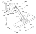
- FIGS. 7 and 8 are a front view and a side view showing an example of the configuration of the second passive arm 200, respectively.
- the elements arranged inside the members are also displayed by solid lines.
- the second passive arm 200 includes an arm body 210 and an end effector 220 connected to the tip of the arm body 210.
- the arm body 210 can operate with two or more degrees of freedom, and in the present embodiment, it can operate with three degrees of freedom.
- the end effector 220 has a configuration capable of applying an action to an object.
- the end effector 220 is an example of an engaging portion.
- the arm body 210 includes four links 211a to 211d, three passive movable portions 212a to 212c, and a load body 213.
- the link 211a is an example of the base of the arm main body 210, and is fixed to the support base 421 of the moving device 420.
- the link 211a has a rectangular plate-like shape in which the longitudinal direction is the direction D5A.
- the number of links may be 3 or less, 5 or more, and the number of passive movable parts may be 2 or less, or 4 or more. May be good.
- the passive movable portion 212a connects the link 211a and the link 211b so that they can move forward and backward relative to each other.
- the passive movable portion 212a is an example of an advancing / retreating movable portion.
- the link 211b has a rectangular plate shape and is arranged so as to face the link 211a.
- the passively movable portion 212a includes two guide portions 212aa and two or more engaging portions 212ab. Each guide portion 212aa is arranged on the surface of the link 211a. Each guide portion 212aa protrudes from the surface of the link 211a and extends in a band shape in the direction D5A. The two guide portions 212aa extend parallel to each other. The two guide portions 212aa form a track for guiding the movement of the link 211b, and may be a rail.
- Two or more engaging portions 212ab are arranged on the link 211b and slidably engage with the guide portion 212aa.
- the engaging portion 212ab can slide and move along the guide portion 212aa while maintaining the engagement so as not to deviate from the guide portion 212aa.
- four engaging portions 212ab are arranged, two engaging portions 212ab engage with one guide portion 212aa, and the other two engaging portions 212ab are different guide portions.
- the link 211b can move in the directions D5A and D5B along the guide portion 212aa.
- Direction D5B is the opposite direction of direction D5A.
- the passive movable portion 212b connects the link 211b and the base end portion of the link 211c so as to be relatively rotatable.
- the link 211b connects the passively movable portion 212a and the passively movable portion 212b.
- the passively movable portion 212b includes a rotating shaft 212ba integrally connected to the link 211b and a bearing 212bb fixed to the base end portion of the link 211c and rotatably supporting the rotating shaft 212ba.
- the link 211c is rotatable about the axis S21 of the rotation shaft 212ba. In this embodiment, the link 211c extends in a direction perpendicular to the axis S21, without limitation.
- the axial center S21 extends in a direction perpendicular to the directions D5A and D5B.
- the axis S21 extends in a direction intersecting the links 211a and 211b, for example, in a vertical direction.
- the passive movable portion 212b can function as a rotary joint.
- the passive movable portion 212b is an example of a rotatable movable portion.
- the passive movable portion 212c connects the tip end portion of the link 211c and the base end portion of the link 211d so as to be relatively rotatable.
- the link 211c connects the passive movable portion 212b and the passive movable portion 212c.
- the passive movable portion 212c includes a rotating shaft 212ca integrally connected to the base end portion of the link 211d, and a bearing 212cc fixed to the tip end portion of the link 211c and rotatably supporting the rotating shaft 212ca.
- the link 211d can rotate about the axis S22 of the rotation shaft 212ca.
- the link 211c has a parallel link configuration.
- the link 211c includes a first member 211ca, a second member 211cc and a third member 211cc.
- the first member 211ca, the second member 211cc, and the third member 211cc are columnar members.
- the first member 211ca connects the passive movable portions 212b and 212c. Specifically, one end of the first member 211ca is rotatably connected to the link 211b by the passive movable portion 212b, and the other end of the first member 211ca is rotated with the base end portion of the link 211d by the passive movable portion 212c. Connected movably.
- the second member 211cc extends along the first member 211ca and is rotatably connected to the link 211b at one end. Specifically, one end of the second member 211cb is connected to the link 211b at a position away from the first member 211ca. The other end of the second member 211cc is rotatably connected to one end of the third member 211cc. The third member 211cc is rotatably connected to the other end of the second member 211cc at one end and is connected to the passive movable portion 212c at the other end.
- the distance between the two connecting portions in the first member 211ca is equivalent to the distance between the two connecting portions in the second member 211cc.
- the distance between the connection portion between the link 211b and the first member 211ca and the connection portion between the link 211b and the second member 211cc is equivalent to the distance between the two connection portions in the third member 211cc. Therefore, when the first member 211ca rotates, the third member 211cc moves in parallel.
- the second portion 211db extends perpendicular to the first portion 211da, and the direction D7A is perpendicular to the direction D6A and away from the links 211a and 211b.
- the tip of the link 211d is connected to the end effector 220.
- the protrusion 222 can be engaged with the opening of the holder Va attached to the front hood VF and the rear gate VG of the vehicle body VB, and specifically, can be inserted into the opening.
- the holder Va is shown in FIG.
- the holder Va is a metal fitting held when the front hood VF and the rear gate VG are opened and closed.
- the arm connecting portion 230 is integrally arranged at the tip end portion of the link 211d.
- the arm connecting portion 230 has an engaging hole 231 that opens in the direction D6A.
- the engaging hole 231 is a hole into which the robot connecting body 322B of the second painting robot 300B can be inserted.
- the arm connecting portion 230 is an example of an engaging portion.
- the second passive arm 200 is arranged so that the directions D5A and D5B are along the directions D1A and D1B, the directions D6A are along the directions D2A, and the directions D7A and D7B are along the directions D3B and D3A, respectively.
- the second passive arm 200 can move the end effector 220 by three degrees of freedom, two degrees of freedom of rotation in the vertical direction and one degree of freedom of forward / backward movement in the horizontal direction.
- the robot arm 310B of the painting robot 300B can insert the robot connecting body 322B into the engaging hole 231 from the side.
- the second passive arm 200 includes locking devices 251 and 252 capable of locking the operations of the passive movable portions 212a and 212b, respectively.
- the locking devices 251 and 252 are locked using frictional force, but not limited to this.
- the locking device 251 locks the advancing / retreating operation of the passive movable portion 212a.
- the locking device 252 has the same configuration as the locking devices 151 and 152 of the first passive arm 100, and locks the rotational operation of the passive movable portion 212b.
- FIG. 9 is a block diagram showing an example of the configuration of the control devices 500A to 500C and their surroundings according to the embodiment.
- the third control device 500C is wired communication and wireless so that signals can be transmitted to and received from the first control device 500A, the second control device 500B, the line control device CPL of the painting line device PL, and the input / output device 700. They are connected to each other via communication or a combination thereof. Any wired or wireless communication may be used.
- the third control device 500C receives commands, information, data, etc. input to the input / output device 700 from the input / output device 700, and controls according to the commands, information, data, and the like.
- the third control device 500C outputs various information and data of the robot system 1 to the input / output device 700.
- the third control device 500C receives information indicating the operation status of each of the components to be controlled from the first control device 500A, the second control device 500B, and the line control device CPL, and is based on the information.
- the operation timing command of each control target component may be controlled to be transmitted to the first control device 500A, the second control device 500B, and the line control device CPL.
- the operation timing is the timing at which the operation is executed.
- the third control device 500C may be connected to the air supply device 600 and configured to control the operation of the air supply device 600.
- the information indicating the operation state of the painting line device PL from the line control device CPL is an example of the information of the object.
- the third control device 500C may include a computer device, and is configured to transmit and receive a signal to another control device or the like by I / O communication or the like and control the operation of the other control device or the like based on the signal. May be good.
- the third control device 500C is connected to one first control device 500A and one second control device 500B, but the first control device 500A controlled by the third control device 500C.
- the quantity of each of the second control device 500B and the second control device 500B may be any quantity.
- the second control device 500B controls the operations of the second painting robot 300B, the second passive arm 200, the moving devices 420 and 440, and the like in accordance with an operation timing command or the like received from the third control device 500C.
- the second control device 500B may be configured to control the operation of the servomotors of the arm drive devices MB1 to MB6, the on-off valves 601B to 603B, the sensors 241 and 242, and the servomotors of the mobile devices 420 and 440. good.
- the second control device 500B controls the operation of each controlled object by automatic operation according to the control program.
- the second control device 500B includes a computer device, and may further include a drive circuit for an electrical component such as a servomotor.
- the control devices 500A and 500B may be configured to servo control each servomotor.
- the control devices 500A and 500B acquire the detection result of the rotation sensor provided in the servomotor from each servomotor, acquire the supply current value from the drive circuit of the servomotor to the servomotor, and detect the rotation sensor.
- the result and the supply current value may be used as feedback information to determine the command value of the current to the servomotor.
- the supply current value may be a command value of the current supplied from the drive circuit to the servomotor, or may be a detection result of a current sensor that can be provided in the servomotor.
- the line control device CPL controls the operation of the painting line device PL.
- the line control device CPL may include a control panel such as a line controller.
- the line controller is also referred to as a "process control panel” or a "line control panel”.
- the input / output device 700 receives input of commands, information, data, etc. by a user such as an operator, and outputs the input to the third control device 500C or the like.
- the input / output device 700 receives information and data sent from the third control device 500C and the like, and presents the information and data to the user.
- the input / output device 700 includes an input device and a presentation device such as a display.
- the input device may be any known input device, and the presentation device may be any known device that provides perceptible information to the user through visual, auditory, and the like.
- control devices 500A to 500C may be electronic circuit boards, electronic control units, microcomputers, personal computers, workstations, smart devices such as smartphones and tablets, and other electronic devices.
- the controllers 500A to 500C may include a circuit, which circuit may include a processor and memory.
- the circuit may include a processing circuit.
- the circuit includes a CPU (Central Processing Unit) and the like as a processor, and a non-volatile semiconductor memory such as ROM (Read Only Memory) and a volatile semiconductor memory such as RAM (Random Access Memory) as memory. But it may be.
- ROM Read Only Memory
- RAM Random Access Memory
- a program for operating a CPU is stored in a ROM or the like in advance. The CPU reads the program from the ROM into the RAM and expands it.
- control devices 500A to 500C may be realized by a computer system including a processor, a memory, or the like, or may be realized by a dedicated hardware circuit such as an electronic circuit or an integrated circuit, and the computer may be realized. It may be realized by a combination of a system and a hardware circuit.
- the control devices 500A to 500C may be configured to execute each process by centralized control by a single device, or may be configured to execute each process by distributed control by cooperation of a plurality of devices. ..
- FIG. 10 is a block diagram showing an example of the functional configuration of the first control device 500A and the second control device 500B according to the embodiment.
- the first control device 500A and the second control device 500B have similar functional configurations.
- the first control device 500A includes an information processing unit 501A, a first signal processing unit 502A, a second signal processing unit 503A, a first movement control unit 504A, a second movement control unit 505A, and an arm control unit 506A.
- a coated valve control unit 507A, a locking valve control unit 508A, and a storage unit 509A are included as functional components.
- the function of the storage unit 509A may be realized by a memory or the like.
- the functions of the functional components other than the storage unit 509A may be realized by a processor or the like. Not all of the above functional components are required.
- the storage unit 509A stores various information and data, and makes it possible to read the stored information and data.
- the storage unit 509A stores a control program, various data, and the like.
- the first signal processing unit 502A receives a signal from the first sensor 141 and processes the signal. Based on the signal of the first sensor 141, the first signal processing unit 502A determines whether or not the robot coupling body 322A of the first painting robot 300A is inserted into the engaging hole 131 of the arm connecting portion 130 of the first passive arm 100. Is detected, and the detection result is output to the arm control unit 506A or the like.
- the second signal processing unit 503A receives a signal from the second sensor 142 and processes the signal.
- the second signal processing unit 503A detects whether or not an object exists in the protruding direction D4B from the protruding portion 122 of the end effector 120 of the first passive arm 100 based on the signal of the second sensor 142, and detects the detection result. Output to the arm control unit 506A or the like. For example, when the protrusion 122 is located directly above the gap VDa of the door VD of the vehicle body VB and faces the gap VDa, the second sensor 142 does not detect the object, so that the second signal processing unit 503A does not detect the object. The presence can be detected, thereby detecting the presence of the gap VDa.
- the second sensor 142 detects the inner surface of the outer plate of the door VD, so that the second signal processing unit 503A detects the presence of an object, thereby detecting the presence of an object. It is possible to detect the completion of insertion of the protrusion 122 into the gap VDa.
- the first movement control unit 504A controls the operation of the movement device 410 according to a command such as an operation timing from the third control device 500C and a control program. For example, the first movement control unit 504A calculates a target value such as the position and speed of the support base 411 of the movement device 410, and outputs a command value for moving the support base 411 according to the target value to the movement drive device 412. do.
- the command value may be a command value of the current supplied to the servo motor.
- the first movement control unit 504A may move the support base 411 to the movement drive device 412 so as to synchronize with the movement of the vehicle body VB by the painting line device PL.
- the second movement control unit 505A controls the operation of the movement device 430 according to a command such as an operation timing from the third control device 500C and a control program. For example, the second movement control unit 505A calculates a target value such as the position and speed of the support base 431 of the movement device 430, and outputs a command value for moving the support base 431 according to the target value to the movement drive device 432. do.
- the command value may be a command value of the current supplied to the servo motor.
- the second movement control unit 505A may move the support base 431 to the movement drive device 432 so as to synchronize with the movement of the vehicle body VB by the painting line device PL.
- the arm control unit 506A controls the operation of the robot arm 310A according to a command such as an operation timing from the third control device 500C and a control program. For example, the arm control unit 506A calculates a target value such as a position, a posture, a moving speed of the position, and a moving speed of the posture of the end effector 320A, and drives the command value for moving the end effector 320A according to the target value. Output from the device MA1 to MA6.
- the command value may be a command value of the current supplied to the servo motor.
- the arm control unit 506A controls the operation of the robot arm 310A for positioning the end effector 320A by using the detection results received from the signal processing units 502A and 503A.
- the paint valve control unit 507A controls the operation of the on-off valve 601A according to the control program. That is, the paint valve control unit 507A controls the injection of paint from the paint gun 321A of the end effector 320A.
- the locking valve control unit 508A controls the operation of the on-off valves 602A to 604A of the locking devices 151 to 153 of the first passive arm 100 according to the control program. That is, the locking valve control unit 508A controls the locking operation of the locking devices 151 to 153.
- the locking valve control unit 508A may use the detection results received from the signal processing units 502A and 503A for control.
- the second control device 500B includes an information processing unit 501B, a first signal processing unit 502B, a second signal processing unit 503B, a first movement control unit 504B, and a second movement control.
- a unit 505B, an arm control unit 506B, a coating valve control unit 507B, a locking valve control unit 508B, and a storage unit 509B are included as functional components.
- the function of the storage unit 509B may be realized by a memory or the like.
- the functions of the functional components other than the storage unit 509B may be realized by a processor or the like.
- each functional component of the second control device 500B is mainly different from the first control device 500A. The description of similarities will be omitted. Not all of the above functional components of the second controller 500B are essential.
- the first signal processing unit 502B processes the signal received from the first sensor 241 and outputs the processing result to the arm control unit 506B or the like. Based on the signal, the first signal processing unit 502B detects whether or not the robot coupling body 322B of the second painting robot 300B is inserted into the engaging hole 231 of the arm connecting portion 230 of the second passive arm 200. ..
- the second signal processing unit 503B processes the signal received from the second sensor 242 and outputs the processing result to the arm control unit 506B or the like.
- the protruding portion 222 of the end effector 220 of the second passive arm 200 is located directly below the opening of the holder Va of the front hood VF or the rear gate VG of the vehicle body VB. It can be detected that it is suitable for the opening.
- the first movement control unit 504B controls the operation of the movement device 420 according to the command and the control program from the third control device 500C.
- the second movement control unit 505B controls the operation of the movement device 440 according to the command and the control program from the third control device 500C.
- the arm control unit 506B controls the operation of the robot arm 310B according to a command and a control program from the third control device 500C. Further, the arm control unit 506B controls the operation of the robot arm 310B for positioning the end effector 320B by using the detection results received from the signal processing units 502B and 503B.
- step S102 the first control device 500A is operated by the robot arm 310A of the first painting robot 300A, the robot connecting body 322A is inserted into the engaging hole 131, and the robot connecting body 322A is connected to the arm connecting portion 130. Let me. That is, the first control device 500A connects the robot arm 310A and the first passive arm 100.
- step S103 the first control device 500A detects the completion of insertion of the robot coupling body 322A into the engaging hole 131, that is, the completion of coupling, based on the signal of the first sensor 141.
- step S107 When the first control device 500A detects the gap VDa based on the signal of the second sensor 142 (Yes in step S107), the first control device 500A proceeds to step S108, and if not detected (No in step S107), repeats step S106.
- the detection of the gap VDa means that the gap VDa is detected in the downward protruding direction of the protruding portion 122 of the end effector 120.
- step S108 the first control device 500A moves the end effector 120 downward D3B to the robot arm 310A while sensing the second sensor 142, and inserts the protrusion 122 into the gap VDa.
- step S111 when the door VD of the vehicle body VB is opened to a predetermined position, the first control device 500A operates the on-off valves 602A to 604A from the open state to the closed state, and all of the locking devices 151 to 153. Locking operation. As a result, the first passive arm 100 keeps the door VD in the open state.
- step S112 the first control device 500A is operated by the robot arm 310A to pull out the robot connecting body 322A from the engaging hole 131, and disconnect the robot connecting body 322A and the engaging hole 131.
- step S113 the first control device 500A completes the withdrawal of the robot connecting body 322A from the engaging hole 131 based on the signal of the first sensor 141, that is, the connection between the robot connecting body 322A and the engaging hole 131. Detects the completion of cancellation.
- FIG. 12 is a flowchart showing an example of the closing operation of the robot system 1 according to the embodiment.
- step S204 the first control device 500A operates the on-off valves 602A to 604A from the closed state to the open state, and causes all the locking devices 151 to 153 to be unlocked.
- step S205 the first control device 500A moves the end effector 120 horizontally to the robot arm 310A and closes the door VD of the vehicle body VB.
- step S207 the first control device 500A operates the on-off valves 602A to 604A from the open state to the closed state after the transition of the first passive arm 100 to the initial state is completed, and all of the locking devices 151 to 153. Locking operation. As a result, the first passive arm 100 maintains the initial state.
- step S209 the first control device 500A completes the withdrawal of the robot connecting body 322A from the engaging hole 131 based on the signal of the first sensor 141, that is, the connection between the robot connecting body 322A and the engaging hole 131. Detects the completion of cancellation.
- step S210 the first control device 500A causes the on-off valve 601A to operate from the closed state to the open state, and causes the robot arm 310A to perform the painting operation of other parts.
- the second control device 500B closes the front hood VF and the rear gate VG of the vehicle body VB by using the second painting robot 300B and the second passive arm 200 by performing the same processing as the above processing of the first control device 500A. can do.
- the objects to be operated by using the painting robots 300A and 300B which are active robots and the passive arms 100 and 200 are the door VD which can open and close the vehicle body VB, the front hood VF, and the target.
- the rear gate VG the target to be operated by the robot system 1 is not limited to these.
- the robot system 1 may be used for any object that is movable or movable.
- the robot system 1 may be used for an object that passively moves or moves by applying an external force.
- the robot system 1 moves or moves an object by using an active robot and a passive arm 100 or 200, and causes the active robot to move or move the object while the passive arm 100 or 200 maintains the object in a post-movement or post-movement state. It can be used in various cases such as performing work on an object.
- the control device can make the passive arm hold the posture by locking each passive movable portion to each locking device.
- the control device may cause each locking device to release the locking operation when the passive arm performs the operation of the object, and may cause each locking device to perform the locking operation after the operation.
- the passive arm can hold the object in the post-movement state, and the control device can cause the robot arm to perform the first movement with respect to the held object.
- the control device may cause the passive arm to perform an operation such as returning to the original state, and then cause each locking device to perform a locking operation. This prevents contact between the passive arm and the object or the robot arm due to the passive arm operating unintentionally.
- the object may include an opening / closing body capable of opening / closing operation, and the engaging portion may be engaged with the opening / closing body.
- the control device can cause the passive arm to open / close the opening / closing body by using the robot arm.
- the robot system includes a first passive arm that is a passive arm that opens and closes a first opening / closing body as an opening / closing body, and a passive arm that opens / closes a second opening / closing body as the opening / closing body.
- a second passive arm, a first arm moving device for moving the position of the first passive arm, and a second arm moving device for moving the position of the second passive arm are further provided, and the first opening / closing body is ,
- the second opening / closing body can be opened / closed in the vertical direction, and the control device is located at a position corresponding to the object based on the information of the object.
- the operation of the first arm moving device and the second arm moving device may be controlled so as to move the passive arm and the second passive arm.
- the arm connecting portion of the passive arm connected to the robot arm is connected to the robot connecting portion of the robot arm connected to the passive arm, and the passive arm is connected to the robot connecting portion. Relative rotation between the arm and the robot arm may be allowed.
- the configuration for causing the passive arm to follow the movement of the robot arm is simplified. ..
- the robot connecting portion and the arm connecting portion may be configured to be rotatable with respect to each other, the robot connecting portion itself may be configured to be rotatable, and the arm connecting portion itself may be rotatable. It may be configured to be.
- the passive arm has two or more passive movable parts that form the two or more degrees of freedom and operate by applying an external force to the passive arm, and the above-mentioned passive arm. It comprises three or more links connected to each other via two or more passive moving parts and an end effector located at the tip of the passive arm and configured to act on the object.
- the arm connecting portion of the passive arm connected to the robot arm may be arranged in the end effector.
- the end effector can be moved in the protruding direction of the protruding portion, and the protrusion can be engaged with the recess or opening of the object by the movement. Further, since the protruding portion is arranged at the tip of the extending portion, it is possible to reduce the contact between the end effector and the object. Therefore, it becomes easy to control the operation of the robot arm for engaging the end effector with the recess of the object.
- the passive arm can move the entire second to fourth links in the advancing / retreating direction of the advancing / retreating movable portion with respect to the first link.
- the passive arm can rotate the third link and the fourth link in the direction perpendicular to the rotation axis direction of the first rotatable portion and the second rotatable portion. Therefore, the passive arm can make a wide range of movement including the forward / backward movement of the second link and the turning movement of the third link and the fourth link into the fourth link.
- the robot arm is connected to the passive arm at or near the end effector.
- the end effector moves following the movement of the robot arm. Therefore, it becomes easy to control the movement of the robot arm for moving the end effector to the target position, the target posture, or a combination thereof.
- the end effector can engage the protrusion with the recess or opening of the object by being moved in the protruding direction of the protrusion. Since the protruding portion is arranged at the tip of the extending portion, it is possible to reduce the contact between the end effector and the object. Therefore, it becomes easy to control the operation of the robot arm for engaging the end effector with the recess or opening of the object.
- the control method is a control method of a robot system including a robot arm and a passive arm, which is operated by the robot arm that can be driven by itself and brings the robot arm close to the passive arm. That is, the robot arm is operated based on the detection signal of the first sensor which is arranged on either or both of the robot arm and the passive arm and detects the connection between the robot arm and the passive arm, and causes the robot arm to operate. To connect the passive arm and the passive arm, and to cause two or more locking devices arranged in two or more movable parts of the passive arm having two or more degrees of freedom to perform an unlocking operation.
- An object for which the passive arm is operated by a robot arm and the engaging portion of the passive arm is engaged based on a detection signal of a second sensor that detects an object placed on the passive arm and existing in a predetermined direction. Detecting the engagement target portion, operating the passive arm on the robot arm to engage the engagement portion with the engagement target portion, and engaging the robot arm with the engagement target portion.
- the passive arm is operated and the object is operated, the movable portion of the passive arm is locked by the locking device, and the robot arm is operated based on the detection signal of the first sensor. It includes operating and disconnecting the robot arm and the passive arm.
- the control method may be realized by a circuit such as a CPU or LSI, an IC card, a single module, or the like.
- the technique of the present disclosure may be a program for executing the control method, or may be a non-temporary computer-readable recording medium in which the program is recorded. Needless to say, the above program can be distributed via a transmission medium such as the Internet.
- the numbers such as ordinal numbers and quantities used above are all exemplified for the purpose of concretely explaining the technique of the present disclosure, and the present disclosure is not limited to the exemplified numbers.
- the connection relationships between the components are exemplified for the purpose of specifically explaining the technique of the present disclosure, and the connection relationships that realize the functions of the present disclosure are not limited thereto.
- the division of blocks in the functional block diagram is an example, and multiple blocks are realized as one block, one block is divided into multiple blocks, some functions are transferred to other blocks, or two or more of these are combined. It may be combined. A single piece of hardware or software may process the functions of multiple blocks with similar functions in parallel or in a time division manner.
Landscapes
- Engineering & Computer Science (AREA)
- Robotics (AREA)
- Mechanical Engineering (AREA)
- Manipulator (AREA)
Priority Applications (3)
| Application Number | Priority Date | Filing Date | Title |
|---|---|---|---|
| JP2022571407A JP7512432B2 (ja) | 2020-12-21 | 2021-12-17 | ロボットシステム及び受動アーム |
| CN202180085806.3A CN116635191A (zh) | 2020-12-21 | 2021-12-17 | 机器人系统、控制方法及被动臂 |
| US18/268,334 US20240066696A1 (en) | 2020-12-21 | 2021-12-17 | Robot system, control method, and passive arm |
Applications Claiming Priority (4)
| Application Number | Priority Date | Filing Date | Title |
|---|---|---|---|
| JP2020-211593 | 2020-12-21 | ||
| JP2020211593 | 2020-12-21 | ||
| JP2020211594 | 2020-12-21 | ||
| JP2020-211594 | 2020-12-21 |
Publications (1)
| Publication Number | Publication Date |
|---|---|
| WO2022138502A1 true WO2022138502A1 (ja) | 2022-06-30 |
Family
ID=82157798
Family Applications (1)
| Application Number | Title | Priority Date | Filing Date |
|---|---|---|---|
| PCT/JP2021/046801 Ceased WO2022138502A1 (ja) | 2020-12-21 | 2021-12-17 | ロボットシステム、制御方法及び受動アーム |
Country Status (3)
| Country | Link |
|---|---|
| US (1) | US20240066696A1 (https=) |
| JP (1) | JP7512432B2 (https=) |
| WO (1) | WO2022138502A1 (https=) |
Families Citing this family (2)
| Publication number | Priority date | Publication date | Assignee | Title |
|---|---|---|---|---|
| JP7764277B2 (ja) * | 2022-02-28 | 2025-11-05 | 株式会社安川電機 | ドア開閉ロボット、及び、ドア開閉システム |
| US12589501B2 (en) * | 2023-03-03 | 2026-03-31 | Kawasaki Jukogyo Kabushiki Kaisha | Door opening and closing robot and method of opening and closing door using the same |
Citations (11)
| Publication number | Priority date | Publication date | Assignee | Title |
|---|---|---|---|---|
| JPS60201845A (ja) * | 1984-03-26 | 1985-10-12 | Daikin Ind Ltd | ドリル等の回転工具を用いた加工装置 |
| JPS63267180A (ja) * | 1987-04-24 | 1988-11-04 | 三菱重工業株式会社 | ハンドリング方法及びその装置 |
| JPH0655484A (ja) * | 1992-08-05 | 1994-03-01 | Hitachi Ltd | ロボットを用いた組立装置 |
| JPH0866889A (ja) * | 1994-08-29 | 1996-03-12 | Toransapooto:Kk | 関節機構およびその機構を用いたユニバーサルアーム装置 |
| JPH091492A (ja) * | 1995-06-19 | 1997-01-07 | Yaskawa Electric Corp | 重量ワークを搬送する方法 |
| WO2008108401A1 (ja) * | 2007-03-08 | 2008-09-12 | Kabushiki Kaisha Yaskawa Denki | 塗装システム |
| WO2010091722A1 (en) * | 2009-02-11 | 2010-08-19 | Abb Research Ltd | Dual arm robot |
| WO2011055766A1 (ja) * | 2009-11-06 | 2011-05-12 | 本田技研工業株式会社 | 塗装システム |
| JP2013031890A (ja) * | 2011-08-01 | 2013-02-14 | Yaskawa Electric Corp | 塗装システムおよびドア開閉用ロボットの開閉ハンド |
| JP2018122367A (ja) * | 2017-01-30 | 2018-08-09 | 川崎重工業株式会社 | 搬送システム及びその運転方法 |
| JP2019048364A (ja) * | 2017-09-12 | 2019-03-28 | Ckd株式会社 | ワーク搬送装置 |
Family Cites Families (6)
| Publication number | Priority date | Publication date | Assignee | Title |
|---|---|---|---|---|
| DE2530261C2 (de) * | 1974-10-22 | 1986-10-23 | Asea S.p.A., Mailand/Milano | Programmiereinrichtung für einen Manipulator |
| US6757586B2 (en) * | 2001-09-05 | 2004-06-29 | Abb Automation Inc. | Multiple arm robot arrangement |
| US7153454B2 (en) * | 2003-01-21 | 2006-12-26 | University Of Southern California | Multi-nozzle assembly for extrusion of wall |
| US8239063B2 (en) * | 2008-07-29 | 2012-08-07 | Fanuc Robotics America, Inc. | Servo motor monitoring and hood/deck exchange to enhance the interior coating process |
| FR2995227B1 (fr) * | 2012-09-10 | 2014-10-03 | Sames Technologies | Installation de projection de produit de revetement |
| US20170356159A1 (en) * | 2016-06-11 | 2017-12-14 | Howard Bennett | Dirt scooping, moving, and dumping apparatus for attachment to a tractor |
-
2021
- 2021-12-17 JP JP2022571407A patent/JP7512432B2/ja active Active
- 2021-12-17 WO PCT/JP2021/046801 patent/WO2022138502A1/ja not_active Ceased
- 2021-12-17 US US18/268,334 patent/US20240066696A1/en not_active Abandoned
Patent Citations (11)
| Publication number | Priority date | Publication date | Assignee | Title |
|---|---|---|---|---|
| JPS60201845A (ja) * | 1984-03-26 | 1985-10-12 | Daikin Ind Ltd | ドリル等の回転工具を用いた加工装置 |
| JPS63267180A (ja) * | 1987-04-24 | 1988-11-04 | 三菱重工業株式会社 | ハンドリング方法及びその装置 |
| JPH0655484A (ja) * | 1992-08-05 | 1994-03-01 | Hitachi Ltd | ロボットを用いた組立装置 |
| JPH0866889A (ja) * | 1994-08-29 | 1996-03-12 | Toransapooto:Kk | 関節機構およびその機構を用いたユニバーサルアーム装置 |
| JPH091492A (ja) * | 1995-06-19 | 1997-01-07 | Yaskawa Electric Corp | 重量ワークを搬送する方法 |
| WO2008108401A1 (ja) * | 2007-03-08 | 2008-09-12 | Kabushiki Kaisha Yaskawa Denki | 塗装システム |
| WO2010091722A1 (en) * | 2009-02-11 | 2010-08-19 | Abb Research Ltd | Dual arm robot |
| WO2011055766A1 (ja) * | 2009-11-06 | 2011-05-12 | 本田技研工業株式会社 | 塗装システム |
| JP2013031890A (ja) * | 2011-08-01 | 2013-02-14 | Yaskawa Electric Corp | 塗装システムおよびドア開閉用ロボットの開閉ハンド |
| JP2018122367A (ja) * | 2017-01-30 | 2018-08-09 | 川崎重工業株式会社 | 搬送システム及びその運転方法 |
| JP2019048364A (ja) * | 2017-09-12 | 2019-03-28 | Ckd株式会社 | ワーク搬送装置 |
Also Published As
| Publication number | Publication date |
|---|---|
| JPWO2022138502A1 (https=) | 2022-06-30 |
| JP7512432B2 (ja) | 2024-07-08 |
| US20240066696A1 (en) | 2024-02-29 |
Similar Documents
| Publication | Publication Date | Title |
|---|---|---|
| Marvel et al. | Multi-robot assembly strategies and metrics | |
| JP7512432B2 (ja) | ロボットシステム及び受動アーム | |
| US7181314B2 (en) | Industrial robot with controlled flexibility and simulated force for automated assembly | |
| Pandilov et al. | COMPARISON OF THE CHARACTERISTICS BETWEEN SERIAL AND PARALLEL ROBOTS. | |
| CN102239454B (zh) | 用于在机械手的控制装置中输入指令的方法和设备 | |
| Kazemi et al. | Human-inspired force compliant grasping primitives | |
| JPWO2003086718A1 (ja) | ロボット | |
| Kim et al. | Remotely manipulated peg-in-hole task conducted by cable-driven parallel robots | |
| Marvel et al. | Best practices and performance metrics using force control for robotic assembly | |
| CN116635191A (zh) | 机器人系统、控制方法及被动臂 | |
| Morris et al. | Force guided assemblies using a novel parallel manipulator | |
| US12441002B2 (en) | Robotic gripper with seal detection | |
| Wu et al. | Collaboration of multiple mobile manipulators with compliance based leader/follower approach | |
| KR102923973B1 (ko) | 높은 이펙터 감도를 제공하고 로봇 바디부와 상호작용이 가능한 혼합력 제어법을 갖는 공동-핸들링 로봇 | |
| Budin et al. | Modelling and proportional-integral-derivative controller design for position analysis of the 3-degree of freedom | |
| Bergerman et al. | Control of cooperative underactuated manipulators: a robustness comparison study | |
| JP7278198B2 (ja) | ロボットシステム及びその運転方法 | |
| Kuo et al. | Experimental and Numerical Study on the Semi‐Closed Loop Control of a Planar Parallel Robot Manipulator | |
| Hung et al. | An Intelligent control method for redundant robotic manipulators with output constraints | |
| Sung et al. | Robot Manipulator Based on a Wire-driven Variable Link Mechanism to Control Workspace | |
| Deroo et al. | The need for task-specific execution in robot manipulation: Skill design for energy-efficient control | |
| Best et al. | Model predictive control for pneumatically actuated soft robots | |
| CN113910242A (zh) | 一种机械手运动路径模拟方法 | |
| Prasad et al. | Motion control of a pair of cylindrical manipulators in a constrained 3-dimensional workspace | |
| TWI914728B (zh) | 具有關節彎折或可變長度上臂之機器人系統及用以控制其之方法與電腦程式產品 |
Legal Events
| Date | Code | Title | Description |
|---|---|---|---|
| 121 | Ep: the epo has been informed by wipo that ep was designated in this application |
Ref document number: 21910647 Country of ref document: EP Kind code of ref document: A1 |
|
| ENP | Entry into the national phase |
Ref document number: 2022571407 Country of ref document: JP Kind code of ref document: A |
|
| WWE | Wipo information: entry into national phase |
Ref document number: 202180085806.3 Country of ref document: CN |
|
| WWE | Wipo information: entry into national phase |
Ref document number: 18268334 Country of ref document: US |
|
| NENP | Non-entry into the national phase |
Ref country code: DE |
|
| 122 | Ep: pct application non-entry in european phase |
Ref document number: 21910647 Country of ref document: EP Kind code of ref document: A1 |