WO2022137695A1 - 自動分析装置、位置調整用治具及び位置調整方法 - Google Patents
自動分析装置、位置調整用治具及び位置調整方法 Download PDFInfo
- Publication number
- WO2022137695A1 WO2022137695A1 PCT/JP2021/035667 JP2021035667W WO2022137695A1 WO 2022137695 A1 WO2022137695 A1 WO 2022137695A1 JP 2021035667 W JP2021035667 W JP 2021035667W WO 2022137695 A1 WO2022137695 A1 WO 2022137695A1
- Authority
- WO
- WIPO (PCT)
- Prior art keywords
- nozzle
- adjusting jig
- position adjusting
- height
- jig
- Prior art date
- Legal status (The legal status is an assumption and is not a legal conclusion. Google has not performed a legal analysis and makes no representation as to the accuracy of the status listed.)
- Ceased
Links
Images


Classifications
-
- G—PHYSICS
- G01—MEASURING; TESTING
- G01N—INVESTIGATING OR ANALYSING MATERIALS BY DETERMINING THEIR CHEMICAL OR PHYSICAL PROPERTIES
- G01N35/00—Automatic analysis not limited to methods or materials provided for in any single one of groups G01N1/00 - G01N33/00; Handling materials therefor
- G01N35/10—Devices for transferring samples or any liquids to, in, or from, the analysis apparatus, e.g. suction devices, injection devices
- G01N35/1081—Devices for transferring samples or any liquids to, in, or from, the analysis apparatus, e.g. suction devices, injection devices characterised by the means for relatively moving the transfer device and the containers in an horizontal plane
- G01N35/109—Devices for transferring samples or any liquids to, in, or from, the analysis apparatus, e.g. suction devices, injection devices characterised by the means for relatively moving the transfer device and the containers in an horizontal plane with two horizontal degrees of freedom
-
- G—PHYSICS
- G01—MEASURING; TESTING
- G01N—INVESTIGATING OR ANALYSING MATERIALS BY DETERMINING THEIR CHEMICAL OR PHYSICAL PROPERTIES
- G01N35/00—Automatic analysis not limited to methods or materials provided for in any single one of groups G01N1/00 - G01N33/00; Handling materials therefor
- G01N35/10—Devices for transferring samples or any liquids to, in, or from, the analysis apparatus, e.g. suction devices, injection devices
- G01N35/1009—Characterised by arrangements for controlling the aspiration or dispense of liquids
- G01N35/1011—Control of the position or alignment of the transfer device
-
- G—PHYSICS
- G01—MEASURING; TESTING
- G01N—INVESTIGATING OR ANALYSING MATERIALS BY DETERMINING THEIR CHEMICAL OR PHYSICAL PROPERTIES
- G01N35/00—Automatic analysis not limited to methods or materials provided for in any single one of groups G01N1/00 - G01N33/00; Handling materials therefor
- G01N35/02—Automatic analysis not limited to methods or materials provided for in any single one of groups G01N1/00 - G01N33/00; Handling materials therefor using a plurality of sample containers moved by a conveyor system past one or more treatment or analysis stations
- G01N35/04—Details of the conveyor system
- G01N2035/0439—Rotary sample carriers, i.e. carousels
-
- G—PHYSICS
- G01—MEASURING; TESTING
- G01N—INVESTIGATING OR ANALYSING MATERIALS BY DETERMINING THEIR CHEMICAL OR PHYSICAL PROPERTIES
- G01N35/00—Automatic analysis not limited to methods or materials provided for in any single one of groups G01N1/00 - G01N33/00; Handling materials therefor
- G01N35/02—Automatic analysis not limited to methods or materials provided for in any single one of groups G01N1/00 - G01N33/00; Handling materials therefor using a plurality of sample containers moved by a conveyor system past one or more treatment or analysis stations
- G01N35/04—Details of the conveyor system
- G01N2035/0474—Details of actuating means for conveyors or pipettes
- G01N2035/0491—Position sensing, encoding; closed-loop control
-
- G—PHYSICS
- G01—MEASURING; TESTING
- G01N—INVESTIGATING OR ANALYSING MATERIALS BY DETERMINING THEIR CHEMICAL OR PHYSICAL PROPERTIES
- G01N35/00—Automatic analysis not limited to methods or materials provided for in any single one of groups G01N1/00 - G01N33/00; Handling materials therefor
- G01N35/10—Devices for transferring samples or any liquids to, in, or from, the analysis apparatus, e.g. suction devices, injection devices
- G01N35/1081—Devices for transferring samples or any liquids to, in, or from, the analysis apparatus, e.g. suction devices, injection devices characterised by the means for relatively moving the transfer device and the containers in an horizontal plane
- G01N35/109—Devices for transferring samples or any liquids to, in, or from, the analysis apparatus, e.g. suction devices, injection devices characterised by the means for relatively moving the transfer device and the containers in an horizontal plane with two horizontal degrees of freedom
- G01N2035/1093—Cylindrical, e.g. variable radius and angle
Definitions
- This disclosure relates to an automatic analyzer, a position adjustment jig, and a position adjustment method.
- An automated analyzer used for chemical analysis such as biochemical analyzers and immunoanalyzers in clinical examinations has a dispensing mechanism equipped with a nozzle for dispensing samples and reagents. It is preferable that the nozzle is adjusted so as to stop at the center for each stop position.
- Patent Document 1 describes a technique for detecting an inclined surface of a jig by repeatedly moving the dispensing probe downward (paragraphs 0088 to 0105, FIG. 10).
- An object to be solved by the present disclosure is to provide an automatic analyzer, a position adjusting jig, and a position adjusting method capable of positioning in a short time.
- a nozzle that sucks fluid in a container housed in a housing portion arranged on a locus during rotation or discharges fluid to the container at least one is provided in a circumferential direction in a horizontal plane.
- a height positioning mechanism and an arithmetic control device for controlling the circumferential positioning mechanism are provided. Other solutions will be described later in the form for carrying out the invention.
- Top view of the automated analyzer The figure explaining the dispensing of a sample and a reagent by a nozzle. The figure explaining the alignment of the nozzle in the radial direction (the figure which shows before the alignment).
- Perspective view of the position adjustment jig The figure explaining the alignment of the nozzle in the radial direction (the figure which shows after the alignment).
- Top view of the position adjustment jig according to another embodiment.
- the side view of the position adjustment jig which concerns on another embodiment.
- Top view explaining when the alignment is correct and when it is incorrect (a diagram showing the state when contacted from one direction).
- Top view explaining when the alignment is correct and when it is incorrect (a diagram showing the state when contacted from another direction).
- FIG. 1 is a top view of the automated analyzer 100.
- a sample container 102 for holding a sample (sample) is erected on the transfer rack 101 of the automatic analyzer 100, and the sample container 102 is placed at a dispensing position near the nozzle 203 (FIG. 2) by the rack transfer line 117. Will be moved to.
- the nozzle 203 performs at least one of suction of the reaction liquid (an example of a fluid) in the reaction vessel 105 (an example of a container) and ejection of a sample and a reagent (an example of a fluid) into the reaction vessel 105. It is a thing.
- a plurality of reaction vessels 105 can be installed in the incubator (reaction disk) 104, and the incubator 104 can rotate in a horizontal plane because each of the reaction vessels 105 installed in the circumferential direction is moved to a predetermined position. ..
- the transport mechanism 106 can move in three directions of the X-axis, the Y-axis, and the Z-axis.
- the transport mechanism 106 moves within a range of the holding member 107, the stirring mechanism 108, the waste hole 109, the mounting position 110 of the tip 119 (FIG. 3A), and the predetermined position of the incubator 104, and transports the tip 119 and the reaction vessel 105.
- a plurality of unused reaction vessels 105 and chips 119 are installed on the holding member 107.
- the transport mechanism 106 moves above the holding member 107, descends to grip the unused reaction vessel 105, then rises, further moves above a predetermined position of the incubator 104, and descends to install the reaction vessel 105. do.
- the transport mechanism 106 moves above the holding member 107, descends to grip the unused tip 119, then rises, moves above the mounting position 110, and descends to install the tip 119.
- the nozzle 203 (FIG. 2) can rotate and move up and down in a horizontal plane, rotates above the mounting position 110, then descends, and press-fits the tip 119 into the tip of the nozzle 203 for mounting.
- the nozzle 203 equipped with the chip 119 moves above the sample container 102 placed on the transport rack 101 and then descends to suck a predetermined amount of the sample held in the sample container 102.
- the nozzle 203 that has sucked the sample moves above the incubator 104 and then descends to discharge the sample into the unused reaction vessel 105 held in the incubator 104.
- the nozzle 203 moves above the disposal hole 109 and discards the used tip 119 from the disposal hole 109.
- a plurality of reagent containers 118 are installed on the reagent disk 111.
- a cover 112 (partially deleted to visualize the inside in the illustrated example) is provided on the upper part of the reagent disk 111, and the inside of the reagent disk 111 is kept at a predetermined temperature.
- An opening 113 is provided in a part of the cover 112.
- the nozzle 114 can be rotated and moved up and down in a horizontal plane, rotates above the opening 113 and then descends, and the tip of the nozzle 114 is immersed in a reagent in a predetermined reagent container 118 to obtain a predetermined amount of reagent. Aspirate.
- the nozzle 114 then rises and then rotates above a predetermined position in the incubator 104 to eject the reagent into the reaction vessel 105.
- the reaction vessel 105 from which the sample and the reagent are discharged is moved to a predetermined position by the rotation of the incubator 104, and is transported to the stirring mechanism 108 by the transport mechanism 106.
- the stirring mechanism 108 stirs and mixes the sample and the reagent in the reaction vessel 105 by applying a rotary motion to the reaction vessel 105.
- the reaction vessel 105 after stirring is returned to a predetermined position of the incubator 104 by the transfer mechanism 106.
- the nozzle 115 can rotate and move up and down in a horizontal plane, dispense samples and reagents, finish stirring, move above the reaction vessel 105 after a predetermined reaction time in the incubator 104, and descend. , The reaction solution in the reaction vessel 105 is sucked. The reaction solution sucked by the nozzle 115 is analyzed by the detector unit 116. The reaction vessel 105 sucked by the reaction solution is moved to a predetermined position by the rotation of the incubator 104, moved from the incubator 104 to the upper part of the waste hole 109 by the transport mechanism 106, and is discarded in the waste hole 119.
- the nozzles 203, 114, and 115 independently suck and discharge the fluids of the sample, the reagent, and the reaction solution, and the alignment of the nozzle 203 is mainly described in the present specification.
- the automated analyzer 100 includes one nozzle (not shown) for suction and discharge of each fluid by cleaning with a cleaning liquid, and the alignment of the nozzles is the same as the alignment of the following nozzles 203. It is done in the same way.
- the alignment of the nozzles 114 and 115 is performed in the same manner as the alignment of the nozzle 203 below.
- the automatic analyzer 100 includes an arithmetic control device 800 that controls a rotation mechanism 400 (FIG. 3A), a height positioning mechanism 500 (FIG. 5), and a circumferential positioning mechanism 600 (FIG. 5).
- arithmetic and control devices 800 are shown, for example, a CPU (Central Processing Unit), It is equipped with RAM (Random Access Memory), ROM (Read Only Memory), etc.
- the arithmetic control device 800 is embodied when a predetermined control program stored in the ROM is expanded in the RAM and executed by the CPU.
- FIG. 2 is a diagram illustrating dispensing of a sample and a reagent by a nozzle 203.
- the nozzle 203 is a suction of a reaction solution (an example of a fluid) in a reaction vessel 105 housed in a storage unit 120 arranged on a circumference 204, which is a trajectory during rotation, or a sample and a reagent (fluid) to the reaction vessel 105. At least one of the discharges of (1)) is performed.
- the nozzle 203 is installed below the tip of the arm 202 attached to the rotating shaft 201.
- the storage unit 120 is an incubator 104 in which a reaction vessel 105 (an example of a container) capable of accommodating a sample and a reagent as a fluid is continuously arranged in the circumferential direction, or a sample, a reagent, or a nozzle as a fluid. It is provided in at least one of a transport rack 101 holding a container containing at least one of the cleaning liquids for cleaning 203, a reagent disk 111, and a cleaning liquid holder (not shown) (all of which are examples of holders). By doing so, it is possible to align each container such as the sample container 102, the reaction container 105, and the reagent container 118 housed in these storage units 120.
- the cleaning liquid is used when at least two of the sample, the reagent, or the cleaning liquid are sucked and discharged by one nozzle 203, and the nozzle 203 for sucking and discharging the sample, the reagent, or the cleaning liquid is provided respectively.
- the cleaning solution may not be used in the water. In the illustrated example, no cleaning solution is used.
- the nozzle 203 passes through the mounting position 110, the sample suction position 207 on the transport rack 101, the sample discharge position 209 on the incubator 104, and the disposal hole 109.
- FIG. 3A is a diagram for explaining the alignment of the nozzle 203 in the radial direction, and is a diagram showing the alignment before the alignment.
- the automatic analyzer 100 includes a rotation mechanism 400 for rotating the nozzle 203 in the circumferential direction in a horizontal plane, and the rotation mechanism 400 includes a rotation shaft 201, a motor (not shown) for rotating the rotation shaft 201 in the circumferential direction, an arm 202, and the arm 202. It is equipped with a detection mechanism 305 and the like.
- the rotation mechanism 400 is connected to the arithmetic control device 800 (FIG. 1) by an electric signal line (not shown).
- the nozzle 203 has a shape in which the outer diameter changes in the height direction, and includes, for example, a chip 119 having a shape of, for example, a cone that narrows downward.
- both the radial direction and the circumferential direction of the nozzle 203 are aligned.
- the nozzle 203 should be more centered with respect to the suction and discharge positions from the viewpoint of suppressing contact with the reaction vessel 105 and reducing dead volume as much as possible.
- the turning radius L of the nozzle 203 may deviate. Therefore, by performing radial alignment, the actual turning radius L1 can be brought closer to the design ideal turning radius L2 (FIG. 3C).
- the automatic analyzer 100 includes an adjusting mechanism 302 that adjusts at least one of the radial position of the nozzle 203 and the angle of the nozzle 203 with respect to the rotating shaft 201 that rotates the nozzle 203.
- the adjusting mechanism 302 adjusts both the radial position and the angle.
- the adjusting mechanism 302 is, for example, a feed screw, an actuator, or the like. Further, the adjusting mechanism 302 can be configured such that, for example, the screw hole for fastening is made into an oval hole so that the screw can be displaced inside the oval hole.
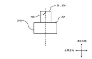
- FIG. 3B is a perspective view of the position adjusting jig 303.
- the position adjustment jig 303 is a reaction vessel 105 (FIG. 1, an example of a vessel) containing a fluid such as a reaction liquid that is sucked or discharged by a nozzle 203 (FIG. 3A) that can rotate in a horizontal plane in the automatic analyzer 100. ) Can be accommodated in the accommodating portion 120 (FIG. 3A).
- the position adjusting jig 303 projects upward of the accommodating portion 120 when accommodating in the accommodating portion 120 (FIG. 3A), and the protruding portion has a flange-like structure.
- the protruding portion is a circle having a radius R when viewed from above.
- the position adjusting jig 303 is provided with an adjusting mark 306 on the upper end surface 304 showing a partial arc of the circumference 204 (FIG. 2) which is a locus of the nozzle 203 when rotating.
- the user adjusts at least one of the radial position or the angle of the nozzle 203 so that the tip of the nozzle 203 is visually arranged above the adjusting mark 306. , The radial alignment can be easily performed.
- the adjustment mark 306 is a mark that serves as a guide for the nozzle rotation radius L (FIG. 3A), and the user operates the adjustment mechanism 302 (FIG. 3A) so as to match the adjustment mark 306, and the nozzle 203 rotation radius L.
- the adjustment mark 306 may have good visibility such as a scribe line, a groove, a color code indicating an adjustment allowable range, a hole indicating the center, and a point.
- the position adjusting jig 303 has irregularities (not shown) on the side walls, the bottom surface, and the like that suppress the rotation of the position adjusting jig 303. As a result, the adjustment mark 306, which is a guideline for adjustment, does not shift.
- the position adjusting jig 303 includes a core 311 exposed on the upper end surface 304, a surface layer portion 313, and an insulating layer 312.
- the surface layer portion 313 is arranged outside the core 311 and is exposed to the upper end surface 304, and is different in volume or dielectric constant from the core 311.
- the insulating layer 312 insulates the core 311 and the surface layer portion 313.
- the rotation mechanism 400 includes a detection mechanism 305 (FIG. 3A) that detects contact with the nozzle 203 due to a change in capacitance, and the contact between the nozzle 203 and the position adjusting jig 303 is electrostatic capacitance. Detected based on changes.
- the position adjusting jig 303 configured in this way, the contact with the center of the position adjusting jig 303 by the contact with the core 311 can be detected by the change in capacitance, and the contact with the surface layer portion 313 can be detected.
- the fact that the nozzle 203 is in contact from the side can also be detected by the change in capacitance.
- Which of the core 311 and the surface layer 313 is in contact can be determined based on, for example, whether or not the capacitance detected by the detection mechanism 305 exceeds the threshold value. The determination can be made, for example, by the arithmetic control device 800 (FIG. 1) connected to the detection mechanism 305 via an electric signal line (not shown).
- the core 311 is arranged at a position corresponding to the central portion (FIG. 3A, which may be near the center) of the reaction vessel 105 (FIG. 1, an example of the vessel).
- the center line 210 of the position adjusting jig 303 coincides with the center line of the reaction vessel 105 (not shown, the intersection of diagonal lines in the case of a rectangle), and when the position is accurately aligned as shown in the figure, the sample is discharged. Matches position 209.
- the nozzle 203 (FIG. 3A) is arranged at the center of the reaction vessel 105 when the reaction vessel 105 (FIG. 2) is accommodated in the accommodating portion 120 (FIG. 3A) by detecting the contact with the core 311. can.
- the shape of the position adjusting jig 303 is not limited to the illustrated example, and may be any shape as long as the distance from the contact point 405 (FIG. 6B) to the center line 210 of the position adjusting jig 303 can be calculated. ..
- FIG. 3C is a diagram for explaining the alignment of the nozzle 203 in the radial direction, and is a diagram showing the alignment after the alignment.
- the sample ejection position 209 by the nozzle 203 is the same position as the central portion of the reaction vessel 105. It coincides with the center line 210 of the adjusting jig 303.
- FIG. 4A is a top view of the position adjusting jig 3031 according to another embodiment.
- FIG. 4B is a side view of the position adjusting jig 3031 according to another embodiment.
- the adjusting mark 306 is a convex portion 3061 formed on the upper end surface 304 as shown in FIG. 4B, and the convex portion 3061 is formed as a part of an arc having a circumference 204. ..
- the radial width of the protrusion 3061 can be, for example, the same as the size (usually the diameter) of the core 311 (FIG. 3B).
- the user may operate the adjusting mechanism 302 (FIG. 3A) so that the nozzle 203 is arranged above the convex portion 3061.
- the nozzle 203 is arranged above the convex portion 3061.
- at least one of the volume and the dielectric constant is made of a material different from the convex portion 3061 on the side surface. You can do it.
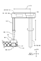
- FIG. 5 is a diagram showing a state in which the nozzle 203 is in contact with the upper end surface 304 of the position adjusting jig 303.
- the automatic analyzer 100 includes a height positioning mechanism 500 that positions the position adjusting jig 303 housed in the housing unit 120 in the height direction by driving the nozzle 203.
- the height positioning mechanism 500 includes a rotating shaft 201, an arm 202, a lowering mechanism (not shown) for lowering the nozzle 203, and a detection mechanism 305.
- the height positioning mechanism 500 is connected to the arithmetic control device 800 (FIG. 1) by an electric signal line (not shown).
- the height position to be determined is, for example, a deviation (difference) from the actual height position with respect to the height position of the upper end surface 304 of the position adjustment jig 303 in design.
- a deviation can be determined, for example, based on the design descent distance of the nozzle 203 and the actual descent distance, and may be referred to as a "height adjustment value" in the following.
- the height adjustment value is calculated and stored by, for example, the arithmetic control device 800 (FIG. 1). Further, at the time of sample analysis, the nozzle 203 moves in the height direction based on the amount obtained by adding or subtracting the height adjustment value with respect to the design value.
- the height positioning mechanism 500 determines the height position of the position adjusting jig 303 by detecting the contact position between the upper end surface 304 of the position adjusting jig 303 detected by the descent of the nozzle 203 and the nozzle 203. .. That is, after adjusting the position of the nozzle 203 in the radial direction, the height positioning mechanism 500 lowers the nozzle 203 by a lowering mechanism (not shown) and brings the nozzle 203 into contact with the position adjusting jig 303. Thereby, the height position of the position adjusting jig 303 can be determined.
- the nozzle 203 comes into contact with the core 311 (FIG. 3B) if it is accurately positioned in the radial direction. However, if the position adjustment is poor, the nozzle 203 may come into contact with the surface layer portion 313 or may not come into contact with the position adjustment jig 303. In this case, the radial alignment is performed again.
- the nozzle 203 is configured to be capable of sucking and discharging at least one of a sample as a fluid, a reagent, or a cleaning liquid of the nozzle 203. Therefore, the nozzle 203 is used to detect both the contact of the sample, the reagent or the cleaning liquid with at least one fluid and the contact with the position adjusting jig 303. At least the lower end of the nozzle 203 is made of resin, and specifically, the nozzle 203 includes, for example, a resin chip 119 (FIG. 3A).
- the arithmetic control device 800 (FIG. 1) makes the detection sensitivity of the position adjusting jig 303 by the detection mechanism 305 higher than the detection sensitivity of the fluid.
- the contact with the solid position adjusting jig 303 can be easily detected because the capacitance change due to the contact is large.
- the contact portion with the position adjusting jig 303 is made of resin, the contact area is small depending on the detection mechanism 305 adjusted to capture the change in capacitance caused by the contact with the fluid. It is difficult to detect contact with the solid position adjusting jig 303. Therefore, by increasing the detection sensitivity at the time of contact detection higher than the detection sensitivity at the time of fluid contact, it is possible to easily detect the contact with the position adjusting jig 303.
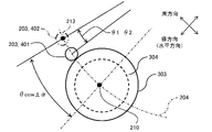
- FIG. 6A is a top view of the circumferential alignment from one direction (counterclockwise in the illustrated example).
- FIG. 6B is a side view at the time of peripheral alignment from one direction.
- the automatic analyzer 100 (FIG. 1) accommodates the position adjusting jig 303 by contacting the position adjusting jig 303 with the nozzle 203 from the side.
- a circumferential positioning mechanism 600 for positioning the accommodating portion 120 in the circumferential direction is provided.
- the circumferential positioning mechanism 600 includes a rotation shaft 201 (FIG. 5), an arm 202 (FIG. 5), a lowering mechanism (not shown), and a detection mechanism 305 (FIG. 5).
- the circumferential positioning mechanism 600 is connected to the arithmetic control device 800 (FIG. 1) by an electric signal line (not shown).
- the circumferential positioning mechanism 600 adjusts the position of the nozzle 203 as shown in FIG. 6A with the lower end 211 of the nozzle 203 arranged below the upper end surface 304 of the position adjusting jig 303. Bring the position adjustment jig 303 closer to the side of the jig 303. As a result, the nozzle 203 can be brought into contact with the position adjusting jig 303 from the side, and the circumferential position of the position adjusting jig 303 can be determined based on the contact position.
- the circumferential positioning mechanism 600 moves the nozzle 203 to the pre-adjustment stop position 402, which is a predetermined position away from the position adjusting jig 303.
- the circumferential positioning mechanism 600 lowers the lower end 211 of the nozzle 203 below the upper end surface 304 of the position adjusting jig 303.
- the circumferential positioning mechanism 600 rotates the arm 202 around the rotation axis 201 and slowly brings it closer to the position adjusting jig 303, and stops the rotation of the nozzle 203 when the detection mechanism 305 (FIG. 5) comes into contact with it.
- the nozzle 203 exists at the contact position 401, which is the existing position of the nozzle 230 when it comes into contact with the position adjusting jig 303.
- the measured value ⁇ 2 of the predetermined distance between the stop position 402 before adjustment and the contact position 401 is recorded in the arithmetic control device 800 (FIG. 1).
- the arithmetic control device 800 (FIG. 1) has a design value ⁇ 1 of the distance between the contact position 401 and the stop position 402 before adjustment, and an actually measured value ⁇ 2 regarding the predetermined distance when the nozzle 203 is moved by the circumferential positioning mechanism 600.
- the adjustment values ⁇ and ⁇ (described later), which are the differences between the two, are calculated. By doing so, the actual deviation with respect to the design value ⁇ 1 can be calculated as a difference based on the actually measured value ⁇ 2, and it is possible to evaluate how much the deviation is in the circumferential direction.
- the inscribed angle is used as the predetermined distance, and the arithmetic control device 800 calculates the adjustment value ⁇ which is the difference between the design value ⁇ 1 and the actually measured value ⁇ 2. Further, at the time of sample analysis, the nozzle 203 moves in the circumferential direction based on the amounts obtained by adding or subtracting the adjustment values ⁇ and ⁇ with respect to the design values ⁇ 1 and ⁇ 3, respectively.
- the design value of the distance between the center line 213 of the nozzle 203 located at the stop position 402 before adjustment (corresponding to the sample ejection position 209) and the center line 210 of the position adjustment jig 303 is ⁇ ccw, which is an actually measured value. Is ⁇ ccw plus or subtracted the adjustment value ⁇ ( ⁇ ccw ⁇ ⁇ ).
- the distance between the center line 212 of the nozzle 203 when the nozzle 203 is present at the contact position 401 and the contact point 405 between the position adjusting jig 303 and the nozzle 203 is ⁇ r.
- FIG. 7A is a top view of the circumferential alignment from another direction (clockwise in the illustrated example).
- FIG. 7B is a side view at the time of positioning in the circumferential direction from another direction.
- the circumferential positioning mechanism 600 determines the distance between the pre-adjustment stop position 404 and the contact position 403 in the same manner as in FIGS. 6A and 6B except that the directions of approaching are reversed.
- the arithmetic control device 800 (FIG. 1) has a design value ⁇ 3 of a predetermined distance between the contact position 403 and the stop position 404 before adjustment, and an actually measured value ⁇ 4 regarding the predetermined distance when the nozzle 203 is moved by the circumferential positioning mechanism 600.
- the adjustment value ⁇ which is the difference between and, is calculated.
- the design value of the distance between the center line 214 of the stop position 404 before adjustment and the center line 210 of the position adjustment jig 303 is ⁇ cw, and the measured value is ⁇ cw plus ⁇ ( ⁇ ccw ⁇ ⁇ ). ).
- the distance between the center line 215 of the nozzle 203 and the contact point 405 when the nozzle 203 is present at the contact position 403 is ⁇ r.
- the circumferential positioning mechanism 600 brings the nozzle 203 closer to the position adjusting jig 303 from one of the circumferential directions and also brings the nozzle 203 closer to the position adjusting jig 303 from the other direction. ..
- the arithmetic control device 800 calculates the respective adjustment values ⁇ and ⁇ when approaching from each direction. When the nozzle 203 is arranged at an appropriate position, the distance between the center line 213 (FIG.
- the rotation mechanism 400 (FIG. 3A), the height positioning mechanism 500 (FIG. 5), and the circumferential positioning mechanism 600 (FIG. 5) drive the nozzle 203 using, for example, a gear
- they may be affected by backlash. There is sex.
- the rotation mechanism 400, the height positioning mechanism 500, and the circumferential positioning mechanism 600 detect a stop by, for example, a detector and a detection plate (all not shown), the timing at which the detector detects the detection plate due to an assembly error. May differ between rotation in one direction and rotation in the other direction, and the stop position of the nozzle 203 may shift.
- positioning in the circumferential direction is performed by bringing the nozzle 203 close to each other from both directions in one direction and the other direction.
- the nozzle 203 can be stopped only at any of the contact positions 401 and 403, adjustment may be made only on the corresponding side.
- the design values ⁇ 1 and ⁇ 3 are calculated, for example, by the radius of gyration L of the nozzle 203 (FIG. 3A), the distance from the contact point 405 to the center line 210 of the position adjusting jig 303, and the rotation mechanism 400 (FIG. 3A). It can be determined based on the rotational resolution of FIG. 3A), the height positioning mechanism 500 (FIG. 5) and the circumferential positioning mechanism 600 (FIG. 5).
- the radius of the nozzle 203 is the same regardless of the height direction, so that the nozzle 203 is from the contact point 405 regardless of the amount of descent of the nozzle 203.
- the distance ⁇ r to the center lines 212 and 216 of the nozzle 203 can be calculated. Further, the distance ⁇ R from the contact point 405 to the center line 210 of the position adjusting jig 303 can also be calculated based on the radius of the position adjusting jig 303.
- FIG. 8 is a diagram illustrating the height position of the nozzle 203 having a shape in which the outer diameter changes in the height direction and the distance between the nozzle 203 and the center line 210 of the position adjusting jig 303.
- the nozzle 203 includes, for example, a chip 119
- the nozzle 203 has a shape in which the outer diameter changes in the height direction and specifically narrows downward. Therefore, the height position of the contact point 405 in the nozzle 203 changes depending on the amount of descent of the nozzle 203, and the distance between the center line 212 and the contact point 405 changes.
- the distance between the upper end surface 304 of the position adjusting jig 303 and the lower end 211 of the nozzle 29003 is z1.
- the distance between the center line 2121 and the contact point 405 is ⁇ r1.
- the distance between the upper end surface 304 of the position adjusting jig 303 and the lower end 211 of the nozzle 29003 is z2.
- the distance between the center line 2122 and the contact point 405 is ⁇ r2. Therefore, the distance ⁇ r changes depending on the height position of the nozzle 203, and the adjustment values ⁇ and ⁇ with respect to the design values ⁇ 1 and ⁇ 3 (FIGS. 6A and 7A) cannot be uniquely calculated.
- the arithmetic control device 800 (FIG. 1) is a position adjusting jig based on the contact position of the nozzle 203 with the position adjusting jig 303 in the height direction, that is, the height position of the contact point 405. Positioning of 303 in the circumferential direction is performed. By doing so, the positional relationship between the tip position of the nozzle 203 lowered at the pre-adjustment stop positions 402 and 404 (FIGS.
- the distance ⁇ r between the center lines 212 and 216 and the contact point 405 can be determined based on the height position of the contact point 405, and the adjustment values ⁇ and ⁇ can be calculated.
- the determined distance ⁇ r is stored in a storage unit (not shown) of the arithmetic control device 800 (FIG. 1).
- FIG. 9A is a top view for explaining when the alignment is correct and when the alignment is incorrect, and is a diagram showing a state when the contacts are brought into contact with each other from one direction.
- FIG. 9B is a top view for explaining when the alignment is correct and when the alignment is incorrect, and is a diagram showing a state when they are brought into contact with each other from other directions.
- the circumferences 421 and 431 on the outer peripheral side are the loci of the nozzle 203 when the alignment is correct, and the circumferences 422 and 432 on the inner circumference side are when the alignment is incorrect.
- the locus of the nozzle 203 is shown.
- the adjustment mechanism 302 FIG.
- the arithmetic control device 800 moves the nozzle 203 by the distance obtained by adding or subtracting the adjustment values ⁇ and ⁇ to the design values ⁇ 1 and ⁇ 3 from one direction and the other direction, respectively, and the adjusted stop position 406 of the nozzle 203. , 407 (an example of the position), and the validity of the radial position of the nozzle 203 is determined.
- the appropriateness of the radial positioning performed by the user can be determined by using the adjustment values ⁇ and ⁇ obtained by actually driving the nozzle 203. This validity may be determined by actually moving the nozzle 203 or by calculation.
- a pulse motor (not shown) configured to move a predetermined amount for each pulse and the nozzle 203 is actually moved to determine the total pulse from the start of alignment. By measuring the number, it is possible to determine how much it has moved.
- an encoder (not shown) may be used to determine the position.
- the arithmetic control device 800 determines the adjusted stop positions 406 and 407 from the distance ⁇ r stored in the storage unit (not shown) of the arithmetic control device 800.
- the arithmetic control device 800 gives an alarm of the arithmetic control device 800. Warn the user through the section (not shown). This can encourage the user to realign in the radial direction. It should be noted that the adjusted stop positions 406 and 407 do not have to be exactly the same, and for example, a deviation that does not affect the radial alignment can be tolerated.
- the arithmetic control device 800 determines the validity of the radial position of the nozzle 203 by determining whether or not the adjustment values ⁇ and ⁇ are included in the predetermined range. Since the judgment is made using whether or not the adjustment values ⁇ and ⁇ are included in the predetermined range as an index, the judgment time can be shortened.
- the predetermined range can be arbitrarily set, for example, a range in which the sample or the like does not adhere to the inner wall when discharged to the reaction vessel 105, a range in which stirring can be promoted internally when discharged to the reaction vessel 105, and the like.
- FIG. 10 is a flowchart showing the automatic adjustment method.
- the automatic adjustment method is performed by, for example, the automatic analyzer 100 (FIG. 1), and the control of each mechanism is performed by the arithmetic control device 800 (FIG. 1).
- the automatic adjustment method is started by pressing a button (not shown) for executing automatic adjustment.
- the button may be a physical button or a button displayed on a user interface (UI) such as a display unit.
- UI user interface
- the arithmetic control device 800 prompts the user to install the position adjusting jig 303 (FIG. 3B) in the accommodating portion 120, and the user installs the position adjusting jig 303 (step S1).
- the user can, for example, install it in the accommodating unit 120 at the location displayed on the display unit (not shown) of the automatic analyzer 100.
- the position adjusting jig 303 may be automatically installed by, for example, an arbitrary installation mechanism (not shown) constituting the automatic analyzer 100.
- the user operates the adjustment mechanism (FIG. 3A) 302 to align the nozzle 203 in the radial direction along the adjustment mark 306 (FIG. 3B).
- the arithmetic control device 800 mounts the chip 119 (FIG. 3A) on the nozzle 203 at the mounting position 110, and switches the sensitivity of the detection mechanism 305 for height adjustment (step S2). ). If the chip 119 is not mounted, or if the lower portion of the nozzle 203 is made of metal, for example, step S2 can be omitted.
- the arithmetic control device 800 moves the nozzle 203 to the height adjusting position above the position adjusting jig 303 (step S3) and lowers it (step S4). The movement and descent are performed by the height positioning mechanism 500 (FIG. 5).
- step S5 When the detection mechanism 305 (FIG. 3A) detects the contact between the nozzle 203 and the position adjusting jig 303 (Yes in step S5), the arithmetic control device 800 calculates and stores the height adjustment value (step S6). On the other hand, if it is not detected (No in step S6), the arithmetic control device 800 warns the user through the alarm unit (not shown) that the position adjusting jig 303 is not correctly installed (step S7). ..
- steps S3 to S7 are height positioning steps, in which the nozzle 203 is driven to position the position adjusting jig 303 housed in the housing unit 120 (FIG. 2) in the height direction.
- the arithmetic control device 800 controls the circumferential positioning mechanism 600 (FIG. 5) to move the nozzle 203 to one of the pre-adjustment stop positions 402 (FIG. 6A) (step S8) and lower the nozzle 203 by a predetermined amount. (Step S9).
- This predetermined amount does not come into contact with the position adjusting jig 303 if it is lowered at a position away from the position adjusting jig 303, but it does not come into contact with the position adjusting jig 303 if it is lowered at a position close to the position adjusting jig 303. The distance to contact 303.
- step S9 the arithmetic control device 800 controls the circumferential positioning mechanism 600 to move the nozzle 203 toward the position adjusting jig 303 (step S10).
- step S10 the arithmetic control device 800 is used by the user through the alarm unit (not shown).
- the arithmetic control device 800 stores the amount of movement of the nozzle 203 until the detection. (Step S14).
- the movement amount is an actually measured value ⁇ 2 (FIG. 6A) corresponding to the design value ⁇ 1 (FIG. 6A), and corresponds to a value obtained by adding the adjustment value ⁇ to the design value ⁇ 1.
- the arithmetic control device 800 warns the user through an alarm unit (not shown) (step S13).
- the arithmetic control device 800 controls the circumferential positioning mechanism 600 to move the nozzle 203 to the other pre-adjustment stop position 404 (FIG. 7A) (step S15) and lower the nozzle 203 by a predetermined amount (step S16).
- This predetermined amount is synonymous with step S9. If the predetermined amount can be lowered (Yes in step S16), the arithmetic control device 800 controls the circumferential positioning mechanism 600 to move the nozzle 203 toward the position adjusting jig 303 (step S17).
- Step S18 if the nozzle 203 comes into contact with the position adjusting jig 303 during the predetermined amount descent and the predetermined amount cannot be lowered (No in step S16), the arithmetic control device 800 is used by the user through the alarm unit (not shown). (Step S18).
- the arithmetic control device 800 stores the amount of movement of the nozzle 203 until the detection. (Step S20).
- the movement amount is an actually measured value ⁇ 4 (FIG. 6B) corresponding to the design value ⁇ 3 (FIG. 6B), and coincides with a value obtained by adding the adjustment value ⁇ to the design value ⁇ 1.
- the arithmetic control device 800 warns the user through an alarm unit (not shown) (step S21).
- the arithmetic control device 800 calculates the adjustment values ⁇ and ⁇ based on the design values ⁇ 1 and ⁇ 3 and the measured values ⁇ 2 and ⁇ 4 (step S22). The arithmetic control device 800 determines whether or not the alignment is appropriate based on the adjustment values ⁇ and ⁇ (step S23). The determination can be performed, for example, by whether or not the adjustment values ⁇ and ⁇ are out of the predetermined range, or by the relative positions of the adjusted stop positions 406 and 407 (FIGS. 9A and 9B). If appropriate (Yes), the adjustment is completed, and the arithmetic control device 800 urges the user to remove the position adjusting jig 303. If it is inappropriate (No), the arithmetic control device 800 warns the user through an alarm unit (not shown) (step S24).
- steps S8 to S24 are circumferential positioning steps, and after the height position of the position adjustment jig 303 is determined, the position adjustment jig 303 is contacted with the nozzle 203 from the side to perform position adjustment correction. Positioning of the accommodating portion 120 accommodating the tool 303 in the circumferential direction is performed.
- positioning can be performed in a short time.
Landscapes
- Physics & Mathematics (AREA)
- Health & Medical Sciences (AREA)
- Life Sciences & Earth Sciences (AREA)
- Chemical & Material Sciences (AREA)
- Analytical Chemistry (AREA)
- Biochemistry (AREA)
- General Health & Medical Sciences (AREA)
- General Physics & Mathematics (AREA)
- Immunology (AREA)
- Pathology (AREA)
- Automatic Analysis And Handling Materials Therefor (AREA)
Priority Applications (4)
| Application Number | Priority Date | Filing Date | Title |
|---|---|---|---|
| JP2022571059A JP7496439B2 (ja) | 2020-12-24 | 2021-09-28 | 自動分析装置、位置調整用治具及び位置調整方法 |
| CN202180082305.XA CN116601498A (zh) | 2020-12-24 | 2021-09-28 | 自动分析装置、位置调整用夹具及位置调整方法 |
| US18/038,125 US20240003926A1 (en) | 2020-12-24 | 2021-09-28 | Automatic analyzer, position adjustment tool, and position adjustment method |
| EP21909853.0A EP4270014A4 (en) | 2020-12-24 | 2021-09-28 | AUTOMATIC ANALYSIS DEVICE, POSITION ADJUSTMENT JIG AND POSITION ADJUSTMENT METHOD |
Applications Claiming Priority (2)
| Application Number | Priority Date | Filing Date | Title |
|---|---|---|---|
| JP2020214595 | 2020-12-24 | ||
| JP2020-214595 | 2020-12-24 |
Publications (1)
| Publication Number | Publication Date |
|---|---|
| WO2022137695A1 true WO2022137695A1 (ja) | 2022-06-30 |
Family
ID=82157459
Family Applications (1)
| Application Number | Title | Priority Date | Filing Date |
|---|---|---|---|
| PCT/JP2021/035667 Ceased WO2022137695A1 (ja) | 2020-12-24 | 2021-09-28 | 自動分析装置、位置調整用治具及び位置調整方法 |
Country Status (5)
| Country | Link |
|---|---|
| US (1) | US20240003926A1 (https=) |
| EP (1) | EP4270014A4 (https=) |
| JP (1) | JP7496439B2 (https=) |
| CN (1) | CN116601498A (https=) |
| WO (1) | WO2022137695A1 (https=) |
Cited By (1)
| Publication number | Priority date | Publication date | Assignee | Title |
|---|---|---|---|---|
| WO2025239054A1 (ja) * | 2024-05-17 | 2025-11-20 | 株式会社日立ハイテク | 自動分析装置 |
Families Citing this family (2)
| Publication number | Priority date | Publication date | Assignee | Title |
|---|---|---|---|---|
| JP7599284B2 (ja) * | 2020-05-29 | 2024-12-13 | 川崎重工業株式会社 | 分注システム、ロボットおよび分注方法 |
| LU103303B1 (en) * | 2024-05-14 | 2025-11-14 | Stratec Se | Method for the positioning of pipett tips |
Citations (7)
| Publication number | Priority date | Publication date | Assignee | Title |
|---|---|---|---|---|
| JPH11160327A (ja) * | 1997-11-27 | 1999-06-18 | Aloka Co Ltd | 分注装置 |
| WO2012111366A1 (ja) * | 2011-02-18 | 2012-08-23 | 株式会社日立ハイテクノロジーズ | 分析装置 |
| WO2012157642A1 (ja) * | 2011-05-16 | 2012-11-22 | 株式会社日立ハイテクノロジーズ | 自動分析装置及び方法 |
| US20130345894A1 (en) * | 2011-03-18 | 2013-12-26 | Siemens Healthcare Diagnostics Inc. | Methods and systems for calibration of a positional orientation between a sample container and nozzle tip |
| JP2015087329A (ja) * | 2013-10-31 | 2015-05-07 | シスメックス株式会社 | 吸引部の位置調整方法及び検体処理装置 |
| JP2016061617A (ja) * | 2014-09-17 | 2016-04-25 | 株式会社島津製作所 | ティーチング補助装置及びそのティーチング補助装置を用いたティーチング方法 |
| JP2021139825A (ja) * | 2020-03-09 | 2021-09-16 | 株式会社日立ハイテク | 自動分析装置 |
Family Cites Families (11)
| Publication number | Priority date | Publication date | Assignee | Title |
|---|---|---|---|---|
| US5314825A (en) * | 1992-07-16 | 1994-05-24 | Schiapparelli Biosystems, Inc. | Chemical analyzer |
| JP4646311B2 (ja) * | 2005-11-22 | 2011-03-09 | 株式会社スギノマシン | ノズル先端基準高さ位置調整装置及びサンプリング装置 |
| JP2007285957A (ja) * | 2006-04-19 | 2007-11-01 | Toshiba Corp | 自動分析装置及びその停止位置設定方法 |
| JP2010091469A (ja) * | 2008-10-09 | 2010-04-22 | Olympus Corp | 検体分注装置、検体分注方法及び分析装置 |
| JP5792814B2 (ja) * | 2010-08-06 | 2015-10-14 | シーメンス・ヘルスケア・ダイアグノスティックス・インコーポレーテッドSiemens Healthcare Diagnostics Inc. | 粘着性のサンプル容器を取り扱うように適合された方法及びシステム |
| EP2729850A4 (en) * | 2011-08-11 | 2015-07-08 | Siemens Healthcare Diagnostics | METHOD AND DEVICE FOR CALIBRATING AN ALIGNMENT OF A ROBOT GRIPPER AND A CAMERA |
| JP2013044692A (ja) * | 2011-08-26 | 2013-03-04 | Hitachi High-Technologies Corp | 分注機構及びこれを用いた自動分析装置 |
| JP6272645B2 (ja) * | 2012-12-14 | 2018-01-31 | 株式会社日立ハイテクノロジーズ | 自動分析装置 |
| WO2017043192A1 (ja) * | 2015-09-09 | 2017-03-16 | 株式会社 日立ハイテクノロジーズ | 自動分析装置 |
| US11498217B2 (en) * | 2016-07-14 | 2022-11-15 | Siemens Healthcare Diagnostics Inc. | Methods and apparatus to calibrate a positional orientation between a robot gripper and a component |
| JP6865887B2 (ja) * | 2018-02-28 | 2021-04-28 | 株式会社日立ハイテク | 自動分析装置 |
-
2021
- 2021-09-28 EP EP21909853.0A patent/EP4270014A4/en active Pending
- 2021-09-28 JP JP2022571059A patent/JP7496439B2/ja active Active
- 2021-09-28 US US18/038,125 patent/US20240003926A1/en active Pending
- 2021-09-28 WO PCT/JP2021/035667 patent/WO2022137695A1/ja not_active Ceased
- 2021-09-28 CN CN202180082305.XA patent/CN116601498A/zh active Pending
Patent Citations (7)
| Publication number | Priority date | Publication date | Assignee | Title |
|---|---|---|---|---|
| JPH11160327A (ja) * | 1997-11-27 | 1999-06-18 | Aloka Co Ltd | 分注装置 |
| WO2012111366A1 (ja) * | 2011-02-18 | 2012-08-23 | 株式会社日立ハイテクノロジーズ | 分析装置 |
| US20130345894A1 (en) * | 2011-03-18 | 2013-12-26 | Siemens Healthcare Diagnostics Inc. | Methods and systems for calibration of a positional orientation between a sample container and nozzle tip |
| WO2012157642A1 (ja) * | 2011-05-16 | 2012-11-22 | 株式会社日立ハイテクノロジーズ | 自動分析装置及び方法 |
| JP2015087329A (ja) * | 2013-10-31 | 2015-05-07 | シスメックス株式会社 | 吸引部の位置調整方法及び検体処理装置 |
| JP2016061617A (ja) * | 2014-09-17 | 2016-04-25 | 株式会社島津製作所 | ティーチング補助装置及びそのティーチング補助装置を用いたティーチング方法 |
| JP2021139825A (ja) * | 2020-03-09 | 2021-09-16 | 株式会社日立ハイテク | 自動分析装置 |
Non-Patent Citations (1)
| Title |
|---|
| See also references of EP4270014A4 * |
Cited By (1)
| Publication number | Priority date | Publication date | Assignee | Title |
|---|---|---|---|---|
| WO2025239054A1 (ja) * | 2024-05-17 | 2025-11-20 | 株式会社日立ハイテク | 自動分析装置 |
Also Published As
| Publication number | Publication date |
|---|---|
| CN116601498A (zh) | 2023-08-15 |
| JP7496439B2 (ja) | 2024-06-06 |
| EP4270014A1 (en) | 2023-11-01 |
| EP4270014A4 (en) | 2025-02-12 |
| JPWO2022137695A1 (https=) | 2022-06-30 |
| US20240003926A1 (en) | 2024-01-04 |
Similar Documents
| Publication | Publication Date | Title |
|---|---|---|
| JP4620023B2 (ja) | ピペット装置の正確な位置決めのための方法および装置 | |
| WO2022137695A1 (ja) | 自動分析装置、位置調整用治具及び位置調整方法 | |
| JP5143636B2 (ja) | 自動分析装置 | |
| JP5377866B2 (ja) | 検体分析装置 | |
| EP2759839B1 (en) | Automated analysis apparatus | |
| JP6774151B2 (ja) | 自動分析装置 | |
| EP3588097B1 (en) | Automatic analysis device and cleaning mechanism in automatic analysis device | |
| JP6865887B2 (ja) | 自動分析装置 | |
| JP6272645B2 (ja) | 自動分析装置 | |
| JP7309637B2 (ja) | 自動分析装置 | |
| WO2022000511A1 (zh) | 样本分析仪以及样本分析方法 | |
| WO2014119486A1 (ja) | 自動分析装置 | |
| JP7301764B2 (ja) | 自動分析装置 | |
| WO2025197528A1 (ja) | 自動分析装置 | |
| JP2007285957A (ja) | 自動分析装置及びその停止位置設定方法 | |
| EP4528282A1 (en) | Pipette tip positioning with guiding frame | |
| JPH0720132A (ja) | 試薬供給装置の試薬ボトル蓋構造 | |
| US20240125812A1 (en) | Automatic analyzer | |
| JP5722406B2 (ja) | 検体分析装置 | |
| EP4455680A1 (en) | Automatic analysis device and control method for same | |
| JP7595157B2 (ja) | 検体容器及び自動分析装置 | |
| WO2025239054A1 (ja) | 自動分析装置 | |
| WO2024195230A1 (ja) | ピアス機構及びこれを備えた自動分析装置 | |
| JP2024067685A (ja) | 自動分析装置 | |
| JP2023085943A (ja) | 自動分析装置 |
Legal Events
| Date | Code | Title | Description |
|---|---|---|---|
| 121 | Ep: the epo has been informed by wipo that ep was designated in this application |
Ref document number: 21909853 Country of ref document: EP Kind code of ref document: A1 |
|
| ENP | Entry into the national phase |
Ref document number: 2022571059 Country of ref document: JP Kind code of ref document: A |
|
| WWE | Wipo information: entry into national phase |
Ref document number: 18038125 Country of ref document: US |
|
| WWE | Wipo information: entry into national phase |
Ref document number: 202180082305.X Country of ref document: CN |
|
| NENP | Non-entry into the national phase |
Ref country code: DE |
|
| ENP | Entry into the national phase |
Ref document number: 2021909853 Country of ref document: EP Effective date: 20230724 |