WO2022137548A1 - 米含有樹脂組成物の製造方法および二軸混練装置 - Google Patents
米含有樹脂組成物の製造方法および二軸混練装置 Download PDFInfo
- Publication number
- WO2022137548A1 WO2022137548A1 PCT/JP2020/048869 JP2020048869W WO2022137548A1 WO 2022137548 A1 WO2022137548 A1 WO 2022137548A1 JP 2020048869 W JP2020048869 W JP 2020048869W WO 2022137548 A1 WO2022137548 A1 WO 2022137548A1
- Authority
- WO
- WIPO (PCT)
- Prior art keywords
- screw
- accommodating
- rotating member
- rotating
- rice
- Prior art date
- Legal status (The legal status is an assumption and is not a legal conclusion. Google has not performed a legal analysis and makes no representation as to the accuracy of the status listed.)
- Ceased
Links
Images


Classifications
-
- B—PERFORMING OPERATIONS; TRANSPORTING
- B29—WORKING OF PLASTICS; WORKING OF SUBSTANCES IN A PLASTIC STATE IN GENERAL
- B29B—PREPARATION OR PRETREATMENT OF THE MATERIAL TO BE SHAPED; MAKING GRANULES OR PREFORMS; RECOVERY OF PLASTICS OR OTHER CONSTITUENTS OF WASTE MATERIAL CONTAINING PLASTICS
- B29B7/00—Mixing; Kneading
- B29B7/30—Mixing; Kneading continuous, with mechanical mixing or kneading devices
- B29B7/34—Mixing; Kneading continuous, with mechanical mixing or kneading devices with movable mixing or kneading devices
- B29B7/38—Mixing; Kneading continuous, with mechanical mixing or kneading devices with movable mixing or kneading devices rotary
- B29B7/46—Mixing; Kneading continuous, with mechanical mixing or kneading devices with movable mixing or kneading devices rotary with more than one shaft
- B29B7/48—Mixing; Kneading continuous, with mechanical mixing or kneading devices with movable mixing or kneading devices rotary with more than one shaft with intermeshing devices, e.g. screws
-
- B—PERFORMING OPERATIONS; TRANSPORTING
- B29—WORKING OF PLASTICS; WORKING OF SUBSTANCES IN A PLASTIC STATE IN GENERAL
- B29B—PREPARATION OR PRETREATMENT OF THE MATERIAL TO BE SHAPED; MAKING GRANULES OR PREFORMS; RECOVERY OF PLASTICS OR OTHER CONSTITUENTS OF WASTE MATERIAL CONTAINING PLASTICS
- B29B7/00—Mixing; Kneading
- B29B7/80—Component parts, details or accessories; Auxiliary operations
- B29B7/84—Venting or degassing ; Removing liquids, e.g. by evaporating components
-
- C—CHEMISTRY; METALLURGY
- C08—ORGANIC MACROMOLECULAR COMPOUNDS; THEIR PREPARATION OR CHEMICAL WORKING-UP; COMPOSITIONS BASED THEREON
- C08J—WORKING-UP; GENERAL PROCESSES OF COMPOUNDING; AFTER-TREATMENT NOT COVERED BY SUBCLASSES C08B, C08C, C08F, C08G or C08H
- C08J3/00—Processes of treating or compounding macromolecular substances
- C08J3/20—Compounding polymers with additives, e.g. colouring
-
- C—CHEMISTRY; METALLURGY
- C08—ORGANIC MACROMOLECULAR COMPOUNDS; THEIR PREPARATION OR CHEMICAL WORKING-UP; COMPOSITIONS BASED THEREON
- C08K—Use of inorganic or non-macromolecular organic substances as compounding ingredients
- C08K11/00—Use of ingredients of unknown constitution, e.g. undefined reaction products
-
- C—CHEMISTRY; METALLURGY
- C08—ORGANIC MACROMOLECULAR COMPOUNDS; THEIR PREPARATION OR CHEMICAL WORKING-UP; COMPOSITIONS BASED THEREON
- C08L—COMPOSITIONS OF MACROMOLECULAR COMPOUNDS
- C08L101/00—Compositions of unspecified macromolecular compounds
-
- C—CHEMISTRY; METALLURGY
- C08—ORGANIC MACROMOLECULAR COMPOUNDS; THEIR PREPARATION OR CHEMICAL WORKING-UP; COMPOSITIONS BASED THEREON
- C08L—COMPOSITIONS OF MACROMOLECULAR COMPOUNDS
- C08L23/00—Compositions of homopolymers or copolymers of unsaturated aliphatic hydrocarbons having only one carbon-to-carbon double bond; Compositions of derivatives of such polymers
-
- C—CHEMISTRY; METALLURGY
- C08—ORGANIC MACROMOLECULAR COMPOUNDS; THEIR PREPARATION OR CHEMICAL WORKING-UP; COMPOSITIONS BASED THEREON
- C08L—COMPOSITIONS OF MACROMOLECULAR COMPOUNDS
- C08L3/00—Compositions of starch, amylose or amylopectin or of their derivatives or degradation products
Definitions
- the present invention relates to a method for producing a rice-containing resin composition and a biaxial kneading device.
- Molded products made from composite materials made by kneading biomass such as wood flour with synthetic resins such as polyolefins have carbon-neutral properties that do not easily affect the increase or decrease in carbon dioxide, so they are measures against global warming.
- the range of use is expanding for reasons such as being connected to.
- the present inventors have focused on the fact that rice flour is used for biomass using a material that replaces wood flour, and are diligently studying the production of a resin composition containing rice.
- an object of the present invention is to provide a method and an apparatus for producing a rice-containing resin composition using rice flour.
- the method for producing a rice-containing resin composition according to one aspect of the present invention that solves the above-mentioned problems includes kneading a material containing an air-dried rice flour and a resin in the presence of added water.
- the apparatus for producing a rice-containing resin composition according to one aspect of the present invention is obtained by kneading a material containing air-dried rice flour and a resin in the presence of added water.
- the manufacturing apparatus includes a first accommodating portion, a charging portion, and a rotating portion.
- the first accommodating portion forms a first accommodating space capable of accommodating materials and water.
- the charging section is configured so that materials and water can be charged into the first storage space.
- the rotating portion is rotatably arranged in the first accommodation space, and a plurality of rotating members are arranged side by side along the rotation axis of the rotating member.
- the rotating portion is provided with two rotating shafts on which a plurality of rotating members rotate.
- the plurality of rotating members have a spiral shape, and a first screw arranged directly under the input portion and a first screw arranged downstream of the rotation axis of the first screw and having a shallower spiral groove than the first screw are formed. It is equipped with two screws.
- a rice-containing resin composition can be produced from rice flour.
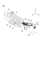
- FIG. 6 It is a perspective view which shows the manufacturing apparatus of the rice-containing resin composition which concerns on one Embodiment of this invention. It is a front view of FIG. It is a plan view of FIG. It is a figure which shows the 1st accommodation space of the 1st accommodation part which constitutes the manufacturing apparatus of the rice-containing resin composition. It is a figure which shows the plurality of rotating members arranged in the 1st accommodation space of the 1st accommodation part which constitutes the manufacturing apparatus of the rice-containing resin composition of FIG. It is a flowchart which shows the manufacturing method of the rice-containing resin composition which concerns on one Embodiment of this invention. It is an image which shows the evaluation about the rice-containing resin composition which concerns on Example. 6 is a photograph of the resin compositions of Example 1 and Comparative Examples 1, 2, 3 and 4 taken on black paper. The resin compositions of Example 1, Comparative Examples 1, 2, 3 and 4 are shown in order from the left side of the photograph.
- FIGS. 1 to 5 are diagrams provided for explaining the twin-screw kneading device 100 according to the embodiment of the present invention.
- the rice-containing resin composition according to the present embodiment can be used as a packaging bag such as a plastic shopping bag that can be obtained at a supermarket or the like.
- the rice-containing resin composition is suitable for inflation processing and can be produced by the biaxial kneading apparatus 100 shown in FIGS. 1 to 5.
- the rice-containing resin composition produced by the twin-screw kneading apparatus 100 according to the present embodiment contains rice flour, a resin (preferably polyolefin), and a compatibilizer.
- polystyrene resin examples include low-density polyethylene (LDPE), linear low-density polyethylene (LLDPE), high-density polyethylene (HDPE) or polypropylene (PP), ethylene-vinyl acetate copolymer (EVA), and ethylene-ethyl acrylate.
- LDPE low-density polyethylene
- LLDPE linear low-density polyethylene
- HDPE high-density polyethylene
- PP polypropylene
- EVA ethylene-vinyl acetate copolymer
- EVA ethylene-ethyl acrylate
- polyethylene-based copolymers such as polymer (EEA).
- LLDPE linear low density polyethylene
- LLDPE linear polyethylene copolymer having a density of 0.89 to 0.925 (JIS K6890-1: 2000).
- LLDPE has 10-30 branched chains.
- the ⁇ -olefin constituting LLDPE for example, 1-butene, 1-he
- rice bran As a raw material for rice flour, polished rice, old rice, ginjo rice, rice bran (medium white powder), etc., which have a ⁇ structure (crystal structure), are suitable.
- rice bran is often discarded in the process of milling rice, so using rice bran as rice flour has a low environmental load and is ecological, and is also suitable from the viewpoint of life cycle assessment.
- the rice flour is put into the apparatus in an air-dried state.
- the air-dried state is a state in which a material placed in the atmosphere (rice flour in the present application) reduces moisture by natural drying and maintains an equilibrium with the humidity in the atmosphere.
- the water content of the rice flour is 8 to 16% by weight, 10 to 14% by weight, or 11 to 13% by weight.
- the air-dried rice flour charged into the manufacturing apparatus is composed of a ⁇ structure (crystal structure). Then, the rice flour having a ⁇ structure (crystal structure) is kneaded in the apparatus of the manufacturing apparatus in the presence of (charged) water.
- the manufacturing apparatus preferably includes one or more side feeders and a side vent vacuum stuffer (SVS). With this configuration, it is possible to obtain a rice-blended polyolefin resin composition in which rice is finely and uniformly mixed in a polyolefin matrix while ensuring stability in production.
- SVS side vent vacuum stuffer
- the suitable blending amount (absolute dry weight) of the rice flour to be added is 100, which is the total amount of materials other than water (polyolefin, compatibilizer, rice flour, etc.) charged into the production apparatus. It is appropriate that the range is 40 to 60 parts by weight, 40 to 50 parts by weight, or 45 to 55 parts by weight with respect to the parts by weight.
- the polyolefin resin matrix of this film-molded product contains a large-grained blended rice.
- the powder is unevenly distributed.
- the film thickness of the obtained film molded product is non-uniform, cracks and pinholes are generated during the stretching process, so that there is a limit to thinning the film, and the mechanical properties of the film after molding are significantly inferior. Therefore, there was a problem that a good quality film molded product could not be obtained.
- a high-quality film-molded product can be obtained because the starch structure of rice blended in the polyolefin resin is pregelatinized so as to have an ⁇ structure.
- a saturated carboxylic acid, an unsaturated carboxylic acid or a derivative thereof is used as the compatibilizer.
- the saturated carboxylic acid include succinic anhydride, succinic acid, phthalic anhydride, phthalic acid, tetrahydrophthalic anhydride, adipic anhydride and the like.
- the unsaturated carboxylic acid include maleic acid, maleic anhydride, nadic acid anhydride, itaconic acid, itaconic anhydride, citraconic acid, citraconic anhydride, sorbic acid, acrylic acid and the like.
- a metal salt, an amide, an imide, an ester or the like of the unsaturated carboxylic acid can be used.
- a polyolefin resin modified with an unsaturated carboxylic acid or a derivative thereof can be used. This is obtained by heating and mixing a polyolefin, an unsaturated carboxylic acid or a derivative thereof, and a radical generator in the presence or absence of a solvent.
- the addition amount of the unsaturated carboxylic acid or its derivative is preferably 0.1 to 15% by weight, particularly preferably 1 to 10% by weight.
- the compatibilizer used in the present invention a polyolefin resin modified with an unsaturated carboxylic acid having no odor and a low acidity or a derivative thereof is preferable.
- the suitable blending amount of the compatibilizer is 0 with respect to 100 parts by weight of the total amount of materials other than water (polyolefin, compatibilizer, rice flour, etc.) charged into the manufacturing apparatus. It is appropriate that the range is 2 to 20 parts by weight, 0.5 to 10 parts by weight, or 1 to 5 parts by weight.
- Rrotede MG-440P manufactured by Riken Vitamin Co., Ltd.
- MG-441P manufactured by Riken Vitamin Co., Ltd.
- MG-250P manufactured by Riken Vitamin Co., Ltd.
- Umex 1001 manufactured by Sanyo Kasei Co., Ltd.
- a suitable blending amount of water is a total amount of 100 weights of materials other than water (polyolefin, compatibilizer, rice flour, etc.) charged into the production apparatus. It is appropriate that the range is 0.1 to 20 parts by weight, 1 to 20 parts by weight, or 3 to 15 parts by weight (Example: 8 parts by weight). Therefore, in one embodiment of the present invention, the amount of water added is 0.1 to 20 parts by weight with respect to 100 parts by weight of the material.
- the rice flour in an air-dried state and the material containing the resin are kneaded in the presence of the added water to pregelatinize the rice flour in the rice-containing resin composition manufacturing apparatus.
- the rice flour will be more evenly dispersed.
- agglomerates in the material can be suppressed, and coloring of the material can also be suppressed, and as a result, processing characteristics in molding, particularly inflation molding, are improved.
- the water content in the rice-containing resin composition is 2000% by weight or less, 1000% by weight or less, or 500% by weight or less.
- the amount of such water shall mean a value measured by a coulometric titration method in a Karl Fischer water measuring device.
- the MFR (melt flow rate (190 ° C., 2.16 kgf)) of the rice-containing resin composition is 1 (g / 10 min) or more and less than 10 (g / 10 min), 1 to 6 (g). / 10min), 1 to 5 (g / 10min), or 1 to 3 (g / 10min). Further, even if it is 4 to 6 (g / 10 min), it is generally good.
- the biaxial kneading device 100 includes a first accommodating unit 10, a charging unit 20, a rotating unit 30, a dehydrating unit 50, a first degassing unit 60, and a second degassing unit. It has a unit 70, a discharge unit 80, a cooling unit 90, and a cutting unit 110.
- X is a direction in which the rotation axis of the rotating portion 30 described later extends, and is defined as a longitudinal direction X.
- Y corresponds to the width direction of the first accommodating portion 10 intersecting the longitudinal direction X, and is defined as the width direction Y.
- Z is a direction that intersects the longitudinal direction X and the width direction Y, and is the height direction Z. The details will be described below.
- the first accommodating portion 10 forms a first accommodating space S1 for accommodating a material containing air-dried rice flour and a resin together with water.
- the first accommodating portion 10 is long so as to extend in the longitudinal direction X of the space in which the biaxial kneading device 100 is installed.
- the first accommodating portion 10 forms a first accommodating space S1 accommodating a plurality of rotating members 31, 32, 33, 34, 35, 36, 37, 38, 39, 41, 42 constituting the rotating portion 30. It is configured in.
- the first accommodation space S1 formed by the first accommodation unit 10 is configured to be continuous from directly below the charging unit 20 to a portion connected to the second degassing unit 70.
- the first accommodation space S1 has a shape such that the inner peripheral portion of the cross section is a combination of two arcs so that two rotation axes of the rotation member of the rotation unit 30 are provided in the present embodiment. It is composed.
- the first accommodating portion 10 may be provided with a heating device (not shown) such as a heater for adjusting the temperature of the first accommodating space S1.
- a plurality of the above-mentioned heaters can be arranged, for example, in the longitudinal direction X so that the temperature can be adjusted for each specific section of the rotating member described later in the longitudinal direction X of the first accommodating space S1 of the first accommodating portion 10.
- the charging unit 20 includes a hopper capable of charging the above-mentioned materials and water into the first accommodation space S1.
- the hopper of the charging section 20 is formed in a funnel shape so that the rice flour, resin, and water described above can be charged.
- the rotating portion 30 is rotatably arranged in the first accommodation space S1.
- the rotating portion 30 is configured to arrange a plurality of rotating members 31 to 39, 41, 42 side by side along the rotation axis with the direction parallel to the longitudinal direction X as the rotation axis.
- the rotating members 31 to 39, 41, and 42 are provided side by side in two axes along the width direction Y.
- the rotating member 31 is the first screw
- the rotating member 32 is the first paddle
- the rotating member 33 is the second screw
- the rotating member 34 is the second paddle
- the rotating member 35 is the fourth screw
- the rotating member 41 is the first screw.
- the 6-screw and the rotating member 42 correspond to the 7th screw. Each rotating member will be described in detail below.
- the rotating member 31 is arranged directly under the hopper of the charging unit 20 in the first accommodation space S1 of the first accommodation unit 10.
- the rotating member 31 is configured to form a screw.
- the portion of the first accommodation space S1 in which the rotating member 31 is arranged is referred to as a material charging section into which the material and water are charged.
- rotating members 32, 33 As shown in FIG. 5, the rotating member 32 is provided adjacent to the rotating member 31 on the downstream side of the rotating member 31 of the first accommodation space S1.
- the rotating member 32 is configured to arrange the plate-shaped members side by side along the rotation axis.
- the rotating member 32 is arranged between the rotating member 31 and the rotating member 33.
- the rotating member 33 is provided adjacent to the rotating member 32 on the downstream side of the rotating member 32 of the first accommodation space S1.
- the rotating member 33 is configured to form a screw in the same manner as the rotating member 31.
- the rotating member 33 has a shallower spiral groove than the rotating member 31.
- the rotating member 33 is configured so that the difference between the outermost circumference and the innermost circumference in the radial direction of the spiral is larger than that of the rotating member 31.
- the rotating member 33 is configured so that the size of the outermost circumference is the same as that of the rotating member 31, and the innermost circumference is smaller than that of the rotating member 31.
- the portion of the first accommodation space S1 in which the rotating members 32 and 33 are arranged can be referred to as a resin melting portion that melts the resin charged from the charging unit 20.
- the rotating member 34 Similar to the rotating member 32, the rotating member 34 is arranged so that a plurality of plate-shaped members are arranged along the rotating axis, and is arranged on the downstream side of the rotating shaft in the first accommodation space S1. It is composed. Although the rotating member 34 is shown in FIG. 5 so that the plate thickness of the plate-shaped member is one type, it does not have to be one type. The rotating member 34 is formed to be thinner than the rotating member 32 so as to exert shear stress more to disperse the material and to perform uniform stirring. The portion of the first accommodation space S1 in which the rotating member 34 is arranged can be referred to as a kneading portion for kneading the materials charged from the charging unit 20.
- a dehydration section 50 is configured to be connected to the vicinity of the boundary between the rotating member 33 and the rotating member 34 in order to discharge a gas-liquid component such as water added to the above-mentioned material. Details will be described later.
- the rotating member 35 is provided adjacent to the rotating member 34 on the downstream side of the rotating member 34 in the first accommodation space S1.
- the rotating member 35 is configured to form a screw in the same manner as the rotating member 33.
- the rotating member 35 is configured so that the depth of the spiral groove is equal to that of the rotating member 33.
- the rotating member 35 is connected to a first degassing section 60 that degass the kneaded material in the first accommodating space S1. Details will be described later.
- the rotating members 36 and 37 are provided adjacent to the rotating member 35 on the downstream side of the rotating member 35 of the first accommodation space S1.
- the rotating members 36 and 37 are configured to arrange plate-shaped members in the same manner as the rotating members 32.
- the rotating members 36 and 37 are formed with spirals having small undulations, and the spirals of the rotating member 36 and the rotating member 37 are configured to rotate in different directions.
- the rotating members 38 and 39 are provided adjacent to the rotating member 37 on the downstream side of the rotating member 37 of the first accommodation space S1.
- the rotating members 38 and 39 are configured to form a screw in the same manner as the rotating member 33.
- the screws of the rotating members 38 and 39 have the same depth of the spiral groove as the rotating member 33.
- the rotating member 38 and the rotating member 39 are configured so that the directions of rotation of the spiral are reversed.
- the portion of the first accommodation space S1 in which the rotating members 36 to 39 are arranged can be referred to as a compression portion that compresses the material.
- the rotating member 41 is provided adjacent to the rotating member 39 on the downstream side of the rotating members 35 and 39 of the first accommodation space S1.
- the rotating member 42 is provided adjacent to the rotating member 41 on the downstream side of the rotating member 41 of the first accommodation space S1.
- the rotating members 41 and 42 are configured to form a screw like the rotating member 33, and the rotating member 42 is configured to have a shorter spiral pitch than the rotating member 41.
- the rotating members 41 and 42 are connected to a second degassing section 70 that degass the material accommodated in the first accommodating space S1.
- the dehydration unit 50 is configured to discharge (dehydrate) gas-liquid components such as water generated from the material kneaded in the first storage unit 10.
- the dehydration section 50 is connected to the first accommodating section 10 from a direction intersecting the rotation axes of the rotary members 33 and 34 in the vicinity of the boundary between the rotary member 33 and the rotary member 34.
- the internal pressure of the first accommodating space S1 at the time of kneading can be configured to be a saturated vapor pressure.
- the dehydration section 50 includes a screw 51 (corresponding to a third screw), a second accommodating section 52, and a drive section 53.
- the screw 51 is configured to rotate in a direction intersecting the rotating members 31 to 39, 41, and 42 so as to form a pair.
- the drive unit 53 is configured to include a motor for rotating the screw 51.
- the second accommodating portion 52 is connected to the first accommodating portion 10 and includes a housing provided with a second accommodating space S2 for accommodating the screw 51.
- the second accommodating portion 52 discharges the water generated in the first accommodating space S1 from the second accommodating space S2.
- the second accommodating portion 52 is provided with an opening (not shown) capable of discharging the water generated in the first accommodating space S1.
- the opening can be provided in the upper part of the second accommodating portion 52 or the like.
- the first degassing unit 60 is configured to be connected to the vicinity of the rotating member 35 in the first accommodating unit 10. As shown in FIG. 5, the first degassing unit 60 includes a screw 61 (corresponding to a fifth screw), a third accommodating unit 62, and a drive unit 63.
- the screws 61 rotate in a direction intersecting the rotation axes of the rotating members 31 to 39, 41, and 42, and are configured to form a pair.
- the drive unit 63 is configured to include a motor or the like for rotationally driving the screw 61, similarly to the dehydration unit 50.
- the third accommodating portion 62 is connected to the first accommodating portion 10 in the vicinity of the rotating member 35, and includes a housing provided with a third accommodating space S3 for accommodating the screw 61.
- the third accommodating portion 62 is connected to a vacuum pump or the like capable of sucking the gas-liquid component generated in the first accommodating space S1 via the third accommodating space S3.
- the second degassing unit 70 is configured to be connected in the vicinity of the rotating member 41 arranged in the first accommodating unit 10. As shown in FIG. 5, the second degassing unit 70 includes a screw 71 (corresponding to the eighth screw), a fourth accommodating unit 72, and a drive unit 73.
- the screw 71 is configured to rotate in a direction intersecting the rotation axes of the rotating members 31 to 39, 41, and 42 so as to form a pair.
- the drive unit 73 is configured to include a motor or the like for rotationally driving the screw 71, similarly to the first degassing unit 60.
- the fourth accommodating portion 72 is connected to the first accommodating portion 10 in the vicinity of the rotating member 41, and includes a housing provided with a fourth accommodating space S4 for accommodating the screw 71.
- the fourth accommodating portion 72 is connected to a vacuum pump or the like capable of sucking the gas-liquid component generated in the first accommodating space S1 via the fourth accommodating space S4.
- the second accommodating portion 52, the third accommodating portion 62, and the fourth accommodating portion 72 are simplified and shown in FIG. 5 for convenience.
- discharge unit 80 As shown in FIG. 1 and the like, the discharge unit 80 is provided adjacent to the outside on the downstream side of the first accommodating unit 10. The discharge unit 80 is provided to form the degassed material in the first accommodation space S1 of the first accommodation unit 10 in a string shape. In the present embodiment, the discharge unit 80 is provided with a plurality of hole shapes provided at an end portion of the first accommodation unit 10 in the longitudinal direction X and at a portion connecting the first accommodation space S1 of the first accommodation unit 10 and the outside. It is configured to be provided with a member. The discharge unit 80 can be heated by providing a heating device such as a heater in the same manner as the rotating members 31 to 39, 41, 42 and the like arranged in the first accommodating unit 10.
- a heating device such as a heater
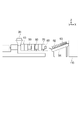
- the cooling unit 90 is provided to cool the string-shaped material discharged from the first accommodating unit 10. As shown in FIG. 1, the cooling unit 90 includes a conveyor 91, a liquid supply unit 92, and a gas supply unit 93.
- the conveyor 91 is provided adjacent to the discharge unit 80. As shown in FIG. 2, the conveyor 91 is configured to convey the material discharged from the discharge unit 80 to the cutting unit 110. As shown in FIG. 2, in the present embodiment, the conveyor 91 is configured to extend along an oblique direction inclined from the longitudinal direction X toward the positive direction in the height direction Z. However, if the extending direction of the conveyor 91 is an example and the material can be conveyed to the cutting portion 110, the specific conveying direction of the conveyor is not limited to FIG. 2 and the like.
- the liquid supply unit 92 is configured to supply cooling water having a relatively low temperature to the material conveyed on the conveyor 91.
- the liquid supply unit 92 is configured by arranging a plurality of injection nozzles connected to the cooling water supply source by a hose or the like in the transport direction of the conveyor 91.
- the gas supply unit 93 is configured to supply a gas such as air adjusted to a predetermined temperature to the material transported on the conveyor 91.
- the gas supply unit 93 is configured to include a duct (not shown) and a blower connected to the duct and capable of injecting gas toward the material on the conveyor 91.
- the cutting section 110 is configured to cut the material discharged from the discharging section 80 and cooled by the cooling section 90 to a predetermined length.
- the cutting portion 110 can include a feed roller 111 for feeding the material as shown in FIG. 1, and a cutting roller 112 provided with a blade for cutting the fed material. Further, the cooled material can be subjected to a drying step in equipment such as a chamber for drying (which can be called a drying unit).
- FIG. 6 is a flowchart showing a method for producing a rice-containing resin composition according to an embodiment of the present invention.
- the air-dried rice flour, the above-mentioned resin, the compatibilizer, and water are charged from the hopper of the charging unit 20 (ST1).
- the amount of water to be added can be 0.1 to 20 parts by weight with respect to the absolute dry mass part (100 parts by weight) of rice flour.
- the rotating members 31, 39, 41, and 42 arranged in the first accommodation space S1 of the first accommodation unit 10 can be set to a state of being heated to a predetermined temperature.
- the resin and water charged from the hopper of the charging unit 20 are sent to the rotating member 31 and conveyed to the rotating members 32 and 33 corresponding to the resin melting unit.
- the above-mentioned materials are mixed with water by the rotating members 32 and 33 in a state of being heated to about 200 ° C. and melted (ST2).
- the rice flour contained in the material is mixed with water in a heated state to initiate pregelatinization.
- the material is sent to the rotating member 34 corresponding to the kneading portion, and kneading is performed (ST3).
- the material is dispersed and agitated by forming the rotating member 34 thinner than the rotating member 32 corresponding to the resin melting portion as described above.
- the material that has passed through the rotating member 34 is further sent to the rotating member 35.
- the dehydrating unit 50 when the material is sent from the rotating member 33 to the rotating member 34, the water contained in the material is dehydrated by the dehydrating unit 50. At this time, as the screw 51 rotates near the entrance of the dehydration section 50, the solid component of the material is sent to the downstream side while remaining in the first storage space S1, and the gas-liquid component such as water is transferred to the second storage section 52. It is discharged to some extent from the opening.
- the material is sent to the downstream side by the rotating member 35, and the gas-liquid component of the material is further discharged by the first degassing unit 60 (ST4).
- the first degassing section 60 is connected to a pump or the like and the gas-liquid component of the material is sucked, while the solid component of the material remains in the first accommodating space S1 by the screw 61, and the rotating member 36 corresponding to the compression section. Sent to ⁇ 39.
- the material is sent back to the upstream side and then sent to the downstream side at the positions of the rotating members 37 and 39, so that the compression process is performed so that the density of the material is increased. It is done (ST5).
- the material that has passed through the rotating members 36 to 39 is further sent toward the discharging unit 80 at the rotating members 41 and 42.
- the gas-liquid component of the material is further sucked and degassed at the position of the rotating member 41 by a pump or the like (ST6).
- the material is discharged to the outside of the first accommodation space S1 in the form of a plurality of strings in the discharge portion 80 while the feed rate is increased by the rotating member 42 as compared with the rotating member 41.
- the string-shaped material is conveyed toward the cutting unit 110 by the conveyor 91. During this time, the material is cooled by being sprayed with cooling water by the liquid supply unit 92 and then cooled by being exposed to the cooling air in the gas supply unit 93 (ST7).
- the string-shaped material that has passed through the cooling unit 90 is conveyed by the feed roller 111 and cut to a predetermined length by the cutting roller 112 (ST8).
- the material cut by the cutting portion 110 is stretched into a flat surface, and by undergoing a drying step (ST9), the rice-containing resin composition can be formed into a shape suitable for molding into the above-mentioned plastic shopping bag or the like.
- the method for producing a rice-containing resin composition according to the present embodiment is configured to knead a material containing rice flour in an air-dried state and a resin in the presence of added water.
- the above-mentioned materials include a compatibilizer. This can promote uniform mixing of materials such as rice flour and resin.
- a rice-containing resin composition can be produced (manufactured).
- rice flour is configured to be pregelatinized in the manufacturing process. Thereby, the rice flour can be mixed with the above-mentioned resin to produce (manufacture) a rice-containing resin composition.
- the amount of water added in the above-mentioned manufacturing method is configured to be 0.1 to 20 parts by weight with respect to 100 parts by weight of the material.
- rice flour can be kneaded with a resin to produce (manufacture) a rice-containing resin composition.
- the twin-screw kneading device 100 for kneading, the above-mentioned material containing rice flour can be kneaded to produce (manufacture) a resin composition.
- the twin-screw kneading device 100 includes a dehydrating unit 50 for dehydrating. As a result, it is possible to remove gas-liquid components such as water that are unnecessary when the resin composition is produced (manufactured) from rice flour.
- the dehydration section 50 is configured to perform dehydration under saturated steam pressure. Therefore, even if a large amount of water is added to the rice flour, unnecessary water and other gas-liquid components can be removed.
- the twin-screw kneading device 100 is configured to include a first degassing section 60 and a second degassing section 70 as two degassing sections. Therefore, when the rice flour and the resin are kneaded using a relatively large amount of water, the first degassing section 60 and the second degassing section 70 are used to obtain a gas solution such as water that is unnecessary for the resin composition. Ingredients can be removed.
- the biaxial kneading device 100 has a first accommodating portion 10, a charging portion 20, and a rotating portion 30.
- the first accommodating portion 10 forms a first accommodating space S1 capable of accommodating materials and water.
- the charging unit 20 is configured so that materials and water can be charged in the first storage space S1.
- the rotating portion 30 is rotatably arranged in the first accommodation space S1, and a plurality of rotating members 31 to 39, 41, 42 are arranged side by side along the rotation axis of the rotating members 31 to 39, 41, 42.
- the rotating portion 30 is provided with two rotating shafts on which the rotating members 31 to 39, 41, and 42 rotate.
- the rotating members 31 to 39, 41, and 42 have a spiral shape, and the rotating member 31 is arranged directly under the charging portion 20 and is arranged on the downstream side of the rotating shaft with respect to the rotating member 31, and is spiraled with respect to the rotating member 31.
- a rotating member 33 having a shallow groove is provided.
- the rotating members 31 to 39, 41, 42 are arranged between the rotating member 31 and the rotating member 33, and the rotating member 32 in which the plate-shaped members are arranged side by side on the rotating shaft and the rotating member 32 downstream of the rotating member 33.
- a plate-shaped rotating member 34 arranged on the side is provided.
- a dehydration section 50 is connected in the vicinity of the rotating member 33 and the rotating member 34.
- the dehydration section 50 includes a screw 51 and a second accommodating section 52.
- the screws 51 rotate with the rotation axis in a direction parallel to the width direction Y intersecting the rotation axis, and are configured to form a pair.
- the second accommodating portion 52 includes a second accommodating space S2 accommodating the screw 51, and is connected to the first accommodating portion 10 to provide an opening capable of discharging the water generated in the first accommodating space S1. With this configuration, it is possible to remove unnecessary gas-liquid components such as unnecessary water contained in the material while leaving the solid component contained in the material in the first storage space S1 of the first storage unit 10.
- the rotating members 31 to 39, 41, 42 include a rotating member 35 provided on the downstream side of the rotating member 34 in the first accommodation space S1.
- a first degassing unit 60 is connected in the vicinity of the rotating member 35.
- the first degassing unit 60 includes a screw 61 and a third accommodating unit 62.
- the screws 61 rotate with the rotation axis in a direction parallel to the direction intersecting the rotation axes of the rotation members 31 to 39, 41, 42, and are configured to form a pair.
- the third accommodating portion 62 includes a third accommodating space S3 accommodating the screw 61, is connected to the first accommodating portion 10, and is connected to a pump or the like capable of discharging the gas generated in the first accommodating space S1 by suction. .. With this configuration, it is possible to further discharge unnecessary gas-liquid components contained in the material while leaving the solid component of the material in the first accommodation space S1 as in the dehydration section 50.
- the rotating members 31 to 39, 41, 42 include a rotating member 41 provided on the downstream side of the rotating member 35 in the first accommodation space S1 and a rotating member 42 provided adjacent to the rotating member 41. ..
- a second degassing unit 70 is connected in the vicinity of the rotating member 41.
- the second degassing section 70 includes a screw 71 and a fourth accommodating section 72.
- the screw 71 is configured to rotate in a direction parallel to the direction intersecting the rotation axis of the rotating member 41 with the rotation axis as a rotation axis so as to form a pair.
- the fourth accommodating portion 72 includes a fourth accommodating space S4 accommodating the screw 71, is connected to the first accommodating portion 10, and is connected to a pump capable of discharging the gas generated in the first accommodating space S1 by suction.
- a pump capable of discharging the gas generated in the first accommodating space S1 by suction.
- FIG. 7 is an image relating to the evaluation of the embodiment.
- FIG. 8 is a photograph of the resin compositions of Example 1, Comparative Examples 1, 2, 3 and 4 taken on black paper, and in order from the left side of the photograph, Example 1, Comparative Examples 1, 2, 3 and 4 is the resin composition.
- the MFR (g / 10 min), water content, and the degree of aggregation of starch contained in the rice-containing resin composition when the rice-containing resin composition was produced were confirmed according to the four specifications described later.
- the rice-containing resin composition was A: LLDPE (prime polymer evolve (registered trademark) sp4030), B: maleic anhydride-modified polypropylene (RIKEN vitamin MG-440P), C: rice flour (Niigata Kenbei medium white powder, water content). 12%), D: Distilled water was used.
- a biaxial kneading device 100 that rotates in the same direction, or a vacuum degassing device that does not have the first degassing section 60 and the second degassing section 70 was used.
- the L / D of the rotating member was set to 50.
- the rotating member of the rotating portion 30 the above-mentioned rotating members 31 to 39, 41, 42 were used.
- the ratio of the rotating members 32, 34 (kneading block ratio) to the total length of the rotating members 31 to 39, 41, 42 in the longitudinal direction X was set to 25%. Further, the distilled water was supplied from the hopper of the charging unit 20 to the first accommodation space S1 by using a tube pump.
- the rotation speed of the rotating members 31 to 39, 41, 42 was set to 280 rpm. Then, the portion corresponding to the charging portion in the first accommodation space S1 was heated to 80 ° C., the portion corresponding to the resin melting portion was heated to 160 ° C., and the portion corresponding to the kneading portion was heated to 200 ° C. Further, the connection portion between the first degassing portion 60 and the second degassing portion 70 in the first accommodation space S1 was heated to 180 ° C., the portion corresponding to the compression portion was heated to 190 ° C., and the discharge portion 80 was heated to 190 ° C.
- Example 1 and Comparative Examples 1, 2, 3 and 4 were prepared as comparison targets.
- Example 1 the above-mentioned biaxial kneading device 100 was used to generate a resin composition while adding distilled water to the above-mentioned material.
- Comparative Example 1 the above-mentioned biaxial kneading device 100 was used, but the materials were composited without adding distilled water.
- Comparative Example 2 the materials were composited using the vacuum degassing device not provided with the first degassing section 60 and the second degassing section 70 constituting the above-mentioned biaxial kneading device 100.
- Comparative Example 4 is based on Example 1 of JP-A-2005-330402, and rice milled soaked in distilled water for 30 minutes without adding distilled water is used instead of rice flour, and the rest is the same as in Example 1.
- the melt flow rate (MFR: g / 10 min), the water content (ppm) of the resin composition, and the degree of starch aggregation in the resin composition were confirmed in Examples 1 and 1 and 2 described above.
- the agglomeration of starch the resin composition sent from the cut portion 110 was visually stretched at 170 ° C. by hot pressure molding by hot pressing and stretched in a flat shape, and it was confirmed whether or not the agglomeration of starch was observed.
- the sheet on the left side in FIG. 7 is a specification in which agglomeration of starch is not observed, and the sheet on the right side is a specification in which agglomeration of starch is observed.
- Table 1 shows the confirmation results of the composition, MFR, moisture, and starch aggregation of A, B, C, and D described above.
- ⁇ The degree of coloring is strong and the transparency is low.
- Comparative Example 1 As shown in Table 1, in Comparative Example 1, the above-mentioned material bite into the twin-screw kneading device 100 was poor, the pregelatinization of rice flour was insufficient, the agglomeration of the material was not eliminated, and the material remained in a non-uniform state. .. Further, in Comparative Example 1, a large amount of generated water was generated due to carbonization and decomposition by heat, stable measurement of water content could not be performed, and the composition could not be sufficiently dried.
- Comparative Example 2 the MFR became relatively high by adding distilled water. Further, when the MFR was measured in Comparative Example 2, only the resin component having insufficient kneading flowed out, and the heat flow became unstable. Further, as is clear from FIG. 8, Comparative Example 2 has excessive aggregation. Further, in Comparative Example 3, although the MFR was generally good, the water content was high and the starch aggregation was less than that in Comparative Examples 1 and 2, but it was observed. Further, as is clear from FIG. 8, Comparative Example 4 has less aggregation than Comparative Examples 1, 2 and 3, but the presence of aggregation increases the number of white spots and results in deterioration of transparency. ing. It was
- Example 1 the MFR and water content were within the range considered to be good, and no starch aggregation was observed. Therefore, the rice-containing resin composition produced by the method according to the present embodiment had good specifications. I was able to confirm that it was there.
- 100 Biaxial kneading device (manufacturing device for rice-containing resin composition), 10 1st containment unit, 20 input section, 30 rotating parts, 31 Rotating member (1st screw), 32 Rotating member (1st paddle), 33 Rotating member (second screw), 34 Rotating member (second paddle), 35 Rotating member (4th screw), 41 Rotating member (6th screw), 42 Rotating member (7th screw), 50 dehydration part, 51 screw (3rd screw), 52 Second containment unit, 60 1st degassing part, 61 screw (fifth screw), 62 Third containment unit, 70 Second degassing part, 71 screw (8th screw), 72 4th containment unit, S1 1st accommodation space, S2 second accommodation space, S3 3rd accommodation space, S4 4th accommodation space, X longitudinal direction, Y width direction (direction that intersects the axis of rotation).
Landscapes
- Chemical & Material Sciences (AREA)
- Health & Medical Sciences (AREA)
- Chemical Kinetics & Catalysis (AREA)
- Medicinal Chemistry (AREA)
- Polymers & Plastics (AREA)
- Organic Chemistry (AREA)
- Engineering & Computer Science (AREA)
- Mechanical Engineering (AREA)
- Processing And Handling Of Plastics And Other Materials For Molding In General (AREA)
- Extrusion Moulding Of Plastics Or The Like (AREA)
- Processes Of Treating Macromolecular Substances (AREA)
- Compositions Of Macromolecular Compounds (AREA)
Priority Applications (6)
| Application Number | Priority Date | Filing Date | Title |
|---|---|---|---|
| CN202080107680.0A CN116723890A (zh) | 2020-12-25 | 2020-12-25 | 含米树脂组合物的制造方法及双轴混炼装置 |
| BR112023012664A BR112023012664A2 (pt) | 2020-12-25 | 2020-12-25 | Método de produção de composição de resina contendo arroz, e amassador de parafuso duplo |
| PCT/JP2020/048869 WO2022137548A1 (ja) | 2020-12-25 | 2020-12-25 | 米含有樹脂組成物の製造方法および二軸混練装置 |
| JP2022554745A JP7191435B2 (ja) | 2020-12-25 | 2020-12-25 | 米含有樹脂組成物の製造方法および二軸混練装置 |
| JP2022147029A JP7442218B2 (ja) | 2020-12-25 | 2022-09-15 | 米含有樹脂組成物の製造方法および二軸混練装置 |
| JP2022191220A JP7442223B2 (ja) | 2020-12-25 | 2022-11-30 | 米含有樹脂組成物の製造方法および二軸混練装置 |
Applications Claiming Priority (1)
| Application Number | Priority Date | Filing Date | Title |
|---|---|---|---|
| PCT/JP2020/048869 WO2022137548A1 (ja) | 2020-12-25 | 2020-12-25 | 米含有樹脂組成物の製造方法および二軸混練装置 |
Publications (1)
| Publication Number | Publication Date |
|---|---|
| WO2022137548A1 true WO2022137548A1 (ja) | 2022-06-30 |
Family
ID=82158009
Family Applications (1)
| Application Number | Title | Priority Date | Filing Date |
|---|---|---|---|
| PCT/JP2020/048869 Ceased WO2022137548A1 (ja) | 2020-12-25 | 2020-12-25 | 米含有樹脂組成物の製造方法および二軸混練装置 |
Country Status (4)
| Country | Link |
|---|---|
| JP (3) | JP7191435B2 (https=) |
| CN (1) | CN116723890A (https=) |
| BR (1) | BR112023012664A2 (https=) |
| WO (1) | WO2022137548A1 (https=) |
Cited By (2)
| Publication number | Priority date | Publication date | Assignee | Title |
|---|---|---|---|---|
| JP7371978B1 (ja) | 2022-12-27 | 2023-10-31 | 株式会社バイオマスレジンホールディングス | バイオマスマスターバッチ |
| CN117582843A (zh) * | 2024-01-18 | 2024-02-23 | 回头客食品集团股份有限公司 | 一种原料加工用搅拌混合设备 |
Citations (6)
| Publication number | Priority date | Publication date | Assignee | Title |
|---|---|---|---|---|
| JP2002505367A (ja) * | 1998-03-05 | 2002-02-19 | スタンダード スターチ, エル.エル.シー. | モロコシ粉ベースの生分解性組成物、これから作られた成形品、およびこれらの成形品の作製方法 |
| WO2005087857A1 (ja) * | 2004-03-10 | 2005-09-22 | Agri Future Joetsu Co., Ltd. | 澱粉配合樹脂組成物、その成形品及びその製造方法 |
| JP2013006171A (ja) * | 2011-05-20 | 2013-01-10 | Nitto Denko Corp | 混練機 |
| JP2015065829A (ja) * | 2013-09-26 | 2015-04-13 | 株式会社白石バイオマス | 米糠フィルム及びその製造方法 |
| JP2016064501A (ja) * | 2014-05-22 | 2016-04-28 | 国立大学法人九州工業大学 | バイオマスナノ繊維の製造方法およびバイオマスナノ繊維・高分子樹脂複合体の製造方法 |
| JP2020521432A (ja) * | 2017-06-01 | 2020-07-27 | ウェンガー マニュファクチュアリング アイエヌシー. | 高比機械エネルギー押出しスクリュー組立体 |
Family Cites Families (10)
| Publication number | Priority date | Publication date | Assignee | Title |
|---|---|---|---|---|
| JPS5856818A (ja) * | 1981-09-30 | 1983-04-04 | Unitika Ltd | ガラス繊維強化熱可塑性樹脂の製造方法 |
| JPS59101318A (ja) * | 1982-11-30 | 1984-06-11 | Unitika Ltd | ガラス繊維強化熱可塑性樹脂の製造方法 |
| JP2001162671A (ja) | 1999-12-09 | 2001-06-19 | Hitachi Zosen Corp | 再生樹脂用二軸押出機 |
| JP4279975B2 (ja) * | 2000-05-16 | 2009-06-17 | 株式会社日本製鋼所 | 二軸脱水押出機による脱溶液方法および二軸脱水押出機 |
| JP2005255743A (ja) * | 2004-03-10 | 2005-09-22 | Agri Future Joetsu Co Ltd | ポリオレフィン樹脂組成物、その製造方法、その成形品及びこの成形品の成形方法 |
| JP4746288B2 (ja) * | 2004-07-09 | 2011-08-10 | アグリフューチャー・じょうえつ株式会社 | 澱粉配合樹脂組成物の製造方法 |
| JP4448510B2 (ja) | 2006-12-26 | 2010-04-14 | 株式会社日本製鋼所 | 廃プラスチックの処理装置 |
| JP5832733B2 (ja) * | 2010-09-17 | 2015-12-16 | 富士フイルム株式会社 | ポリエステルフィルムの製造方法 |
| US10434483B2 (en) | 2017-02-15 | 2019-10-08 | Wenger Manufacturing Inc. | High thermal transfer hollow core extrusion screw assembly |
| JP6750824B1 (ja) | 2020-03-19 | 2020-09-02 | 正雄 王 | 生分解性植物繊維原料粒の組成物、及びその製造方法 |
-
2020
- 2020-12-25 WO PCT/JP2020/048869 patent/WO2022137548A1/ja not_active Ceased
- 2020-12-25 BR BR112023012664A patent/BR112023012664A2/pt not_active Application Discontinuation
- 2020-12-25 JP JP2022554745A patent/JP7191435B2/ja active Active
- 2020-12-25 CN CN202080107680.0A patent/CN116723890A/zh active Pending
-
2022
- 2022-09-15 JP JP2022147029A patent/JP7442218B2/ja active Active
- 2022-11-30 JP JP2022191220A patent/JP7442223B2/ja active Active
Patent Citations (6)
| Publication number | Priority date | Publication date | Assignee | Title |
|---|---|---|---|---|
| JP2002505367A (ja) * | 1998-03-05 | 2002-02-19 | スタンダード スターチ, エル.エル.シー. | モロコシ粉ベースの生分解性組成物、これから作られた成形品、およびこれらの成形品の作製方法 |
| WO2005087857A1 (ja) * | 2004-03-10 | 2005-09-22 | Agri Future Joetsu Co., Ltd. | 澱粉配合樹脂組成物、その成形品及びその製造方法 |
| JP2013006171A (ja) * | 2011-05-20 | 2013-01-10 | Nitto Denko Corp | 混練機 |
| JP2015065829A (ja) * | 2013-09-26 | 2015-04-13 | 株式会社白石バイオマス | 米糠フィルム及びその製造方法 |
| JP2016064501A (ja) * | 2014-05-22 | 2016-04-28 | 国立大学法人九州工業大学 | バイオマスナノ繊維の製造方法およびバイオマスナノ繊維・高分子樹脂複合体の製造方法 |
| JP2020521432A (ja) * | 2017-06-01 | 2020-07-27 | ウェンガー マニュファクチュアリング アイエヌシー. | 高比機械エネルギー押出しスクリュー組立体 |
Cited By (4)
| Publication number | Priority date | Publication date | Assignee | Title |
|---|---|---|---|---|
| JP7371978B1 (ja) | 2022-12-27 | 2023-10-31 | 株式会社バイオマスレジンホールディングス | バイオマスマスターバッチ |
| JP2024093227A (ja) * | 2022-12-27 | 2024-07-09 | 株式会社バイオマスレジンホールディングス | バイオマスマスターバッチ |
| CN117582843A (zh) * | 2024-01-18 | 2024-02-23 | 回头客食品集团股份有限公司 | 一种原料加工用搅拌混合设备 |
| CN117582843B (zh) * | 2024-01-18 | 2024-04-02 | 回头客食品集团股份有限公司 | 一种原料加工用搅拌混合设备 |
Also Published As
| Publication number | Publication date |
|---|---|
| JP7442223B2 (ja) | 2024-03-04 |
| BR112023012664A2 (pt) | 2023-10-03 |
| JP2023014217A (ja) | 2023-01-26 |
| JP2022174240A (ja) | 2022-11-22 |
| CN116723890A (zh) | 2023-09-08 |
| JPWO2022137548A1 (https=) | 2022-06-30 |
| JP7191435B2 (ja) | 2022-12-19 |
| JP7442218B2 (ja) | 2024-03-04 |
Similar Documents
| Publication | Publication Date | Title |
|---|---|---|
| JP6955774B2 (ja) | 疎水性を有する熱可塑性デンプン複合材料とその製造方法 | |
| JP7442223B2 (ja) | 米含有樹脂組成物の製造方法および二軸混練装置 | |
| JPS6257491B2 (https=) | ||
| CN115418083A (zh) | 一种膜袋用低成本pbat生物降解材料及其制备方法 | |
| US6143811A (en) | Method of producing compound pellets containing wood flour | |
| JP7371978B1 (ja) | バイオマスマスターバッチ | |
| JP2011005742A (ja) | 熱可塑性樹脂組成物の製造方法 | |
| KR20130000331A (ko) | 미세 지분 함유 수지조성물의 제조방법 | |
| JP2002225011A (ja) | 成形用木質系組成物及びその製造方法 | |
| JP3878623B2 (ja) | 米配合ポリオレフィン樹脂組成物、その製造方法、そのフィルム成形品及びこの成形品の成形方法 | |
| TW202534115A (zh) | 含鹵化金屬鹽之熱塑性澱粉組成物、丸粒、小片、複合體、樹脂成形物、熱塑性澱粉組成物之製造方法、丸粒或小片之製造方法、複合體之製造方法、及樹脂成形物之製造方法 | |
| JP2003531750A (ja) | 木材繊維を処理するためのツイン・スクリュー押出機およびその方法 | |
| JP2024079179A (ja) | 米含有樹脂組成物の製造方法およびその成形品の製造方法 | |
| TWI854871B (zh) | 高分子化合物的生成方法 | |
| CN1930228A (zh) | 淀粉混合树脂组合物、其成形品及其制造方法 | |
| JP2025053420A (ja) | バイオマスマスターバッチ | |
| JP7756502B2 (ja) | 樹脂複合材料の製造方法および製造装置 | |
| JP2021025030A (ja) | 澱粉配合ポリエチレン樹脂組成物およびそれを用いた包装材料 | |
| Siaotong | Effects of fiber content and extrusion parameters on the properties of flax fiber-polyethylene composites | |
| JP4970017B2 (ja) | シート又はフィルム巻取用コア | |
| JPS61266222A (ja) | 押出成形方法及びそのための装置 | |
| CN215094919U (zh) | 一种塑料制品原料加工设备 | |
| WO2023073895A1 (ja) | デンプン含有樹脂組成物、成形物、及びデンプン含有樹脂組成物の生分解速度の調整方法 | |
| JP2024004910A (ja) | バイオマス材料含有樹脂組成物の製造方法および成形品の製造方法 | |
| JP2024108995A (ja) | 澱粉含有樹脂組成物、ペレット、フレーク、樹脂成形物、澱粉含有樹脂組成物の製造方法、ペレット又はフレークの製造方法、及び樹脂成形物の製造方法 |
Legal Events
| Date | Code | Title | Description |
|---|---|---|---|
| ENP | Entry into the national phase |
Ref document number: 2022554745 Country of ref document: JP Kind code of ref document: A |
|
| WWE | Wipo information: entry into national phase |
Ref document number: 202080107680.0 Country of ref document: CN |
|
| REG | Reference to national code |
Ref country code: BR Ref legal event code: B01A Ref document number: 112023012664 Country of ref document: BR |
|
| NENP | Non-entry into the national phase |
Ref country code: DE |
|
| ENP | Entry into the national phase |
Ref document number: 112023012664 Country of ref document: BR Kind code of ref document: A2 Effective date: 20230623 |
|
| 122 | Ep: pct application non-entry in european phase |
Ref document number: 20967034 Country of ref document: EP Kind code of ref document: A1 |