WO2022131119A1 - レンズ駆動装置及びカメラモジュール - Google Patents
レンズ駆動装置及びカメラモジュール Download PDFInfo
- Publication number
- WO2022131119A1 WO2022131119A1 PCT/JP2021/045301 JP2021045301W WO2022131119A1 WO 2022131119 A1 WO2022131119 A1 WO 2022131119A1 JP 2021045301 W JP2021045301 W JP 2021045301W WO 2022131119 A1 WO2022131119 A1 WO 2022131119A1
- Authority
- WO
- WIPO (PCT)
- Prior art keywords
- accommodating recess
- holding member
- lens
- lens holding
- parting line
- Prior art date
- Legal status (The legal status is an assumption and is not a legal conclusion. Google has not performed a legal analysis and makes no representation as to the accuracy of the status listed.)
- Ceased
Links
Images


Classifications
-
- G—PHYSICS
- G02—OPTICS
- G02B—OPTICAL ELEMENTS, SYSTEMS OR APPARATUS
- G02B7/00—Mountings, adjusting means, or light-tight connections, for optical elements
- G02B7/02—Mountings, adjusting means, or light-tight connections, for optical elements for lenses
-
- G—PHYSICS
- G02—OPTICS
- G02B—OPTICAL ELEMENTS, SYSTEMS OR APPARATUS
- G02B7/00—Mountings, adjusting means, or light-tight connections, for optical elements
- G02B7/02—Mountings, adjusting means, or light-tight connections, for optical elements for lenses
- G02B7/04—Mountings, adjusting means, or light-tight connections, for optical elements for lenses with mechanism for focusing or varying magnification
-
- G—PHYSICS
- G03—PHOTOGRAPHY; CINEMATOGRAPHY; ANALOGOUS TECHNIQUES USING WAVES OTHER THAN OPTICAL WAVES; ELECTROGRAPHY; HOLOGRAPHY
- G03B—APPARATUS OR ARRANGEMENTS FOR TAKING PHOTOGRAPHS OR FOR PROJECTING OR VIEWING THEM; APPARATUS OR ARRANGEMENTS EMPLOYING ANALOGOUS TECHNIQUES USING WAVES OTHER THAN OPTICAL WAVES; ACCESSORIES THEREFOR
- G03B30/00—Camera modules comprising integrated lens units and imaging units, specially adapted for being embedded in other devices, e.g. mobile phones or vehicles
Definitions
- the present disclosure relates to a lens driving device mounted on, for example, a portable device with a camera.
- a camera module having a base, a lens holder, and a leaf spring for connecting the base and the lens holder is known (see Patent Document 1).
- a spiral groove is formed in the upper part of the inner peripheral surface of the lens holder so that the adhesive between the inner peripheral surface of the lens holder and the outer peripheral surface of the lens barrel is firmly adhered.
- the adhesive located in the spiral groove may peel off from the lens holder and rotate along the spiral groove together with the lens barrel.
- a lens driving device provided with a lens holding member capable of more firmly holding a lens body such as a lens barrel.
- the lens driving device includes a fixed-side member including a housing, a lens holding member arranged in the housing and capable of holding a lens body, and the fixed-side member for holding the lens.
- a lens driving device comprising a drive mechanism for moving the lens body with respect to the lens and the lens body being fixed to the lens holding member by an adhesive
- the lens holding member extends in the vertical direction in the optical axis direction and inwardly. It has a tubular portion on which the lens body can be arranged, and on the inner surface of the tubular portion, a parting line, which is a seam of a mold when the lens holding member is molded, is formed in the optical axis direction.
- An accommodating recess capable of accommodating the adhesive is formed, and the shape of the accommodating recess is between the lens body and the lens holding member by engaging with the shape of the adhesive accommodated in the accommodating recess. Regulate relative vertical movement.
- the lens holding member in the above-mentioned lens driving device can hold the lens body more firmly.
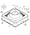
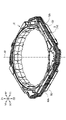
- FIG. 1A is an upward perspective view of the lens driving device 101 to which the lens body LS is attached
- FIG. 1B is an upward perspective view of the lens body LS
- FIG. 2 is an exploded perspective view of the lens driving device 101.
- X1 represents one direction of the X-axis constituting the three-dimensional Cartesian coordinate system
- X2 represents the other direction of the X-axis
- Y1 represents one direction of the Y axis constituting the three-dimensional Cartesian coordinate system
- Y2 represents the other direction of the Y axis
- Z1 represents one direction of the Z axis constituting the three-dimensional Cartesian coordinate system
- Z2 represents the other direction of the Z axis.
- the optical axis JD extends parallel to the Z axis.
- the X1 side of the lens driving device 101 corresponds to the front side (front side) of the lens driving device 101, and the X2 side of the lens driving device 101 corresponds to the rear side (rear side) of the lens driving device 101.
- the Y1 side of the lens driving device 101 corresponds to the right side of the lens driving device 101, and the Y2 side of the lens driving device 101 corresponds to the left side of the lens driving device 101.
- the Z1 side of the lens driving device 101 corresponds to the upper side of the lens driving device 101, and the Z2 side of the lens driving device 101 corresponds to the lower side of the lens driving device 101. The same applies to other figures.
- the lens driving device 101 includes a cover member 4 which is a part of the fixed side member RG.
- the cover member 4 is configured to function as a housing HS that covers each member.
- the cover member 4 is manufactured by subjecting a plate material made of a soft magnetic material such as iron to punching, drawing, and the like, and functions as a yoke.
- the cover member 4 may be manufactured by subjecting a plate material made of a non-magnetic metal such as austenitic stainless steel to a punching process, a drawing process, or the like.
- the cover member 4 has a rectangular tubular outer peripheral wall portion 4A and a rectangular annular and flat plate-shaped top plate portion 4B provided so as to be continuous with the upper end (Z1 side end) of the outer peripheral wall portion 4A.
- a substantially circular opening 4k is formed in the center of the top plate portion 4B.
- the outer peripheral wall portion 4A includes a first side plate portion 4A1 to a fourth side plate portion 4A4.
- the first side plate portion 4A1 and the third side plate portion 4A3 face each other, and the second side plate portion 4A2 and the fourth side plate portion 4A4 face each other.
- the first side plate portion 4A1 and the third side plate portion 4A3 extend perpendicularly to the second side plate portion 4A2 and the fourth side plate portion 4A4.
- the top plate portion 4B is not limited to a flat plate shape, and may have a concave portion or a convex portion.
- the lens body LS is, for example, a cylindrical lens barrel including at least one lens.
- the lens body LS has a two-stage cylindrical outer shape.
- the lens body LS is configured so that the outer peripheral surface ES of the lower cylindrical body comes into contact with the lens holding member 2 and is held by the lens holding member 2.
- the outer peripheral surface ES is formed of a smooth cylindrical surface on which threads or the like are not formed so that the lens size can be increased.
- FIG. 2 is an exploded perspective view of the lens driving device 101.
- FIG. 3A is an upward perspective view of the lens driving device 101 with the lens body LS removed
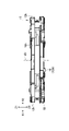
- FIG. 3B is a front view of the lens driving device 101 with the lens body LS removed.
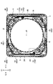
- FIG. 4A is a top view of the lens driving device 101 with the lens body LS removed
- FIG. 4B is a bottom view of the lens driving device 101 with the lens body LS removed.
- FIG. 5A is an upward perspective view of the lens driving device 101 in a state where the lens body LS, the cover member 4, and the spacer 1 are removed.
- FIG. 5B is a front view of the lens driving device 101 in a state where the lens body LS, the cover member 4, and the spacer 1 are removed.
- a dot pattern is attached to the coil 3 for clarification.
- the lens driving device 101 includes a lens holding member 2 capable of holding the lens body LS, a driving mechanism MK capable of moving the lens holding member 2 along the optical axis direction, and a lens holding member. It includes a leaf spring 6 that movably supports 2 in the optical axis direction, a fixed side member RG to which the leaf spring 6 is fixed, and a metal member 7 that provides an electrical connection to the outside.
- the optical axis direction includes the direction of the optical axis JD with respect to the lens body LS and the direction parallel to the optical axis JD.
- the drive mechanism MK includes a coil 3 wound in an octagonal ring shape, a cover member 4 also serving as an outer case provided with a rectangular tubular outer peripheral wall portion 4A, and a magnet 5.
- the magnet 5 includes a first magnet 5A and a second magnet 5B arranged to face the two sides of the coil 3.
- the fixed side member RG includes a spacer 1, a cover member 4, and a base member 18 in which a metal member 7 is embedded.
- the leaf spring 6 is an upper leaf spring 16 arranged between the lens holding member 2 and the cover member 4 (strictly speaking, a spacer 1), and a lower plate arranged between the lens holding member 2 and the base member 18. Includes spring 26.
- the lower leaf spring 26 includes a first lower leaf spring 26A and a second lower leaf spring 26B.
- the lens drive device 101 typically has a substantially rectangular parallelepiped outer shape as shown in FIG. 1A, and is mounted on an external substrate (not shown) on which an image sensor (not shown) is mounted. ..
- the external substrate, the lens driving device 101, the lens body LS mounted on the lens holding member 2, and the image pickup element mounted on the external board so as to face the lens body LS constitute a camera module.
- the coil 3 is connected to the power supply via the lower leaf spring 26, the metal member 7, and the external substrate. When a current flows through the coil 3, the drive mechanism MK generates an electromagnetic force along the optical axis direction.
- the lens driving device 101 realizes an automatic focus adjustment function by using this electromagnetic force to move the lens holding member 2 along the optical axis direction on the Z1 side (subject side) of the image pickup element. Specifically, the lens driving device 101 moves the lens holding member 2 in a direction away from the image sensor to enable macro photography, and moves the lens holding member 2 in a direction closer to the image sensor to enable infinity photography. I have to.
- FIG. 6A is an upward perspective view of the lens holding member 2
- FIG. 6B is an upward perspective view of the lens holding member 2 showing a state in which the coil 3 is wound around the lens holding member 2 of FIG. 6A
- 7A is a downward perspective view of the lens holding member 2
- FIG. 7B is a downward perspective view of the lens holding member 2 showing a state in which the coil 3 is wound around the lens holding member 2 of FIG. 7A
- 8A is a top view of the lens holding member 2
- FIG. 8B is a top view of the lens holding member 2 showing a state in which the coil 3 is wound around the lens holding member 2 of FIG. 8A.
- FIG. 9A is a right side view of the lens holding member 2 as seen from the Y1 side
- FIG. 9B is a right side view of the lens holding member 2 showing a state in which the coil 3 is wound around the lens holding member 2 shown in FIG. 9A
- Is. 9C is a left side view of the lens holding member 2 as seen from the Y2 side
- FIG. 9D is a left side view of the lens holding member 2 showing a state in which the coil 3 is wound around the lens holding member 2 shown in FIG. 9C
- Is. 10A is an enlarged view of a portion in the range R1 shown in FIG. 7B
- FIG. 10B is an enlarged view of a portion in the range R2 shown in FIG. 7B when viewed from the Y2 side.
- FIG. 11A is a bottom view of the lens driving device 101 with the metal member 7 and the base member 18 removed, and FIG. 11B further shows a first lower leaf spring 26A, a second lower leaf spring 26B, and a lens holding member.
- 2 is a bottom view of the lens driving device 101 in a state where 2 is removed.
- a dot pattern is attached to the coil 3 for clarity.
- the lens holding member 2 is manufactured by injection molding a synthetic resin such as a liquid crystal polymer (LCP). Specifically, as shown in FIG. 6A, the lens holding member 2 is formed on a tubular portion 12 formed so as to extend along the optical axis direction and on the image pickup element side (Z2 side) in the optical axis direction. Includes a flange portion (flange-shaped portion) 52. In the present embodiment, the upper half of the tubular portion 12 is formed in a substantially cylindrical shape.
- LCP liquid crystal polymer
- a housing recess SR is formed on the inner peripheral surface so that an adhesive is arranged between the inner surface SF of the tubular portion 12 and the outer peripheral surface ES (see FIG. 1B) of the lens body LS.
- 20 accommodating recesses SR are formed on the inner peripheral surface of the tubular portion 12.
- the cylindrical portion 12 is provided with pedestal portions 12d having recesses 12dh at four locations on the end surface on the subject side. Then, as shown in FIG. 5A, the inner portion 16i of the upper leaf spring 16 is placed on the pedestal portion 12d.
- a coil support portion 12j as an outer wall portion that supports the coil 3 from the inside is provided on the outer peripheral surface of the tubular portion 12.
- the coil support portion 12j has an octagonal outer shape in the top view so as to support the octagonal annular coil 3 in the top view.
- eaves portions 12h projecting outward in the radial direction so as to face the flange portion 52 in the optical axis direction are formed at four locations. Then, as shown in FIG.
- the coil 3 is supported by the coil support portion 12j and is sandwiched between the eaves portion 12h and the flange portion 52 in the optical axis direction so as to be octagonal on the outer peripheral surface of the lens holding member 2. It is mounted in a ring shape.
- the flange portion 52 protrudes radially outward from the end portion of the tubular portion 12 on the image sensor side (Z2 side).
- a coil 3 is arranged on the subject side of the flange portion 52.
- the flange portion 52 is formed with two notched portions 52k with the optical axis JD interposed therebetween.
- An extending portion 33 which is a part of the conductive wire rod constituting the coil 3, is passed through the cutout portion 52k.
- an extending portion 33A which is a part of the wire rod on the winding end side of the coil 3, is passed through one of the notch portions 52k, and one of the wire rods on the winding start side of the coil 3 is passed through the other of the cutout portion 52k.
- the extension portion 33B which is a portion, is passed through.
- the edge portion of the flange portion 52 forming the notch portion 52k is configured to be rounded (not angular). This is to prevent disconnection of the wire rod constituting the coil 3 in contact with the edge portion.
- the flange portion 52 has four round convex protrusions 2t protruding downward (Z2 direction) from the surface on the image sensor side (Z2 side), and also downward (Z2 direction). Includes two protruding square protrusions 72.
- the protruding portion 72 includes a protruding portion 72A corresponding to the winding end side of the coil 3 (winding portion 13) and a protruding portion 72B corresponding to the winding start side of the coil 3. That is, both ends of the wire rod constituting the coil 3 are wound and held around the two protrusions 72.
- the projecting portion 2t includes two projecting portions 2t corresponding to the two through holes 26r (see FIG. 12B) formed in the first lower leaf spring 26A, and the second projecting portion 2t. Includes two protrusions 2t corresponding to the two through holes 26r (see FIG. 12B) formed in the lower leaf spring 26B. Then, the inner portion 26i as the first support portion (movable side support portion) of each of the first lower leaf spring 26A and the second lower leaf spring 26B is mounted and fixed to the projecting portion 2t.
- the fixing of the inner portions 26i of the first lower leaf spring 26A and the second lower leaf spring 26B is realized by heating the projecting portion 2t inserted into the through hole 26r formed in the inner portion 26i. ..
- the projecting portion 2t is shown in a state where the tip is deformed after being heat-caulked. The same applies to the other drawings illustrating the projecting portion 2t.
- the drive mechanism MK of the lens drive device 101 includes a coil 3, a cover member 4, and a magnet 5.
- the magnet 5 includes a first magnet 5A and a second magnet 5B arranged to face two of the four sides of the cover member 4. Then, the drive mechanism MK generates a driving force (thrust) by the current flowing through the coil 3 and the magnetic field generated by the magnet 5, and moves the lens holding member 2 up and down along the optical axis direction.
- the coil 3 is formed by winding a conductive (metal) wire (conductor) around the outer periphery of the lens holding member 2.
- the coil 3 includes a winding portion 13 as a coil main body portion formed by being wound in an octagonal ring shape, and an extending portion 33 extending from the winding portion 13 and wound around a protruding portion 72.
- FIG. 7B for the sake of clarity, the detailed winding state of the conductive wire rod whose surface is covered with the insulating member is omitted for the winding portion 13. That is, the winding portion 13 is shown in a simplified manner. The same applies to the other drawings illustrating the winding portion 13.
- the extending portion 33 includes an extending portion 33A connected to an end portion (winding end portion) of the winding portion 13 located on the outer peripheral side of the winding portion 13 on the winding end side of the coil 3 and a winding start of the coil 3.
- the extension portion 33B connected to the end portion (winding start portion) of the winding portion 13 located on the inner peripheral side of the winding portion 13 on the side is included.
- the extending portion 33B includes a winding portion 33m wound around the protruding portion 72B and a facing portion 33c extending facing the bottom surface (the surface on the Z2 side) of the lens holding member 2.
- the extending portion 33B is wound around the protruding portion 72B of the lens holding member 2 before the wire rod constituting the coil 3 is wound around the coil supporting portion 12j (see FIG. 6A) of the lens holding member 2. ..
- a part of the wire rod constituting the coil 3 is wound around the protrusion 72B for 3 turns.
- the winding portion 33m is formed on the protruding portion 72B, and a part of the extending portion 33B is held by the protruding portion 72B.
- the extending portion 33B may be wound around the protruding portion 72B after the wire rod constituting the coil 3 is wound around the coil supporting portion 12j of the lens holding member 2.
- the remaining portion of the wire rod constituting the coil 3 is wound around the coil supporting portion 12j of the lens holding member 2.
- a part of the extending portion 33B extending from the winding portion 33m extends from the lower side of the flange portion 52 to the upper side of the flange portion 52 through the notch portion 52k.
- the portion facing the bottom surface of the lens holding member 2 constitutes the facing portion 33c of the extending portion 33B, and the portion passing through the cutout portion 52k constitutes the insertion portion 33k of the extending portion 33B.
- the winding portion 13 of the coil 3 wound around the coil supporting portion 12j of the lens holding member 2 is arranged at a position surrounding the periphery of the lens holding member 2. Further, the winding portion 13 is fixed to the subject side of the flange portion 52 so as to be sandwiched between the eaves portion 12h and the flange portion 52 in a state of being supported from the inside by the coil support portion 12j. Further, since the inner peripheral surface of the winding portion 13 is isotropically and well-balancedly supported by the coil supporting portion 12j, the central axis of the coil 3 and the central axis of the lens holding member 2 coincide with each other in the winding portion 13. In this state, it is held by the lens holding member 2. Therefore, the optical axis JD of the lens body LS held by the lens holding member 2 is configured to easily coincide with the central axes of the lens holding member 2 and the coil 3.
- the extending portion 33A connected to the end portion of the winding portion 13 on the winding end side has a notch portion from the subject side of the flange portion 52 as shown in FIG. 10A. It is pulled out to the image pickup element side of the flange portion 52 via 52k. Specifically, the insertion portion 33k passes through the notch portion 52k, the facing portion 33c extends so as to face the bottom surface of the lens holding member 2, and the winding portion 33m is wound around the protruding portion 72A of the lens holding member 2. In the example shown in FIG. 10A, the extending portion 33A is wound around the protruding portion 72A for three turns.
- the cover member 4 constituting the drive mechanism MK will be described.
- the cover member 4 is manufactured by subjecting a plate material made of a soft magnetic material such as iron to punching, drawing, and the like, and functions as a yoke.
- the cover member 4 has a box-shaped outer shape that defines the storage portion 4s.
- the cover member 4 is a flat plate-shaped and rectangular annular top plate provided so as to be continuous with the rectangular tubular outer peripheral wall portion 4A and the upper end (Z1 side end) of the outer peripheral wall portion 4A. It has a portion 4B.
- the cover member 4 configured in this way accommodates the coil 3 and the magnet 5 in the accommodating portion 4s.
- the cover member 4 is coupled to the base member 18 as shown in FIGS. 3A and 3B.
- the magnet 5 has a substantially rectangular parallelepiped shape as shown in FIG.
- the magnet 5 is located outside the coil 3 and faces each other among the four side surfaces (side plate portions) of the rectangular tubular outer peripheral wall portion 4A constituting the cover member 4. It is arranged along the two.
- the first magnet 5A is arranged along the second side plate portion 4A2 facing the protruding portion 72A, and the second magnet 5B faces the protruding portion 72B. It is arranged along the fourth side plate portion 4A4.
- Each of the first magnet 5A and the second magnet 5B is fixed to the cover member 4 by an adhesive, and is arranged so that, for example, the inside (the side close to the optical axis JD) is the north pole and the outside is the south pole. ing. However, each of the first magnet 5A and the second magnet 5B may be arranged so that the inner side is the S pole and the outer side is the N pole.
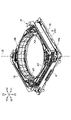
- FIGS. 12A, 12B, 13A, 13B, and 14A to 14D are views showing a configuration example of the leaf spring 6.
- FIG. 12A is a top view of the upper leaf spring 16
- FIG. 12B is a bottom view of the lower leaf spring 26.
- 13A and 13B are diagrams illustrating an example of a connection structure between the second lower leaf spring 26B and the coil 3.
- FIG. 13A is an enlarged view of the range R3 shown in FIG. 11A
- FIG. 13B shows the second lower leaf spring 26B and the coil when the portion in the range R3 shown in FIG. 11A is viewed from the Y2 side.
- FIGS. 13A and 13B for the sake of clarity, the conductive adhesive CA as a joining material is shown in a cross pattern. Further, in FIGS. 13A and 13B, a coarse dot pattern is attached to the lens holding member 2 and a fine dot pattern is attached to the coil 3 for clarification.
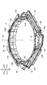
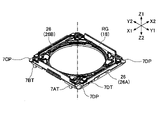
- 14A to 14D are views showing a configuration example of the base member 18 as the fixed side member RG. Specifically, FIG. 14A is an upward perspective view of the base member 18 in a state where the metal member 7 embedded in the base member 18 is removed, and FIG. 14B is an upward perspective view of the metal member 7. 14C is an upward perspective view of the base member 18 including the metal member 7, and FIG.
- FIG. 14D is an upward perspective view of the base member 18 in a state where the first lower leaf spring 26A and the second lower leaf spring 26B are attached. Is. In FIG. 14C, a dot pattern is attached to the metal member 7 for clarification. Further, in FIG. 14D, a dot pattern is attached to the lower leaf spring 26 for clarification.
- the leaf spring 6 is made of a metal plate whose main material is a copper alloy.
- the leaf spring 6 includes an upper leaf spring 16 arranged between the lens holding member 2 and the cover member 4 (strictly speaking, the spacer 1), and the lens holding member 2 and the base member 18. It includes a lower leaf spring 26 arranged between them.
- the lens holding member 2 of the leaf spring 6 is in the optical axis direction.
- the lens holding member 2 is supported so as to be movable in the (Z-axis direction).
- the lower leaf spring 26 also functions as a feeding member for supplying an electric current to the coil 3. Therefore, the first lower leaf spring 26A is electrically and mechanically connected to one end of the coil 3, and the second lower leaf spring 26B is electrically and mechanically connected to the other end of the coil 3.
- a spacer 1 is arranged between the upper leaf spring 16 and the cover member 4. The spacer 1 is arranged so as to prevent the lens holding member 2 and the cover member 4 from colliding with each other when the lens holding member 2 moves in the Z1 direction. That is, the spacer 1 is arranged so as to form a space between the lens holding member 2 and the top plate portion 4B of the cover member 4. However, the spacer 1 may be omitted as long as a space can be formed between the lens holding member 2 and the top plate portion 4B of the cover member 4 by another structure or the like.
- the upper leaf spring 16 has a substantially rectangular annular outer shape.
- the upper leaf spring 16 has an inner portion 16i as a first support portion (movable side support portion) fixed to the movable side member (lens holding member 2) and a second support portion fixed to the fixed side member RG. It includes two outer portions 16e as (fixed side supports) and four elastic arm portions 16g located between the inner portion 16i and the two outer portions 16e.
- each of the two outer portions 16e has two corner portions 16b and a crosspiece 16r connecting the two corner portions 16b.
- the crosspiece 16r is sandwiched between the spacer 1 and the magnet 5 and fixed with an adhesive.
- the spacer 1, the cover member 4, and the magnet 5 function as the fixed-side member RG.
- the inner portion 16i is placed on the pedestal portion 12d (see FIG. 6A) of the lens holding member 2 as shown in FIG. 5A. Then, the inner portion 16i is fixed to the lens holding member 2 by the adhesive AD (see FIG. 5A) applied to the recess 12dh formed in the pedestal portion 12d. As shown in FIG. 5B, the outer portion 16e is in contact with the upper surface (Z1 side surface) of the magnet 5 and is sandwiched and fixed between the spacer 1 (not shown in FIG. 5B) and the magnet 5. The outer portion 16e sandwiched and fixed between the spacer 1 and the magnet 5 functions as a fixed-side member RG.
- the upper leaf spring 16 is formed so as to be rotationally symmetric with respect to the optical axis JD.
- the upper leaf spring 16 is fixed to the lens holding member 2 at the inner portion 16i, and is fixed to the cover member 4 via the spacer 1 at the outer portion 16e. Therefore, the upper leaf spring 16 can support the lens holding member 2 in a well-balanced manner.
- first lower leaf spring 26A and the second lower leaf spring 26B are configured so that their inner shapes are substantially semicircular. Then, each of the first lower leaf spring 26A and the second lower leaf spring 26B is fixed to the inner portion 26i as the first support portion (movable side support portion) fixed to the movable side member (lens holding member 2). An outer portion 26e as a second support portion (fixed side support portion) fixed to the side member RG (base member 18) and two elastic arm portions 26g located between the inner portion 26i and the outer portion 26e. include.
- the inner portions 26i of the first lower leaf spring 26A and the second lower leaf spring 26B are the two inner joint portions 26c joined to the projecting portion 2t of the lens holding member 2.
- a connecting portion 26p connecting between the inner joining portions 26c and a connecting plate portion 26h facing the extending portion 33 of the coil 3 are included.
- each of the four projecting portions 2t of the lens holding member 2 shown in FIG. 7A has a second position shown in FIG. 12B. 1 It is inserted into a circular through hole 26r provided in the inner joint portion 26c of each of the lower leaf spring 26A and the second lower leaf spring 26B. Then, the inner joint portion 26c is fixed to the lens holding member 2 as shown in FIG. 11A by, for example, heat caulking or cold caulking the protruding portion 2t. As a result, the inner portions 26i of the first lower leaf spring 26A and the second lower leaf spring 26B are positioned and fixed to the lens holding member 2.
- the outer portion 26e of the first lower leaf spring 26A includes the outer joint portion 26d joined to the base member 18 as shown in FIG. 12B.
- the through hole 26s provided in the outer joint portion 26d of the first lower leaf spring 26A receives the projecting portion 18t (see FIG. 14A) provided on the upper surface of the base member 18. Then, the projecting portion 18t is subjected to hot caulking or cold caulking and fixed to the outer joint portion 26d.
- the outer portion 26e of the first lower leaf spring 26A is positioned and fixed to the base member 18 as shown in FIG. 14D. The same applies to the second lower leaf spring 26B.
- the first lower leaf spring 26A is connected to the lens holding member 2 via the two inner joint portions 26c, and is connected to the base member 18 via the two outer joint portions 26d.
- the second lower leaf spring 26B can support the lens holding member 2 in a state of being movable in the optical axis direction in a well-balanced manner.
- the connecting plate portion 26h of the inner portion 26i of the second lower leaf spring 26B has a jetty portion 82 of the lens holding member 2 (see FIG. 10B) when the lens driving device 101 is assembled. It is configured to face.). That is, as shown in FIG. 13A, the surface of the connection plate portion 26h on the subject side (Z1 side) faces the concave accommodating portion 82s surrounded by the jetty portion 82. Then, as shown in FIG. 13A, the facing portion 33c of the extending portion 33B of the coil 3 is an image pickup of the surface of the inner portion 26i (connecting plate portion 26h) of the second lower leaf spring 26B on the subject side and the lens holding member 2.
- the jetty portion 82 is composed of a stepped portion formed on the bottom surface of the lens holding member 2.
- the surface of the lens holding member 2 on the image sensor side (Z2 side) constitutes the inner bottom surface of the accommodating portion 82s.
- the accommodating portion 82s is configured to accommodate the conductive adhesive CA that connects the extending portion 33B of the coil 3 and the second lower leaf spring 26B.
- the jetty portion 82 is formed at a position adjacent to the protrusion 72B, the side wall of the protrusion 72B is suitably used as a part of the jetty portion 82. Therefore, the accommodating portion 82s is provided at a position adjacent to the protruding portion 72B.
- the tip of the protruding portion 72B (the end on the Z2 side) is the inner portion 26i of the second lower leaf spring 26B. It protrudes downward (in the Z2 direction) from the inner portion 26i so as to be located on the image sensor side (Z2 side) of the above. Further, a part of the winding portion 33m is also wound around the protruding portion 72B so as to be located on the image pickup element side (Z2 side) of the inner portion 26i.
- the second lower leaf spring 26B and the extending portion 33B of the coil 3 are electrically and physically connected by a conductive adhesive CA in which a conductive filler such as silver particles is dispersed in a synthetic resin.
- a conductive adhesive CA in which a conductive filler such as silver particles is dispersed in a synthetic resin.
- the conductive adhesive CA is applied to the accommodating portion 82s surrounded by the jetty portion 82 of the lens holding member 2, and then the second.
- the lower leaf spring 26B is attached to the lens holding member 2.
- the projecting portion 2t of the lens holding member 2 is heated and the conductive adhesive CA is thermally cured.
- the lens holding member 2 is typically arranged upside down so that the protruding portion 72B protrudes vertically upward. It is done in the state. Therefore, the conductive adhesive CA can be appropriately held at a desired position (position within the accommodating portion 82s) even when it has fluidity. Since a part of the facing portion 33c is arranged in the accommodating portion 82s, it is embedded in the conductive adhesive CA.
- the conductive adhesive CA is not limited to the thermosetting type, but may be an ultraviolet curable type or a moisture curable type.
- the fixed-side member RG includes a spacer 1, a cover member 4, and a magnet 5 for fixing the upper leaf spring 16, and a base member 18 for fixing each of the first lower leaf spring 26A and the second lower leaf spring 26B.
- the base member 18 is manufactured by injection molding using a synthetic resin such as a liquid crystal polymer.
- the base member 18 is a member having a rectangular plate frame-like outer shape, and a circular opening 18k is formed in the center.
- six round convex projecting portions 18t protruding upward are provided on the surface (upper surface) of the base member 18 on the subject side (Z1 side).
- the projecting portion 18t is inserted into a through hole 26s (see FIG. 12B) provided in the outer joint portion 26d of each of the first lower leaf spring 26A and the second lower leaf spring 26B. At this time, the projecting portion 18t is heat-caulked and fixed to the outer joint portion 26d.
- FIGS. 12B through hole 26s
- the projecting portion 18t is shown in a state where the tip is deformed after being heated. The same applies to the other drawings illustrating the projecting portion 18t.
- the projecting portion 18t may be cold-crimped and fixed to the outer joint portion 26d.
- a metal member 7 formed of a metal plate containing a material such as copper or iron or an alloy containing them as a main component is insert-molded and embedded in the base member 18.
- the metal member 7 includes a first metal member 7A to a fourth metal member 7D.
- each of the first metal member 7A to the fourth metal member 7D is partially exposed on the upper surface (Z1 side surface) of the base member 18.
- Each of the first metal member 7A and the second metal member 7B which are electrically insulated from each other, has a terminal portion 7AT extending downward (Z2 direction) from an end portion on the front side (X1 side) of the base member 18 and a terminal portion 7AT.
- the first metal member 7A is electrically and mechanically connected to the first lower leaf spring 26A in the exposed portion 7AP by a joining material such as solder or by welding.
- the second metal member 7B is electrically and mechanically connected to the second lower leaf spring 26B in the exposed portion 7BP by a joining material such as solder or by welding.
- the first lower leaf spring 26A is electrically and mechanically connected to one end of the coil 3
- the second lower leaf spring 26B is electrically and mechanically connected to the other end of the coil 3. Therefore, the coil 3 can receive an electric current via the first metal member 7A and the second metal member 7B and the first lower leaf spring 26A and the second lower leaf spring 26B.
- the third metal member 7C includes two connecting portions 7CP
- the fourth metal member 7D includes two connecting portions 7DP.
- the third metal member 7C exposes two connecting portions 7CP on the upper surface of the base member 18 so as to correspond to two of the lower ends of the four corners of the cover member 4.
- the fourth metal member 7D exposes two connecting portions 7DP on the upper surface of the base member 18 so as to correspond to the remaining two of the lower ends of the four corners of the cover member 4. I'm letting you.
- the inner surface of the cover member 4 near the lower end of the outer peripheral wall portion 4A is combined with and positioned on the outer peripheral side surface of the base member 18 as shown in FIG. 3A.
- the base member 18 is fixed to the cover member 4 by welding each of the connecting portion 7CP and the connecting portion 7DP and the lower ends of the four corners of the cover member 4.
- the cover member 4 and the base member 18 may be fixed at least partially with an adhesive.
- the third metal member 7C, the fourth metal member 7D, and the cover member 4 are electrically integrated and grounded via the terminal portion 7DT of the fourth metal member 7D.
- FIGS. 15A, 15B, 16A, and 16B are overall views of the lens holding member 2.
- FIG. 15A is an upward perspective view of the lens holding member 2
- FIG. 15B is a top view of the lens holding member 2.
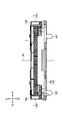
- 16A and 16B are cross-sectional views of the lens holding member 2.
- FIGS. 16A and 16B show a cross section of the lens holding member 2 in a virtual plane parallel to the YZ plane including the alternate long and short dash line L1 shown in FIG. 15B. More specifically, FIG. 16A shows a state when the cross section is viewed from diagonally above, and FIG. 16B shows a state when the cross section is viewed from the X1 side (front side).
- the inner surface SF of the tubular portion 12 is divided into upper and lower parts with a parting line PL formed in the central portion in the optical axis direction as a boundary.
- the parting line PL formed in the central portion of the inner surface SF of the tubular portion 12 is not only the parting line PL passing through the midpoint between the upper end and the lower end of the inner surface SF, but also up and down from the midpoint. It may be a parting line PL that passes through a point at a displaced position. That is, the central portion of the inner surface SF means a portion other than the upper end portion and the lower end portion of the inner surface SF.
- the parting line PL is a line corresponding to the divided surfaces (parting surfaces) of a plurality of molds used when the lens holding member 2 is injection-molded.
- the lens holding member 2 is molded using a plurality of molds including an upper mold and a lower mold (not shown), and the parting line PL is formed between the upper mold and the lower mold. Corresponds to the seam.
- the inner surface SF is divided into an upper inner surface USF and a lower inner surface LSF with the parting line PL as a boundary.
- a coarse dot pattern is attached to the upper inner surface USF and a fine dot pattern is attached to the lower inner surface LS F for clarification.
- a housing recess SR is formed in the inner surface SF of the tubular portion 12 of the lens holding member 2 shown in FIGS. 15A, 15B, 16A, and 16B.
- a cross pattern is attached to the accommodating recess SR for clarity.
- the accommodating recess SR is a recess formed so as to accommodate an adhesive (not shown) for adhering the lens body LS and the lens holding member 2 between the lens body LS and the lens holding member 2.
- 20 accommodating recesses SR are provided at equal intervals along the circumference of a circle centered on the optical axis JD.
- the contact portion CS (first) that comes into contact with the outer peripheral surface ES (see FIG. 1B) of the lens body LS.
- the contact portion CS1) is arranged.
- the accommodating recesses SR may be formed at irregular intervals along the circumference of a circle centered on the optical axis JD. Further, only one accommodating recess SR may be formed on the inner surface SF of the tubular portion 12.
- the plurality of (20 in this example) accommodating recesses SR typically have the same shape as shown in FIGS. 15A, 16A, and 16B. However, the plurality of accommodating recesses SR may include those having different shapes.
- FIGS. 15A, 16A, and 16B for the sake of clarity, only the first accommodation recess SR1 and the second accommodation recess SR2 are specified by the lead wire, and the third accommodation recess SR3 to the 20th accommodation recess SR20 are designated. The identification by the leader line is omitted.
- FIGS. 15A, 15B, 16A, and 16B for the sake of clarity, only the first contact portion CS1 is specified by the leader line for the contact portion CS, and the remaining 19 contact portions are drawn out. The line identification is omitted.
- each of the accommodating recesses SR includes an upper accommodating recess USR formed in the upper inner surface USF and a lower accommodating recess LSR formed in the lower inner surface LSF. You may.
- each of the contact portions CS may include an upper contact portion UCS formed on the upper inner surface USF and a lower contact portion LCS formed on the lower inner surface LSF.
- the first accommodating recess SR1 includes a first upper accommodating recess USR1 and a first lower accommodating recess LSR1.
- the second accommodating recess SR2 includes a second upper accommodating recess USR2 and a second lower accommodating recess LSR2.
- a first upper contact portion UCS1 is arranged between the first upper accommodating recess USR1 and the second upper accommodating recess USR2, and between the first lower accommodating recess LSR1 and the second lower accommodating recess LSR2.
- the first lower contact portion LCS1 is arranged.
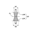
- the first upper accommodating recess USR1 extends in the vertical direction, and has a lower end portion (narrow portion) in contact with the parting line PL and an upper end portion in contact with the upper end portion of the tubular portion 12 (narrow portion). Wide part) and.
- the first lower accommodating recess LSR1 extends in the vertical direction, and has an upper end portion (narrow portion) in contact with the parting line PL and a lower end portion (wide portion) in contact with the lower end of the tubular portion 12. And have.
- the width W1 of the lower end portion of the first upper accommodating recess USR1 is smaller than the width W2 of the upper end portion of the first upper accommodating recess USR1.
- the width W3 of the upper end portion of the first lower accommodating recess LSR1 is smaller than the width W4 of the lower end portion of the first lower accommodating recess LSR1. This is because the width W1 needs to be the width W2 or less, and the width W3 also needs to be the width W4 or less so that the mold can be separated from the lens holding member 2 after injection molding.
- the width W1 and the width W3 have the same size, and the width W2 is smaller than the width W4.
- width W1 and the width W3 may have different sizes as long as the lower end portion of the first upper accommodation recess USR1 and the upper end portion of the first lower accommodation recess LSR1 are at least partially in contact with each other.
- the width W2 may be the same size as the width W4 or may be larger than the width W4.
- the first upper accommodating recess USR1 is separated by a plane whose left end portion forms an angle ⁇ 1 with respect to the XY plane, and its right end portion forms an angle ⁇ 2 with respect to the XY plane. It is formed so as to be separated by.
- the first lower accommodating recess LSR1 is partitioned by a plane whose left end forms an angle ⁇ 3 with respect to the XY plane and whose right end is separated by a plane forming an angle ⁇ 4 with respect to the XY plane. It is formed to be.
- the angle ⁇ 1 and the angle ⁇ 2 have the same magnitude
- the angle ⁇ 3 and the angle ⁇ 4 have the same magnitude.
- angle ⁇ 1 (angle ⁇ 2) is larger than the angle ⁇ 3 (angle ⁇ 4).
- angles ⁇ 1 to ⁇ 4 may all have the same size, or they may have different sizes.
- the angles ⁇ 1 to ⁇ 4 are acute angles, but they may be right angles (90 degrees) or obtuse angles.
- the 20 accommodating recesses SR are configured to have the same depth DP (see FIG. 15B), but may include those having different depths. Further, in this example, the 20 accommodating recesses SR are configured so that the depth of the upper accommodating recess USR and the depth of the lower accommodating recess LSR are the same, but the depth of the upper accommodating recess USR and the lower side. The depth of the accommodating recess LSR may be different.
- the adhesive accommodated in the accommodating recess SR can firmly bond the lens body LS and the lens holding member 2. Then, even when the adhesive cured in the accommodating recess SR (hereinafter referred to as “cured adhesive HA”) is peeled off from the lens holding member 2, the cured adhesive HA is the lens body LS. It is possible to prevent the lens holding member 2 from falling off. This is because the cured adhesive HA has the same shape as the accommodating recess SR at least in the portion near the parting line PL.
- FIG. 16A shows the first cured adhesive HA1 which is an example of the cured adhesive HA.
- the first cured adhesive HA1 in FIG. 16A is an adhesive cured in the first accommodating recess SR1 and is shown in a state of being separated from the first accommodating recess SR1 for clarification.
- the shape of the curing adhesive HA not only can limit the movement of the lens body LS with respect to the lens holding member 2 in the vertical direction, but also the lens holding member. It is also possible to limit the rotation of the lens body LS around the optical axis JD with respect to 2.
- the adhesive does not need to completely fill the accommodating recess SR, and is sufficient to suppress the movement of the lens body LS in the optical axis direction with respect to the lens holding member 2 and the rotation of the lens body LS around the optical axis JD.
- the amount may be arranged in the accommodating recess SR. That is, the cured adhesive HA does not have to have exactly the same shape as the accommodating recess SR.
- the first curing adhesive HA1 shown in FIG. 16A has a shape different from that of the first upper accommodating recess USR1 in a portion near the upper end portion of the first upper accommodating recess USR1 and has a lower end of the first lower accommodating recess LSR1.
- the portion close to the portion has a shape different from that of the first lower accommodating recess LSR1. This is because the portion of the first accommodating recess SR1 near the parting line PL is filled with the adhesive, but the entire internal space thereof is not filled with the adhesive.
- FIGS. 17A and 17B are cross-sectional views of the lens holding member 2X.
- FIG. 17A is a diagram corresponding to FIG. 16A, and shows a state when the cross section is viewed from diagonally above.
- FIG. 17B is a diagram corresponding to FIG. 16B, and shows a state when the cross section thereof is viewed from the X1 side (front side).
- the lens holding member 2X shown in FIGS. 17A and 17B is different from the lens holding member 2 having a groove portion GR on the upper inner surface USF and having an upper accommodating recess USR on the upper inner surface USF, but is different from the lens holding member 2 in other respects. Is common with. Therefore, in the following, the explanation of the common part is omitted, and the difference part is explained in detail.
- FIG. 17A a coarse dot pattern is attached to the upper inner surface USF and a fine dot pattern is attached to the lower inner surface LS F for clarification.
- FIG. 17B a cross pattern is attached to the accommodating recess SR (lower accommodating recess LSR) for clarification.
- the accommodating recess SR lower accommodating recess LSR
- FIGS. 17A and 17B for clarification, only the first lower accommodating recess LSR1 and the second lower accommodating recess LSR2 are specified by the leader line, and the other lower accommodating recess LSR is specified by the leader line. Is omitted.
- FIGS. 17A and 17B for the sake of clarity, only the first lower contact portion LCS1 is specified by the leader line for the contact portion CS, and the other lower contact portion LCS is not specified by the leader line. Has been done.
- the groove portion GR is a storage recess SR formed so as to accommodate an adhesive (not shown) for adhering the lens body LS and the lens holding member 2X between the lens body LS and the lens holding member 2X.
- the groove portion GR is a portion including a spirally formed groove.
- the groove GR is formed so as to face the smooth outer peripheral surface ES (see FIG. 1B) of the lens body LS.
- the adhesive contained in each of the accommodating recess SR (lower accommodating recess LSR) and the groove GR can firmly bond the lens body LS and the lens holding member 2X. Even when the adhesive (cured adhesive HA) cured in each of the accommodating recess SR (lower accommodating recess LSR) and the groove GR is peeled off from the lens holding member 2X, the cured adhesive HA Can prevent the lens body LS from falling off from the lens holding member 2X. This is because the cured adhesive HA in the accommodating recess SR has the same shape as the accommodating recess SR at least in a portion near the parting line PL.
- the cured adhesive HA in the groove GR is restricted from moving in the vertical direction due to the shape extending in a spiral shape, and the cured adhesive HA in the lower accommodating recess LSR has the width of the lower end. This is because the shape of the upper end is larger than the width of the upper end, which limits the upward movement. Further, the curing adhesive HA can prevent the lens body LS from rotating around the optical axis JD as in the case where only the groove portion GR is formed on the inner surface SF of the tubular portion 12. This is because the curing adhesive HA in the lower accommodating recess LSR limits the vertical movement and rotational movement of the lens body LS.
- the inner surface SF of the tubular portion 12 has a groove portion GR on the upper inner surface USF, and a substantially trapezoidal accommodating recess SR (lower accommodating recess LSR) on the lower inner surface LS F.
- the upper inner surface USF may be formed to have a substantially trapezoidal accommodating recess SR (upper accommodating recess USR)
- the lower inner surface LS F may be formed to have a groove portion GR.
- the adhesive for adhering the inner surface SF of the tubular portion 12 and the lens body LS is preferably supplied from the groove GR side, and is formed into a substantially trapezoidal accommodating recess SR through the groove GR. Be supplied.
- FIGS. 18A to 18F are views showing six configuration examples of the accommodating recess SR.
- FIG. 18A is a front view of the accommodating recess SR, and corresponds to an enlarged view of the range R4 surrounded by the alternate long and short dash line shown in FIG. 16B.
- FIGS. 18B to 18F are front views of the accommodation recess SRb to the accommodation recess SRf, and correspond to FIG. 18A.
- the accommodating recess SR and the accommodating recess SRb to the accommodating recess SRf shown in FIGS. 18A to 18F are all formed to have the same depth DP.
- the accommodating recess SR includes the upper accommodating recess USR and the lower accommodating recess LSR.
- the upper accommodating recess USR has a lower end portion in contact with the parting line PL and an upper end portion in contact with the upper surface of the tubular portion 12.
- the lower accommodating recess LSR has an upper end portion in contact with the parting line PL and a lower end portion in contact with the lower surface of the tubular portion 12.
- the upper accommodating recess USR is formed so that the width W1 of the lower end portion is smaller than the width W2 of the upper end portion
- the lower accommodating recess LSR is formed so that the width W3 of the upper end portion is smaller than the width W4 of the lower end portion. It is formed.
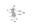
- the accommodating recess SRb includes the upper accommodating recess USRb and the lower accommodating recess LSRb.
- the accommodating recess SRb is different from the accommodating recess SR shown in FIG. 18A in that the position in the circumferential direction of the upper accommodating recess USRb on the inner surface SF of the tubular portion 12 and the position in the circumferential direction of the lower accommodating recess LSRb are deviated from each other. However, it is the same in other respects.
- the lower end of the upper accommodating recess USRb and the upper end of the lower accommodating recess LSRb have overlapping portions over the width W5.
- the lower end portion of the upper accommodating recess USRb has a non-overlapping portion having a width W6 that does not overlap with the upper end portion of the lower accommodating recess LSRb on the left side of the overlapping portion
- the upper end portion of the lower accommodating recess LSRb is upper accommodating.
- a non-overlapping portion having a width W7 that does not overlap with the lower end portion of the concave portion USRb is provided on the right side of the overlapping portion.
- the lower end of the upper accommodating recess USRb may have non-overlapping portions on both sides of the overlapping portion. That is, the upper end portion of the lower accommodating recess LSRb may overlap with a part of the lower end portion of the upper accommodating recess USRb over its entire width. Similarly, the upper end portion of the lower accommodating recess LSRb may have non-overlapping portions on both sides of the overlapping portion. That is, the lower end portion of the upper accommodating recess USRb may overlap with a part of the upper end portion of the lower accommodating recess LSRb over its entire width.
- the accommodating recess SRc includes the upper accommodating recess USRc and the lower accommodating recess LSRc.
- the accommodating recess SRc is different from the accommodating recess SR shown in FIG. 18A in that the left end and the right end of the upper accommodating recess USRc include a portion extending straight upward, but is the same in other respects.
- the upper accommodating recess USRc is formed so that the width W8 at the lower end is smaller than the width W9 at the upper end. Further, the upper accommodating recess USRc extends straight upward from the parting line PL to the position of height H1, and then extends further upward while expanding in the circumferential direction.
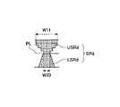
- the accommodating recess SRd includes the upper accommodating recess USRd and the lower accommodating recess LSRd.
- the accommodating recess SRd is different from the accommodating recess SR shown in FIG. 18A in that the upper accommodating recess USRd expands upward from the parting line PL in a stepped manner, but is the same in other respects.
- the upper accommodating recess USRd is formed so that the width W10 at the lower end is smaller than the width W11 at the upper end. Further, the upper accommodating recess USRd is formed so as to extend straight upward from the parting line PL and then spread straight in the circumferential direction, and repeat the upward extension and the circumferential expansion twice more. There is.
- the containment recess SRe includes an upper containment recess USRe and a lower containment recess LSRe.
- the left end of the upper accommodation recess USRe extends straight upward from the parting line PL
- the right end of the lower accommodation recess LSRe extends straight downward from the parting line PL. It differs from the accommodating recess SR shown in FIG. 18A in that it is the same in other respects.
- the upper accommodating recess USRe is formed so that the width W12 at the lower end is smaller than the width W13 at the upper end.
- the lower accommodating recess LSRe is formed so that the width W12 at the upper end portion is smaller than the width W14 at the lower end portion.
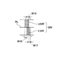
- the accommodating recess SRf includes the upper accommodating recess USRf and the lower accommodating recess LSRf.
- the accommodating recess SRf is a point where the upper accommodating recess USRf extends straight upward from the parting line PL, a point where the lower accommodating recess LSRf extends straight downward from the parting line PL, and an upper accommodating recess USRf. Is different from the accommodation recess SR shown in FIG. 18A in that the position in the circumferential direction and the position in the circumferential direction of the lower accommodating recess LSRf are different from each other, but are the same in other respects.
- the lower end of the upper accommodating recess USRf and the upper end of the lower accommodating recess LSRf have overlapping portions over the width W15.
- the lower end portion of the upper accommodating recess USRf has a non-overlapping portion having a width W16 that does not overlap with the upper end portion of the lower accommodating recess LSRf on the left side of the overlapping portion, and the upper end portion of the lower accommodating recess LSRf is upper accommodating.
- a non-overlapping portion having a width W17 that does not overlap with the lower end portion of the concave portion USRf is provided on the right side of the overlapping portion.
- the housing recesses SRb to the housing recesses SRf shown in FIGS. 18B to 18F are lenses even when the curing adhesive HA is peeled off from the lens holding member 2. It is possible to prevent the body LS from falling off from the lens holding member 2.
- the cured adhesive HA has the same shape as each of the accommodating recess SRb to the accommodating recess SRf at least in the portion near the parting line PL. That is, the cured adhesive HA in each of the upper accommodating recess USRb to the upper accommodating recess USRe is restricted from moving downward due to the shape in which the width of the upper end portion is larger than the width of the lower end portion. Further, the cured adhesive HA in each of the lower accommodating recess LSRb to the lower accommodating recess LSRe is restricted from moving upward due to the shape in which the width of the lower end portion is larger than the width of the upper end portion.
- the accommodating recess SRb there is a non-overlapping portion where the lower end portion of the upper accommodating recess USRb and the upper end portion of the lower accommodating recess LSRb do not overlap, so that the movement of the cured adhesive HA in the accommodating recess SRb in the vertical direction is restricted. Because it is done.
- the accommodating recess SRf there is a non-overlapping portion where the lower end portion of the upper accommodating recess USRf and the upper end portion of the lower accommodating recess LSRf do not overlap, so that the cured adhesive HA in the accommodating recess SRf moves in the vertical direction. This is because it is limited.
- the accommodating recess SR includes the upper accommodating recess USR and the lower accommodating recess LSR, but as in the examples shown in FIGS. 17A and 17B, the upper accommodating recess USR is a spiral groove. It may be replaced with a groove portion GR including. Further, in the accommodating recess SR, the lower accommodating recess LSR may be replaced with a groove portion GR including a spiral groove. The same applies to the examples shown in FIGS. 18B to 18F.
- FIGS. 19A to 19E are views showing four configuration examples of the accommodating recess SR.
- FIG. 19A is a front view of the accommodating recess SRh and corresponds to FIG. 18A.
- FIG. 19B shows a cross section of the lens holding member 2 (accommodation recess SRh) in the virtual plane including the alternate long and short dash line L2 shown in FIG. 19A, and is an enlarged view of the range R5 surrounded by the alternate long and short dash line shown in FIG. 16B. It corresponds.
- FIGS. 19A to 19E are cross-sectional views of the accommodating recess SRi to the accommodating recess SRk, which correspond to FIG. 19B.
- FIG. 19A all of the accommodating recesses SRh to the accommodating recesses SRk shown in FIGS. 19A to 19E are formed so as to have the same width W21 in the circumferential direction.
- the accommodating recess SRh includes an upper accommodating recess USRh and a lower accommodating recess LSRh.
- the upper accommodating recess USRh has a lower end portion in contact with the parting line PL and an upper end portion in contact with the upper surface of the tubular portion 12.
- the lower accommodating recess LSRh has an upper end portion in contact with the parting line PL and a lower end portion in contact with the lower surface of the tubular portion 12.
- the accommodating recess SRh is formed so that the widths W21 of the lower end and the upper end of the upper accommodating recess USRh and the upper end and the lower end of the lower accommodating recess LSRh are all equal.
- the upper accommodating recess USRh is formed so that the depth DP1 of the lower end portion is smaller than the depth DP2 of the upper end portion
- the lower accommodating recess LSRh is formed so that the depth DP1 of the upper end portion is the depth of the lower end portion. It is formed so as to be smaller than DP3.
- the accommodating recess SRh is formed so that the depth DP2 and the depth DP3 have the same size, but the depth DP2 and the depth DP3 have different sizes. May be.
- the accommodating recess SRi includes the upper accommodating recess USRi and the lower accommodating recess LSRi.
- the accommodation recess SRi is different from the accommodation recess SRh shown in FIG. 19B in that the depth DP4 at the lower end of the upper accommodation recess USRi and the depth DP5 at the upper end of the lower accommodation recess LSRi are different, but in other respects. It is the same.
- the depth DP4 of the lower end of the upper accommodating recess USRi is smaller than the depth DP5 of the upper end of the lower accommodating recess LSRi. Further, the depth DP4 of the lower end of the upper accommodating recess USRi is smaller than the depth DP6 of the upper end of the upper accommodating recess USRi, and the depth DP5 of the upper end of the lower accommodating recess LSRi is the lower end of the lower accommodating recess LSRi.
- the depth of the part is smaller than DP7.
- the accommodating recess SRi is formed so that the depth DP4 is smaller than the depth DP5, but the depth DP4 may be larger than the depth DP5. Further, the accommodating recess SRi is formed so that the depth DP6 is smaller than the depth DP7, but the depth DP6 may be the same as the depth DP7 or may be larger than the depth DP7.
- the accommodating recess SRj includes the upper accommodating recess USRj and the lower accommodating recess LSRj.
- the accommodating recess SRj is different from the accommodating recess SRh shown in FIG. 19B in that the depth of the upper accommodating recess USRj does not change in the vertical direction, but is the same in other respects.
- the upper accommodating recess USRj is formed so that the depth DP8 at the lower end is smaller than the depth DP9 at the upper end. Further, the upper accommodating recess USRj is formed so that the depth DP8 does not change upward from the parting line PL to the position of the height H2.
- the upper accommodating recess USRj is formed so as to be deepened with a predetermined gradient from the position of the height H2 to the upper end portion.
- the accommodating recess SRk includes the upper accommodating recess USRk and the lower accommodating recess LSRk.
- the accommodating recess SRk is different from the accommodating recess SRh shown in FIG. 19B in that the upper accommodating recess USRk becomes deeper in a stepwise manner upward from the parting line PL, but is the same in other respects.
- the upper accommodating recess USRk is formed so that the depth DP10 at the lower end is smaller than the depth DP12 at the upper end. Further, the upper accommodating recess USRk is formed so that the depth DP10 does not change upward from the parting line PL to the position of the height H3.
- the upper accommodating recess USRk has a depth DP11 at the height H3, and is formed so that the depth DP11 does not change upward from the parting line PL to the position of the height H4.
- the upper accommodating recess USRk has a depth of DP12 at a height of H4, and is formed so that the depth DP12 does not change until it reaches the upper end.
- the accommodation recess SRh to the accommodation recess SRk shown in FIGS. 19A to 19E are lenses even when the curing adhesive HA is peeled off from the lens holding member 2. It is possible to prevent the body LS from falling off from the lens holding member 2.
- the cured adhesive HA has the same shape as each of the accommodating recess SRh to the accommodating recess SRk at least in the portion near the parting line PL. That is, the cured adhesive HA in each of the upper accommodating recess USRh to the upper accommodating recess USRk is restricted from moving downward due to the shape in which the depth of the upper end portion is larger than the depth of the lower end portion. Further, the cured adhesive HA in each of the lower accommodating recess LSRh to the lower accommodating recess LSRk is restricted from moving upward due to the shape in which the depth of the lower end portion is larger than the depth of the upper end portion.
- the accommodating recess SRh includes the upper accommodating recess USRh and the lower accommodating recess LSRh, but as in the examples shown in FIGS. 17A and 17B, the upper accommodating recess USRh is a spiral. It may be replaced with a groove GR including a groove in the shape of a groove. Further, in the accommodating recess SRh, the lower accommodating recess LSRh may be replaced with a groove portion GR including a spiral groove. The same applies to the examples shown in FIGS. 19C to 19E.
- the lens driving device 101 includes a fixed side member RG including a cover member 4 as a housing HS, a lens holding member 2 arranged in the housing HS and capable of holding the lens body LS, and a lens. It is provided with a drive mechanism MK for moving the holding member 2 with respect to the fixed side member RG.
- the lens body LS is fixed to the lens holding member 2 with an adhesive.
- the lens holding member 2 has a tubular portion 12 that extends in the optical axis direction (vertical direction) and in which the lens body LS can be arranged.
- a parting line PL which is a joint of the mold when the lens holding member 2 is formed, is located at the center of the tubular portion 12 in the optical axis direction. It is formed.
- the upper inner surface USF of the tubular portion 12 on the upper side of the parting line PL and the lower inner surface LSF of the tubular portion 12 on the lower side of the parting line PL each have an accommodating recess capable of accommodating an adhesive.
- SR is formed. Then, the shape of each accommodating recess SR can regulate the relative vertical movement between the lens body LS and the lens holding member 2 by engaging with the shape of the adhesive accommodated in the accommodating recess SR. It is configured.
- a part of the cured adhesive HA accommodated in the upper accommodating recess USR has a shape in which the width of the upper end portion is larger than the width of the lower end portion, so that it engages with the upper accommodating recess USR and is downward. Movement to is restricted.
- a part of the cured adhesive HA accommodated in the lower accommodating recess LSR has a shape in which the width of the lower end portion is larger than the width of the upper end portion, it engages with the lower accommodating recess LSR and its upward movement is restricted. Will be done. The same applies to the examples shown in FIGS. 18B to 18E.
- a part of the cured adhesive HA accommodated in the upper accommodating recess USRb meshes with the upper accommodating recess USRb because the width of the lower end portion is larger than the width W5 of the overlapping portion, and moves downward. Movement is restricted. Further, since the width of the upper end portion of a part of the cured adhesive HA accommodated in the lower accommodating recess LSRb is larger than the width W5 of the overlapping portion, it meshes with the lower accommodating recess LSRb and its upward movement is restricted. .. Similarly, in the example shown in FIG.
- a part of the cured adhesive HA accommodated in the upper accommodating recess USRf meshes with the upper accommodating recess USRf because the width of the lower end portion is larger than the width W15 of the overlapping portion, and moves downward. Movement is restricted. Further, since the width of the upper end portion of a part of the cured adhesive HA accommodated in the lower accommodating recess LSRf is larger than the width W15 of the overlapping portion, it meshes with the lower accommodating recess LSRf and its upward movement is restricted. ..
- the lens holding member 2 is a case where the adhesive for adhering the lens body LS and the lens holding member 2 (curing adhesive HA accommodated in the accommodating recess SR) is peeled off from the lens holding member 2.
- the lens holding member 2 can still firmly hold the lens body LS.
- the engagement between the accommodating recess SR and the curing adhesive HA regulates the relative vertical movement between the lens body LS and the lens holding member 2, and the lens body LS (curing adhesive HA adhering to the lens body LS) is restricted. ) And the lens holding member 2 are maintained.
- At least one of the accommodating recess SR (upper accommodating recess SR) in the upper inner surface USF and the accommodating recess SR (lower accommodating recess LSR) in the lower inner surface LSF may be, for example, in the parting line PL.
- the entire cross section parallel to the parting plane at a close position may be configured to overlap the cross section parallel to the parting plane at a position far from the parting line PL in the direction perpendicular to the parting plane.
- the mold used for injection molding the lens holding member 2 is separated from the lens holding member 2 in a direction away from the parting line PL (parting surface) after injection molding. This is to be done.
- the entire cross section parallel to the parting surface at the upper end portion located near the parting line PL is the parting surface. It is configured to overlap the cross section parallel to the parting surface at the lower end portion located far from the parting line PL in the direction perpendicular to the parting line PL.
- the lower accommodating recess LSR in the lower inner surface LSF is an upper cross section (width W3, depth DP cross section) parallel to the parting surface at the upper end portion located near the parting line PL. ) are configured to overlap the lower cross section (width W4, depth DP cross section) parallel to the parting plane at the lower end located far from the parting line PL in the direction perpendicular to the parting plane.
- the entire upper cross section (width W3, cross section of depth DP) is one of the lower cross sections (width W4, cross section of depth DP) in a plan view when viewed from the Z2 side. It is configured to overlap with the part.
- FIGS. 18B to 18E the same applies to the examples shown in FIGS. 18B to 18E.
- the upper accommodating recess USRf in the upper inner surface USF is the entire cross section (width W15 + W16, cross section of depth DP) parallel to the parting surface at the lower end portion located near the parting line PL. Is configured to overlap the cross section (width W15 + W16, depth DP cross section) parallel to the parting surface at the upper end portion located far from the parting line PL in the direction perpendicular to the parting surface.
- the upper accommodating recess USRf has the entire lower cross section (width W15 + W16, cross section of depth DP) and the entire upper cross section (width W15 + W16, cross section of depth DP) in a plan view when viewed from the Z1 side. It is configured to overlap.
- the lens holding member 2 can be easily manufactured by injection molding using a plurality of molds.
- the lens holding member 2 is a case where the adhesive for adhering the lens body LS and the lens holding member 2 (curing adhesive HA accommodated in the accommodating recess SR) is peeled off from the lens holding member 2.
- the lens holding member 2 can still firmly hold the lens body LS. This is because the engagement between the accommodating recess SR and the curing adhesive HA maintains the bond between the curing adhesive HA adhering to the lens body LS and the lens holding member 2.
- the width dimension at a position far from the parting line PL is larger than the width dimension at a position close to the parting line PL. May be configured to be large.
- the depth dimension DP at a position far from the parting line PL has a depth dimension DP at a position close to the parting line PL. It may be formed to be larger than.
- the lens is held even when the adhesive (curing adhesive HA accommodated in the accommodating recess SR) that adheres the lens body LS and the lens holding member 2 is peeled off from the lens holding member 2.
- the member 2 can firmly hold the lens body LS. This is because the curing adhesive HA maintains the bond between the lens body LS and the lens holding member 2.
- the engagement between the accommodating recess SR and the cured adhesive HA causes the lens holding member 2 to be engaged.
- the adhesive does not need to completely fill the accommodating recess SR, and is sufficient to suppress the movement of the lens body LS in the optical axis direction with respect to the lens holding member 2 and the rotation of the lens body LS around the optical axis JD.
- the amount may be arranged in the accommodating recess SR.
- a plurality of the accommodating recesses SR of at least one of the above are provided so as to be spaced apart from each other in the circumferential direction of the tubular portion 12.
- 20 accommodating recesses SR are provided at intervals of angles ⁇ along the circumference of a circle centered on the optical axis JD.
- the accommodating recess SR is preferably formed on both the upper inner surface USF and the lower inner surface LS F. Then, in each of the upper accommodating recess USR in the upper inner surface USF and the lower accommodating recess LSR in the lower inner surface LSF, the entire cross section parallel to the parting surface at the position near the parting line PL is formed on the parting surface. It is configured to overlap the cross section parallel to the parting plane at a position far from the parting line PL in the vertical direction. With this configuration, the lens holding member 2 can be easily manufactured by injection molding using a plurality of molds. On top of that, the lens holding member 2 can more reliably regulate the vertical movement of the lens body LS in the optical axis direction with respect to the lens holding member 2.
- the downward movement of the lens body LS with respect to the lens holding member 2 is restricted by the engagement between a part of the cured adhesive HA accommodated in the upper accommodating recess USR and the upper accommodating recess USR, and the lens body LS is accommodated in the lower accommodating recess LSR. This is because the upward movement of the lens body LS with respect to the lens holding member 2 is restricted by the engagement between a part of the cured adhesive HA and the lower accommodating recess LSR.
- a parting line PL is sandwiched between a part of the lower end of the accommodating recess SR (upper accommodating recess USR) in the upper inner surface USF and a part of the upper end of the accommodating recess SR (lower accommodating recess LSR) in the lower inner surface LS F. It may be opposed to each other.
- the lower end of the upper accommodating recess USR may have a portion that does not face the upper end of the lower accommodating recess LSR with the parting line PL interposed therebetween.
- the upper end portion of the lower accommodating recess LSR may have a portion that does not face the lower end portion of the upper accommodating recess USR with the parting line PL interposed therebetween.
- a part of the lower end portion of the upper accommodating recess USRf and a part of the upper end portion of the lower accommodating recess LSRf face each other over the width W15 with the parting line PL interposed therebetween.
- the adhesive for adhering the lens body LS and the lens holding member 2 is supplied to the lower accommodating recess LSRf through the upper accommodating recess USRf, or is supplied to the upper accommodating recess USRf through the lower accommodating recess LSRf. Can be done.
- the lower end portion of the upper accommodating recess USRf extends over the width W16 (the upper end of the lower contact portion LCS) so as to sandwich the parting line PL and not face the upper end portion of the lower accommodating recess LSRf. It has a part facing the part).
- the upper end portion of the lower accommodating recess LSRf has a portion (a portion facing the lower end portion of the upper contact portion UCS) having a width W17 that does not face the lower end portion of the upper accommodating recess USRf with the parting line PL interposed therebetween.
- the lens holding member 2 can still firmly hold the lens body LS. This is because the coupling between the lens body LS and the lens holding member 2 is maintained by the engagement between the cured adhesive HA and the accommodating recess SR (contact portion CS).
- the accommodation recess SR (accommodation recess SRf) is a portion where only the lower end portion of the upper accommodation recess USRf does not face the upper end portion of the lower accommodation recess LSRf with the parting line PL interposed therebetween (the upper end portion of the lower contact portion LCS). It may be configured to have a portion facing the surface). That is, the accommodating recess SR may be formed so that the upper end portion of the lower accommodating recess LSRf faces the lower end portion of the upper accommodating recess USRf over its entire width.
- the accommodation recess SR only the upper end portion of the lower accommodation recess LSRf sandwiches the parting line PL and does not face the lower end portion of the upper accommodation recess USRf (the portion facing the lower end portion of the upper contact portion UCS). It may be configured to have. That is, the accommodating recess SR may be formed so that the lower end portion of the upper accommodating recess USRf faces the upper end portion of the lower accommodating recess LSRf over its entire width.
- the lower end of the upper accommodating recess USRf and the upper end of the lower accommodating recess LSRf may be configured not to face each other with the parting line PL interposed therebetween. That is, in the accommodation recess SR, the lower end of the upper accommodation recess USRf faces the upper end of the lower contact portion LCS over the entire width, and the upper end of the lower accommodation recess LSRf faces the upper end of the upper contact portion UCS over the entire width. It may be formed so as to face the portion.
- the accommodating recess SR formed on one of the upper inner surface USF and the lower inner surface LSF has a party in which the entire cross section parallel to the parting surface at a position close to the parting line PL is perpendicular to the parting surface.
- the accommodating recess SR formed on the other side of the upper inner surface USF and the lower inner surface LSF is configured to overlap the cross section parallel to the parting surface at a position far from the parting line PL, and is configured by a spiral groove. You may. Since the spiral groove is machined by pulling out the spiral groove while rotating the mold in which the spiral uneven portion is formed, it is easier to machine than the form in which a plurality of annular grooves are formed in parallel. Is.
- a groove portion GR including a spiral groove may be formed on the upper inner surface USF, and a storage recess SR (lower storage recess LSR) may be formed on the lower inner surface LSF. ..
- the adhesive is supplied from above to the groove GR in a state where the lens body LS is arranged inside the tubular portion 12 of the lens holding member 2, and reaches the lower accommodating recess LSR through the groove GR. Therefore, in this configuration, the adhesive is easily supplied from above.
- the accommodating recess SR may be configured to increase as the width dimension increases away from the parting line PL. In this configuration, the opening of the accommodating recess SR when viewed from directly above or directly below is large, so that the adhesive can be easily supplied.
- the first lower leaf spring 26A and the extending portion 33A are electrically and mechanically connected, and the second lower leaf spring 26B and the extending portion 33B are connected to each other. Is electrically and mechanically connected, but the present invention is not limited to this configuration.
- the upper leaf spring 16 is divided into two, one of which is electrically and mechanically connected to the extending portion 33A, and the other is extended. It may include a configuration that is electrically and mechanically connected to the existing portion 33B.
- the upper leaf spring 16 is arranged so as to connect the magnet holder as the support member and the lens holding member 2, and is configured to support the lens holding member 2 so as to be movable in the optical axis direction. ..
- the upper leaf spring 16 has an inner portion 16i as a first support portion fixed to the lens holding member 2, an outer portion 16e as a second support portion fixed to the magnet holder, and an inner portion 16i and an outer side. Includes an elastic arm portion 16g located between the portion 16e.
- the magnet holder is a member that holds the magnet 5 facing the coil 3 held by the lens holding member 2, and is typically connected to the base member 18 via a suspension wire in the optical axis direction by the suspension wire.
- the magnet holder is perpendicular to the optical axis direction by a drive mechanism composed of a magnet 5 and a coil different from the coil 3 installed on the base member 18 so as to face the magnet 5. It is configured to be able to move in a direction.
- a flange portion having a notch may be provided on the upper end side (Z1 side) of the lens holding member 2.
- the projecting portion 72 is provided so as to project upward from the upper end portion which is one end portion in the optical axis direction of the lens holding member 2 on the side where the upper leaf spring 16 is arranged.
- the magnet holder functions as a fixed-side member that does not move in the optical axis direction with respect to the lens holding member that moves in the optical axis direction.
- the coil 3 is wound in an octagonal ring on the outer peripheral surface side of the lens holding member 2.
- the coil 3 has an oval or oval coil body portion held on the side surface of the lens holding member 2, that is, a coil body portion arranged so that the central axis is perpendicular to the optical axis direction. It may be a coil.
- the coil 3 has four oval-shaped coil main bodies held on each of the four side surfaces of the lens holding member 2 provided with the coil support portion 12j having a substantially rectangular outer shape when viewed from above. It may be a coil, or it may be a coil having two oval-shaped coil main bodies held on each of the two facing surfaces of the lens holding member 2.
- the first magnet 5A may be a combination of two two-pole magnets or one quadrupole magnet. The same applies to the second magnet 5B.
- the magnet 5 is arranged so as to face two of the four side portions of the lens holding member 2, it may be arranged so as to face each of the four side portions, and the four magnets 5 may be arranged so as to face each of the four side portions. It may be arranged so as to face each of the square wall portions.
- the drive mechanism MK is configured to utilize the coil 3 provided in the lens holding member 2 and the magnet 5 arranged so as to face the coil 3, but is piezoelectric.
- Other drive methods such as the method may be used.
- the cover member 4 may be made of a magnetic metal.
- 2nd metal member 7BP ... ⁇ ⁇ Exposed part 7BT ⁇ ⁇ ⁇ Terminal part 7C ⁇ ⁇ ⁇ 3rd metal member 7CP ⁇ ⁇ ⁇ Connection part 7D ⁇ ⁇ ⁇ 4th metal member 7DP ⁇ ⁇ ⁇ Connection part 7DT ⁇ ⁇ ⁇ Terminal part 12 ⁇ ⁇ ⁇ Cylindrical Part 12d ... Pedestal part 12dh ... Recess 12h ... Eaves part 12j ... Coil support part 13 ... Winding part 16 ... Upper leaf spring 16b ... Corner part 16e ...
- Connection plate part 26i ... ⁇ Inner part 26p ⁇ ⁇ ⁇ Connecting part 26r ⁇ ⁇ ⁇ Through hole 26s ⁇ ⁇ ⁇ Through hole 33, 33A, 33B ⁇ ⁇ ⁇ Extension part 33c ⁇ ⁇ ⁇ Opposing part 33k ⁇ ⁇ ⁇ Insertion part 33m ⁇ ⁇ ⁇ Winding part 52 ... Flange part 52k ... Notch part 72, 72A, 72B ... Protruding part 82 ... Jetty part 82s ... Accommodating part 101 ... Lens drive device AD ...
- Adhesive CA Conductive adhesive CS ⁇ ⁇ ⁇ Contact part ES ⁇ ⁇ ⁇ Outer surface GR ⁇ ⁇ ⁇ Groove part HA ⁇ ⁇ ⁇ Curing adhesive HA1 ⁇ ⁇ ⁇ First curing adhesive HS ⁇ ⁇ ⁇ Housing JD ⁇ ⁇ ⁇ Optical axis LCS ⁇ ⁇ ⁇ Lower contact part LS ⁇ ⁇ ⁇ Lens body LSF ⁇ ⁇ ⁇ Lower inner surface LSR, LSRb ⁇ LSRf, LSRh ⁇ LSRk ⁇ ⁇ ⁇ Lower accommodation recess MK ⁇ ⁇ ⁇ Drive mechanism PL ⁇ ⁇ ⁇ Parting line RG ... Fixed side member SF ...
- Inner surface SR, SRb-SRf, SRh-SRk Storage recess UCS ... Upper contact part USF ... Upper inner surface USR, USRb-USRf, USRh-USRk ... ⁇ Upper storage recess
Landscapes
- Physics & Mathematics (AREA)
- General Physics & Mathematics (AREA)
- Optics & Photonics (AREA)
- Lens Barrels (AREA)
Priority Applications (2)
| Application Number | Priority Date | Filing Date | Title |
|---|---|---|---|
| CN202180084699.2A CN116601565B (zh) | 2020-12-17 | 2021-12-09 | 透镜驱动装置及摄像机模组 |
| JP2022569923A JP7434608B2 (ja) | 2020-12-17 | 2021-12-09 | レンズ駆動装置及びカメラモジュール |
Applications Claiming Priority (2)
| Application Number | Priority Date | Filing Date | Title |
|---|---|---|---|
| JP2020209648 | 2020-12-17 | ||
| JP2020-209648 | 2020-12-17 |
Publications (1)
| Publication Number | Publication Date |
|---|---|
| WO2022131119A1 true WO2022131119A1 (ja) | 2022-06-23 |
Family
ID=82059133
Family Applications (1)
| Application Number | Title | Priority Date | Filing Date |
|---|---|---|---|
| PCT/JP2021/045301 Ceased WO2022131119A1 (ja) | 2020-12-17 | 2021-12-09 | レンズ駆動装置及びカメラモジュール |
Country Status (3)
| Country | Link |
|---|---|
| JP (1) | JP7434608B2 (https=) |
| CN (1) | CN116601565B (https=) |
| WO (1) | WO2022131119A1 (https=) |
Citations (6)
| Publication number | Priority date | Publication date | Assignee | Title |
|---|---|---|---|---|
| JPH11211957A (ja) * | 1998-01-23 | 1999-08-06 | Nikon Corp | レンズ保持部材 |
| JP2005227500A (ja) * | 2004-02-12 | 2005-08-25 | Fujinon Corp | 撮像装置 |
| JP2009128680A (ja) * | 2007-11-26 | 2009-06-11 | Olympus Corp | 鏡枠及びレンズユニット |
| WO2010116687A1 (ja) * | 2009-04-06 | 2010-10-14 | パナソニック株式会社 | レンズユニット |
| JP2014112121A (ja) * | 2012-12-05 | 2014-06-19 | Konica Minolta Inc | レンズ鏡胴及び像取得ユニット |
| JP2019008201A (ja) * | 2017-06-27 | 2019-01-17 | 日本電産サンキョー株式会社 | レンズユニットおよびレンズユニットの製造方法 |
-
2021
- 2021-12-09 CN CN202180084699.2A patent/CN116601565B/zh active Active
- 2021-12-09 JP JP2022569923A patent/JP7434608B2/ja active Active
- 2021-12-09 WO PCT/JP2021/045301 patent/WO2022131119A1/ja not_active Ceased
Patent Citations (6)
| Publication number | Priority date | Publication date | Assignee | Title |
|---|---|---|---|---|
| JPH11211957A (ja) * | 1998-01-23 | 1999-08-06 | Nikon Corp | レンズ保持部材 |
| JP2005227500A (ja) * | 2004-02-12 | 2005-08-25 | Fujinon Corp | 撮像装置 |
| JP2009128680A (ja) * | 2007-11-26 | 2009-06-11 | Olympus Corp | 鏡枠及びレンズユニット |
| WO2010116687A1 (ja) * | 2009-04-06 | 2010-10-14 | パナソニック株式会社 | レンズユニット |
| JP2014112121A (ja) * | 2012-12-05 | 2014-06-19 | Konica Minolta Inc | レンズ鏡胴及び像取得ユニット |
| JP2019008201A (ja) * | 2017-06-27 | 2019-01-17 | 日本電産サンキョー株式会社 | レンズユニットおよびレンズユニットの製造方法 |
Also Published As
| Publication number | Publication date |
|---|---|
| CN116601565B (zh) | 2025-10-10 |
| CN116601565A (zh) | 2023-08-15 |
| JPWO2022131119A1 (https=) | 2022-06-23 |
| JP7434608B2 (ja) | 2024-02-20 |
Similar Documents
| Publication | Publication Date | Title |
|---|---|---|
| US10739550B2 (en) | Voice coil motor | |
| JP6392698B2 (ja) | レンズ駆動装置 | |
| JPWO2016175210A1 (ja) | レンズ駆動装置 | |
| JP6793065B2 (ja) | レンズ駆動装置、前記レンズ駆動装置を使用したカメラモジュールおよびレンズ駆動装置の製造方法 | |
| WO2022131119A1 (ja) | レンズ駆動装置及びカメラモジュール | |
| JP7253050B2 (ja) | レンズ駆動装置及びカメラモジュール | |
| CN212989746U (zh) | 透镜驱动装置以及相机模块 | |
| JP2020154254A (ja) | レンズ駆動装置、カメラモジュール、及び、レンズ駆動装置の製造方法 | |
| JP7441759B2 (ja) | レンズ駆動装置及びカメラモジュール | |
| JP7323622B2 (ja) | レンズ駆動装置及びカメラモジュール | |
| JP6826212B2 (ja) | レンズ駆動装置、カメラモジュール、及び、レンズ駆動装置の製造方法 | |
| JP7394229B2 (ja) | レンズ駆動装置及びカメラモジュール | |
| JP2023132242A (ja) | レンズ駆動装置及びカメラモジュール | |
| JP2793786B2 (ja) | 光ディスク装置の対物レンズ駆動装置とその製造方法 | |
| JP2021096337A (ja) | レンズ駆動装置及びカメラモジュール | |
| JP7525335B2 (ja) | レンズ駆動装置及びカメラモジュール | |
| JP7304946B2 (ja) | レンズ駆動装置、カメラモジュール、及びレンズ駆動装置の製造方法 | |
| WO2019181350A1 (ja) | レンズ駆動装置及びカメラモジュール | |
| JP2025012143A (ja) | レンズ駆動装置及びカメラモジュール | |
| JP2022187410A (ja) | レンズ駆動装置及びカメラモジュール | |
| JPWO2020100601A1 (ja) | レンズ駆動装置及びカメラモジュール | |
| JP2021128192A (ja) | レンズ駆動装置、カメラモジュール、及びレンズ駆動装置の製造方法 | |
| WO2019181352A1 (ja) | レンズ駆動装置及びカメラモジュール | |
| JPH08321056A (ja) | 光ピックアップ装置 | |
| JP2006107563A (ja) | 光ピックアップ装置の製造方法 |
Legal Events
| Date | Code | Title | Description |
|---|---|---|---|
| 121 | Ep: the epo has been informed by wipo that ep was designated in this application |
Ref document number: 21906482 Country of ref document: EP Kind code of ref document: A1 |
|
| ENP | Entry into the national phase |
Ref document number: 2022569923 Country of ref document: JP Kind code of ref document: A |
|
| WWE | Wipo information: entry into national phase |
Ref document number: 202180084699.2 Country of ref document: CN |
|
| NENP | Non-entry into the national phase |
Ref country code: DE |
|
| 122 | Ep: pct application non-entry in european phase |
Ref document number: 21906482 Country of ref document: EP Kind code of ref document: A1 |
|
| WWG | Wipo information: grant in national office |
Ref document number: 202180084699.2 Country of ref document: CN |