WO2022130700A1 - 電子制御装置 - Google Patents
電子制御装置 Download PDFInfo
- Publication number
- WO2022130700A1 WO2022130700A1 PCT/JP2021/031850 JP2021031850W WO2022130700A1 WO 2022130700 A1 WO2022130700 A1 WO 2022130700A1 JP 2021031850 W JP2021031850 W JP 2021031850W WO 2022130700 A1 WO2022130700 A1 WO 2022130700A1
- Authority
- WO
- WIPO (PCT)
- Prior art keywords
- data
- data block
- block
- update
- updated
- Prior art date
- Legal status (The legal status is an assumption and is not a legal conclusion. Google has not performed a legal analysis and makes no representation as to the accuracy of the status listed.)
- Ceased
Links
Images



Classifications
-
- G—PHYSICS
- G06—COMPUTING OR CALCULATING; COUNTING
- G06F—ELECTRIC DIGITAL DATA PROCESSING
- G06F8/00—Arrangements for software engineering
- G06F8/60—Software deployment
- G06F8/65—Updates
-
- B—PERFORMING OPERATIONS; TRANSPORTING
- B60—VEHICLES IN GENERAL
- B60R—VEHICLES, VEHICLE FITTINGS, OR VEHICLE PARTS, NOT OTHERWISE PROVIDED FOR
- B60R16/00—Electric or fluid circuits specially adapted for vehicles and not otherwise provided for; Arrangement of elements of electric or fluid circuits specially adapted for vehicles and not otherwise provided for
- B60R16/02—Electric or fluid circuits specially adapted for vehicles and not otherwise provided for; Arrangement of elements of electric or fluid circuits specially adapted for vehicles and not otherwise provided for electric constitutive elements
-
- H—ELECTRICITY
- H04—ELECTRIC COMMUNICATION TECHNIQUE
- H04L—TRANSMISSION OF DIGITAL INFORMATION, e.g. TELEGRAPHIC COMMUNICATION
- H04L63/00—Network architectures or network communication protocols for network security
- H04L63/04—Network architectures or network communication protocols for network security for providing a confidential data exchange among entities communicating through data packet networks
- H04L63/0428—Network architectures or network communication protocols for network security for providing a confidential data exchange among entities communicating through data packet networks wherein the data content is protected, e.g. by encrypting or encapsulating the payload
Definitions
- the present invention relates to an electronic control device mounted on a vehicle.
- An in-vehicle electronic control device such as an ECU (Electrical Control Unit) is controlled by a microcomputer (hereinafter referred to as a microcomputer).
- a microcomputer hereinafter referred to as a microcomputer.
- the ECU controls the target device by executing the control software stored in the flash ROM (Read Only Memory) which is a non-volatile memory.
- flash ROM Read Only Memory
- the ECU generally has a means for rewriting the control software written in the memory mounted on the ECU.
- a means for rewriting the control software written in the memory mounted on the ECU For example, there are the following means: (1) Connect a diagnostic tool to the ECU by wire via an OBD (On-Board Diagnostics) connector, and transmit data to be written to the flash ROM by a signal such as CAN (Control Area Network). Method (conventional method); (2) OTA (Over-The-Air): A method of transmitting updated data to the ECU by wireless communication.
- updated data may be received while the vehicle is running.
- the software rewriting time becomes long, and the process may be interrupted due to factors such as the power supply being cut off by the user. In such a case, there is a demand for a resume function that starts from the middle even if software rewriting is interrupted.
- Patent Document 1 describes the resume function of software rewriting.
- the data transfer source requests the ECU for the software rewriting start address.
- Patent Document 1 needs to hold the position of the data block requesting retransmission on the ECU side. Therefore, it is considered that the address in the ROM data held by the ECU and the address in the ROM data transmitted from the server or the like are assumed to be the same.
- the ROM data to be transmitted may be compressed, encrypted, or both.
- ROM data compression has the advantage of contributing to shortening the communication time in software rewriting
- encryption has the advantage of contributing to enhanced security.
- it may be difficult to identify relative or absolute addresses when compared to raw ROM data that has not been compressed or encrypted.
- the present invention has been made in view of the above problems, and provides a technique capable of appropriately specifying the retransmission start address even when the update data is compressed or encrypted. With the goal.
- the updated data includes at least one of compressed data and encrypted data, and includes unprocessed data that is neither compressed nor encrypted, and the unprocessed data is the updated data. It holds an address list that can identify the location of each data block contained within.
- the retransmission start address can be appropriately specified.
- FIG. 1 It is a block diagram of the electronic control unit (ECU) 1 which concerns on Embodiment 1.
- FIG. It is a schematic diagram which shows the state which the update data 3 is encrypted. It is a block diagram of the global header 31. It is a flowchart explaining the resume process in program update. It is a flowchart explaining the process which the update data transmission unit 2 transmits the update data 4. It is a flowchart explaining the detail of S408. It is a flowchart explaining the detail of S603.
- FIG. It is a block diagram of the ECU 1 which concerns on Embodiment 3.
- FIG. It is a block diagram of the ECU 1 which concerns on Embodiment 4.
- FIG. 1 is a block diagram of an electronic control unit (ECU) 1 according to the first embodiment of the present invention.
- the ECU 1 is mounted on the vehicle.
- the ECU 1 controls the equipment mounted on the vehicle. Examples of in-vehicle devices include engines, power steering devices, control brake devices, and the like.
- the ECU 1 controls these devices by executing a control program that implements a process for controlling the in-vehicle devices.
- the ECU 1 includes a microcomputer 11.
- the microcomputer 11 has at least one CPU (Central Processing Unit) 12 for executing software, at least one volatile RAM (Random Access Memory) 13, at least one non-volatile memory 15 for holding programs and data, and at least one communication.
- a unit 14 is provided.
- the communication unit 14 is connected to an update data transmission unit 2 outside the ECU 1, and receives update data via the update data transmission unit 2 when updating a program.
- the update data transmission unit 2 may be, for example, a terminal for program update that is preferentially connected to the data communication connector of the vehicle, or may be a server computer that communicates with the ECU 1 by wireless communication. Alternatively, it may be another ECU mounted on the same vehicle.
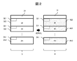
- FIG. 2 is a schematic diagram showing how the update data 3 is encrypted.
- the update data 3 is data including an updated version such as a program executed by the ECU 1.
- the update data 3 is transmitted to the ECU 1 by wireless communication from, for example, a data center.
- the update data 3 is configured as, for example, binary data itself stored in the non-volatile memory 15.
- the update data 3 is composed of a global header 31 and one or more data blocks (data blocks 32, 33, and 3N are exemplified in FIG. 2).
- the data block is composed of a local header part and a body part (for example, the data block 32 is composed of a local header 321 and a body 322).
- the size of each data block may be the same or different.
- the body part of the data block is compressed before being transmitted to the ECU 1.
- the local header part is not compressed.
- a local header is added to the compressed body part.
- Update data 3 is created by concatenating a pair of a local header and a body to form one data, and further adding a global header 31.
- the local header describes the incidental information of the data block, and the global header describes the incidental information of the entire update data 3. Details of these headers will be described later.
- the update data 3 is encrypted before being transmitted to the ECU 1 to become the update data 4.
- the update data 4 has an encrypted data block (data blocks 42, 43, 4N are exemplified in FIG. 2).
- the global header 31 is added as it is without being encrypted.
- the encryption algorithm the block cipher is used in this embodiment, but another algorithm may be used. When the block cipher algorithm is used, the update data 4 is encrypted for each data block and then for each block of a certain size.
- the local header may or may not be encrypted. That is, as will be described later, it suffices if the correspondence between each data block in the update data 4 and the storage address of each data block on the non-volatile memory 15 can be specified. In other words, this correspondence may be described in the global header 31 or in each local header. In the former case, by describing the start address of each data block in the update data 4 in the global header 31, the ECU 1 is between each data block in the update data 4 and the storage destination address in the non-volatile memory 15. Since the correspondence between the two can be specified, each local header may be encrypted. In the latter case, each local header describes the position of the next local header in the update data 4, and by continuing this, the position of each data block in the update data 4 is specified.
- the local header of the data block describes information that can specify the position (address) in which the data block should be stored in the non-volatile memory 15.
- the ECU 1 can specify the correspondence relationship between each data block in the update data 4 and the storage destination address in the non-volatile memory 15.
- the global header 31 is not encrypted.
- the local header does not necessarily have to be placed at the beginning of the data block, for example, it may be placed at the end of the data block, or it may be placed at an arbitrary position between the beginning and the end.
- the head of the body of the next data block may be specified, or the local header of the next data block (however, the local header is placed at the head of the data block). (Only when it is) may be specified.
- FIG. 3 is a configuration diagram of the global header 31.
- the global header 31 has ROM information 311 and a resume address 312 and an IV (Initial Vector) 313.
- IV Initial Vector
- FIG. 3 an example is shown in which the relationship between the data block and the storage destination address in the non-volatile memory 15 (that is, the resume address 312) is stored in the global header 31.
- the ROM information 311 is information such as the number of blocks constituting the update data 3, the size of the update data 3, and the code indicating the compression / encryption algorithm.
- the resume address 312 describes the correspondence between the start address of each data block in the update data 3 and the address in which the data block is written in the non-volatile memory 15. The address itself in the non-volatile memory 15 may be described, or other information that can specify the address in the non-volatile memory 15 may be described.
- IV313 is the information required to decrypt the first encrypted data block (data block 42 in FIG. 2) in the block cipher.
- the ROM information 311 and the resume address 312 may be included in the local header.
- the IV 313 may not be included in the global header 31 and may be stored in the non-volatile memory 15 in advance.
- a part or all of each information in the global header 31 is transmitted to the ECU 1 via the update data transmission unit 2 and then stored in the non-volatile memory 15.
- the resume address 312 is stored in the non-volatile memory 15, and other information in the global header 31 is not stored.
- IV313 may be stored in the non-volatile memory 15.
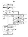
- FIG. 4 is a flowchart illustrating the resume process in the program update. Each step of FIG. 4 will be described below.
- the update data transmission unit 2 requests the ECU 1 to transmit the transfer start address of the update data 4.
- the transfer start address is, for example, an address that specifies from which of the update data 4 the update data 4 is retransmitted to the ECU 1 when the process of writing the update data 4 to the non-volatile memory 15 is interrupted. If it is not interrupted, the start address may be specified.
- Step S402 The CPU 12 determines whether or not the data block first written to the non-volatile memory 15 is the first data block of the update data 4. This determination can be performed by referring to the write completion block information described later. If the first data block is to be written from now on, the process proceeds to S403, and if a data block other than the first data block is to be written from now on, the process proceeds to S404.
- Steps S403 and S407 The CPU 12 sets the transfer start request address at the beginning of the update data 4 (S403). The CPU 12 returns the transfer start request address to the update data transmission unit 2 (S407).
- Steps S404 to S406, S407 The CPU 12 specifies the start address of the area in which the data block in the non-volatile memory 15 has not been written according to the write completion block information (S404).
- the CPU 12 specifies the corresponding address in the update data 4 according to the specified address (S405). This address becomes the resume address of the update data 4.
- the correspondence between the address in the non-volatile memory 15 and the address in the update data 4 may be stored in the non-volatile memory 15 in advance, for example.
- this correspondence relationship is held in advance in the update data transmission unit 2, and the CPU 12 designates the address in the non-volatile memory 15 as the resume address, and the update data transmission unit 2 specifies the correspondence in the update data 4 according to the correspondence relationship. You may specify the address to be used.
- the CPU 12 sets the resume address as the transfer start request address (S406).
- the CPU 12 returns the transfer start request address to the update data transmission unit 2 (S407).
- the position of the data block in the update data 4 may be specified by the address in the update data 4, or may be specified by information other than the address such as the number of the data block. That is, it suffices that at least the information that can specify the correspondence between the data block in the update data 4 and the position in the non-volatile memory 15 can be shared between the update data transmission unit 2 and the ECU 1.
- Step S408 When the update data transmission unit 2 receives the transfer start request address from the ECU 1, the update data transmission unit 2 transmits the portion of the update data 4 after the transfer start request address to the ECU 1.
- the CPU 12 receives the update data 4 and writes it to the non-volatile memory 15. Details of this step will be described later.
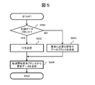
- FIG. 5 is a flowchart illustrating a process in which the update data transmission unit 2 transmits the update data 4.
- the update data transmission unit 2 receives the transfer start request address from the ECU 1, the update data transmission unit 2 starts this flowchart.
- Each step of FIG. 5 will be described below.
- Step S501 The update data transmission unit 2 determines whether or not the transfer start request address is the first encrypted data block of the update data 4. If it is the beginning, the process proceeds to S502, and if it is not the beginning, the process proceeds to S503.
- step S502 The update data transmission unit 2 transmits IV313 used for decrypting the encrypted data block at the beginning of the update data 4 to the ECU 1.
- the update data transmission unit 2 transmits another encrypted data block used for decrypting the data block of the update data 4 to the ECU 1.
- the encryption is performed using the encrypted data block immediately before the data block. Therefore, the update data transmission unit 2 transmits the encrypted data block immediately before the data block specified by the transfer start request address to the ECU 1.
- the update data transmission unit 2 sequentially transmits data to the ECU 1 from the data block designated by the transfer start request address.
- the ECU 1 can perform decoding of the data block received first by using the data block received in S502 or S503.
- the previously received data block can be temporarily stored in a RAM 13 or the like, and decoding can be performed using this.
- the data block used for decoding may be temporarily stored in RAM 13 or the like.
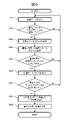
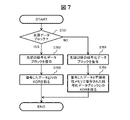
- FIG. 6 is a flowchart illustrating the details of S408. Each step of FIG. 6 will be described below.
- the communication unit 14 receives the update data 4 from the update data transmission unit 2.
- the CPU 12 stores the global header 31 (ROM information 311, resume address 312, IV313) included in the update data 4 in the RAM 13 or the non-volatile memory 15.
- Step S602 The CPU 12 determines whether or not one or more encrypted data blocks have been received. For example, this determination can be performed based on whether or not the data received from the update data transmission unit 2 has reached the size of the encrypted data block. If one or more encrypted data blocks are received, the process proceeds to S603, and if not received, the process returns to S601 to continue receiving data.
- Step S603 The CPU 12 decrypts the received encrypted data block.
- the decoded data is expanded in the RAM 13 or the non-volatile memory 15. The details of the decoding process in this step will be described later.
- Step S604 The CPU 12 stores the last decrypted encrypted data block in the RAM 13 or the non-volatile memory 15 for use in decrypting the next encrypted data block.
- Step S605 The CPU 12 determines whether or not one or more compressed data blocks are included in the decoded data. For example, if the decoded data size is less than one compressed data block, it can be determined that there is no compressed data block. If the compressed data block is not included, it returns to S601 and continues to receive data. If the compressed data block is included, the process proceeds to S606.
- Step S606 The CPU 12 decompresses the compressed data block.
- Step S607 The CPU 12 determines whether or not the decompressed data has reached the write block size of the non-volatile memory 15. If it has not been reached, the process returns to step S601 to continue receiving data. If it has reached, proceed to S608.
- Steps S608 to S609 The CPU 12 writes the decompressed data to the non-volatile memory 15 (S608).
- the CPU 12 stores the write completion data block information indicating that the data block has been written in the non-volatile memory 15 (S609).
- the write completion data block information can also be used for checking the consistency of the written data block.
- the CPU 12 may determine whether or not the data block has been normally written by performing error correction processing or the like using the write completion data block information.
- FIG. 7 is a flowchart illustrating the details of S603.
- the encryption process and the decryption process use the AES-CBC (Advanced Encryption Standard-Cipher Block Chaining) mode, but the encryption process and the decryption process are not limited to this, and another algorithm may be used. Each step of FIG. 7 will be described below.
- AES-CBC Advanced Encryption Standard-Cipher Block Chaining
- Step S701 The CPU 12 determines whether or not the data block to be decrypted is the first encrypted data block (data block 42 in the example of FIG. 2) in the update data 4. If the first encrypted data block is to be decrypted from now on, the process proceeds to S702, and if the second and subsequent encrypted data blocks are to be decrypted from now on, the process proceeds to S704.
- Step S702 The CPU 12 decrypts the first encrypted data block in the update data 4.
- the decryption key for example, the same one used in the encryption process for generating the encrypted data block is used.
- the decryption key may be stored in the non-volatile memory 15 in advance, or may be transmitted to the ECU 1 by another secure method.
- Step S703 The CPU 12 generates a plaintext block, so-called plain text, by taking an exclusive OR (XOR) between the decrypted encrypted data block and the IV313 stored in the non-volatile memory 15 in S408 of FIG. Can be done.
- S702 to S703 may be collectively regarded as a decoding process in a broad sense. The same applies to S704 and S705.
- Step S704 The CPU 12 decrypts the second and subsequent encrypted data blocks in the update data 4.
- the decryption key is the same as S702.
- Step S705 The CPU 12 can generate a plaintext block by XORing the decrypted encrypted data block and the encrypted data block stored in the non-volatile memory 15 in S604 of FIG.
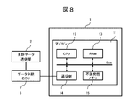
- FIG. 8 is a configuration diagram of the ECU 1 according to the second embodiment of the present invention.
- the data relay ECU 5 may relay the update data 4.
- the data relay ECU 5 is a gateway device arranged between the ECU 1 and the update data transmission unit 2, and can be mounted in the same in-vehicle network as the ECU 1.
- the data relay ECU 5 temporarily saves a copy thereof.
- the data relay ECU 5 does not decode or decompress the updated data 4.
- the update data transmission unit 2 in the first embodiment can be replaced with the data relay ECU 5, and the resume can be realized by the same method as the first embodiment.
- the update data 4 may be retransmitted between the update data transmission unit 2 and the data relay ECU 5. Since the data relay ECU 5 does not decode or decompress the update data 4, the retransmission start address may be simply immediately after the address range saved in the data relay ECU 5.
- FIG. 9 is a block diagram of the ECU 1 according to the third embodiment of the present invention.
- the update data 4 may be stored in a non-volatile storage device such as a flash memory 17 arranged outside the microcomputer 11 instead of the non-volatile memory 15.
- the microcomputer 11 accesses the flash memory 17 via an interface such as the serial communication unit 16 and writes the data block obtained by decoding / decompressing the update data 4.
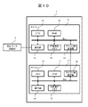
- FIG. 10 is a block diagram of the ECU 1 according to the fourth embodiment of the present invention.
- the present invention can be applied even when the ECU 1 includes two or more microcomputers 11 as shown in FIG. Specifically, one of the microcomputers 11 receives the update data 4.
- the data block obtained by decompression / decoding from the update data 4 is shared by the other microcomputers 11 via the inter-microcomputer communication unit 18.
- the ECU 1 is an electronic control device mounted on a vehicle, and is an arithmetic unit that executes a program that implements a process for controlling the equipment mounted on the vehicle, and updates the program.
- a communication unit for receiving update data used for the purpose and a storage unit for storing the program are provided, and the update data is at least one of compressed data subjected to compression processing and encryption data subjected to encryption processing. Including unprocessed data that has not been subjected to any compression processing or encryption processing, the arithmetic unit at least decompresses the compressed data or decrypts the encrypted data.
- the updated data block of the program to be written to the storage unit is taken out from the updated data, and the non-processed data contains information that can identify each data block included in the updated data.
- the arithmetic unit holds the described address list, and when the process of writing the updated data block to the storage unit is interrupted, the update data corresponding to the updated data block to be rewritten is rewritten.
- the data block in the data block is specified according to the address list, and the specified data block is specified to reacquire the updated data. Since the information of the retransmission request address is included in the non-processed data in which neither the compression process nor the encryption process is performed, the retransmission request address can be specified without performing the decompression process or the decryption process. This makes it easy to restart the writing process.
- the non-processed data includes a header portion at the beginning of the update data, the address list is included in the header portion, and the calculation unit obtains the address list from the header portion.
- the data block in the updated data corresponding to the updated data block to be rewritten may be specified. Since the retransmission request address of each data block is collectively included in the global header and the global header is transmitted at the beginning of the entire update data, retransmission is performed when the write process is restarted and when the write of any data block is restarted. The request address has been sent. Therefore, the retransmission request address can be reliably specified.
- the electronic control device further includes a memory for storing the address list, and the calculation unit obtains the address list from the header portion when writing the updated data block to the storage unit. Is stored in the memory, and when the process of writing the updated data block to the storage unit is interrupted, the arithmetic unit rewrites the data block using the address list stored in the memory. The data block in the updated data corresponding to the updated data block may be specified. Even if the cause of interruption of the write process is a power cutoff, the retransmission request address is stored in the data flash. Therefore, the transmitted retransmission request address is not lost even when the power is cut off.
- the update data is composed of one or more data blocks
- the non-processed data includes a header portion at the beginning of the data block
- the address list is included in the header portion.
- the arithmetic unit may be configured to specify the data block in the updated data corresponding to the updated version data block to be rewritten by acquiring the address list from the header portion. Even if the write process of any of the data blocks is interrupted, the local header of this data block has already been transmitted, so that the retransmission request address can be specified.
- the data block may be compressed, and the header portion of the data block may be uncompressed.
- a higher compression effect can be obtained (high compression rate) by performing compression processing after dividing into a plurality of data blocks. Further, since the header area which is the non-processed data is added after the compression process, the header area is not affected by the compression process.
- the arithmetic unit acquires the updated data block by decompressing the updated data for each data block, and the arithmetic unit stores the updated data for each updated data block. It may be configured to write to. Since the decompression process and the write process are performed for each block, it is not necessary to hold a large amount of decompressed data waiting for the write process, and it is possible to suppress an increase in the memory load.
- the update data is configured by aggregating one or more data blocks subjected to the compression process and the header portion corresponding to the data blocks, and the update data is for each data block.
- the encryption process may be applied to the data, and the header portion may be unencrypted.
- the updated data can be transmitted in a state suitable for data transfer by OTA (over The Air) or a data transfer tool in a vehicle maintenance shop.
- the update data can be encrypted in a state suitable for the encryption process.
- the updated data is subjected to the encryption process after the compression process is performed, and the arithmetic unit acquires the updated version data block by decompressing the updated data after decoding it. It may be configured to do so. As a result, it is possible to perform compression processing that can obtain a higher compression effect ⁇ decryption processing and decompression processing that match the updated data that has undergone encryption processing.
- the update data is composed of one or more data blocks, and the incidental information of the data block is described at the beginning or end of the data block or at a position between the beginning and the end.
- the address list may be configured to describe the position of the head of the data block or the position of the incidental information arranged at the head of the data block.
- the update data includes a second data block next to the first data block, and the calculation unit writes the first data block to the storage unit and then writes the second data block. If the process of writing to the storage unit is interrupted, the process of writing the updated data to the storage unit may be restarted from the second data block. Since the write process is restarted from the second data block next to the first data block in which the write process is completed, data transmission and write can be minimized, and efficient write process can be performed. ..
- the electronic control device further includes a memory for storing write completion block information indicating that the data block of the update data has been written to the storage unit, and the calculation unit is the storage unit.
- the write completion block information regarding the data block whose writing is completed is stored in the memory, and the calculation unit stores the second data block in the storage unit.
- the process of writing the update data to the storage unit is configured to restart from the second data block. May be good.
- the calculation unit may be configured to diagnose whether or not the update data has been normally written to the storage unit according to the write completion block information. By determining the abnormality of the write process, it is possible to perform a safer write process, that is, a program data update process.
- the vehicle is equipped with a gateway device that temporarily stores the updated data and transfers the temporarily stored update data to the electronic control device, and the communication unit communicates via the gateway device.
- the calculation unit may be configured to reacquire the update data temporarily stored by the gateway device. After the update data is once stored in the gateway, communication between the update data transmission unit 2 and the vehicle becomes unnecessary, so that the program data can be updated regardless of the communication state. Further, since the update data stored in the gateway is used when the writing process is restarted, there is no need to perform communication between the electronic terminal and the vehicle again.
- the first data block included in the update data is encrypted using a second data block included in the update data and different from the first data block, and the update data is the update data. It contains an initialization vector used to decrypt the first encrypted data block in the update data, and the arithmetic unit is that the second data block is the first encrypted data block in the update data.
- the second data block may be configured to be decoded by acquiring the second data block and the initialization vector together.
- the first data block included in the update data is encrypted using a second data block included in the update data and different from the first data block, and the update data is the update data.
- the first data block is placed after the second data block in the update data and includes the initialization vector used to decrypt the first encrypted data block in the update data.
- the unit may be configured to decode the first data block by acquiring the first data block and the second data block together.
- another block is required during the decryption process, so that the decryption process can be appropriately performed by transmitting this block as well.
- the present invention is not limited to the above embodiment, and includes various modifications.
- the above-described embodiment has been described in detail in order to explain the present invention in an easy-to-understand manner, and is not necessarily limited to the one including all the described configurations.
- it is possible to replace a part of the configuration of one embodiment with the configuration of another embodiment and it is also possible to add the configuration of another embodiment to the configuration of one embodiment.
- the data to be written to the non-volatile memory 15 and the flash memory 17 may remain compressed.
- the CPU 12 when the CPU 12 uses the compressed data, it may be dynamically decompressed and temporarily stored in the RAM 13, and the decompressed data may be read from the RAM 13 and executed.
- the microcomputer 11 that first receives the update data 4 may decode the update data 4 and then transmit the decoded data to the other microcomputer 11, or the update data 4 may be transmitted to the other microcomputer 11 as it is. Then, each microcomputer 11 may decode it by itself.
- ECU 11 Microcomputer 12: CPU 13: RAM 14: Communication unit 15: Non-volatile memory 16: Serial communication unit 17: Flash memory 18: Inter-microcomputer communication unit 2: Update data transmission unit 3: Update data 31: Global headers 321 to 3N1: Local headers 322 to 3N2: Body 4 : Update data 42-4N: Encrypted data block 5: Data relay ECU
Landscapes
- Engineering & Computer Science (AREA)
- Computer Security & Cryptography (AREA)
- General Engineering & Computer Science (AREA)
- Theoretical Computer Science (AREA)
- Software Systems (AREA)
- Signal Processing (AREA)
- Computer Networks & Wireless Communication (AREA)
- Computing Systems (AREA)
- Physics & Mathematics (AREA)
- General Physics & Mathematics (AREA)
- Computer Hardware Design (AREA)
- Mechanical Engineering (AREA)
- Stored Programmes (AREA)
Abstract
Description
図1は、本発明の実施形態1に係る電子制御装置(ECU)1の構成図である。ECU1は、車両に搭載されている。ECU1は、車両が搭載している機器を制御する。車載機器の例としては、エンジン、パワーステアリング装置、制御ブレーキ装置、などが挙げられる。ECU1は、車載機器を制御する処理を実装した制御プログラムを実行することにより、これら機器を制御する。
リジューム処理がスタートすると、更新データ送信部2はECU1に対して、更新データ4の転送開始アドレスを送信するように要求する。転送開始アドレスは、例えば更新データ4を不揮発性メモリ15へ書き込む処理が途中中断された場合、更新データ4のうちどこからECU1に対して再送するかを指定するアドレスである。途中中断していない場合は先頭アドレスを指定すればよい。
CPU12は、不揮発性メモリ15に対して最初に書き込むデータブロックが、更新データ4の先頭データブロックであるか否かを判定する。この判定は、後述する書き込み完了ブロック情報を参照することにより、実施できる。先頭データブロックをこれから書き込む場合はS403へ進み、先頭データブロック以外のデータブロックをこれから書き込む場合はS404へ進む。
CPU12は、転送開始要求アドレスを更新データ4の先頭にセットする(S403)。CPU12は、転送開始要求アドレスを更新データ送信部2へ返答する(S407)。
CPU12は、書き込み完了ブロック情報にしたがって、不揮発性メモリ15内のデータブロックを書き込み完了していない領域の先頭アドレスを特定する(S404)。CPU12は、特定したアドレスにしたがって、更新データ4内の対応するアドレスを特定する(S405)。このアドレスが更新データ4のリジュームアドレスとなる。不揮発性メモリ15内のアドレスと更新データ4内のアドレスとの間の対応関係は、例えばあらかじめ不揮発性メモリ15内に格納しておけばよい。あるいはこの対応関係を更新データ送信部2においてあらかじめ保持しておき、CPU12は不揮発性メモリ15内のアドレスをリジュームアドレスとして指定するとともに更新データ送信部2においてその対応関係にしたがって更新データ4内の対応するアドレスを特定してもよい。CPU12は、そのリジュームアドレスを転送開始要求アドレスとしてセットする(S406)。CPU12は、転送開始要求アドレスを更新データ送信部2へ返答する(S407)。
更新データ4内のデータブロックの位置は、更新データ4内のアドレスによって特定してもよいし、例えばデータブロックの番号などのようにアドレス以外の情報によって特定してもよい。すなわち、少なくとも更新データ4内のデータブロックと不揮発性メモリ15内の位置との間の対応関係を特定できる情報を、更新データ送信部2とECU1との間で共有できればよい。
更新データ送信部2は、転送開始要求アドレスをECU1から受領すると、更新データ4の転送開始要求アドレス以降の部分をECU1に対して送信する。CPU12は、更新データ4を受け取って不揮発性メモリ15へ書き込む。本ステップの詳細は後述する。
更新データ送信部2は、転送開始要求アドレスが更新データ4の先頭の暗号化データブロックであるか否かを判定する。先頭である場合はS502へ進み、先頭ではない場合はS503へ進む。
更新データ送信部2は、更新データ4の先頭の暗号化データブロックを復号するために用いるIV313を、ECU1に対して送信する。
更新データ送信部2は、更新データ4のデータブロックを復号するために用いる別の暗号化データブロックを、ECU1に対して送信する。典型的には、データブロックを暗号化する際に、その1つ前の暗号化済データブロックを用いて暗号化を実施する。したがって更新データ送信部2は、転送開始要求アドレスが指定するデータブロックの1つ前の暗号化データブロックを、ECU1に対して送信する。
更新データ送信部2は、転送開始要求アドレスが指定するデータブロックから順次、ECU1に対して送信する。ECU1は、最初に受信するデータブロックについては、S502またはS503において受信するデータブロックを用いて、復号を実施できる。それ以後のデータブロックについては、1つ前に受信したデータブロックをRAM13などに一時保存しておき、これを用いて復号を実施できる。1つ前に受信したデータブロック以外のデータブロックを復号において用いる場合は、復号のために用いるデータブロックをRAM13などに一時保存しておけばよい。
通信部14は、更新データ送信部2から更新データ4を受信する。CPU12は、更新データ4に含まれるグローバルヘッダ31(ROM情報311、リジュームアドレス312、IV313)を、RAM13または不揮発性メモリ15に格納する。
CPU12は、暗号化データブロックを1つ以上受信したか否かを判定する。例えば更新データ送信部2から受信したデータが暗号化データブロックのサイズに達しているか否かに基づき、この判定を実施できる。暗号化データブロックを1つ以上受信した場合はS603へ進み、未受信である場合はS601へ戻って引き続きデータを受信する。
CPU12は、受信した暗号化データブロックを復号する。復号したデータは、RAM13または不揮発性メモリ15に展開する。本ステップの復号処理の詳細については後述する。
CPU12は、最後に復号した暗号化データブロックを、次の暗号化データブロックの復号に使用するために、RAM13または不揮発性メモリ15に保存しておく。
CPU12は、復号したデータ内に圧縮データブロックが1つ以上含まれているか否かを判定する。例えば復号したデータサイズが圧縮データブロック1つ分に満たなければ、圧縮データブロックがないと判定することができる。圧縮データブロックが含まれていない場合は、S601へ戻って引き続きデータを受信する。圧縮データブロックが含まれている場合はS606へ進む。
CPU12は、圧縮データブロックを解凍する。
CPU12は、解凍したデータが不揮発性メモリ15の書き込みブロックサイズに達しているか否かを判定する。達していない場合は、ステップS601に戻って引き続きデータを受信する。達している場合はS608へ進む。
CPU12は、解凍したデータを不揮発性メモリ15に書き込む(S608)。CPU12は、当該データブロックを書き込み完了したことを表す書き込み完了データブロック情報を、不揮発性メモリ15に保存する(S609)。
書き込み完了データブロック情報は、書き込んだデータブロックの整合性チェックのために用いることもできる。例えば書き込み完了データブロック情報を用いて誤り訂正処理などを実施することにより、データブロックを正常に書き込み完了したか否かをCPU12が判断してもよい。
CPU12は、これから復号するデータブロックが更新データ4内の最初の暗号化データブロック(図2の例においてはデータブロック42)であるか否かを判定する。最初の暗号化データブロックをこれから復号する場合はS702へ進み、2つ目以降の暗号化データブロックをこれから復号する場合はS704へ進む。
CPU12は、更新データ4内の最初の暗号化データブロックを復号する。復号鍵は、例えば暗号化データブロックを生成するための暗号化処理において用いられたものと同じものを用いる。復号鍵は、あらかじめ不揮発性メモリ15に保存しておいてもよいし、別の安全な方法でECU1に対して送信するようにしてもよい。
CPU12は、復号された暗号化データブロックと、図4のS408において不揮発性メモリ15に保存したIV313との排他的論理和(XOR)を取ることにより、いわゆるプレーンテキストと呼ばれる平文ブロックを生成することができる。S702~S703をまとめて広義の復号処理とみなしてもよい。S704とS705についても同様である。
CPU12は、更新データ4内の2つ目以降の暗号化データブロックを復号する。復号鍵についてはS702と同様である。
CPU12は、復号された暗号化データブロックと、図6のS604において不揮発性メモリ15に保存した暗号化データブロックとのXORを取ることにより、平文ブロックを生成することができる。
図8は、本発明の実施形態2に係るECU1の構成図である。ECU1が更新データ4を更新データ送信部2から受け取る際に、データ中継ECU5が更新データ4を中継してもよい。例えばデータ中継ECU5は、ECU1と更新データ送信部2との間に配置されたゲートウェイ装置であり、ECU1と同じ車内ネットワーク内に搭載することができる。データ中継ECU5は、更新データ4を受け取ると、そのコピーをいったん保存する。データ中継ECU5は、更新データ4の復号や解凍を実施しない。
図9は、本発明の実施形態3に係るECU1の構成図である。更新データ4は、不揮発性メモリ15に代えて、マイコン11の外部に配置されたフラッシュメモリ17などの不揮発性記憶装置へ格納してもよい。この場合はマイコン11がシリアル通信部16などのインターフェースを介してフラッシュメモリ17へアクセスし、更新データ4を復号・解凍することによって得たデータブロックを書き込む。
図10は、本発明の実施形態4に係るECU1の構成図である。図10のようにECU1が2つ以上のマイコン11を備える場合においても、本発明を適用することができる。具体的には、いずれかのマイコン11が更新データ4を受信する。更新データ4から解凍・復号によって得たデータブロックを、マイコン間通信部18を介してその他のマイコン11が共有する。
実施の形態1乃至4に係るECU1は、車両に搭載される電子制御装置であって、前記車両が搭載している機器を制御する処理を実装したプログラムを実行する演算部、前記プログラムを更新するために用いる更新データを受信する通信部、前記プログラムを記憶する記憶部、を備え、前記更新データは、圧縮処理が施された圧縮データまたは暗号化処理が施された暗号化データのうち少なくともいずれかを含むとともに、圧縮処理と暗号化処理のいずれも施されていない非処理データを含み、前記演算部は、前記圧縮データを解凍するかまたは前記暗号化データを復号するかのいずれかを少なくとも実施することにより、前記記憶部に対して書き込む前記プログラムの更新版データブロックを前記更新データから取り出し、前記非処理データは、前記更新データ内に含まれる各データブロックを特定することができる情報を記述したアドレスリストを保持しており、前記演算部は、前記更新版データブロックを前記記憶部に対して書き込む処理が途中中断した場合は、再書き込みする前記更新版データブロックに対応する前記更新データ内のデータブロックを前記アドレスリストにしたがって特定するとともに、その特定したデータブロックを指定して前記更新データを再取得する。再送要求アドレスの情報が圧縮処理と暗号化処理のいずれも施されていない非処理データに含まれているので、解凍処理や復号処理を行うことなく、再送要求アドレスを特定することができる。これにより、書き込み処理の再開が容易となる。
本発明は上記実施形態に限定されるものではなく、様々な変形例が含まれる。例えば、上記実施形態は本発明を分かりやすく説明するために詳細に説明したものであり、必ずしも説明した全ての構成を備えるものに限定されるものではない。また、ある実施形態の構成の一部を他の実施形態の構成に置き換えることが可能であり、また、ある実施形態の構成に他の実施形態の構成を加えることも可能である。また、各実施形態の構成の一部について、他の構成の追加・削除・置換をすることが可能である。
11:マイコン
12:CPU
13:RAM
14:通信部
15:不揮発性メモリ
16:シリアル通信部
17:フラッシュメモリ
18:マイコン間通信部
2:更新データ送信部
3:更新データ
31:グローバルヘッダ
321~3N1:ローカルヘッダ
322~3N2:ボディ
4:更新データ
42~4N:暗号化データブロック
5:データ中継ECU
Claims (15)
- 車両に搭載される電子制御装置であって、
前記車両が搭載している機器を制御する処理を実装したプログラムを実行する演算部、 前記プログラムを更新するために用いる更新データを受信する通信部、
前記プログラムを記憶する記憶部、
を備え、
前記更新データは、圧縮処理が施された圧縮データまたは暗号化処理が施された暗号化データのうち少なくともいずれかを含むとともに、圧縮処理と暗号化処理のいずれも施されていない非処理データを含み、
前記演算部は、前記圧縮データを解凍するかまたは前記暗号化データを復号するかのいずれかを少なくとも実施することにより、前記記憶部に対して書き込む前記プログラムの更新版データブロックを前記更新データから取り出し、
前記非処理データは、前記更新データ内に含まれる各データブロックを特定することができる情報を記述したアドレスリストを保持しており、
前記演算部は、前記更新版データブロックを前記記憶部に対して書き込む処理が途中中断した場合は、再書き込みする前記更新版データブロックに対応する前記更新データ内のデータブロックを前記アドレスリストにしたがって特定するとともに、その特定したデータブロックを指定して前記更新データを再取得する
ことを特徴とする電子制御装置。 - 前記非処理データは、前記更新データの先頭のヘッダ部分を含み、
前記アドレスリストは、前記ヘッダ部分に含まれており、
前記演算部は、前記ヘッダ部分から前記アドレスリストを取得することにより、再書き込みする前記更新版データブロックに対応する前記更新データ内のデータブロックを特定する
ことを特徴とする請求項1記載の電子制御装置。 - 前記電子制御装置はさらに、前記アドレスリストを格納するメモリを備え、
前記演算部は、前記更新版データブロックを前記記憶部に対して書き込む際に、前記ヘッダ部分から取得した前記アドレスリストを前記メモリに格納し、
前記演算部は、前記更新版データブロックを前記記憶部に対して書き込む処理が途中中断した場合は、前記メモリが格納している前記アドレスリストを用いて、再書き込みする前記更新版データブロックに対応する前記更新データ内のデータブロックを特定する
ことを特徴とする請求項2記載の電子制御装置。 - 前記更新データは、1以上のデータブロックによって構成されており、
前記非処理データは、前記データブロックの先頭のヘッダ部分を含み、
前記アドレスリストは、前記ヘッダ部分に含まれており、
前記演算部は、前記ヘッダ部分から前記アドレスリストを取得することにより、再書き込みする前記更新版データブロックに対応する前記更新データ内のデータブロックを特定する
ことを特徴とする請求項1記載の電子制御装置。 - 前記データブロックは前記圧縮処理が施されており、
前記データブロックのヘッダ部分は圧縮されていない
ことを特徴とする請求項4記載の電子制御装置。 - 前記演算部は、前記更新データを前記データブロックごとに解凍することにより、前記更新版データブロックを取得し、
前記演算部は、前記更新データを前記更新版データブロックごとに前記記憶部に対して書き込む
ことを特徴とする請求項5記載の電子制御装置。 - 前記更新データは、前記圧縮処理が施された1以上の前記データブロックと前記データブロックに対応する前記ヘッダ部分を集約することによって構成されており、
前記更新データは、前記データブロックごとに前記暗号化処理が施されており、
前記ヘッダ部分は暗号化されていない
ことを特徴とする請求項5記載の電子制御装置。 - 前記更新データは、前記圧縮処理が施された後に前記暗号化処理が施されており、
前記演算部は、前記更新データを復号した後に解凍することにより、前記更新版データブロックを取得する
ことを特徴とする請求項5記載の電子制御装置。 - 前記更新データは、1以上のデータブロックによって構成されており、
前記データブロックの付帯情報は、前記データブロックの先頭または末尾または先頭と末尾との間の位置に記述されており、
前記アドレスリストは、前記データブロックの先頭の位置を記述し、または前記データブロックの先頭に配置された前記付帯情報の位置を記述している
ことを特徴とする請求項1記載の電子制御装置。 - 前記更新データは、第1データブロックの次に第2データブロックを含み、
前記演算部は、前記第1データブロックを前記記憶部に対して書き込んだ後、前記第2データブロックを前記記憶部に対して書き込む処理が途中中断した場合は、前記更新データを前記記憶部に対して書き込む処理を前記第2データブロックから再開する
ことを特徴とする請求項1記載の電子制御装置。 - 前記電子制御装置はさらに、前記更新データのデータブロックを前記記憶部に対して書込完了したことを表す書込完了ブロック情報を記憶するメモリを備え、
前記演算部は、前記記憶部に対して前記更新データのデータブロックを書き込むごとに前記メモリに対してその書込完了したデータブロックに関する前記書込完了ブロック情報を格納し、
前記演算部は、前記第2データブロックを前記記憶部に対して書込完了していない旨を前記書込完了ブロック情報が表している場合は、前記更新データを前記記憶部に対して書き込む処理を前記第2データブロックから再開する
ことを特徴とする請求項10記載の電子制御装置。 - 前記演算部は、前記書込完了ブロック情報にしたがって、前記更新データを前記記憶部に対して正常に書込完了したか否かを診断する
ことを特徴とする請求項11記載の電子制御装置。 - 前記車両は、前記更新データを一時保存するとともに前記一時保存した前記更新データを前記電子制御装置に対して転送するゲートウェイ装置を搭載しており、
前記通信部は、前記ゲートウェイ装置を介して前記更新データを受信し、
前記演算部は、前記途中中断した書込処理を再開する場合は、前記ゲートウェイ装置が一時保存している前記更新データを再取得する
ことを特徴とする請求項1記載の電子制御装置。 - 前記更新データ内に含まれる第1データブロックは、前記更新データ内に含まれ前記第1データブロックとは異なる第2データブロックを用いて暗号化されており、
前記更新データは、前記更新データ内の最初の暗号化されたデータブロックを復号するために用いる初期化ベクトルを含み、
前記演算部は、前記第2データブロックが前記更新データ内の最初の暗号化されたデータブロックである場合は、前記第2データブロックと前記初期化ベクトルを併せて取得することにより、前記第2データブロックを復号する
ことを特徴とする請求項1記載の電子制御装置。 - 前記更新データ内に含まれる第1データブロックは、前記更新データ内に含まれ前記第1データブロックとは異なる第2データブロックを用いて暗号化されており、
前記更新データは、前記更新データ内の最初の暗号化されたデータブロックを復号するために用いる初期化ベクトルを含み、
前記第1データブロックは、前記更新データ内において前記第2データブロックの後に配置されており、
前記演算部は、前記第1データブロックを復号する際には、前記第1データブロックと前記第2データブロックを併せて取得することにより、前記第1データブロックを復号する
ことを特徴とする請求項1記載の電子制御装置。
Priority Applications (2)
| Application Number | Priority Date | Filing Date | Title |
|---|---|---|---|
| JP2022569711A JP7561210B2 (ja) | 2020-12-16 | 2021-08-31 | 電子制御装置 |
| US18/254,447 US20240004633A1 (en) | 2020-12-16 | 2021-08-31 | Electronic control device |
Applications Claiming Priority (2)
| Application Number | Priority Date | Filing Date | Title |
|---|---|---|---|
| JP2020208346 | 2020-12-16 | ||
| JP2020-208346 | 2020-12-16 |
Publications (1)
| Publication Number | Publication Date |
|---|---|
| WO2022130700A1 true WO2022130700A1 (ja) | 2022-06-23 |
Family
ID=82057485
Family Applications (1)
| Application Number | Title | Priority Date | Filing Date |
|---|---|---|---|
| PCT/JP2021/031850 Ceased WO2022130700A1 (ja) | 2020-12-16 | 2021-08-31 | 電子制御装置 |
Country Status (3)
| Country | Link |
|---|---|
| US (1) | US20240004633A1 (ja) |
| JP (1) | JP7561210B2 (ja) |
| WO (1) | WO2022130700A1 (ja) |
Cited By (1)
| Publication number | Priority date | Publication date | Assignee | Title |
|---|---|---|---|---|
| WO2024070483A1 (ja) * | 2022-09-27 | 2024-04-04 | 株式会社アドヴィックス | 制御システム |
Citations (6)
| Publication number | Priority date | Publication date | Assignee | Title |
|---|---|---|---|---|
| JP2006298261A (ja) * | 2005-04-22 | 2006-11-02 | Denso Corp | 自動車用制御ユニット |
| WO2018070156A1 (ja) * | 2016-10-14 | 2018-04-19 | 日立オートモティブシステムズ株式会社 | ソフトウェア更新装置、ソフトウェア更新方法、ソフトウェア更新システム |
| CN108170455A (zh) * | 2018-03-12 | 2018-06-15 | 晶晨半导体(上海)股份有限公司 | 升级包的打包方法以及升级方法 |
| JP2019519829A (ja) * | 2016-03-30 | 2019-07-11 | スクエア, インコーポレイテッド | 圧縮ファームウエア更新 |
| US20200034134A1 (en) * | 2018-07-30 | 2020-01-30 | Ford Global Technologies, Llc | Over The Air Ecu Update |
| JP2020187184A (ja) * | 2019-05-10 | 2020-11-19 | 株式会社デンソー | 暗号復号装置 |
Family Cites Families (4)
| Publication number | Priority date | Publication date | Assignee | Title |
|---|---|---|---|---|
| US20050203673A1 (en) * | 2000-08-18 | 2005-09-15 | Hassanayn Machlab El-Hajj | Wireless communication framework |
| US20060259207A1 (en) * | 2005-04-20 | 2006-11-16 | Denso Corporation | Electronic control system for automobile |
| DE102020209128A1 (de) * | 2020-07-21 | 2022-01-27 | Robert Bosch Gesellschaft mit beschränkter Haftung | Wiederaufnahme eines Schreibvorgangs in einem Speicherelement nach Unterbrechung |
| DE112021004928T5 (de) * | 2020-12-16 | 2023-07-06 | Hitachi Astemo, Ltd. | Elektronische steuervorrichtung |
-
2021
- 2021-08-31 JP JP2022569711A patent/JP7561210B2/ja active Active
- 2021-08-31 US US18/254,447 patent/US20240004633A1/en active Pending
- 2021-08-31 WO PCT/JP2021/031850 patent/WO2022130700A1/ja not_active Ceased
Patent Citations (6)
| Publication number | Priority date | Publication date | Assignee | Title |
|---|---|---|---|---|
| JP2006298261A (ja) * | 2005-04-22 | 2006-11-02 | Denso Corp | 自動車用制御ユニット |
| JP2019519829A (ja) * | 2016-03-30 | 2019-07-11 | スクエア, インコーポレイテッド | 圧縮ファームウエア更新 |
| WO2018070156A1 (ja) * | 2016-10-14 | 2018-04-19 | 日立オートモティブシステムズ株式会社 | ソフトウェア更新装置、ソフトウェア更新方法、ソフトウェア更新システム |
| CN108170455A (zh) * | 2018-03-12 | 2018-06-15 | 晶晨半导体(上海)股份有限公司 | 升级包的打包方法以及升级方法 |
| US20200034134A1 (en) * | 2018-07-30 | 2020-01-30 | Ford Global Technologies, Llc | Over The Air Ecu Update |
| JP2020187184A (ja) * | 2019-05-10 | 2020-11-19 | 株式会社デンソー | 暗号復号装置 |
Cited By (3)
| Publication number | Priority date | Publication date | Assignee | Title |
|---|---|---|---|---|
| WO2024070483A1 (ja) * | 2022-09-27 | 2024-04-04 | 株式会社アドヴィックス | 制御システム |
| JP2024048009A (ja) * | 2022-09-27 | 2024-04-08 | 株式会社アドヴィックス | 制御システム |
| JP7855982B2 (ja) | 2022-09-27 | 2026-05-11 | 株式会社アドヴィックス | 制御システム |
Also Published As
| Publication number | Publication date |
|---|---|
| US20240004633A1 (en) | 2024-01-04 |
| JP7561210B2 (ja) | 2024-10-03 |
| JPWO2022130700A1 (ja) | 2022-06-23 |
Similar Documents
| Publication | Publication Date | Title |
|---|---|---|
| US10834207B2 (en) | System and method for updating software in an electronic device | |
| US12386651B2 (en) | Technologies for memory replay prevention using compressive encryption | |
| JP7071574B2 (ja) | ゲートウェイ装置、車載ネットワークシステム及びファームウェア更新方法 | |
| JP7506766B2 (ja) | 電子制御装置 | |
| JP2022093680A (ja) | ゲートウェイ装置、車載ネットワークシステム及びファームウェア更新方法 | |
| CN109714292B (zh) | 传输报文的方法与装置 | |
| CN112995138B (zh) | 一种数据通信方法、装置、电子设备及可读存储介质 | |
| US11516024B2 (en) | Semiconductor device, update data-providing method, update data-receiving method, and program | |
| CN114117484B (zh) | 提高主机缓存数据安全的装置和缓存数据读取和写入方法及装置 | |
| JP6852009B2 (ja) | 情報処理装置及び情報処理方法 | |
| WO2019116922A1 (ja) | 車載更新装置、プログラム及びプログラム又はデータの更新方法 | |
| CN116011041A (zh) | 密钥管理方法、数据保护方法、系统、芯片及计算机设备 | |
| US8402282B2 (en) | Method and device for encrypting and decrypting digital data | |
| CN112311528A (zh) | 一种基于国密算法的数据安全传输方法 | |
| JP7561210B2 (ja) | 電子制御装置 | |
| JP2017175208A (ja) | ネットワークシステム | |
| JP6944317B2 (ja) | ファイル転送システムおよびファイル転送方法 | |
| JP2006523870A (ja) | 制御装置内のソフトウェアのデータ整合性を検査する方法 | |
| JP7447864B2 (ja) | Otaマスタ、方法およびプログラム | |
| CN117616388A (zh) | 车载通信系统、重编策略元数据的数据结构以及下载元数据的数据结构 | |
| JP7384028B2 (ja) | データ記憶システム、データ記憶装置、コンピュータプログラム及びデータ記憶方法 | |
| JP2020187184A (ja) | 暗号復号装置 | |
| JP2019040488A (ja) | 電子制御装置 | |
| CN115766889A (zh) | 一种数据帧结构和数据通信方法 | |
| JP2011215771A (ja) | 情報処理システム、車両制御用プログラム管理システム、及び情報処理システムのプログラム更新方法 |
Legal Events
| Date | Code | Title | Description |
|---|---|---|---|
| 121 | Ep: the epo has been informed by wipo that ep was designated in this application |
Ref document number: 21906065 Country of ref document: EP Kind code of ref document: A1 |
|
| ENP | Entry into the national phase |
Ref document number: 2022569711 Country of ref document: JP Kind code of ref document: A |
|
| WWE | Wipo information: entry into national phase |
Ref document number: 18254447 Country of ref document: US |
|
| NENP | Non-entry into the national phase |
Ref country code: DE |
|
| 122 | Ep: pct application non-entry in european phase |
Ref document number: 21906065 Country of ref document: EP Kind code of ref document: A1 |