WO2022124103A1 - 機器管理システム、管理装置、通信機器、および機器管理方法 - Google Patents
機器管理システム、管理装置、通信機器、および機器管理方法 Download PDFInfo
- Publication number
- WO2022124103A1 WO2022124103A1 PCT/JP2021/043453 JP2021043453W WO2022124103A1 WO 2022124103 A1 WO2022124103 A1 WO 2022124103A1 JP 2021043453 W JP2021043453 W JP 2021043453W WO 2022124103 A1 WO2022124103 A1 WO 2022124103A1
- Authority
- WO
- WIPO (PCT)
- Prior art keywords
- unit
- communication
- information
- management
- initial setting
- Prior art date
- Legal status (The legal status is an assumption and is not a legal conclusion. Google has not performed a legal analysis and makes no representation as to the accuracy of the status listed.)
- Ceased
Links
Images




Classifications
-
- G—PHYSICS
- G06—COMPUTING OR CALCULATING; COUNTING
- G06F—ELECTRIC DIGITAL DATA PROCESSING
- G06F21/00—Security arrangements for protecting computers, components thereof, programs or data against unauthorised activity
- G06F21/30—Authentication, i.e. establishing the identity or authorisation of security principals
- G06F21/44—Program or device authentication
Definitions
- the present invention relates to a device management system, a management device, a communication device, and a device management method.
- the initial setting When starting to use a device, the first setting that needs to be done in order to use the device is called the initial setting.
- the initial setting For example, in Patent Document 1, as an initial setting method, a virtual environment is constructed and set based on an initial setting file that describes an initial setting procedure, and a setting file generated in the virtual environment is stored in the storage area of the device. Describes how to save.
- the present invention has been made in consideration of such circumstances, and is a device management system, a management device, a communication device, and a device that can more easily perform initial setting of a device while ensuring sufficient security.
- One of the purposes is to provide a management method.
- the device management system, the management device, the communication device, and the device management method according to the present invention have adopted the following configurations.
- the device management system according to one aspect of the present invention includes a device to be managed and a management device that performs initial setting of the device by communication with the device, and the management device includes the device.
- the first communication path includes the first communication device communicably connected to the device and the management device, and the first communication device itself. It holds the information necessary for the device connected to the device to be able to communicate with the management device via itself.
- the management device acquires device information including identification information of the device from a device other than the device and records the device information in the first storage unit.
- the device information having a registration unit and recorded in the first storage unit is information read from an image attached to the device by image recognition processing.
- the device includes a second storage unit in which the device information is recorded in advance, and the device information registration unit is recorded in the second storage unit.
- the device information is acquired from the device via the first communication path, and the management device uses the device information recorded by the device information registration unit in the first storage unit and the first communication path. Further, it is provided with an authentication unit that authenticates the device based on the device information acquired from the device via the device.
- the device further includes an initial setting unit that performs the initial setting by communication with the management device, and the management device cooperates with the initial setting unit to perform the initial setting.
- the device setting unit for performing the initial setting of the above is further provided, and the initial setting unit and the device setting unit start cooperation regarding the initial setting when the device is authenticated by the authentication unit.
- the initial setting unit records the qualification information acquired from the management device via the second communication path in the second storage unit.
- the device information is transmitted to the management device together with the device information, and the authentication unit receives the device information received from the device, the device information recorded in the first storage unit, and the device information received from the device.
- the device is certified based on the credential information.
- the second communication path includes a second communication device communicably connected to the management device.
- the management device further includes a qualification information issuing unit that provides the qualification information to the second communication device via the second communication path.
- the communication device is a communication device that performs its own initial setting by communicating with the management device, and cooperates with the management device by communication via the first communication path.
- the initial setting unit for initializing the communication device, the storage unit for storing the device information including the identification information of the communication device, and the authentication information obtained via the second communication path, and the initial setting.
- An input unit that accepts the input of the credential information required for the start of the operation, an authentication unit that requests the management device to authenticate the communication device in response to the input of the credential information, and the communication device by the management device.
- the management device is a management device that performs initial setting of the communication device by communication with the communication device, and cooperates with the communication device by communication via the first communication path.
- a device setting unit that performs initial setting of the communication device, a device information registration unit that acquires device information including the identification information of the communication device from a device other than the communication device and records it in a storage unit, and the communication device.
- Credential issuing unit that issues the authentication information required for starting the initial setting via the second communication path, the first device information stored in advance in the communication device, and the communication device.
- the credential information input to is acquired from the communication device, the communication is based on the first device information and the credential information and the second device information registered by the device information registration unit.
- a management device including an authentication unit that authenticates a device, and the device setting unit starts cooperation related to the initial setting with the communication device when the communication device is authenticated by the authentication unit. Is.
- the management device and the device to be managed by the management device communicate with each other regarding the initial setting of the device via the first communication path. It is a device management method in which the management device provides credential information required for starting the initial setting in the device via a second communication path different from the first communication path.
- the management device and the device to be managed by the management device perform communication related to the initial setting of the device via the first communication path, and the management device determines.
- the management device determines.
- FIG. 1 is a system configuration diagram showing a configuration example of the device management system 100 of the present embodiment.
- the device management system 100 is a management system for information regarding initial settings performed on the battery switch 600, which is an example of a device to be managed.
- the initial setting is to make basic settings for the device in the factory-shipped state so that the device can be used.
- the device management system 100 includes an SP terminal 200, a code reader 210, a FW terminal 300, a router 400, a management server 500, and a battery switch 600.
- the SP terminal 200 is a terminal device used by a service provider (SP: Service Provider) using the battery switch 600.
- SP Service Provider
- the code reader 210 is a device that reads coded information such as a bar code and a two-dimensional code attached to the battery changer 600 in a factory-shipped state.
- the code reader 210 can be connected to the SP terminal 200, decodes the read coded information, and supplies the decoded information to the SP terminal 200. That is, the code reader 210 can read the device information from the image attached to the battery switch 600 by the image recognition process.
- the FW terminal 300 is a terminal device used by a field worker (FW: Field Worker) who performs initial settings for the battery switch 600.
- the router 400 is a router that connects the battery switch 600 to the management server 500 so as to be communicable.
- the battery changer 600 is a device that replaces a used battery with a charged battery. When a used battery is inserted, the battery changer 600 discharges the charged battery and charges the charged battery.
- the battery changer 600 is an example of a device to be managed by the device management system 100 of the present embodiment.
- the SP terminal 200 is communicably connected to the management server 500 via the network NW1.
- the network NW1 is a WAN (Wide Area Network) including a public network such as a cellular network and the Internet.
- the SP terminal 200 may be connected to the network NW1 by wire communication, or may be connected to the network NW1 by wireless communication.
- the SP terminal 200 may be communicably connected to the management server 500 via the network NW2 instead of the network NW1.
- the network NW2 is a WAN configured by using a closed network such as a wide area ether or a leased line. It can be said that the network NW2 is a network with higher security than the network NW1.
- the FW terminal 300 is communicably connected to the management server 500 via the network NW1.
- the FW terminal 300 is connected to the network NW1 by wireless communication.
- the router 400 is connected to the network NW2 and is communicably connected to the management server 500 via the network NW2. Further, the router 400 is communicably connected to the battery switch 600. The router 400 relays communication between the management server 500 and the battery switch 600.
- the router 400 may be a wireless router, and may function as a wireless LAN master unit based on a wireless LAN (Local Area Network) standard such as Wi-Fi (registered trademark, the same applies hereinafter), and the battery switch 600 may be used. It may be configured to accommodate as a wireless LAN slave unit.
- a wireless LAN Local Area Network
- Wi-Fi registered trademark, the same applies hereinafter
- the management server 500 is communicably connected to the router 400 via the network NW2.
- the management server 500 may be connected to the NW2 by wire communication or may be connected to the network NW2 by wireless communication.
- the management server 500 is communicably connected to the battery switch 600 via the router 400.
- the management server 500 is communicably connected to the SP terminal 200 and the FW terminal 300 via the network NW1.
- the management server 500 may be connected to the network NW1 by wired communication, or may be connected to the network NW1 by wireless communication.
- the battery switch 600 is connected to the router 400 so as to be communicable.
- the battery switch 600 and the management server 500 may be connected by wired communication or wireless communication.
- the battery switcher 600 to be managed the management server 500 that performs the initial setting of the battery switcher 600 by communication with the battery switcher 600, and the battery switcher 600 communicate with the management server 500.
- the first communication path used for the operation and the second communication path used for acquiring the credential information required for the battery switch 600 to start the initial setting which is different from the first communication path. It is equipped with a communication path.
- the first communication path is a path in which the management server 500 and the battery switch 600 communicate with each other via the network NW2.
- the second communication path is a path through which the FW terminal 300 and the management server 500 communicate with each other via the network NW1.
- the FW terminal 300 includes a wireless communication unit 310, an input unit 320, a display unit 330, a storage unit 340, and a control unit 350.
- the control unit 350 is realized by, for example, a hardware processor such as a CPU (Central Processing Unit) executing a program (software).
- a hardware processor such as a CPU (Central Processing Unit) executing a program (software).
- Some or all of these components are hardware (circuit parts) such as LSI (Large Scale Integration), ASIC (Application Specific Integrated Circuit), FPGA (Field-Programmable Gate Array), and GPU (Graphics Processing Unit).
- the program may be realized by (including circuits), or it may be realized by the cooperation of software and hardware.
- the program may be stored in advance in a storage device (a storage device including a non-transient storage medium) such as an HDD (Hard Disk Drive) or a flash memory, or a removable storage device such as a DVD or a CD-ROM. It is stored in a medium (non-transient storage medium) and may be installed by mounting the storage medium in a drive device.
- the wireless communication unit 310 is a wireless communication interface that wirelessly connects the FW terminal 300 to the network NW1.
- the wireless communication unit 310 is configured by using a wireless LAN interface that can be connected to the network NW1.
- the wireless communication unit 310 is communicably connected to the management server 500 via the network NW1.
- the input unit 320 is configured by using an input device such as a button, a switch, a keyboard, a mouse, and a touch panel.
- the input unit 320 receives an operation input to the FW terminal 300.
- the input unit 320 outputs input information indicating the contents of the received operation input to the control unit 350.
- the display unit 330 is configured by using a display device such as a liquid crystal display, an organic EL display, or a touch panel.
- the display unit 330 can display arbitrary information based on the instruction of the control unit 350.
- the storage unit 340 is configured by using a storage device such as an HDD or a flash memory.
- the storage unit 340 stores data of a program executed by the FW terminal 300, communication data transmitted / received to / from another device, and various information related to the operation of the FW terminal 300.
- the control unit 350 has a function of inputting / outputting information to / from the wireless communication unit 310, the input unit 320, the display unit 330, and the storage unit 340, and controlling the operation of the FW terminal 300.
- the control function of the control unit 350 includes a function of acquiring a one-time password (hereinafter, may be abbreviated as "OTPW") from the management server 500.
- OTPW one-time password
- the control unit 350 includes, for example, an OTPW acquisition unit 351 as a configuration for realizing this function.
- the OTPW acquisition unit 351 requests the management server 500 to issue a one-time password, and acquires the one-time password from the management server 500 as a response to the request.
- the OTPW acquisition unit 351 displays the acquired one-time password on the display unit 330.
- the OTPW acquisition unit 351 is realized by an application for field workers (hereinafter referred to as "OTWP application").
- OTPW application is activated by a field worker operating the FW terminal 300, and displays an input screen for information necessary for issuing a one-time password (for example, a field worker's ID and password) on the display unit 330. Display.
- the OTPW application sends a one-time password issuance request to the management server 500 together with the information input on the input screen.
- the OTPW application notifies the on-site worker of the issued one-time password by displaying the issued one-time password display screen on the display unit 330.
- the router 400 includes a first communication unit 411, a second communication unit 412, an input unit 420, a display unit 430, a storage unit 440, and a control unit 450.
- the control unit 450 is realized by, for example, a hardware processor such as a CPU executing a program (software). Some or all of these components may be realized by hardware such as LSI, ASIC, FPGA, GPU (circuit part; including circuitry), or realized by the cooperation of software and hardware. May be good.
- the program may be stored in advance in a storage device (a storage device including a non-transient storage medium) such as an HDD or a flash memory, or a removable storage medium (non-transient) such as a DVD or a CD-ROM. It is stored in a sex storage medium) and may be installed by attaching the storage medium to a drive device.
- a storage device a storage device including a non-transient storage medium
- non-transient such as an HDD or a flash memory
- a removable storage medium non-transient
- the first communication unit 411 is a communication interface for connecting the router 400 to the network NW2.
- the first communication unit 411 is configured by using a LAN interface that can be connected to the network NW2.
- the first communication unit 411 is communicably connected to the management server 500 via the network NW2.
- the first communication unit 411 may be a wireless communication interface that connects the router 400 to the network NW2 via wireless communication.
- the second communication unit 412 is a communication interface for connecting the router 400 to the battery switch 600.
- the second communication unit 412 is configured by using a LAN interface that can be connected to the network NW2.
- the second communication unit 412 may be configured to accept a connection request from the battery switch 600 registered in advance.
- the second communication unit 412 may be a wireless communication interface that connects the router 400 to the battery switch 600 via wireless communication.
- the input unit 420 is configured by using an input device such as a button, a switch, a keyboard, a mouse, and a touch panel.
- the input unit 420 receives an operation input to the router 400.
- the input unit 420 outputs input information indicating the contents of the received operation input to the control unit 450.
- the display unit 430 is configured by using a display device such as a liquid crystal display, an organic EL display, or a touch panel.
- the display unit 430 can display arbitrary information based on the instruction of the control unit 450.
- the storage unit 440 is configured by using a storage device such as an HDD or a flash memory.
- the storage unit 440 stores data of a program executed by the router 400, communication data transmitted / received to / from another device, and various information related to the operation of the router 400.
- the control unit 450 has a function of inputting / outputting information to / from the first communication unit 411, the second communication unit 412, the input unit 420, the display unit 430, and the storage unit 440, and controlling the operation of the router 400.
- the control function of the control unit 450 includes a function as a router for relaying communication and a function for connecting the battery exchange 600 and the router 400 so that the battery exchange 600 can communicate with the management server 500.
- the control unit 450 includes, for example, a connection control unit 451 and a relay processing unit 452 as a configuration for realizing these functions.
- the connection control unit 451 has a function of connecting the battery switch 600 to the router 400 so that the battery switch 600 can communicate with the management server 500.
- the battery switch 600 in the factory default state is not set to perform communication necessary for initial setting with the management server 500 (hereinafter referred to as "management communication setting"), and is not made. It is assumed that the information for setting the management communication is not stored. The purpose of this is to reduce the cost of providing the product by having the on-site worker perform the setting that may differ depending on the usage environment as the initial setting, and the device management system 100 of the present embodiment is It supports the implementation of initial settings by field workers.
- the management server 500 may also have to be provided in consideration of the events of each country or region. There is. Therefore, in the device management system 100 of the present embodiment, the management communication setting is also performed locally as a part of the initial setting.
- the connection control unit 451 connects the battery switch 600 to the router 400 while making such management communication settings, and it is assumed that the information necessary for the management communication settings is stored in the storage unit 440 in advance.
- the connection control unit 451 may be configured to set a DNS (Domain Name System) server capable of resolving the name of the management server 500 in the battery switch 600 when the router 400 and the battery switch 600 are connected. ..
- the DSN server may be the router 400 or another device capable of communicating with the router 400.
- the connection control unit 451 may be configured to notify the battery switch 600 of the address information of the management server 500 when the router 400 and the battery switch 600 are connected. By making such a management communication setting, the battery switch 600 is connected to the router 400 in a state where it can communicate with the management server 500. That is, the router 400 holds information necessary for enabling the battery switch 600 connected to itself to communicate with the management server 500 via itself.
- the relay processing unit 452 has a function of relaying communication between the battery switch 600 connected to the router 400 and the management server 500. This function may be equivalent to the relay function by a conventional router.
- the router 400 is used for making initial settings for the battery switch 600, and is prepared prior to carrying out the initial setting work at the site and handed over to the on-site worker.
- the field worker goes to the site with the handed router 400, and when he arrives at the site, he turns on the power of the router 400 and the battery switch 600.
- the battery exchange 600 attempts to connect to the router 400 in the startup process after the power is turned on, and is connected to the router 400 in a state of being able to communicate with the management server 500 by the above-mentioned function of the connection control unit 451.
- the management server 500 is an example of the management device in the present invention.
- the management server 500 includes a first communication unit 511, a second communication unit 512, a storage unit 540, and a control unit 550.
- the control unit 550 is realized by, for example, a hardware processor such as a CPU executing a program (software).
- a hardware processor such as a CPU executing a program (software).
- Some or all of these components may be realized by hardware such as LSI, ASIC, FPGA, GPU (circuit part; including circuitry), or realized by the cooperation of software and hardware. May be good.
- the program may be stored in advance in a storage device (a storage device including a non-transient storage medium) such as an HDD or a flash memory, or a removable storage medium (non-transient) such as a DVD or a CD-ROM. It is stored in a sex storage medium) and may be installed by attaching the storage medium to a drive device.
- a storage device a storage device including a non-transient storage medium
- non-transient such as an HDD or a flash memory
- a removable storage medium non-transient
- the first communication unit 511 is a communication interface for connecting the management server 500 to the network NW2.
- the first communication unit 511 is configured by using a wired communication interface that can be connected to the network NW2.
- the first communication unit 511 is communicably connected to the router 400 via the network NW2.
- the first communication unit 511 may be a wireless communication interface that connects the management server 500 to the network NW2 via wireless communication.
- the second communication unit 512 is a communication interface for connecting the management server 500 to the network NW1.
- the second communication unit 512 is configured by using a wired communication interface that can be connected to the network NW1.
- the second communication unit 512 is communicably connected to the SP terminal 200 and the FW terminal 300 via the network NW1.
- the second communication unit 512 may be a wireless communication interface that connects the management server 500 to the network NW1 via wireless communication.
- the storage unit 540 is configured by using a storage device such as an HDD or a flash memory.
- the storage unit 540 stores data of a program executed by the management server 500, communication data transmitted / received to / from another device, and various information related to the operation of the management server 500.
- the control unit 550 has a function of inputting / outputting information to / from the first communication unit 511, the second communication unit 512, and the storage unit 540, and controlling the operation of the management server 500.
- the control functions of the control unit 550 include a function of registering device information provided by the SP terminal 200, a function of issuing a one-time password, and a function of authenticating the battery switch 600 for starting the initial setting. It includes a function to execute a process related to the initial setting of the battery switch 600.
- the control unit 550 includes, for example, a device information registration unit 551, an OTPW issuing unit 552, a device authentication unit 553, and a device setting unit 554 as configurations for realizing these functions.
- the device information registration unit 551 has a function of registering device information provided from the SP terminal 200 in the storage unit 540.
- the device information is information that enables the identification of the battery switch 600.
- the device information provided from the SP terminal 200 is information read by using the code reader 210. Device information is attached to the battery switch 600 shipped from the factory.
- the manufacturer of the battery switch 600 displays the device information encoded by a bar code, a two-dimensional code, or the like on a box or the like for packing the battery switch 600, and ships the battery switch 600 to the service provider.
- the service provider acquires device information by reading the code displayed on the delivered item using the code reader 210, and transmits the acquired device information to the management server 500 via the SP terminal 200.
- the device information registration unit 551 registers the device information received from the SP terminal 200 in the storage unit 540.
- the device information provided by the SP terminal 200 is an example of the second device information in the present invention.
- the OTPW issuing unit 552 has a function of issuing a one-time password. Specifically, the OTPW issuing unit 552 issues a one-time password in response to an issuance request from the FW terminal 300, and manages the issued one-time password so that it is valid for a predetermined period.
- the device authentication unit 553 has a function of authenticating the battery switch 600. Specifically, when the device authentication unit 553 receives the authentication request from the battery switch 600, it tries to authenticate the request source battery switch 600 based on the device information and the one-time password provided together with the certification request.
- the device information provided from the battery switch 600 is recorded in the storage unit 640 in advance at the time of shipment of the battery switch 600, and the one-time password is a FW terminal by a field worker who performs the initial setting of the battery switch 600. It is obtained from the management server 500 using the 300.
- the device authentication unit 553 determines that the battery switch 600 of the device information provider is registered in the management server 500 in advance and the provided one-time password is valid, the requesting battery. Authenticate the switch 600.
- the device authentication unit 553 notifies the requesting battery switch 600 of the authentication result.
- the device setting unit 554 has a function of executing a process related to the initial setting of the battery switch 600 (hereinafter referred to as "initial setting process"). Specifically, the device setting unit 554 reads the initial setting information registered in advance in the management server 500 from the storage unit 540 by executing the initial setting process, and provides the read initial setting information to the battery exchange 600.
- the initial setting information is information necessary for the initial setting of the battery switch 600, and is information including setting values of various setting items to be set in the battery switch 600 in the initial setting.
- the device setting unit 554 performs a predetermined procedure in cooperation with the initial setting unit 653 of the battery exchange 600, and exchanges setting information necessary for each procedure, so that the procedure as a whole is one. Initial setting information shall be provided to the battery switch 600.
- the initial setting may be configured as a process performed independently by the battery switch 600 based on the initial setting information.
- the initial setting information may be provided from the management server 500 to the battery switch 600 by one transmission / reception.
- the initial setting is completed by registering the initial setting information provided from the management server 500 in this way.
- the battery changer 600 includes a charger 601, a drive unit 602, a power supply unit 603, a communication unit 610, an input unit 620, a display unit 630, a storage unit 640, and a control unit 650.
- the control unit 650 is realized by, for example, a hardware processor such as a CPU executing a program (software). Some or all of these components may be realized by hardware such as LSI, ASIC, FPGA, GPU (circuit part; including circuitry), or realized by the cooperation of software and hardware. May be good.
- the program may be stored in advance in a storage device (a storage device including a non-transient storage medium) such as an HDD or a flash memory, or a removable storage medium (non-transient) such as a DVD or a CD-ROM. It is stored in a sex storage medium) and may be installed by attaching the storage medium to a drive device.
- a storage device a storage device including a non-transient storage medium
- non-transient such as an HDD or a flash memory
- a removable storage medium non-transient
- the charger 601 is a charger for charging the battery inserted in the battery switch 600.
- the charger 501 charges the battery inserted in the battery switch 600 as a replacement target by using the electric power supplied by the power supply unit 603.
- the drive unit 602 is a functional unit that realizes a physical operation related to battery charging, and is composed of a combination of various structural members and electronic components.
- the drive unit 602 includes structural members (not shown) such as a door and a pedestal that constitute a battery charging unit and a battery charging unit.
- the drive unit 602 includes parts (not shown) such as a motor, a gear, and a shaft that realize opening and closing of a door and movement of a battery inside the battery switch 600.
- the battery changer 600 can collect the battery to be replaced in the device and discharge the charged battery to the outside of the device in place of the collected battery.
- the battery exchange 600 can connect the battery collected in the device to the charger 601 and remove the charged battery from the charger 601.
- the power supply unit 603 is a functional unit that supplies drive power to the battery switch 600.
- the power supply unit 603 may be an internal battery or a power supply circuit for inputting power supplied by an external power supply.
- the internal battery may be a battery or a generator.
- the communication unit 610 is a communication interface for connecting the battery switch 600 to the router 400.
- the communication unit 610 is set for management communication when establishing a connection with the router 400 by the function of the connection control unit 451 of the router 400. As a result, the communication unit 610 can communicate with the management server 500 after establishing the connection with the router 400.
- the communication unit 610 may be a wireless communication interface that connects the battery switch 600 to the router 400 via wireless communication.
- the input unit 620 is configured by using an input device such as a button, a switch, a keyboard, a mouse, and a touch panel.
- the input unit 620 receives an operation input to the battery switch 600.
- the input unit 620 outputs input information indicating the contents of the received operation input to the control unit 650.
- the display unit 630 is configured by using a display device such as a liquid crystal display, an organic EL display, or a touch panel.
- the display unit 630 can display arbitrary information based on the instruction of the control unit 650.
- the storage unit 640 is configured by using a storage device such as an HDD or a flash memory.
- the storage unit 640 stores data of a program executed by the battery switch 600, communication data transmitted / received to / from another device, and various information related to the operation of the battery switch 600.
- the control unit 650 has a function of inputting / outputting information to / from the communication unit 610, the input unit 620, the display unit 630, and the storage unit 640, and controlling the operation of the battery switch 600.
- the control functions of the control unit 650 include a function of controlling various physical operations related to battery charging and replacement, a function of authenticating the implementation of initial settings for the battery switch 600, and initial settings for the battery switch 600. Includes functions to perform.
- the control unit 650 includes, for example, a drive control unit 651, an authentication unit 652, and an initial setting unit 653 as a configuration for realizing these functions.
- the drive control unit 651 has a function of controlling various physical operations related to battery charging and replacement. For example, the drive control unit 651 collects the battery to be replaced in the device of the battery changer 600 and collects the battery to be replaced by causing the drive unit 602 to perform a predetermined operation in response to the operation of inserting the battery to be replaced. A charged battery can be discharged outside the device instead of the battery. Further, for example, the drive control unit 651 can start charging the battery by causing the drive unit 602 to perform an operation of connecting the newly collected battery to the charger 601. Further, for example, the drive control unit 651 may cause the drive unit 602 to perform an operation of removing the charged battery from the charger 601.
- the authentication unit 652 has a function of authenticating the implementation of the initial setting for the battery switch 600. Specifically, the authentication unit 652 requests the management server 500 to authenticate the implementation of the initial setting, and when the authentication is successful, causes the initial setting unit 653 to start the initial setting process.
- the initial setting unit 653 executes the initial setting process of the battery switch 600 in cooperation with the device setting unit 554 of the management server 500 when the execution of the initial setting is authenticated by the authentication unit 652.
- the initial setting unit 653 registers the set values of various setting items supplied from the management server 500 in the battery exchange 600 in the exchange of each procedure to be performed with the management server 500 in the initial setting process.
- the initial setting unit 653 completes the initial setting of the battery switch 600 by registering the set values for all the required items.
- FIG. 2 is a sequence diagram showing an example of a process flow in which the device management system 100 of the present embodiment performs initial setting of the battery switch 600.
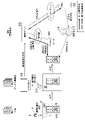
- FIG. 3 is an image diagram showing an outline of a work flow from when the battery switch 600 is shipped from the factory to when it is delivered to the operation site (hereinafter, simply referred to as “local”) and when it is initially set at the site.
- local the operation site
- FIG. 2 will be described with reference to the image diagram of FIG. 3 as appropriate.
- the battery switch 600 is not set assuming a specific country or business operator.
- the battery changer 600 is shipped from the factory with common settings for the whole world. Since the information necessary for connecting to the management server 500 (for example, the client certificate for connecting to the management server 500) is not registered in the battery exchange 600 in this state, the power is temporarily turned on in this state. Even so, the battery switch 600 cannot be used because it cannot access the management server 500.
- the battery exchange 600 stores device information that can identify itself in the storage unit 640 in advance, and the coded information indicating the device information is readable and attached to the factory.
- the coding information is described on the surface of the seal P attached to the predetermined position L on the surface of the box material B that packs the battery switch 600.
- the storage unit 640 of the battery exchange 600 has the same mark as the coding information M displayed on the seal P because the device information M is registered in the storage unit 640 of the battery exchange 600 in advance. It shows that it has been done.
- the device information registered in advance in the storage unit 640 of the battery switch 600 is an example of the first device information in the present invention.
- the factory-shipped battery switch 600 is delivered to, for example, the business office of the service provider.
- the service provider reads the coded information attached to the shipped battery switch 600 by the code reader 210 (step S101), and transmits the read device information to the management server 500 via the SP terminal 200 (step). S102).
- the management server 500 receives the device information transmitted by the SP terminal 200, and registers the received device information in the storage unit 540 (step S103). The processing up to this point is carried out by the time the on-site worker FW starts the on-site work.
- FIG. 4 is a diagram showing an example of device information in this embodiment.
- the device information is stored in the storage unit 540 of the management server 500 as a device information table T1 composed of one or more records having each value such as a device ID, a device name, a model number, a shipping date, a shipping source, and a shipping destination.
- the device ID represents the identification information of the battery switch 600 to be registered.
- the service provider delivers the battery switch 600 shipped from the factory to the site.
- the service provider dispatches a field worker FW to the site.
- the field worker FW goes to the site with the FW terminal 300 and performs preparatory work for initial setting for the battery exchange 600 delivered to the site.
- the field worker FW unpacks the battery switch 600, connects the battery switch 600 to a local power source, and turns on the power (step S104).
- the communication unit 610 performs a connection process with the router 400 (step S105), and the authentication unit 652 displays a password input screen for inputting a one-time password on the display unit 630. Display (step S106).
- the battery exchange 600 can communicate with the management server 500. This is due to, for example, the following management communication settings being made.
- FIG. 5 is a diagram showing an example of setting information regarding communication with the management server 500 set in the battery switch 600 at the time of shipment from the factory.
- the network ID is the identification information of the network provided by the router 400 installed in the field
- the connection password is the password for connecting to the network.
- the management server name represents the name of the management server 500 on the network.
- the battery switch 600 communicates with the management server 500 by setting a default gateway, a DSN server capable of resolving the management server name, and the like for the battery switch 600. It becomes possible.
- the field worker FW inputs an operation to acquire a one-time password to the FW terminal 300.
- the OTPW acquisition unit 351 requests the management server 500 to issue a one-time password (step S107).
- the OTPW issuing unit 552 issues a one-time password to the FW terminal 300 (step S108).
- the OTPW issuing unit 552 manages the issued one-time password so that it is valid for a predetermined period.
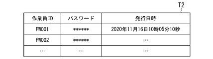
- FIG. 6 is a diagram showing an example of one-time password management in the present embodiment.
- the one-time password is stored in the storage unit 540 of the management server 500 as a password management table T2 composed of one or more records having each value of a worker ID, a password, and an issue date and time.
- the worker ID represents the identification information of the field worker who requested the issuance of the one-time password.
- the password represents the character string of the issued one-time password, and the issue date / time represents the date and time when the one-time password was issued.
- the OTPW acquisition unit 351 causes the display unit 330 to display the one-time password issued by the management server 500 (step S109).
- the field worker FW visually confirms the one-time password displayed on the display unit 330, and inputs it to the password input screen displayed on the battery switch 600.
- the input unit 620 accepts the input operation of the one-time password (step S110), and outputs the input information (hereinafter referred to as "password information") to the authentication unit 652.
- the authentication unit 652 generates authentication information based on the entered password information and the device information registered in advance in the storage unit 640 (step S111).
- the authentication information is information for requesting the management server 500 to authenticate the implementation of the initial setting, and is information including password information and device information.
- the authentication unit 652 requests the management server 500 to authenticate by transmitting the generated authentication information to the management server 500 (step S112).
- the device authentication unit 553 executes an authentication process that attempts to authenticate the requesting battery exchange 600 based on the authentication information received from the battery exchange 600 (step S113). For example, the device authentication unit 553 determines whether or not the password entered by the field worker is registered in the management server 500 as a valid one-time password based on the password information included in the authentication information, and also authenticates. It is determined whether or not the device information included in the information is registered in the management server 500. The device authentication unit 553 authenticates the requesting battery switch 600 when it is determined that both of these two determination results are true. The device authentication unit 553 determines whether or not the authentication of the battery switch 600 has been successful (step S114). Here, if it is determined that the authentication of the battery switch 600 has failed, the device authentication unit 553 performs a predetermined error process and ends a series of processes (step S115). In this case, the initial setting is not performed for the battery switch 600.
- step S114 if it is determined in step S114 that the authentication of the battery switch 600 has been successful, the device authentication unit 553 notifies the battery switch 600 to that effect (step S116: notification of initial setting start) and also informs the device setting unit 554. On the other hand, it is instructed to execute the initial setting process of the battery switch 600.
- the initial setting unit 653 of the battery exchange 600 Upon receiving the initial setting start notification, the initial setting unit 653 of the battery exchange 600 starts cooperation with the device setting unit 554 of the management server 500 and executes the initial setting process (step S117).
- the initial setting process on the battery switch 600 side is represented by step S117-1
- the initial setting process on the management server 500 side is represented by step S117-2.
- FIG. 7 is a diagram showing an example of initial setting information in this embodiment.
- the initial setting information is stored in the storage unit 540 of the management server 500 as the initial setting table T3 composed of one or more records having the model number and the value of the setting information of each item.
- the device setting unit 554 identifies the initial setting information to be set according to the model number of the battery changer 600 to be initialized.
- the initial setting unit 653 inquires the device setting unit 554 for the initial setting value to be set for each procedure to be executed, and the device setting unit 554 asks.
- the value set in the item according to the procedure being executed is returned to the initial setting unit 653. By repeating such inquiries and responses to execute all the procedures, the initial setting unit 653 completes the initial setting for the battery switch 600.
- the FW terminal 300 acquires a one-time password from the management server 500, and the battery switch 600 acquires the one-time password and the device information stored in advance. Based on this, the management server 500 is certified. Further, in the device management system 100 of the embodiment, the battery exchange 600 does not store the setting information for communicating with the management server 500 in advance, and can communicate with the management server 500 by connecting to the router 400 on site. It is configured to be. Further, in the device management system 100 of the embodiment, the device information stored in advance in the battery switch 600 is registered in the management server 500 before the battery switch 600 delivers to the site. By providing such a configuration, the device management system 100 of the embodiment can more easily perform initial setting of the device while ensuring sufficient security.
- the router 400 is an example of the first communication device in the present invention
- the FW terminal 300 is an example of the second communication device in the present invention.
- the OTPW issuing unit 552 is an example of the qualification information issuing unit in the present invention.
- the storage unit 540 of the management server 500 is an example of the first storage unit in the present invention.
- the storage unit 640 of the battery switch 600 is an example of the second storage unit in the present invention.
- Storage unit 550 ... Control unit , 551 ... Device information registration section, 552 ... OTPW issuing section, 552 ... Device authentication section, 554 ... Device setting section, 600 ... Battery switch, 601 ... Charger, 602 ... Drive section, 603 ... Power supply section, 610 ... Communication section , 620 ... Input unit, 630 ... Display unit, 640 ... Storage unit, 650 ... Control unit, 651 ... Drive control unit, 652 ... Authentication unit, 653 ... Initial setting unit
Landscapes
- Engineering & Computer Science (AREA)
- Computer Security & Cryptography (AREA)
- Theoretical Computer Science (AREA)
- Computer Hardware Design (AREA)
- Software Systems (AREA)
- Physics & Mathematics (AREA)
- General Engineering & Computer Science (AREA)
- General Physics & Mathematics (AREA)
- Telephonic Communication Services (AREA)
Abstract
Description
本願は、2020年12月11日に出願された日本国特願2020-205884号に基づき優先権を主張し、その内容をここに援用する。
(1):この発明の一態様に係る機器管理システムは、管理対象の機器と、前記機器との通信により前記機器の初期設定を行う管理装置と、を備え、前記管理装置は、前記機器が前記管理装置と通信する際に使用する第1の通信経路と、前記機器において前記初期設定を開始するために必要となる資格情報を取得する際に使用される通信経路であって前記第1の通信経路と異なる第2の通信経路と、のそれぞれを介して通信可能である、機器管理システムである。
Claims (11)
- 管理対象の機器と、
前記機器との通信により前記機器の初期設定を行う管理装置と、
を備え、
前記管理装置は、前記機器が前記管理装置と通信する際に使用する第1の通信経路と、前記機器において前記初期設定を開始するために必要となる資格情報を取得する際に使用される通信経路であって前記第1の通信経路と異なる第2の通信経路と、のそれぞれを介して通信可能である、
機器管理システム。 - 前記第1の通信経路は、前記機器および前記管理装置と通信可能に接続された第1の通信機器を含み、
前記第1の通信機器は、自身と接続した前記機器が、自身を介して前記管理装置と通信することができるようにするために必要な情報を保持する、
請求項1に記載の機器管理システム。 - 前記管理装置は、
前記機器の識別情報を含む機器情報を前記機器以外の装置から取得して第1の記憶部に記録する機器情報登録部を備え、
前記第1の記憶部に記録される前記機器情報は、画像認識処理により、前記機器に添付された画像から読み取られた情報である、
請求項1または2に記載の機器管理システム。 - 前記機器は、予め前記機器情報が記録されている第2の記憶部を備え、
前記機器情報登録部は、前記第2の記憶部に記録されている前記機器情報を前記第1の通信経路を介して前記機器から取得し、
前記管理装置は、前記機器情報登録部が前記第1の記憶部に記録した機器情報と、前記第1の通信経路を介して前記機器から取得された機器情報とに基づいて前記機器の認証を行う認証部をさらに備える、
請求項3に記載の機器管理システム。 - 前記機器は、前記管理装置との通信により前記初期設定を行う初期設定部をさらに備え、
前記管理装置は、前記初期設定部と連携して前記機器の初期設定を行う機器設定部をさらに備え、
前記初期設定部および前記機器設定部は、前記認証部によって前記機器が認証された場合に前記初期設定に関する連携を開始する、
請求項4に記載の機器管理システム。 - 前記初期設定部は、前記第2の通信経路を介して前記管理装置から取得された前記資格情報を、前記第2の記憶部に記録されている前記機器情報とともに前記管理装置に送信し、
前記認証部は、前記機器から受信された前記機器情報と、前記第1の記憶部に記録されている前記機器情報と、前記機器から受信された前記資格情報とに基づいて前記機器の認証を行う、
請求項5に記載の機器管理システム。 - 前記第2の通信経路は、前記管理装置と通信可能に接続された第2の通信機器を含む、
請求項3から6のいずれか一項に記載の機器管理システム。 - 前記管理装置は、前記第2の通信経路を介して前記第2の通信機器に前記資格情報を提供する資格情報発行部をさらに備える、
請求項7に記載の機器管理システム。 - 管理装置との通信により自身の初期設定を行う通信機器であって、
第1の通信経路を介した通信により前記管理装置と連携して前記通信機器の初期設定を行う初期設定部と、
前記通信機器の識別情報を含む機器情報を記憶する記憶部と、
第2の通信経路を介して得られた資格情報であって、前記初期設定の開始に必要となる資格情報の入力を受け付ける入力部と、
前記資格情報が入力されたことに応じて前記管理装置に前記通信機器の認証を要求する認証部と、
前記管理装置によって前記通信機器が認証された場合に、前記管理装置との間で前記初期設定に関する連携を開始する初期設定部と、
を備える通信機器。 - 通信機器との通信により前記通信機器の初期設定を行う管理装置であって、
第1の通信経路を介した通信により前記通信機器と連携して前記通信機器の初期設定を行う機器設定部と、
前記通信機器の識別情報を含む機器情報を前記通信機器以外の装置から取得して記憶部に記録する機器情報登録部と、
前記通信機器が前記初期設定を開始するために必要となる資格情報を第2の通信経路を介して発行する資格情報発行部と、
前記通信機器に予め記憶されている第1の機器情報と、前記通信機器に入力された資格情報とが前記通信機器から取得された場合に、前記第1の機器情報および前記資格情報と、前記機器情報登録部によって登録された第2の機器情報とに基づいて前記通信機器を認証する認証部と、
を備え、
前記機器設定部は、前記認証部によって前記通信機器が認証された場合に、前記通信機器との間で前記初期設定に係る連携を開始する、
管理装置。 - 管理装置と、前記管理装置の管理対象となる機器とが、前記機器の初期設定に関する通信を第1の通信経路を介して行い、
前記管理装置が、前記機器において前記初期設定を開始するために必要となる資格情報を、前記第1の通信経路と異なる第2の通信経路を介して提供する、
機器管理方法。
Priority Applications (2)
| Application Number | Priority Date | Filing Date | Title |
|---|---|---|---|
| JP2022568180A JPWO2022124103A1 (ja) | 2020-12-11 | 2021-11-26 | |
| JP2025029252A JP2025084848A (ja) | 2020-12-11 | 2025-02-26 | 機器管理システム、管理装置、通信機器、および機器管理方法 |
Applications Claiming Priority (2)
| Application Number | Priority Date | Filing Date | Title |
|---|---|---|---|
| JP2020205884 | 2020-12-11 | ||
| JP2020-205884 | 2020-12-11 |
Publications (1)
| Publication Number | Publication Date |
|---|---|
| WO2022124103A1 true WO2022124103A1 (ja) | 2022-06-16 |
Family
ID=81973189
Family Applications (1)
| Application Number | Title | Priority Date | Filing Date |
|---|---|---|---|
| PCT/JP2021/043453 Ceased WO2022124103A1 (ja) | 2020-12-11 | 2021-11-26 | 機器管理システム、管理装置、通信機器、および機器管理方法 |
Country Status (2)
| Country | Link |
|---|---|
| JP (2) | JPWO2022124103A1 (ja) |
| WO (1) | WO2022124103A1 (ja) |
Citations (3)
| Publication number | Priority date | Publication date | Assignee | Title |
|---|---|---|---|---|
| JP2012226394A (ja) * | 2011-04-14 | 2012-11-15 | Sii Data Service Kk | 端末設置システム及び端末設置方法 |
| JP2019016880A (ja) * | 2017-07-05 | 2019-01-31 | 富士通株式会社 | ネットワーク機器、ネットワークシステム及びネットワーク機器設定方法 |
| JP2019097027A (ja) * | 2017-11-22 | 2019-06-20 | 株式会社ノーリツ | 通信システム、通信システムの制御方法、及び、中継装置 |
Family Cites Families (1)
| Publication number | Priority date | Publication date | Assignee | Title |
|---|---|---|---|---|
| JP6838009B2 (ja) * | 2018-02-28 | 2021-03-03 | 株式会社東芝 | 通信制御装置および通信制御方法 |
-
2021
- 2021-11-26 WO PCT/JP2021/043453 patent/WO2022124103A1/ja not_active Ceased
- 2021-11-26 JP JP2022568180A patent/JPWO2022124103A1/ja active Pending
-
2025
- 2025-02-26 JP JP2025029252A patent/JP2025084848A/ja active Pending
Patent Citations (3)
| Publication number | Priority date | Publication date | Assignee | Title |
|---|---|---|---|---|
| JP2012226394A (ja) * | 2011-04-14 | 2012-11-15 | Sii Data Service Kk | 端末設置システム及び端末設置方法 |
| JP2019016880A (ja) * | 2017-07-05 | 2019-01-31 | 富士通株式会社 | ネットワーク機器、ネットワークシステム及びネットワーク機器設定方法 |
| JP2019097027A (ja) * | 2017-11-22 | 2019-06-20 | 株式会社ノーリツ | 通信システム、通信システムの制御方法、及び、中継装置 |
Also Published As
| Publication number | Publication date |
|---|---|
| JPWO2022124103A1 (ja) | 2022-06-16 |
| JP2025084848A (ja) | 2025-06-03 |
Similar Documents
| Publication | Publication Date | Title |
|---|---|---|
| JP6451750B2 (ja) | 仮想ネットワークシステム、仮想ネットワーク制御方法、仮想ネットワーク機能データベース、統合制御装置、制御装置およびその制御方法と制御プログラム | |
| EP3104549B1 (en) | Home appliance, network connection system for home appliance and network connection method of home appliance | |
| JP3946700B2 (ja) | 目的のネットワーク環境に対するネットワーク装置のアドレス可能性の自動確立のための方法および装置 | |
| US20220052858A1 (en) | Virtual network system, control apparatus, control method, and control program | |
| JP5030681B2 (ja) | 機器設定装置、ネットワーク機器、機器名設定方法および機器名設定プログラム | |
| CN101201727A (zh) | 通过网络的打印机选择支持装置及系统 | |
| US9703969B2 (en) | Image forming system, service providing server, information processing terminal, image forming device and non-transitory computer readable recording medium | |
| CN105230039B (zh) | 室内控制器以及远程控制系统 | |
| JP6670782B2 (ja) | 通信装置、通信方法、機器およびコンピュータプログラム | |
| JP2019075802A (ja) | 仮想ネットワーク制御方法、提供者端末、登録更新制御装置およびそのプログラム | |
| CN113498494A (zh) | 安全系统和维护方法 | |
| CN104346111A (zh) | 信息处理系统、信息处理装置和信息处理方法 | |
| JP5232300B2 (ja) | 中央コンピュータとマシン制御部との間でリモート通信を行うためのシステムおよび方法 | |
| JP2015133567A (ja) | 携帯通信端末、管理サーバ、電子チケットシステム、及びプログラム | |
| WO2022124103A1 (ja) | 機器管理システム、管理装置、通信機器、および機器管理方法 | |
| KR20130116938A (ko) | 중계 통신 시스템 | |
| US10067486B2 (en) | System and method for providing a control program code | |
| CN112004978B (zh) | 密钥信息生成系统及密钥信息生成方法 | |
| JP7586763B2 (ja) | 遠隔操作制御システム及びプログラム | |
| WO2015125952A1 (ja) | 電子機器制御システム、電子機器制御システムの動作方法、サーバ、サーバの動作方法、コントローラ、コントローラの動作方法及びプログラム | |
| JP6734443B2 (ja) | 情報処理装置、情報処理方法、コンピュータプログラム及び情報処理システム | |
| JP2024013980A (ja) | 通信システム、制御装置、通信方法、及びプログラム | |
| JP2013214825A (ja) | 中継装置、通信制御方法及び通信制御プログラム | |
| JP6750260B2 (ja) | 情報処理装置およびエージェントシステム | |
| US20190043044A1 (en) | Method of data transmission, corresponding device, system and computer program |
Legal Events
| Date | Code | Title | Description |
|---|---|---|---|
| 121 | Ep: the epo has been informed by wipo that ep was designated in this application |
Ref document number: 21903207 Country of ref document: EP Kind code of ref document: A1 |
|
| ENP | Entry into the national phase |
Ref document number: 2022568180 Country of ref document: JP Kind code of ref document: A |
|
| WWE | Wipo information: entry into national phase |
Ref document number: 202347041747 Country of ref document: IN |
|
| NENP | Non-entry into the national phase |
Ref country code: DE |
|
| 122 | Ep: pct application non-entry in european phase |
Ref document number: 21903207 Country of ref document: EP Kind code of ref document: A1 |