WO2022123625A1 - ワーク保持装置 - Google Patents
ワーク保持装置 Download PDFInfo
- Publication number
- WO2022123625A1 WO2022123625A1 PCT/JP2020/045472 JP2020045472W WO2022123625A1 WO 2022123625 A1 WO2022123625 A1 WO 2022123625A1 JP 2020045472 W JP2020045472 W JP 2020045472W WO 2022123625 A1 WO2022123625 A1 WO 2022123625A1
- Authority
- WO
- WIPO (PCT)
- Prior art keywords
- work
- holding device
- work holding
- peripheral surface
- core member
- Prior art date
- Legal status (The legal status is an assumption and is not a legal conclusion. Google has not performed a legal analysis and makes no representation as to the accuracy of the status listed.)
- Ceased
Links
Images


Classifications
-
- B—PERFORMING OPERATIONS; TRANSPORTING
- B23—MACHINE TOOLS; METAL-WORKING NOT OTHERWISE PROVIDED FOR
- B23B—TURNING; BORING
- B23B31/00—Chucks; Expansion mandrels; Adaptations thereof for remote control
- B23B31/02—Chucks
- B23B31/10—Chucks characterised by the retaining or gripping devices or their immediate operating means
- B23B31/12—Chucks with simultaneously-acting jaws, whether or not also individually adjustable
- B23B31/16—Chucks with simultaneously-acting jaws, whether or not also individually adjustable moving radially
-
- B—PERFORMING OPERATIONS; TRANSPORTING
- B23—MACHINE TOOLS; METAL-WORKING NOT OTHERWISE PROVIDED FOR
- B23Q—DETAILS, COMPONENTS, OR ACCESSORIES FOR MACHINE TOOLS, e.g. ARRANGEMENTS FOR COPYING OR CONTROLLING; MACHINE TOOLS IN GENERAL CHARACTERISED BY THE CONSTRUCTION OF PARTICULAR DETAILS OR COMPONENTS; COMBINATIONS OR ASSOCIATIONS OF METAL-WORKING MACHINES, NOT DIRECTED TO A PARTICULAR RESULT
- B23Q3/00—Devices holding, supporting, or positioning work or tools, of a kind normally removable from the machine
- B23Q3/02—Devices holding, supporting, or positioning work or tools, of a kind normally removable from the machine for mounting on a work-table, tool-slide, or analogous part
- B23Q3/06—Work-clamping means
-
- B—PERFORMING OPERATIONS; TRANSPORTING
- B23—MACHINE TOOLS; METAL-WORKING NOT OTHERWISE PROVIDED FOR
- B23B—TURNING; BORING
- B23B2270/00—Details of turning, boring or drilling machines, processes or tools not otherwise provided for
- B23B2270/06—Use of elastic deformation
-
- B—PERFORMING OPERATIONS; TRANSPORTING
- B23—MACHINE TOOLS; METAL-WORKING NOT OTHERWISE PROVIDED FOR
- B23B—TURNING; BORING
- B23B2270/00—Details of turning, boring or drilling machines, processes or tools not otherwise provided for
- B23B2270/12—Centering of two components relative to one another
-
- B—PERFORMING OPERATIONS; TRANSPORTING
- B23—MACHINE TOOLS; METAL-WORKING NOT OTHERWISE PROVIDED FOR
- B23B—TURNING; BORING
- B23B2270/00—Details of turning, boring or drilling machines, processes or tools not otherwise provided for
- B23B2270/20—Internally located features, machining or gripping of internal surfaces
- B23B2270/205—Machining or gripping both internal and external surfaces
Definitions
- the present invention relates to a work holding device.
- carbon scraper ring As a functional component for scraping off hard carbon accumulated on the piston in diesel engines, carbon scraper ring is installed on the upper part of the cylinder liner (top dead center position on the piston top land) in the engine and scrapes off the hard carbon when the piston rises. It's being used. Carbon scraping that functions in this way may be required to be thin.
- Patent Documents 1 and 2 Various devices have been proposed for producing thin-walled metal ring-shaped members such as carbon scraper rings (see Patent Documents 1 and 2), for example, the end portion of a thin-walled cylindrical workpiece.
- a device is used for chucking and cantilevering support, and sequentially cutting the unsupported side (product part) by parting or the like to form, for example, 10 to 20 rings.
- it is particularly important to chuck the work without causing strain and to prevent chattering during processing.
- the machining process is divided (instead of cutting out a predetermined number of rings from the work by one chucking (one chuck), for example, (1) outer diameter machining ⁇ inner diameter machining ⁇ Cutting-> one-sided chamfering-> the other chamfering, a total of 5 chucks, or (2) cutting-> outer diameter processing-> inner diameter processing-> one-sided chamfering-> the other chamfering, a total of 5 chucks.
- chucking is repeated).
- it may be difficult to secure accuracy such as inner chamfering, inner / outer diameter coaxiality, and roundness due to the influence of chuck accuracy.
- an object of the present invention is to provide a work holding device capable of processing a thin-walled cylindrical work with higher accuracy.
- One aspect of the present invention is a device for holding a held portion at an axial end portion of a cylindrical workpiece.
- a circular core member that abuts on the inner peripheral surface of the held portion of the work,
- a pressing member that presses the outer peripheral surface of the held portion of the work inward in the radial direction,
- An alignment member that allows the core member to move in the radial direction according to the magnitude and direction of the pressing force when the pressing force applied by the pressing member is applied. It is a work holding device.
- the work In a work holding device that presses the outer peripheral surface and the inner peripheral surface of the axial end of the work with a pressing member and a core member to chuck and cantilever support the work, the work is not a perfect circle or has a uniform thickness. If it is not present, the processing accuracy may be affected, which is even more so as the work is thinner.
- the core member moves in the radial direction according to the magnitude and direction of the pressing force from the outside by the pressing member to equalize (each member and the work are concentric). Position correction to achieve this, homogenization / homogenization of the pressing force distribution), and suppression of workpiece deformation during chucking and chattering during machining. According to this, it becomes possible to process a thin-walled cylindrical work with higher accuracy.
- the centering member may be composed of an elastic member that deforms according to the magnitude and direction of the pressing force of the pressing member.
- the work holding device of the above-described embodiment further includes a mounting bolt for mounting the core member at a predetermined position of the work holding device, and a sleeve-shaped elastic member arranged around the mounting bolt is adjusted. It may be used as a core member.
- the sleeve-shaped elastic member in the work holding device of the above-described embodiment may be made of resin, rubber, or silicone.
- the mounting bolt in the work holding device of the above-described embodiment is a stepped bolt that is inserted into a through hole provided in the core member, and the elastic member matches the shape of the gap between the through hole and the mounting bolt. May be formed.
- a plurality of members may be arranged at equal intervals in the circumferential direction.
- the pressing member may include a gripper portion that improves the frictional force with the held portion of the work.
- the portion of the peripheral surface of the core member that comes into contact with the inner peripheral surface of the work may be tapered.
- the held portion of the work is a portion excluding the portion that becomes the final product, and the inner peripheral surface of the held portion is tapered to match the tapered peripheral surface of the core member.
- a workpiece whose portion has been preprocessed may be a holding target.
- the work holding device of the above-described embodiment further includes a device for pulling the work in the axial direction, and an inclined wall surface for applying a component force toward the radial inward side of the work on the pressing member when the work is pulled by the pulling device. May be good.
- a thin cylindrical work can be machined with higher accuracy.
- FIG. 3 is an enlarged view showing the periphery of the claw member of the chuck portion of the work holding device shown in FIG. It is a vertical sectional view which shows the chuck part of the work holding device in the state which the chuck by the claw member is opened.
- FIG. 5 is an enlarged view showing the periphery of the claw member of the chuck portion of the work holding device shown in FIG. It is a vertical cross-sectional view which shows the chuck part of the work holding device in the state which held the work, and also in the state which the core member moved in the radial direction.
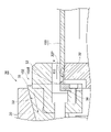
- FIG. 7 is an enlarged view showing the periphery of the claw member and the elastic member (alignment member) of the chuck portion of the work holding device shown in FIG. 7.
- FIG. 8 is an enlarged view showing a part of FIG. 8 (a part surrounded by a circle with reference numeral A).
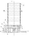
- the work holding device 10 shown in FIG. 1 and the like is a device that holds the held portion 110 at the base end portion 102 of the work 100.
- the work 100 held by this device is a thin cylindrical work, and in the held state, the product part (the part to be processed into a product) 120 is sequentially cut out from the tip portion 101 side, and carbon scraping is performed. It is processed into a thin metal ring-shaped member 200 (indicated by a broken line in FIG. 1 and the like).
- the side of the tip portion 101 is referred to as the "tip end side” and the side of the base end portion 102 is referred to as the "base end side” along the axial direction of the work 100 held by the work holding device 10 ( See Fig. 1 etc.).
- the virtual central axis when the work 100 is held by the work holding device 10 is indicated by reference numeral C (see FIG. 1 and the like).
- the work holding device 10 of the present embodiment is composed of a device main body portion 20 and a chuck portion 30 (see FIG. 1 and the like).
- the device main body 20 draws the chuck 30 along the axial direction of the work 100 to the base end side (the side where the device main body 20 is located) via the pipe 24, for example, a hydraulic pulling device (indicated by reference numeral 21 in FIG. 1). ) Is provided.
- a pull-in device 21 a known device that has been used conventionally (details thereof will be omitted in the present specification) can be applied.
- Reference numeral 23 is a liquid supply pipe for supplying the cutting fluid for flowing out the chips on the inner circumference of the work 100 toward the tip side when the work 100 is machined (see FIG. 1 and the like). ).
- the apparatus main body 20 is formed with an inclined wall surface 22 to which a part of the chuck portion 30 abuts (see FIG. 1 and the like).
- the inclined wall surface 22 is composed of, for example, a tapered surface that narrows toward the proximal end side and has a smaller diameter.
- the chuck portion 30 is provided so as to chuck and hold the work 100 and to be retractable toward the base end side by the retracting device 21.
- the chuck portion 30 in the work holding device 10 of the present embodiment includes a base member 31, a core member 32, a claw member 33, a work gripper 34, an intermediate member 35, a stopper 36, a mounting bolt 42, an elastic member 44, and the like. (See Fig. 2, Fig. 3, etc.).
- the base member 31 is attached and fixed to the device main body 20 with bolts (not shown in particular) (see FIG. 1 and the like).
- the core member 32 is attached to the base member 31 in a state where it can move in the radial direction (direction perpendicular to the virtual center axis C) relative to the base member 31.
- the core member 32 is a circular member seen from the axial direction that abuts on the inner peripheral surface of the held portion 110 of the work 100.
- a tapered core is adopted in which the portion of the peripheral surface 32P of the core member 32 that abuts on the inner peripheral surface of the work 100 has a tapered shape having a larger diameter toward the proximal end side (Fig.). See 1st class).
- the work 100 can be easily attached to and detached from the core member 32 as compared with the fitted core having a peripheral surface having a uniform diameter.
- a work 100 may be adopted in which the inner peripheral surface of the held portion 110 is preprocessed with a tapered portion 100t that matches the tapered peripheral surface 32P of the core member 32 (see FIG. 8 and the like). ).
- the core member 32 is provided with a through hole 32H through which the mounting bolt 42 is passed (see FIG. 5 and the like).
- the claw member 33 is a member that functions as a pressing member that presses the outer peripheral surface of the held portion 110 of the work 100 inward in the radial direction, and a plurality (for example, three) are at equal intervals (every 120 °) in the circumferential direction. Arranged (see Figure 2). Each claw member 33 is provided so as to be movable in the radial direction by a claw guide (not shown) formed on the intermediate member 35 (see FIG. 2 and the like). Each of these claw members 33 is provided so as to interlock with the intermediate member 35 (see FIGS.
- the claw member 33 having a bifurcated claw is adopted in the present embodiment, in the vertical cross-sectional view such as FIG. 7, the mounting bolt 33A of the claw member 33 and the mounting bolt 33A are passed through. It is difficult to understand because the hole 33B appears in the drawing and the portion where the claw member 33 is in contact with the outer peripheral surface of the work 100 is not shown, but in reality, the claw member is located on both sides of the hole 33B in the circumferential direction. 33 is in contact with the outer peripheral surface of the work 100.
- the work gripper (gripper portion) 34 is a member that improves the holding force of the work 100 in the chuck portion 30.
- the super hard spike provided inside or near the claw member 33 is moved inward in the radial direction, and the end portion thereof is pressed against the outer peripheral surface of the work 100 to increase the frictional force and slip during rotation.
- a work gripper 34 having a structure capable of suppressing the above is adopted (see FIG. 1 and the like).
- the intermediate member 35 is a member that exerts a component force inward in the radial direction on the claw member 33 by the wedge action of the inclined wall surface 22 as the chuck portion 30 is pulled toward the device main body portion 20 by the pulling device 21. Yes (see Fig. 4 etc.).
- the stopper 36 is a member provided at a position where the edge portion 102E on the base end portion 102 side of the work 100 abuts, and is used when the base end portion 102 of the work 100 is fitted between the core member 32 and the claw member 33.
- the axial position of the work 100 is defined.
- the tip portion 101 of the work 100 is urged toward the base end portion 102 by an urging device (not shown) composed of a spring, an abutting plate, or the like, and is not chucked by the chuck portion 30.
- the edge portion 102E of the work 100 in the state is brought into contact with the stopper 36, and the axial position of the work 100 is defined to maintain the posture.
- the chuck portion 30 is pulled toward the base end side (the side where the device main body portion 20 is located) in a state where the axial position of the work 100 is defined by the stopper 36, and the claw member 33 and the core member 32 are used by using the wedge action.
- the stopper 36 moves to the base end side, and the edge portion 102E is separated from the stopper 36 (see FIGS. 3 and 4).
- the stopper 36 may hit the edge portion 102E and push it toward the tip side (FIGS. 5 and 5). 6).
- the mounting bolt 42 is a bolt used for mounting the core member 32 to the base member 31.
- a plurality of (for example, three) mounting bolts 42 and through holes 32H for passing them are provided at equal intervals (every 120 °) in the circumferential direction, and each claw does not overlap with the claw member 33. They are arranged at equal intervals with respect to the member 33 (every 60 ° with respect to each claw member 33) (see FIGS. 2 and 5).
- a stepped bolt may be adopted as the mounting bolt 42.
- a stepped bolt in which the threaded portion 42a is screwed into the screw hole 31H of the base member 31 and the stepped portion 42b abuts on the end surface around the screw hole 31H of the base member 31 is used as the mounting bolt 42. 1 and 7-9). According to such a mounting bolt 42, it is easy to homogenize the mounting depth, tightening torque, and the like of the bolt.
- the through hole 32H of the core member 32 is provided as a hole through which the screw portion 42a of the mounting bolt 42 is passed and which accommodates the shaft portion 42c and the head portion 42d.
- the through hole 32H has a stepped shape that matches the shape of the shaft portion 42c and the head portion 42d of the mounting bolt 42, and has an inner diameter that is somewhat larger than the shaft portion 42c and the head portion 42d. It is formed of holes so that a predetermined gap is formed between the mounting bolt 42 and the through hole 32H (see FIG. 9 and the like). An elastic member 44 is provided in this gap.
- the elastic member 44 of the present embodiment is formed in a sleeve shape and is arranged around the mounting bolt 42. Further, corresponding to the stepped shape of the mounting bolt 42 and the through hole 32H, in the present embodiment, two types of sleeve-shaped elastic members having different diameters are arranged around the mounting bolt 42 (in this embodiment). See Fig. 9 etc.). One of these two types of sleeve-shaped elastic members is sandwiched between the step portion of the through hole 32H and the head portion 42d of the mounting bolt 42 and functions like a seat (see FIG. 9).
- the work holding device 10 of the present embodiment realizes the following centering function. That is, when the chuck portion 30 is pulled in by the pulling device 21, a pressing force acts from the outer periphery of the work 100 from the claw member 33 due to the wedge effect of the inclined wall surface 22, and the claw member 33 and the core member 32 cover the work 100.
- the holding portion 110 is chucked (see FIG. 4 and the like). At this time, if the pressing force acting on the work 100 acting between the claw member 33 and the core member 32 is uniform, there is no significant effect, but if the pressing force is not uniform due to a difference in processing accuracy of the work 100 or the like.
- a radial force acts on the core member 32 depending on the non-uniformity.
- the elastic member 44 is elastically deformed by the force, and the core member 32 is radially deformed by the correction amount a (see FIG. 8) according to the magnitude and direction of the force.
- the so-called equalization position correction for concentric circles of each member and work, homogenization / homogenization of pressing force distribution
- the work 100 is not a perfect circle or has a thickness.
- the work holding device 10 having the equalizing function as described above eliminates such an influence as much as possible and works at the time of chucking. It is possible to suppress deformation of 100 and chattering during processing. Further, in the case of cantilever support, it is necessary to increase the chuck force (pushing pressure) and the work rigidity in order to suppress the risk of chattering during machining and the work coming off. According to the work holding device 10, deformation of the work 100 is suppressed even if the chucking force is increased, the work 100 is firmly held, and chattering does not occur. Based on the above, it is possible to process thin-walled cylindrical workpieces with higher accuracy.
- the machining process is divided (rather than cutting out a predetermined number of rings from the workpiece with one chucking, chucking and ring cutting are repeated).
- the work holding device 10 of the present embodiment it is possible to accurately process a thin-walled cylindrical work with only one chuck without dividing the processing process as in this method.
- the thin-walled cylindrical work 100 can be machined more accurately, so that the carbon scraper manufactured by the work processing is possible. Since it is possible to suppress the deformation of the metal ring-shaped member 200 such as a ring to secure the roundness, and (ii) it is possible to suppress the deformation of the work 100 at the time of chucking and the chattering at the time of processing. A large number of metal ring-shaped members 200 can be efficiently cut out from one work 100 having a longer overall length than that of the work 100. The work 100 can be automatically attached / detached by using the claw member 33 of the mechanism that moves diagonally.
- the present invention is not limited to this, and various modifications can be carried out without departing from the gist of the present invention.
- the elastic member 44 provided around the mounting bolt 42 is shown as an example of the centering member, but the above-mentioned elastic member 44 is only a suitable example in terms of shape, material, and structure. It goes without saying that other members that perform the above functions, such as members made of rubber or silicone, can be applied.
- the present invention is suitable for application to various work holding devices including work holding devices in robots, NCs and loaders.
Landscapes
- Engineering & Computer Science (AREA)
- Mechanical Engineering (AREA)
- Jigs For Machine Tools (AREA)
- Gripping On Spindles (AREA)
- Gear Processing (AREA)
Priority Applications (4)
| Application Number | Priority Date | Filing Date | Title |
|---|---|---|---|
| CN202080107784.1A CN116568437B (zh) | 2020-12-07 | 2020-12-07 | 工件保持装置 |
| US18/265,958 US20230373012A1 (en) | 2020-12-07 | 2020-12-07 | Workpiece retaining device |
| PCT/JP2020/045472 WO2022123625A1 (ja) | 2020-12-07 | 2020-12-07 | ワーク保持装置 |
| JP2022512290A JP7564866B2 (ja) | 2020-12-07 | 2020-12-07 | ワーク保持装置 |
Applications Claiming Priority (1)
| Application Number | Priority Date | Filing Date | Title |
|---|---|---|---|
| PCT/JP2020/045472 WO2022123625A1 (ja) | 2020-12-07 | 2020-12-07 | ワーク保持装置 |
Publications (1)
| Publication Number | Publication Date |
|---|---|
| WO2022123625A1 true WO2022123625A1 (ja) | 2022-06-16 |
Family
ID=81974308
Family Applications (1)
| Application Number | Title | Priority Date | Filing Date |
|---|---|---|---|
| PCT/JP2020/045472 Ceased WO2022123625A1 (ja) | 2020-12-07 | 2020-12-07 | ワーク保持装置 |
Country Status (4)
| Country | Link |
|---|---|
| US (1) | US20230373012A1 (https=) |
| JP (1) | JP7564866B2 (https=) |
| CN (1) | CN116568437B (https=) |
| WO (1) | WO2022123625A1 (https=) |
Cited By (1)
| Publication number | Priority date | Publication date | Assignee | Title |
|---|---|---|---|---|
| JP7713069B1 (ja) * | 2024-06-28 | 2025-07-24 | Dmg森精機株式会社 | チャック装置 |
Citations (8)
| Publication number | Priority date | Publication date | Assignee | Title |
|---|---|---|---|---|
| JPS5314453Y2 (https=) * | 1973-06-15 | 1978-04-17 | ||
| JPS62159209U (https=) * | 1986-03-31 | 1987-10-09 | ||
| JPH04102708U (ja) * | 1991-02-15 | 1992-09-04 | 日野自動車工業株式会社 | チヤツク |
| JPH07156005A (ja) * | 1993-12-03 | 1995-06-20 | Nikon Corp | 薄肉ワークの固定装置 |
| JPH0966401A (ja) * | 1995-06-21 | 1997-03-11 | Canon Inc | 円筒部材およびその製造方法ならびに製造装置 |
| US5970829A (en) * | 1998-10-30 | 1999-10-26 | Hayes Lemmerz International, Inc. | Apparatus and method for machining a hollow generally cylindrical workpiece |
| JP2000142558A (ja) * | 1998-11-16 | 2000-05-23 | Create Kyushu:Kk | ブロック搭載用吊りピ―スの切断方法 |
| CN209407460U (zh) * | 2018-12-25 | 2019-09-20 | 平湖市众川机械有限公司 | 一种夹持圆筒状工件的三爪卡盘 |
Family Cites Families (1)
| Publication number | Priority date | Publication date | Assignee | Title |
|---|---|---|---|---|
| JP2597119B2 (ja) * | 1987-12-17 | 1997-04-02 | 株式会社フジユニバンス | 工作機用チャックの取付け爪連結装置 |
-
2020
- 2020-12-07 JP JP2022512290A patent/JP7564866B2/ja active Active
- 2020-12-07 WO PCT/JP2020/045472 patent/WO2022123625A1/ja not_active Ceased
- 2020-12-07 CN CN202080107784.1A patent/CN116568437B/zh active Active
- 2020-12-07 US US18/265,958 patent/US20230373012A1/en active Pending
Patent Citations (8)
| Publication number | Priority date | Publication date | Assignee | Title |
|---|---|---|---|---|
| JPS5314453Y2 (https=) * | 1973-06-15 | 1978-04-17 | ||
| JPS62159209U (https=) * | 1986-03-31 | 1987-10-09 | ||
| JPH04102708U (ja) * | 1991-02-15 | 1992-09-04 | 日野自動車工業株式会社 | チヤツク |
| JPH07156005A (ja) * | 1993-12-03 | 1995-06-20 | Nikon Corp | 薄肉ワークの固定装置 |
| JPH0966401A (ja) * | 1995-06-21 | 1997-03-11 | Canon Inc | 円筒部材およびその製造方法ならびに製造装置 |
| US5970829A (en) * | 1998-10-30 | 1999-10-26 | Hayes Lemmerz International, Inc. | Apparatus and method for machining a hollow generally cylindrical workpiece |
| JP2000142558A (ja) * | 1998-11-16 | 2000-05-23 | Create Kyushu:Kk | ブロック搭載用吊りピ―スの切断方法 |
| CN209407460U (zh) * | 2018-12-25 | 2019-09-20 | 平湖市众川机械有限公司 | 一种夹持圆筒状工件的三爪卡盘 |
Cited By (1)
| Publication number | Priority date | Publication date | Assignee | Title |
|---|---|---|---|---|
| JP7713069B1 (ja) * | 2024-06-28 | 2025-07-24 | Dmg森精機株式会社 | チャック装置 |
Also Published As
| Publication number | Publication date |
|---|---|
| CN116568437A (zh) | 2023-08-08 |
| CN116568437B (zh) | 2025-02-25 |
| JP7564866B2 (ja) | 2024-10-09 |
| US20230373012A1 (en) | 2023-11-23 |
| JPWO2022123625A1 (https=) | 2022-06-16 |
Similar Documents
| Publication | Publication Date | Title |
|---|---|---|
| JP4625218B2 (ja) | 特に中空の薄壁状の工作物のための緊締装置 | |
| EP3202516B1 (en) | Chuck structure | |
| CN104551072B (zh) | 双锥斜楔自定心夹具 | |
| WO2015108174A1 (ja) | 両頭平面研削装置および研削方法 | |
| JP3446921B2 (ja) | ワーク把持装置 | |
| JPS58120404A (ja) | 旋盤 | |
| WO2022123625A1 (ja) | ワーク保持装置 | |
| JP2010194635A (ja) | クランプ装置 | |
| CN109108697B (zh) | 一种薄壁弹性支承及其工装、加工方法 | |
| JP4393214B2 (ja) | チャック装置 | |
| JP4768382B2 (ja) | 芯押台 | |
| JP5376161B2 (ja) | コレットチャック | |
| CN217618201U (zh) | 一种齿轮磨齿加工夹具 | |
| US11583940B2 (en) | Clamping device for clamping a tool or work piece | |
| CN113646129B (zh) | 液压式夹紧装置及套环部件 | |
| JP5883407B2 (ja) | 位置調整用治具、それを含むチャック装置を備えた工作機械、それを含むチャック装置を備えた検査器、および、それに用いられる可変形部材 | |
| CN112276605A (zh) | 机座加工工装及机座加工工艺 | |
| RU2858164C1 (ru) | Двойная цанга для закрепления полого цилиндрического корпуса на токарном станке | |
| RU2858163C2 (ru) | Устройство для закрепления цилиндрического корпуса на токарном станке | |
| JP4776346B2 (ja) | コレットチャック装置 | |
| JP4067892B2 (ja) | 工作物保持装置および保持方法 | |
| JP2008149409A (ja) | 円筒研削盤のチャック装置 | |
| CN114260736B (zh) | 薄壁台阶盖板用开口套及薄壁台阶盖板加工方法 | |
| RU2248862C1 (ru) | Резьбовая оправка | |
| JPH0819908A (ja) | 外径コレットチャック |
Legal Events
| Date | Code | Title | Description |
|---|---|---|---|
| ENP | Entry into the national phase |
Ref document number: 2022512290 Country of ref document: JP Kind code of ref document: A |
|
| 121 | Ep: the epo has been informed by wipo that ep was designated in this application |
Ref document number: 20965011 Country of ref document: EP Kind code of ref document: A1 |
|
| WWE | Wipo information: entry into national phase |
Ref document number: 202080107784.1 Country of ref document: CN |
|
| WWE | Wipo information: entry into national phase |
Ref document number: 202317040544 Country of ref document: IN |
|
| NENP | Non-entry into the national phase |
Ref country code: DE |
|
| 122 | Ep: pct application non-entry in european phase |
Ref document number: 20965011 Country of ref document: EP Kind code of ref document: A1 |
|
| WWG | Wipo information: grant in national office |
Ref document number: 202080107784.1 Country of ref document: CN |