WO2022118515A1 - 溶接鋼管のシーム部および加熱部の位置検出装置、溶接鋼管の製造設備、溶接鋼管のシーム部および加熱部の位置検出方法、溶接鋼管の製造方法および溶接鋼管の品質管理方法 - Google Patents
溶接鋼管のシーム部および加熱部の位置検出装置、溶接鋼管の製造設備、溶接鋼管のシーム部および加熱部の位置検出方法、溶接鋼管の製造方法および溶接鋼管の品質管理方法 Download PDFInfo
- Publication number
- WO2022118515A1 WO2022118515A1 PCT/JP2021/033008 JP2021033008W WO2022118515A1 WO 2022118515 A1 WO2022118515 A1 WO 2022118515A1 JP 2021033008 W JP2021033008 W JP 2021033008W WO 2022118515 A1 WO2022118515 A1 WO 2022118515A1
- Authority
- WO
- WIPO (PCT)
- Prior art keywords
- steel pipe
- seam portion
- welded steel
- heating
- seam
- Prior art date
- Legal status (The legal status is an assumption and is not a legal conclusion. Google has not performed a legal analysis and makes no representation as to the accuracy of the status listed.)
- Ceased
Links
Images


Classifications
-
- G—PHYSICS
- G01—MEASURING; TESTING
- G01B—MEASURING LENGTH, THICKNESS OR SIMILAR LINEAR DIMENSIONS; MEASURING ANGLES; MEASURING AREAS; MEASURING IRREGULARITIES OF SURFACES OR CONTOURS
- G01B11/00—Measuring arrangements characterised by the use of optical techniques
- G01B11/02—Measuring arrangements characterised by the use of optical techniques for measuring length, width or thickness
- G01B11/03—Measuring arrangements characterised by the use of optical techniques for measuring length, width or thickness by measuring coordinates of points
-
- B—PERFORMING OPERATIONS; TRANSPORTING
- B23—MACHINE TOOLS; METAL-WORKING NOT OTHERWISE PROVIDED FOR
- B23K—SOLDERING OR UNSOLDERING; WELDING; CLADDING OR PLATING BY SOLDERING OR WELDING; CUTTING BY APPLYING HEAT LOCALLY, e.g. FLAME CUTTING; WORKING BY LASER BEAM
- B23K31/00—Processes relevant to this subclass, specially adapted for particular articles or purposes, but not covered by any single one of main groups B23K1/00 - B23K28/00
- B23K31/02—Processes relevant to this subclass, specially adapted for particular articles or purposes, but not covered by any single one of main groups B23K1/00 - B23K28/00 relating to soldering or welding
- B23K31/027—Making tubes by soldering or welding
-
- B—PERFORMING OPERATIONS; TRANSPORTING
- B21—MECHANICAL METAL-WORKING WITHOUT ESSENTIALLY REMOVING MATERIAL; PUNCHING METAL
- B21C—MANUFACTURE OF METAL SHEETS, WIRE, RODS, TUBES, PROFILES OR LIKE SEMI-MANUFACTURED PRODUCTS OTHERWISE THAN BY ROLLING; AUXILIARY OPERATIONS USED IN CONNECTION WITH METAL-WORKING WITHOUT ESSENTIALLY REMOVING MATERIAL
- B21C37/00—Manufacture of metal sheets, rods, wire, tubes, profiles or like semi-manufactured products, not otherwise provided for; Manufacture of tubes of special shape
- B21C37/06—Manufacture of metal sheets, rods, wire, tubes, profiles or like semi-manufactured products, not otherwise provided for; Manufacture of tubes of special shape of tubes or metal hoses; Combined procedures for making tubes, e.g. for making multi-wall tubes
- B21C37/08—Making tubes with welded or soldered seams
- B21C37/0807—Tube treating or manipulating combined with, or specially adapted for use in connection with tube making machines, e.g. drawing-off devices, cutting-off
-
- B—PERFORMING OPERATIONS; TRANSPORTING
- B21—MECHANICAL METAL-WORKING WITHOUT ESSENTIALLY REMOVING MATERIAL; PUNCHING METAL
- B21C—MANUFACTURE OF METAL SHEETS, WIRE, RODS, TUBES, PROFILES OR LIKE SEMI-MANUFACTURED PRODUCTS OTHERWISE THAN BY ROLLING; AUXILIARY OPERATIONS USED IN CONNECTION WITH METAL-WORKING WITHOUT ESSENTIALLY REMOVING MATERIAL
- B21C37/00—Manufacture of metal sheets, rods, wire, tubes, profiles or like semi-manufactured products, not otherwise provided for; Manufacture of tubes of special shape
- B21C37/06—Manufacture of metal sheets, rods, wire, tubes, profiles or like semi-manufactured products, not otherwise provided for; Manufacture of tubes of special shape of tubes or metal hoses; Combined procedures for making tubes, e.g. for making multi-wall tubes
- B21C37/08—Making tubes with welded or soldered seams
- B21C37/0807—Tube treating or manipulating combined with, or specially adapted for use in connection with tube making machines, e.g. drawing-off devices, cutting-off
- B21C37/0811—Tube treating or manipulating combined with, or specially adapted for use in connection with tube making machines, e.g. drawing-off devices, cutting-off removing or treating the weld bead
-
- B—PERFORMING OPERATIONS; TRANSPORTING
- B21—MECHANICAL METAL-WORKING WITHOUT ESSENTIALLY REMOVING MATERIAL; PUNCHING METAL
- B21C—MANUFACTURE OF METAL SHEETS, WIRE, RODS, TUBES, PROFILES OR LIKE SEMI-MANUFACTURED PRODUCTS OTHERWISE THAN BY ROLLING; AUXILIARY OPERATIONS USED IN CONNECTION WITH METAL-WORKING WITHOUT ESSENTIALLY REMOVING MATERIAL
- B21C51/00—Measuring, gauging, indicating, counting, or marking devices specially adapted for use in the production or manipulation of material in accordance with subclasses B21B - B21F
-
- B—PERFORMING OPERATIONS; TRANSPORTING
- B23—MACHINE TOOLS; METAL-WORKING NOT OTHERWISE PROVIDED FOR
- B23K—SOLDERING OR UNSOLDERING; WELDING; CLADDING OR PLATING BY SOLDERING OR WELDING; CUTTING BY APPLYING HEAT LOCALLY, e.g. FLAME CUTTING; WORKING BY LASER BEAM
- B23K31/00—Processes relevant to this subclass, specially adapted for particular articles or purposes, but not covered by any single one of main groups B23K1/00 - B23K28/00
- B23K31/12—Processes relevant to this subclass, specially adapted for particular articles or purposes, but not covered by any single one of main groups B23K1/00 - B23K28/00 relating to investigating the properties, e.g. the weldability, of materials
- B23K31/125—Weld quality monitoring
-
- C—CHEMISTRY; METALLURGY
- C21—METALLURGY OF IRON
- C21D—MODIFYING THE PHYSICAL STRUCTURE OF FERROUS METALS; GENERAL DEVICES FOR HEAT TREATMENT OF FERROUS OR NON-FERROUS METALS OR ALLOYS; MAKING METAL MALLEABLE, e.g. BY DECARBURISATION OR TEMPERING
- C21D1/00—General methods or devices for heat treatment, e.g. annealing, hardening, quenching or tempering
- C21D1/26—Methods of annealing
-
- C—CHEMISTRY; METALLURGY
- C21—METALLURGY OF IRON
- C21D—MODIFYING THE PHYSICAL STRUCTURE OF FERROUS METALS; GENERAL DEVICES FOR HEAT TREATMENT OF FERROUS OR NON-FERROUS METALS OR ALLOYS; MAKING METAL MALLEABLE, e.g. BY DECARBURISATION OR TEMPERING
- C21D8/00—Modifying the physical properties of ferrous metals or ferrous alloys by deformation combined with, or followed by, heat treatment
- C21D8/10—Modifying the physical properties of ferrous metals or ferrous alloys by deformation combined with, or followed by, heat treatment during manufacturing of tubular bodies
-
- C—CHEMISTRY; METALLURGY
- C21—METALLURGY OF IRON
- C21D—MODIFYING THE PHYSICAL STRUCTURE OF FERROUS METALS; GENERAL DEVICES FOR HEAT TREATMENT OF FERROUS OR NON-FERROUS METALS OR ALLOYS; MAKING METAL MALLEABLE, e.g. BY DECARBURISATION OR TEMPERING
- C21D9/00—Heat treatment, e.g. annealing, hardening, quenching or tempering, adapted for particular articles; Furnaces therefor
- C21D9/08—Heat treatment, e.g. annealing, hardening, quenching or tempering, adapted for particular articles; Furnaces therefor for tubular bodies or pipes
-
- C—CHEMISTRY; METALLURGY
- C21—METALLURGY OF IRON
- C21D—MODIFYING THE PHYSICAL STRUCTURE OF FERROUS METALS; GENERAL DEVICES FOR HEAT TREATMENT OF FERROUS OR NON-FERROUS METALS OR ALLOYS; MAKING METAL MALLEABLE, e.g. BY DECARBURISATION OR TEMPERING
- C21D9/00—Heat treatment, e.g. annealing, hardening, quenching or tempering, adapted for particular articles; Furnaces therefor
- C21D9/50—Heat treatment, e.g. annealing, hardening, quenching or tempering, adapted for particular articles; Furnaces therefor for welded joints
-
- B—PERFORMING OPERATIONS; TRANSPORTING
- B23—MACHINE TOOLS; METAL-WORKING NOT OTHERWISE PROVIDED FOR
- B23D—PLANING; SLOTTING; SHEARING; BROACHING; SAWING; FILING; SCRAPING; LIKE OPERATIONS FOR WORKING METAL BY REMOVING MATERIAL, NOT OTHERWISE PROVIDED FOR
- B23D79/00—Methods, machines, or devices not covered elsewhere, for working metal by removal of material
- B23D79/02—Machines or devices for scraping
- B23D79/021—Machines or devices for scraping for removing welding, brazing or soldering burrs, e.g. flash, on pipes or rods
-
- B—PERFORMING OPERATIONS; TRANSPORTING
- B23—MACHINE TOOLS; METAL-WORKING NOT OTHERWISE PROVIDED FOR
- B23K—SOLDERING OR UNSOLDERING; WELDING; CLADDING OR PLATING BY SOLDERING OR WELDING; CUTTING BY APPLYING HEAT LOCALLY, e.g. FLAME CUTTING; WORKING BY LASER BEAM
- B23K2101/00—Articles made by soldering, welding or cutting
- B23K2101/04—Tubular or hollow articles
- B23K2101/06—Tubes
-
- B—PERFORMING OPERATIONS; TRANSPORTING
- B23—MACHINE TOOLS; METAL-WORKING NOT OTHERWISE PROVIDED FOR
- B23K—SOLDERING OR UNSOLDERING; WELDING; CLADDING OR PLATING BY SOLDERING OR WELDING; CUTTING BY APPLYING HEAT LOCALLY, e.g. FLAME CUTTING; WORKING BY LASER BEAM
- B23K2101/00—Articles made by soldering, welding or cutting
- B23K2101/04—Tubular or hollow articles
- B23K2101/10—Pipe-lines
-
- B—PERFORMING OPERATIONS; TRANSPORTING
- B23—MACHINE TOOLS; METAL-WORKING NOT OTHERWISE PROVIDED FOR
- B23K—SOLDERING OR UNSOLDERING; WELDING; CLADDING OR PLATING BY SOLDERING OR WELDING; CUTTING BY APPLYING HEAT LOCALLY, e.g. FLAME CUTTING; WORKING BY LASER BEAM
- B23K2103/00—Materials to be soldered, welded or cut
- B23K2103/02—Iron or ferrous alloys
- B23K2103/04—Steel or steel alloys
-
- C—CHEMISTRY; METALLURGY
- C21—METALLURGY OF IRON
- C21D—MODIFYING THE PHYSICAL STRUCTURE OF FERROUS METALS; GENERAL DEVICES FOR HEAT TREATMENT OF FERROUS OR NON-FERROUS METALS OR ALLOYS; MAKING METAL MALLEABLE, e.g. BY DECARBURISATION OR TEMPERING
- C21D2261/00—Machining or cutting being involved
Definitions
- the present invention relates to a position detection device for a seam portion and a heating portion of a welded steel pipe, a manufacturing facility for a welded steel pipe, a method for detecting the position of a seam portion and a heating portion for a welded steel pipe, a method for manufacturing a welded steel pipe, and a method for quality control of the welded steel pipe.
- welded steel pipes for example, electric resistance pipes
- welded steel pipes are manufactured by pressing plate-shaped steel plates and butt-butting both ends at the top to weld.
- the steel sheet used as the base material has material characteristics that satisfy the required specifications because the material such as temperature history control is made in the manufacturing process.
- the base metal is heated to the temperature at which the iron melts in the welded portion, the crystal grains become coarse and the material characteristics deteriorate.
- a steel plate as a base material is connected in parallel and welded by a welding machine 11, and then a shape-defective portion (hereinafter referred to as “bead portion”) formed on the surface is further cut by a cutting machine. Cut by 12. After that, the material characteristics of the seam portion are improved by performing annealing (annealing) in which the cut welded portion is heated again.
- annealing annealing
- Annealing is often performed multiple times by induction heating, and it is important to use a heating device (annealer heater) to accurately align and heat only the seam without affecting the base metal. ..
- a heating device annealer heater
- the operator since the path line of the welded steel pipe fluctuates and twists, the operator sometimes visually observes the running state of the welded steel pipe and the deviation of the seam part and the heating part, and manually aligns the welded steel pipe as appropriate.
- the seam portion refers to a portion where the base plate is joined by welding, that is, a welded portion.
- the heating step annealing step or annealing step
- the electromagnetic method is a method for directly detecting the position of the seam portion.
- the electromagnetic method for example, as disclosed in Patent Document 1, the difference between the material of the seam portion and the material portion is detected by a vortex flow sensor, a leakage magnetic flux sensor, or the like.
- many methods for detecting the cut portion as a seam have been proposed.
- the position of the seam portion and the known geometry such as the side surface of the welded steel pipe are used. Mark the surface of the pipe in the circumferential direction, which has a geometrical relationship, with paint or the like. Then, at a place where the position of the seam portion is desired to be grasped in the downstream process, the position of the seam portion at the line position is detected by reading the circumferential position of the marker using, for example, an ITV (Industrial Television) or a light receiving element.
- ITV Intelligent Television
- the difference in gloss between the seam portion and the material portion is detected by an image detecting means such as a CCD camera.
- an optical method a method using a scattering phenomenon of laser light has been proposed. In this method, the position of the seam portion is detected by utilizing the fact that the directionality of fine irregularities on the surface of the object appears as a difference in the two-dimensional distribution of the reflected light due to the equiphase of the light source wavefront of the laser.
- Patent Document 4 a substantially isotropic reflection pattern is generated in the material portion of the welded steel pipe, whereas the reflection pattern spreads in the transverse direction in the seam portion due to the cutting marks remaining in the seam portion substantially parallel to the pipe axis direction.
- Patent Document 5 proposes a method of limiting the wavelength and incident angle of the laser beam and accurately detecting the seam position by laser scattering in order to solve the problem of Patent Document 4.
- Patent Document 6 proposes a method of calculating the maximum signal width and detecting the position of the seam portion (cutting portion) by repeating the threshold processing in the horizontal and vertical directions from the reflection pattern image.
- Patent Document 1 senses a phenomenon in which differences in magnetic permeability and electrical conductivity due to differences in structure such as crystal grain size appear as differences in magnetic flux distribution. Therefore, there is a problem that it is easily affected by the non-uniform shape of the streaks on the surface such as scratches on the surface of the pipe, and it becomes difficult to detect the position of the seam portion when the material is made uniform by annealing. Further, since the magnetic permeability and the electric conductivity change greatly depending on the temperature, there is a problem that when the temperature distribution occurs in the circumferential direction of the pipe as in the welded steel pipe after annealing, it becomes a disturbance.
- the conventionally proposed method has a problem in the position detection accuracy of the seam portion.
- the image method proposed in Patent Document 3 there is a problem that it is difficult to detect the seam portion due to the addition of disturbance caused by the red heat of the object which becomes high temperature after annealing.
- Patent Documents 4 to 6 are all optical methods, and are intended to calculate the relative position of the seam position with respect to the heating device by using the reflection by the laser, the image, and the shape measurement.
- the welded steel pipe gently fluctuates by about several mm in the width direction with respect to the heating device.
- the path line fluctuation amount at the position of the detector and the annealing heater is not always the same, and even if the positional relationship of the seam portion is calculated accurately with respect to the detector, the heating position of the seam portion and the heating position of the seam portion are calculated. There is a problem that deviation occurs.
- the reflection pattern of the laser light near the seam portion of the welded steel pipe is easily affected by the oxide film existing on the surface depending on the incident angle, whereas the method proposed in Patent Document 4 uses the laser light. Suitable ranges for wavelength, incident light and reflected light are not specified. Further, in the method proposed in Patent Document 4, the identification of the cutting portion and the base material portion is attempted to be discriminated by the presence or absence of reflected light detection by a pair of light receiving elements arranged at both ends in the width direction of the light receiving surface. However, depending on the oxide film or scratches that may occur around the seam portion of the actual welded steel pipe, even if a scattering pattern occurs, the light receiving intensity becomes weak and the position of the seam portion cannot be detected properly. There is.
- Patent Documents 4 to 6 are all methods using a reflection pattern of laser light, large-scale equipment is required, and there are problems in terms of cost and maintenance.
- the present invention has been made in view of the above, and the positions of the seam portion and the heating portion of the welded steel pipe that can accurately detect the positions of the seam portion and the heating portion of the welded steel pipe in the manufacturing process of the welded steel pipe. It is an object of the present invention to provide a detection device, a welding steel pipe manufacturing facility, a method for detecting the position of a seam portion and a heating portion of a welded steel pipe, a welding steel pipe manufacturing method, and a welded steel pipe quality control method.
- the position detecting device of the seam portion and the heating portion of the welded steel pipe is the position of the seam portion of the welded steel pipe and the vicinity of the seam portion and / or the seam portion. It is a position detection device that detects the position of the heating part generated by heating, and the seam part and the heating part are provided with a light source that irradiates light in the first wavelength range and a plurality of different channels.
- An image pickup device that captures the seam portion and the heating portion irradiated with light by the light source, and an image that processes the image captured by the imaging device and detects the positions of the seam portion and the heating portion.
- a processing device is provided, and the image pickup device can receive light in a first channel capable of receiving light in the first wavelength range and light in a second wavelength range corresponding to synchrotron radiation from the heating unit. It has a second channel.
- the light source and the image pickup device having the first channel are measured with respect to the measurement point including the seam portion. , Is placed at a position that is a specular reflection condition.
- the welded steel pipe manufacturing equipment cuts a welding machine for welding a butt portion of a tubular steel plate and a bead portion after welding. Positions of the seam portion and the heating portion of the welded steel pipe provided behind the cutting machine, one or a plurality of annealer heaters for heating the seam portion after cutting, and any one of the annealer heaters. A detection device is provided, and the position detection device detects the position of the seam portion and the position of the heating portion generated by the annealer heater.
- the method for detecting the position of the seam portion and the heating portion of the welded steel pipe is the position of the seam portion of the welded steel pipe and the vicinity of the seam portion and / or the seam portion. It is a position detection method for detecting the position of the heating portion generated by heating the seam portion, the irradiation step of irradiating the seam portion and the heating portion with light in the first wavelength range, and a plurality of different channels.
- the image pickup apparatus can receive light in a first channel capable of receiving light in the first wavelength range and light in a second wavelength range corresponding to radiated light from the heating unit. It has a second channel.
- the method for manufacturing a welded steel pipe includes a welding process for welding a butt portion of a steel plate formed into a tubular shape and a bead portion after welding.
- the heating step includes a cutting step and a heating step of heating the seam portion after cutting with an annealer heater, and the heating step is the position of the seam portion by the position detection method of the seam portion and the heating portion of the welded steel pipe. And a position detection step of detecting the position of the heating portion generated by the annealing heater.
- the annealing step is based on the amount of deviation of the position of the heating portion with respect to the position of the seam portion detected by the position detection step. It includes a heater position control step of controlling the position of the heater.
- the quality control method of the welded steel pipe according to the present invention is the position of the seam portion detected by the position detection method of the seam portion and the heating portion of the welded steel pipe.
- the quality of the welded steel pipe is controlled based on the amount of deviation of the position of the heated portion with respect to the above.
- the welded steel tube is imaged by an image pickup device having a channel for receiving the reflected light of the light radiated from the light source to the seam portion and a channel for receiving the synchrotron radiation due to the red heat of the heating portion.
- FIG. 1 is a diagram showing a schematic configuration of a welded steel pipe manufacturing facility.
- FIG. 2 is a diagram showing a configuration of a position detection device for a seam portion and a heating portion of a welded steel pipe according to an embodiment of the present invention.
- FIG. 3 is a diagram showing an example of arrangement of a blue light source and a green light source in the position detection device of the seam portion and the heating portion of the welded steel pipe according to the embodiment of the present invention.
- FIG. 4 is a diagram showing an example of arrangement of a blue light source and a green light source in the position detection device of the seam portion and the heating portion of the welded steel pipe according to the embodiment of the present invention.
- FIG. 5 is a diagram for explaining the principle of the Bayer type color camera.
- FIG. 6 is a diagram for explaining the principle of the prism type color camera.
- FIG. 7 is a diagram showing an example of the results of imaging the seam portion before and after annealing under specular reflection conditions and diffuse reflection conditions.
- FIG. 8A is a diagram showing the relationship between the amount of the oxide film adhered to the seam portion and the portion other than the seam portion and the specular reflection brightness
- FIG. 8B is a diagram showing the relationship between the seam portion and the portion other than the seam portion. It is a figure which shows the relationship between the adhesion amount of an oxide film in a portion, and the diffuse reflection luminance.
- FIG. 9 is a diagram showing an example of a flowchart for detecting the position of the seam portion S by combining the specular reflection information and the diffuse reflection information.
- FIG. 9 is a diagram showing an example of a flowchart for detecting the position of the seam portion S by combining the specular reflection information and the diffuse reflection information.
- FIG. 10 is a diagram showing an example of a luminance profile obtained in the red channel of the image pickup apparatus.
- FIG. 11 is a diagram showing an example of a method for displaying a detection result by a position detection device for a seam portion and a heating portion of a welded steel pipe according to an embodiment of the present invention.
- FIG. 12 is a diagram showing an example of a method of displaying a detection result by a position detection device of a seam portion and a heating portion of a welded steel pipe according to an embodiment of the present invention.
- FIG. 13 is a diagram showing a configuration of a modified example 1 of a position detection device for a seam portion and a heating portion of a welded steel pipe according to an embodiment of the present invention.
- FIG. 11 is a diagram showing an example of a method for displaying a detection result by a position detection device for a seam portion and a heating portion of a welded steel pipe according to an embodiment of the present invention.
- FIG. 12 is a diagram showing an
- FIG. 14 is a diagram showing a configuration of a modification 2 of a modification device for position detecting a seam portion and a heating portion of a welded steel pipe according to an embodiment of the present invention.
- FIG. 15 is a diagram showing a configuration of a modified example 2 of a position detection device for a seam portion and a heating portion of a welded steel pipe according to an embodiment of the present invention.
- FIG. 16 is a diagram showing a configuration of a modification 3 of a modification device for position detecting a seam portion and a heating portion of a welded steel pipe according to an embodiment of the present invention.
- FIG. 17 is an example of a position detection device for a seam portion and a heating portion of a welded steel pipe according to an embodiment of the present invention, and is a graph showing the positions of the seam portion and the heating portion detected by the position detection device.
- Position detection device for seam and heating of welded steel pipe according to the embodiment of the present invention, manufacturing equipment for welded steel pipe, position detection method for seam and heating of welded steel pipe, manufacturing method for welded steel pipe and quality control of welded steel pipe. The method will be described with reference to the drawings.
- the manufacturing equipment 1 includes a welding machine 11, a cutting machine 12, and a heating device including a plurality of annealer heaters 13.
- the welding machine 11 welds the butt portion of the steel plate formed into a cylindrical shape (welding process).
- the cutting machine 12 cuts the bead portion B of the welded steel pipe W formed after welding by the welding machine 11 (cutting process).
- the plurality of annealing heaters 13 aim at the seam portion S after cutting by the cutting machine 12 and heat the seam portion S (heating step).
- FIG. 1 shows the case of a plurality of Annealer heaters 13 as an example of installation, it is also possible to install only one Annealer heater 13.
- a region having a high temperature generated as a result of heating the seam portion S during or after the heating step is referred to as a heating portion. Since the heating part has a high temperature, it emits red hot light or infrared light.
- the Annealer heater 13 is in a position that matches the seam portion S, the seam portion S and the heating portion coincide with each other. However, if the positions of the one or more Annealer heaters 13 are misaligned, the seam portion S is deviated from the seam portion S by the amount of the misalignment, and the heating is performed. In other words, not only the seam portion S but also the vicinity of the seam portion S is heated together. Further, when the amount of deviation of the annealer heater 13 is large, it is completely separated from the seam portion S, and only the vicinity of the seam portion S is heated. Therefore, it can be said that the heating portion is actually generated by heating the seam portion and / or the vicinity of the seam portion in the heating step.
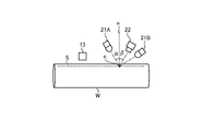
- the position detection device and the position detection method of the seam portion and the heating portion of the welded steel pipe according to the embodiment of the present invention will be described with reference to FIG.
- the position detecting device 2 the position of the seam portion S of the welded steel pipe W and the heating portion generated by the aiming and heating of the seam portion S by the annealer heater 13 during or after heating by the annealer heater 13 The position is detected (position detection process).
- the positions of the seam portion S and the heating portion are both positions on the surface of the welded steel pipe W.
- the position detection device 2 may be installed behind any one of the annealer heaters 13.
- the position detection device 2 includes a light source 21, an image pickup device 22, an image processing device 23, and a display device 24. Further, the position detecting device 2 measures the position of the seam portion S and the position of the heating portion on the surface of the welded steel pipe W from the outside of the welded steel pipe W. Since this position detection step is performed during or after heating by the Annealer heater 13, it is performed during the heating step. In other words, the position detection step is included in the heating step.
- the light source 21 is arranged on the outside of the welded steel pipe W, and irradiates the seam portion S and the heating portion of the welded steel pipe W with light in the first wavelength range.
- the first wavelength range is a wavelength range that does not interfere with the second wavelength range described later.
- the temperature heated by the annealer heater 13 is about 1100 ° C. at the maximum, and as the first wavelength range, for example, the wavelength range of 550 nm or less is self-luminous at 1100 ° C. and has almost no sensitivity. It is preferable because it is not affected by.
- Particularly preferred is the range of 450 nm to 550 nm, which is generally the wavelength range of the blue channel and the green channel of a color camera.
- the light source 21 specifically, it is preferable to use a blue light source or a green light source.
- the LED light source may be used as the blue light source or the green light source described here.
- a filter and a film that transmit only blue or green may be used for a wide band light source such as a metal halide light source, a xenon light source, or a halogen light source.
- a light source capable of irradiating the corresponding portion may be used by placing an optical element having a property of diffusing light rays such as a diffuser plate in front of a laser light source having a wavelength of blue or green.
- the image pickup device 22 is arranged on the outside of the welded steel pipe W and images the seam portion S and the heating portion of the welded steel pipe W irradiated with light by the light source 21.
- the imaging region to be imaged here does not have to be exactly only the seam portion S and the heating portion, and may be a wider region as long as the seam portion S and the heating portion to be measured are included. However, if it is too wide, the area not used for actual measurement increases, and the number of elements of the camera is finite, so that the resolution per pixel is lowered. If it is too narrow, the target heating portion and seam portion S will be out of the visual field region due to fluctuations in the heating portion and seam portion S and changes in the steel pipe diameter, making measurement impossible.
- the imaging range is as high as possible within the range in which the heating portion and the seam portion S can be stably imaged.
- the image pickup apparatus 22 has a plurality of different channels, and has at least a first channel and a second channel.
- the first channel is a channel capable of receiving the reflected light in the first wavelength range irradiated by the light source 21.
- the second channel is a channel capable of receiving the reflected light in the second wavelength region corresponding to the synchrotron radiation generated by the red heat of the seam portion S of the welded steel pipe W. Therefore, as the second wavelength range, for example, a wavelength range of 600 nm or more is preferable. In particular, the range of 600 nm to 1000 nm is more preferable because it is within the sensitivity range of a Si element that is usually inexpensively available.
- an image pickup device including a first channel capable of receiving the first wavelength range described above and a second channel capable of receiving the second wavelength range is used.
- the image pickup apparatus 22 for example, it is preferable to use a color camera having a red channel, a blue channel, and a green channel.
- the first channel corresponds to the blue channel and the green channel
- the second channel corresponds to the red channel.
- the heating temperature of annealing in the heating step or the like is, for example, 800 to 1100 ° C., and the light receiving sensitivity of the blue channel (for example, light in the wavelength band of around 450 nm) to the synchrotron radiation due to red heat is almost zero.
- the red channel for example, light in a wavelength band of around 650 nm
- the light source 21 described above a blue light source having a wavelength range that is the light receiving sensitivity of the blue channel is used, and a color camera is used as the image pickup device 22. Then, the light source 21 irradiates the heated and red-hot seam portion S on the target welded steel pipe W, and the image pickup device 22 images the seam portion S and / or the vicinity of the seam portion S irradiated by the light source 21. As a result, in the optically aligned state, the red channel can receive only the synchrotron radiation due to red heat, and the blue channel can receive only the reflected light of the blue light source.
- the reflected image of the seam portion S is optically aligned with the radiated image of red heat due to heating. It is possible to acquire it in the state.
- the "reflected image” refers to an image in which the light of the light source 21 is reflected by the seam portion S.
- the "radiant image” indicates an image generated by synchrotron radiation from the heating portion generated by aiming and heating the seam portion S.
- the first channel can have one or more channels.
- the second channel can have one or more channels. Further, when the first channel and the second channel each have a plurality of channels, each channel may have sensitivity to a different wavelength range, or may have sensitivity to the same wavelength range. You may.
- the image pickup apparatus 22 may have a two-dimensional field of view, or may have a one-dimensional field of view. When the image pickup apparatus 22 has a one-dimensional field of view, it is necessary to have a field of view in the circumferential direction of the welded steel pipe W.
- the description will be made on the premise that a blue light source is used as the light source 21 and a color camera is used as the image pickup device 22.
- a combination other than the above can be realized as long as the wavelength range of the synchrotron radiation due to red heat and the wavelength range of the light radiated to the target welded steel pipe W can be separated.
- the blue light source 21A and the green light source 21B are arranged in the pipe axis direction of the welded steel pipe W.
- the blue light source 21A can be arranged with respect to the seam portion S and the heating portion so as to have a specular reflection condition
- the green light source 21B can be arranged so as to have a diffuse reflection condition.
- the blue light source 21A and the green light source 21B are arranged at positions symmetrical with respect to the seam portion S in the circumferential direction of the welded steel pipe W, and light is emitted from two directions. May be irradiated. By doing so, even if the seam portion S has irregularities, the direction of the shadow is opposite because the irradiation directions are different between the blue light source 21A and the green light source 21B, and the seam portion S is detected accurately by image processing. It becomes possible. Further, the positional relationship between the blue light source 21A and the green light source 21B in FIGS. 3 and 4 may be interchanged with each other. As described above, by using two sets of optical systems, the detection accuracy of the seam portion S can be improved.
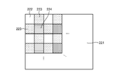
- Bayer method There are mainly Bayer method and prism method as types of color cameras.
- filters of each color red filter 222, green filter 223, blue filter 224.
- the image is separated into the images of each channel in that, the pixel value is obtained only for the pixel in which the filter of each color exists in each channel, and the others are in a state of toothlessness. Therefore, by complementing the pixel values of filters of other colors by upsampling processing, it is possible to generate images for three channels.
- the Bayer method can be realized with a simple configuration, it does not have the resolution of the obtained image, and each channel is also characterized in that the position shifts according to the element size order.
- the prism method as shown in FIG. 6, three image pickup elements 221 for red, green, and blue are prepared, and the colors are separated while being precisely aligned by the prism 225.
- the prism 225 having such a function is called a "die clock prism".
- the prism method does not require upsampling like the Bayer method, and can obtain the position accuracy between each channel with an accuracy of subpixel or less, so it has the feature that higher measurement accuracy can be obtained compared to the Bayer method. be.
- 7A and 7B are images before and after annealing of the seam portion S, where (a) is an image taken under normal reflection conditions before heating, (b) is an image taken under normal reflection conditions after heating, and (c) is before heating.
- the image taken under the diffuse reflection condition, and (d) is the image taken under the diffuse reflection condition after heating.
- the seam portion S immediately after cutting the bead portion B has a very high mirror surface property.
- an oxide film black skin oxide film
- the amount of the oxide film adhered increases, and the surface roughness increases according to the amount of the oxide film adhered.
- the mirror property of the seam portion S decreases and the diffusivity increases. go.
- the seam portion S appears brighter than the other portions, as shown in (a) of FIG. 7, for example, in a state where the mirror surface before heating is high.
- the mirror property is lowered and the diffusivity is increased due to the adhesion of the oxide film. Therefore, for example, as shown in FIG. It looks darker than the part of.
- the difference in brightness before and after heating is large, so that the appearance of the seam portion S is also significantly different.
- FIG. 8A schematically shows the relationship between the amount of the oxide film adhered and the specular reflection brightness.
- the solid line is the change in the specular brightness of the seam portion S
- the broken line is the change in the specular reflection brightness other than the seam portion S
- the horizontal axis is the amount of the oxide film adhered to the seam portion S
- the vertical axis is the positive. It shows the reflected brightness.
- FIG. 8B schematically shows the relationship between the amount of the oxide film adhered and the diffuse reflection luminance.
- FIG. 8A the solid line is the change in the specular brightness of the seam portion S
- the broken line is the change in the specular reflection brightness other than the seam portion S
- the horizontal axis is the amount of the oxide film adhered to the seam portion S
- the vertical axis is the positive. It shows the reflected brightness.
- FIG. 8B schematically shows the relationship between the amount of the oxide film adhered and the diffuse reflection luminance.
- the solid line is the change in the diffuse reflection brightness of the seam portion S
- the broken line is the change in the diffuse reflection brightness other than the seam portion S
- the horizontal axis is the amount of the oxide film adhered to the seam portion S
- the vertical axis is the diffusion. It shows the reflected brightness.
- the positions of the horizontal axes are substantially aligned so that the positions of the horizontal axes are the same for the same amount of adhesion.
- the vertical alternate long and short dash line indicates a certain point in time when the oxide film of the seam portion S has the same amount of adhesion.
- the seam portion S can be detected from the diffuse reflection luminance. That is, if the specular reflection information and the diffuse reflection information are combined, the detection of the seam portion S becomes more reliable, which is more preferable.
- FIG. 9 shows an example of a flowchart for detecting the position of the seam portion S by combining the specular reflection information and the diffuse reflection information.
- the seam portion S and the portion other than the seam portion S are compared to determine whether or not there is a difference in the specular reflection brightness (step S1).
- the seam portion S is calculated by threshold processing or the like using the difference in brightness of the specular image (step S2).
- the seam portion S is calculated by utilizing the fact that the seam portion S looks bright or dark at the brightness value of diffuse reflection (step).
- FIG. 9 is an example of a flowchart for stably detecting the seam portion S.
- the seam portion S may be directly extracted from the specular reflection image and the diffuse reflection image by using four rules calculation, threshold value processing, AND processing, OR processing, or a combination of these processes. ..
- the light source 21 blue light source in the present embodiment
- the image pickup device 22 color camera in the present embodiment
- the measurement points c including the portion S are seams. It is preferable to arrange the measurement points c including the portion S so as to have a specular reflection condition. For example, when arranging in the tube axis direction, it is preferable to install the light source 21 and the image pickup device 22 as shown in FIG. In this case, the light source 21 and the image pickup device 22 are subjected to the light irradiation angle ⁇ by the light source 21 and the light reception angle by the image pickup device 22 with respect to the normal vector n of the measurement point c including the seam portion S of the welded steel tube W.
- the seam portion S can be accurately detected before and after annealing.
- the light source 21 and the image pickup apparatus 22 may be arranged other than the above arrangement as long as the seam portion S can be appropriately detected.
- the description of the configuration of the position detection device 2 will be returned.
- the image processing device 23 processes the image captured by the image pickup device 22 by a well-known image processing technique, and detects the position of the seam portion S and the position of the heating portion (the positional relationship between the two) of the welded steel pipe W, respectively. Further, the image processing device 23 may detect (calculate) the amount of deviation of the position of the heating portion with respect to the position of the seam portion S in addition to the detected positions of the seam portion S and the heating portion.
- the above-mentioned "devioned "deviation amount” specifically indicates the deviation amount in the circumferential direction of the welded steel pipe W.
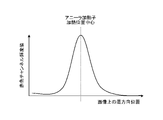
- the position of the heating portion is high brightness as shown in the luminance profile shown in FIG. Therefore, the position of the heating portion can be detected by calculating the position where the brightness becomes high.
- the position of the heating portion can be detected based on, for example, the position of the center of gravity in the width direction, the position where the maximum brightness is obtained, the center position after binarization by the threshold processing, the position of the center of gravity, and the like.
- the specular reflection image of the welded steel pipe W obtained in the blue channel of the image pickup apparatus 22 looks bright when the amount of the oxide film on the surface is small (see (a) in FIG. 7), and the oxide film is sufficiently adhered. It looks dark when it is present (see (b) in the figure). Therefore, the position of the brightened portion and the position of the darkened portion are calculated by the same concept as in the case of the red channel.
- pretreatment such as rotating the image. Further, it is preferable to reduce noise by pretreatment such as removing high frequency components by a frequency filter or the like, calculating integration / averaging / median processing in the pipe axis direction of the welded steel pipe W.
- the seam portion S can be determined by visually observing the image, for example, an image of the heating portion and an image of the seam portion S. May be visually displayed to the operator through the display device 24.
- the display device 24 provides guidance to the operator by displaying the processing result of the image processing device 23.
- the display device 24 can display, for example, the amount of deviation of the position of the heating portion with respect to the position of the seam portion S of the welded steel pipe W detected by the image processing device 23 as a numerical value. Further, the display device 24 may display the position of the seam portion S and the position of the heating portion as an image.
- the image received by the blue channel of the image pickup apparatus 22 and the image received by the red channel may be superimposed and displayed.
- an image showing the position of the seam portion S and an image showing the position of the heating portion may be displayed side by side in the transport direction of the welded steel pipe W.
- the position of the heating portion estimated from the position of the annealer heater 13 is displayed by superimposing it on the seam portion S. You may.
- the position detecting device 2 may be provided with a notification means for notifying by an alarm when there is a distance equal to or greater than a predetermined threshold value between the position of the seam portion S and the position of the heating portion. Further, the position detection device 2 may include a recording means for accumulating the images processed by the image processing device 23 and recording the transition of the heating state.
- the position detection results of the seam portion S and the heating portion of the welded steel pipe W are displayed on the display device 24.
- the position of the annealer heater 13 may be controlled based on the amount of deviation between the positions of the seam portion S and the heating portion detected by the image processing device 23.
- the position detection device 2A shown in the figure includes a heater position control device 25 in addition to the configuration of the position detection device 2 shown in FIG.
- the heater position control device 25 controls the position of the annealer heater 13 based on the amount of deviation of the position of the heating unit with respect to the position of the seam portion S detected by the image processing device 23 of the position detection device 2A. That is, the heater position control device 25 moves the position of the annealing heater 13 in the circumferential direction of the welded steel pipe W so that the heating portion coincides with the seam portion S. In this way, by controlling the position of the annealing heater 13 based on the amount of deviation of the position of the heating portion with respect to the position of the seam portion S, it is possible to heat the seam portion S with high accuracy.
- the positions of the annealer heaters 13 before and / or after the position detection device 2A according to the present invention can be controlled.
- the position of the annealing heater 13 in front of the position detecting device 2A it becomes feedback and stable control of the heating process becomes possible.
- the position of the annealer heater 13 behind the position detection device 2A it becomes feedforward, and the control becomes more responsive, and the seam portion S heated by the displacement is also from the position detection device 2A. Later, it will be heated correctly.
- the position of the annealing heater 13 in front of and behind the position detecting device 2A is controlled, and the advantages of both feedback and feedforward can be obtained.
- the most preferable is to control the positions of all the annealing heaters 13 before and after the position detecting device 2A, so that the effect in the target heating step can be obtained more reliably.
- a plurality of position detecting devices 2A may be installed before and after each annealing heater 13. preferable. By arranging in this way, it becomes possible to grasp the positional relationship between the heating portion and the seam portion S for each Annealer heater 13, and even if twisting occurs, the position control performance is improved. It is preferable to install more position detection devices 2A, but the most preferable is to grasp the positional relationship between the heating part and the seam part S before and after all the annealing heaters 13, and the influence of the twist is completely affected. Can be excluded from.
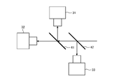
- Modification 2 of the present invention will be described.
- the second modification as shown in FIG. 14, instead of the color camera, two cameras 31 and 32 having the same optical characteristics and a beam splitter 41 are used.
- a prism may be used instead of the beam splitter 41. Then, the two cameras 31 and 32 are aligned with each other by using the beam splitter 41, and the target fields of view are adjusted to be the same.
- the optical characteristics described here refer to the field of view and resolution.
- a filter that transmits only the first wavelength region and a filter that transmits only the second wavelength region are installed. This makes it possible to obtain a reflected image and a radiated image in a aligned state, and it is possible to obtain the same effect as when a color camera is used.
- image processing is performed. May be aligned by.
- a die clock mirror having a characteristic of controlling the reflection direction or transmitting the light depending on the wavelength range may be used.
- Modification 3 of the present invention will be described.
- a color camera 34 and a half mirror 43 are used.
- a coaxial epi-illumination optical system as shown in FIG. 16 may be adopted. That is, the surface of the welded steel pipe W is irradiated with light rays in the first wavelength range through the half mirror 43, the reflected light is transmitted through the half mirror 43, and is received by the color camera 34. Further, since the light in the second wavelength range can be received through the half mirror 43, it is possible to receive the reflected light, receive the self-luminous light, and irradiate the same coaxially, which saves space. You can expect it.
- the quality control method of the welded steel pipe W controls the quality of the welded steel pipe W based on the amount of deviation of the position of the heating portion with respect to the position of the seam portion S detected by the position detecting devices 2 and 2A.
- the quality control method for example, when the above-mentioned deviation amount is equal to or higher than a predetermined threshold value, an inspection step is carried out to inspect whether the quality (for example, toughness, etc.) of the welded steel pipe W meets the predetermined required specifications. do. Then, based on the result of the inspection process, it is decided whether to reuse the welded steel pipe W as a grade drop or to dispose of it as an NG product.
- the welded steel pipe W having excellent quality.
- the welded steel tube W is imaged by an image pickup device 22 having a channel for receiving the reflected light of the light radiated from the light source 21 to the seam portion S and a channel for receiving the synchrotron radiation due to the red heat of the heating portion. It can be a costly and simple configuration. In addition, the positions of the seam portion and the heating portion can be detected with high accuracy.
- the position detection device for the seam portion and the heating portion of the welded steel pipe, the manufacturing equipment for the welded steel pipe, the position detection method for the seam portion and the heating portion of the welded steel pipe, the manufacturing method for the welded steel pipe, and the quality control method for the welded steel pipe according to the embodiment. According to the report, the following effects are also achieved. That is, it becomes possible to visualize and automate the measures for preventing the positional deviation of the positional relationship between the seam portion S and the heating portion, which conventionally depended on the visual inspection of the actual object by the operator.
- the position detection device for the seam portion and the heating portion of the welded steel pipe the manufacturing equipment for the welded steel pipe, the position detection method for the seam portion and the heating portion of the welded steel pipe, the manufacturing method for the welded steel pipe, and the quality control method for the welded steel pipe according to the present invention.
- the gist of the present invention is not limited to these statements, and must be broadly interpreted based on the statements of the claims. Needless to say, various changes, modifications, etc. based on these descriptions are also included in the gist of the present invention.
- Example ⁇ Examples of the present invention will be described.
- the same position detection device as in FIG. 2 was constructed, and the positions of the seam portion and the heating portion were detected.
- a 640 ⁇ 480 pixel color camera was used as the image pickup apparatus, and a spot light source capable of irradiating only blue light was used as the light source.
- the arrangement of the image pickup device and the light source was set to a specular reflection condition, and the irradiation angle of light was set to 5 degrees.
- FIG. 17 shows the result of calculating the positions of the seam portion and the thermal portion by the center of gravity processing from the obtained image. As shown in the figure, it can be seen that the heating portion can accurately follow the seam portion.
- a Bayer type color camera is used as the image pickup device, but a prism type color camera may be used.
- the image was taken under the specular reflection condition, but if the difference between the seam portion and the portion other than the seam portion can be detected as a feature of the image, the image may be taken under the diffuse reflection condition, or FIG. And the image may be taken using the optical system shown in FIG.
Landscapes
- Engineering & Computer Science (AREA)
- Mechanical Engineering (AREA)
- Chemical & Material Sciences (AREA)
- Physics & Mathematics (AREA)
- Thermal Sciences (AREA)
- Crystallography & Structural Chemistry (AREA)
- Materials Engineering (AREA)
- Metallurgy (AREA)
- Organic Chemistry (AREA)
- Quality & Reliability (AREA)
- General Physics & Mathematics (AREA)
- Manufacturing & Machinery (AREA)
- Length Measuring Devices By Optical Means (AREA)
Priority Applications (6)
| Application Number | Priority Date | Filing Date | Title |
|---|---|---|---|
| KR1020237017728A KR20230096051A (ko) | 2020-12-03 | 2021-09-08 | 용접 강관의 심부 및 가열부의 위치 검출 장치, 용접 강관의 제조 설비, 용접 강관의 심부 및 가열부의 위치 검출 방법, 용접 강관의 제조 방법 및 용접 강관의 품질 관리 방법 |
| CA3199400A CA3199400A1 (en) | 2020-12-03 | 2021-09-08 | Position detection apparatus for seam portion and heating portion of welded steel pipe, manufacturing equipment for welded steel pipe, position detection method for seam portion and heating portion of welded steel pipe, manufacturing method for welded steel pipe, and quality control method for welded steel pip |
| US18/037,178 US12358081B2 (en) | 2020-12-03 | 2021-09-08 | Position detection apparatus for seam portion and heating portion of welded steel pipe, manufacturing equipment for welded steel pipe, position detection method for seam portion and heating portion of welded steel pipe, manufacturing method for welded steel pipe, and quality control method for welded steel pipe |
| EP21900271.4A EP4257260B1 (en) | 2020-12-03 | 2021-09-08 | Position detection device for seam portion and heated portion in welded steel pipe, manufacturing equippment of welded steel pipe, position detection method for seam portion and heated portion in welded steel pipe, manufacturing method of welded steel pipe, and quality control method for welded steel pipe |
| CN202180081081.0A CN116547085A (zh) | 2020-12-03 | 2021-09-08 | 焊接钢管的接缝部以及加热部的位置检测装置、焊接钢管的制造设备、焊接钢管的接缝部以及加热部的位置检测方法、焊接钢管的制造方法以及焊接钢管的品质管理方法 |
| JP2021570286A JP7151912B1 (ja) | 2020-12-03 | 2021-09-08 | 溶接鋼管のシーム部および加熱部の位置検出装置、溶接鋼管の製造設備、溶接鋼管のシーム部および加熱部の位置検出方法、溶接鋼管の製造方法および溶接鋼管の品質管理方法 |
Applications Claiming Priority (2)
| Application Number | Priority Date | Filing Date | Title |
|---|---|---|---|
| JP2020-201226 | 2020-12-03 | ||
| JP2020201226 | 2020-12-03 |
Publications (1)
| Publication Number | Publication Date |
|---|---|
| WO2022118515A1 true WO2022118515A1 (ja) | 2022-06-09 |
Family
ID=81854109
Family Applications (1)
| Application Number | Title | Priority Date | Filing Date |
|---|---|---|---|
| PCT/JP2021/033008 Ceased WO2022118515A1 (ja) | 2020-12-03 | 2021-09-08 | 溶接鋼管のシーム部および加熱部の位置検出装置、溶接鋼管の製造設備、溶接鋼管のシーム部および加熱部の位置検出方法、溶接鋼管の製造方法および溶接鋼管の品質管理方法 |
Country Status (7)
| Country | Link |
|---|---|
| US (1) | US12358081B2 (https=) |
| EP (1) | EP4257260B1 (https=) |
| JP (1) | JP7151912B1 (https=) |
| KR (1) | KR20230096051A (https=) |
| CN (1) | CN116547085A (https=) |
| CA (1) | CA3199400A1 (https=) |
| WO (1) | WO2022118515A1 (https=) |
Families Citing this family (2)
| Publication number | Priority date | Publication date | Assignee | Title |
|---|---|---|---|---|
| JP2024063549A (ja) * | 2022-10-26 | 2024-05-13 | Jfeスチール株式会社 | 溶接鋼管の熱処理設備、溶接鋼管の製造設備、溶接鋼管の熱処理方法および溶接鋼管の製造方法 |
| JP7755219B1 (ja) * | 2024-03-26 | 2025-10-16 | 日本製鉄株式会社 | 電縫管の製造方法及び製造装置、並びに監視装置 |
Citations (9)
| Publication number | Priority date | Publication date | Assignee | Title |
|---|---|---|---|---|
| JPS5225687A (en) | 1975-08-21 | 1977-02-25 | Nippon Steel Corp | Method of detecting weld zones of seamwelded steel pipes |
| JPS5633542A (en) | 1979-08-27 | 1981-04-04 | Nippon Steel Corp | Detecting device for seam of electro-unite tube |
| JPS59108903A (ja) | 1982-12-14 | 1984-06-23 | Kawasaki Steel Corp | 電縫管のシ−ム位置検出方法 |
| JPS6242004A (ja) | 1985-08-19 | 1987-02-24 | Kawasaki Steel Corp | 電縫管のシ−ム位置検出装置 |
| JPH05240844A (ja) | 1991-11-29 | 1993-09-21 | Nippon Steel Corp | 電縫管溶接部探傷装置の倣い方法 |
| JPH10170228A (ja) | 1996-12-13 | 1998-06-26 | Sumitomo Metal Ind Ltd | 電縫管シーム部検出装置及び方法 |
| JPH10193155A (ja) * | 1997-01-06 | 1998-07-28 | Sumitomo Metal Ind Ltd | 溶接におけるずれ量計測方法及び装置並びにシーム倣い制御方法及び装置 |
| JP2007120985A (ja) * | 2005-10-25 | 2007-05-17 | Jfe Steel Kk | 電縫管のシームアニーラ位置ずれ検出方法、装置、及び、シームアニーラの加熱子位置制御方法、装置 |
| WO2018092461A1 (ja) * | 2016-11-21 | 2018-05-24 | 株式会社中田製作所 | 溶接管製造装置および溶接管製造方法 |
Family Cites Families (30)
| Publication number | Priority date | Publication date | Assignee | Title |
|---|---|---|---|---|
| DE19852302A1 (de) * | 1998-11-12 | 2000-05-25 | Fraunhofer Ges Forschung | Verfahren und Vorrichtung zum Bearbeiten von Werkstücken mit Hochenergiestrahlung |
| JP3603843B2 (ja) * | 2001-02-23 | 2004-12-22 | 日産自動車株式会社 | レーザー溶接部の品質モニタリング方法およびその装置 |
| JP4591201B2 (ja) * | 2004-09-29 | 2010-12-01 | Jfeスチール株式会社 | 電縫管のシーム位置検出方法、装置、及び、電縫管の製造方法、設備 |
| DE102007000981B4 (de) * | 2007-02-22 | 2020-07-30 | Vistec Semiconductor Systems Gmbh | Vorrichtung und Verfahren zum Vermessen von Strukturen auf einer Maske und zur Berechnung der aus den Strukturen resultierenden Strukturen in einem Photoresist |
| JP5252026B2 (ja) * | 2011-05-10 | 2013-07-31 | パナソニック株式会社 | レーザ溶接装置及びレーザ溶接方法 |
| KR101476594B1 (ko) * | 2011-11-09 | 2014-12-24 | 신닛테츠스미킨 카부시키카이샤 | 전봉 용접 조업의 감시 장치, 방법 및 프로그램을 저장하는 컴퓨터 판독가능한 기억 매체 |
| JP5842851B2 (ja) * | 2013-03-29 | 2016-01-13 | トヨタ自動車株式会社 | 溶接部の検査装置とその検査方法 |
| JP6232734B2 (ja) * | 2013-04-26 | 2017-11-22 | 株式会社ジェイテクト | 光学非破壊検査装置及び光学非破壊検査方法 |
| WO2015007322A1 (en) * | 2013-07-18 | 2015-01-22 | Toyota Motor Europe Nv/Sa | Systems and methods for assuring and improving process quality |
| DE102013218421A1 (de) * | 2013-09-13 | 2015-04-02 | Trumpf Werkzeugmaschinen Gmbh + Co. Kg | Vorrichtung und Verfahren zur Überwachung, insbesondere zur Regelung, eines Schneidprozesses |
| DE102013022085A1 (de) * | 2013-12-23 | 2015-06-25 | Fraunhofer-Gesellschaft zur Förderung der angewandten Forschung e.V. | Verfahren und Vorrichtung zur Überwachung und Regelung der Bearbeitungsbahn bei einem Laser-Fügeprozess |
| US10262412B2 (en) * | 2014-04-03 | 2019-04-16 | Nippon Steel & Sumitomo Metal Corporation | Welded state monitoring system and welded state monitoring method |
| US20160193680A1 (en) * | 2015-01-07 | 2016-07-07 | Illinois Tool Works Inc. | Automated welding translation platform |
| US10479020B2 (en) * | 2017-08-01 | 2019-11-19 | Sigma Labs, Inc. | Systems and methods for measuring radiated thermal energy during an additive manufacturing operation |
| JP6579400B2 (ja) * | 2017-10-26 | 2019-09-25 | パナソニックIpマネジメント株式会社 | レーザ溶接装置及びレーザ溶接方法 |
| TWI776990B (zh) * | 2017-11-14 | 2022-09-11 | 日商大日本印刷股份有限公司 | 用以製造蒸鍍罩之金屬板及金屬板之製造方法、以及蒸鍍罩及蒸鍍罩之製造方法 |
| WO2019110114A1 (en) * | 2017-12-07 | 2019-06-13 | Bystronic Laser Ag | Device for monitoring beam treatment of a workpiece and use thereof, device for beam treatment of a workpiece and use thereof, method for monitoring beam treatment of a workpiece, method for beam treatment of a workpiece |
| WO2019142350A1 (ja) * | 2018-01-22 | 2019-07-25 | 日本製鉄株式会社 | 溶接操業監視システムおよび溶接操業監視方法 |
| WO2019159659A1 (ja) * | 2018-02-16 | 2019-08-22 | パナソニックIpマネジメント株式会社 | レーザ溶接装置及びレーザ溶接方法 |
| CN111093887B (zh) * | 2018-02-16 | 2022-06-28 | 松下知识产权经营株式会社 | 激光焊接装置及激光焊接方法 |
| DE112019000498B4 (de) * | 2018-02-21 | 2022-06-09 | Sigma Labs, Inc. | Additives Fertigungsverfahren |
| CN111971143B (zh) * | 2018-04-13 | 2022-11-11 | 松下知识产权经营株式会社 | 激光焊接装置 |
| MX2021007281A (es) * | 2018-12-20 | 2021-07-15 | Etxetar Sa | Metodo de procesamiento de un objeto con un haz de luz, y sistema de procesamiento. |
| CN111347157B (zh) * | 2018-12-21 | 2023-04-28 | 松下知识产权经营株式会社 | 激光焊接装置以及激光焊接方法 |
| DE102019103734A1 (de) * | 2019-02-14 | 2020-08-20 | Precitec Gmbh & Co. Kg | Laserbearbeitungssystem zur Bearbeitung eines Werkstücks mittels eines Laserstrahls und Verfahren zum Steuern eines Laserbearbeitungssystems |
| JP7247876B2 (ja) * | 2019-12-10 | 2023-03-29 | トヨタ自動車株式会社 | 溶着ビード切削装置および溶着ビード切削方法 |
| WO2021177436A1 (ja) * | 2020-03-05 | 2021-09-10 | パナソニックIpマネジメント株式会社 | ビード外観検査装置、ビード外観検査方法、プログラムおよびビード外観検査システム |
| JP7353221B2 (ja) * | 2020-03-09 | 2023-09-29 | 株式会社アマダ | レーザ溶接モニタリング装置及びレーザ溶接モニタリング方法 |
| CN112091480B (zh) * | 2020-08-06 | 2022-02-11 | 苏州实创德光电科技有限公司 | 用于直缝管轴向焊缝识别的辅助内照明系统及焊接方法 |
| WO2022181061A1 (ja) * | 2021-02-25 | 2022-09-01 | パナソニックIpマネジメント株式会社 | 推定モデル生成装置および加工状態推定装置 |
-
2021
- 2021-09-08 KR KR1020237017728A patent/KR20230096051A/ko active Pending
- 2021-09-08 JP JP2021570286A patent/JP7151912B1/ja active Active
- 2021-09-08 WO PCT/JP2021/033008 patent/WO2022118515A1/ja not_active Ceased
- 2021-09-08 CN CN202180081081.0A patent/CN116547085A/zh active Pending
- 2021-09-08 US US18/037,178 patent/US12358081B2/en active Active
- 2021-09-08 CA CA3199400A patent/CA3199400A1/en active Pending
- 2021-09-08 EP EP21900271.4A patent/EP4257260B1/en active Active
Patent Citations (9)
| Publication number | Priority date | Publication date | Assignee | Title |
|---|---|---|---|---|
| JPS5225687A (en) | 1975-08-21 | 1977-02-25 | Nippon Steel Corp | Method of detecting weld zones of seamwelded steel pipes |
| JPS5633542A (en) | 1979-08-27 | 1981-04-04 | Nippon Steel Corp | Detecting device for seam of electro-unite tube |
| JPS59108903A (ja) | 1982-12-14 | 1984-06-23 | Kawasaki Steel Corp | 電縫管のシ−ム位置検出方法 |
| JPS6242004A (ja) | 1985-08-19 | 1987-02-24 | Kawasaki Steel Corp | 電縫管のシ−ム位置検出装置 |
| JPH05240844A (ja) | 1991-11-29 | 1993-09-21 | Nippon Steel Corp | 電縫管溶接部探傷装置の倣い方法 |
| JPH10170228A (ja) | 1996-12-13 | 1998-06-26 | Sumitomo Metal Ind Ltd | 電縫管シーム部検出装置及び方法 |
| JPH10193155A (ja) * | 1997-01-06 | 1998-07-28 | Sumitomo Metal Ind Ltd | 溶接におけるずれ量計測方法及び装置並びにシーム倣い制御方法及び装置 |
| JP2007120985A (ja) * | 2005-10-25 | 2007-05-17 | Jfe Steel Kk | 電縫管のシームアニーラ位置ずれ検出方法、装置、及び、シームアニーラの加熱子位置制御方法、装置 |
| WO2018092461A1 (ja) * | 2016-11-21 | 2018-05-24 | 株式会社中田製作所 | 溶接管製造装置および溶接管製造方法 |
Non-Patent Citations (1)
| Title |
|---|
| See also references of EP4257260A4 |
Also Published As
| Publication number | Publication date |
|---|---|
| KR20230096051A (ko) | 2023-06-29 |
| EP4257260A4 (en) | 2024-05-15 |
| JP7151912B1 (ja) | 2022-10-12 |
| CA3199400A1 (en) | 2022-06-09 |
| JPWO2022118515A1 (https=) | 2022-06-09 |
| EP4257260A1 (en) | 2023-10-11 |
| US12358081B2 (en) | 2025-07-15 |
| CN116547085A (zh) | 2023-08-04 |
| US20240017358A1 (en) | 2024-01-18 |
| EP4257260B1 (en) | 2026-02-11 |
Similar Documents
| Publication | Publication Date | Title |
|---|---|---|
| JP7318817B2 (ja) | 溶接鋼管のシーム部および加熱部の位置検出装置、溶接鋼管の製造設備、溶接鋼管のシーム部および加熱部の位置検出方法、溶接鋼管の製造方法および溶接鋼管の品質管理方法 | |
| KR100891842B1 (ko) | 원형 선재 광학결함 검출장치 및 방법 | |
| EP3168613B1 (en) | Ultrasonic flaw detection device and ultrasonic flaw detection method | |
| CN102990224A (zh) | 用于在激光焊接过程期间检查焊缝质量的方法 | |
| JP7151912B1 (ja) | 溶接鋼管のシーム部および加熱部の位置検出装置、溶接鋼管の製造設備、溶接鋼管のシーム部および加熱部の位置検出方法、溶接鋼管の製造方法および溶接鋼管の品質管理方法 | |
| WO2003093761A1 (fr) | Procede et instrument de mesure de la forme de coupe du manchon de verre d'un tube electrique soude | |
| CN107081503A (zh) | 一种弧焊质量的红外无损检测装置及其红外无损检测方法 | |
| WO2013069748A1 (ja) | 電縫溶接操業の監視装置、方法、プログラム、及び記憶媒体 | |
| JP2018020356A (ja) | 電縫鋼管の溶接工程の溶接監視方法及び溶接監視装置 | |
| JP3230447B2 (ja) | 電縫管シーム部検出装置及び方法 | |
| JP4591201B2 (ja) | 電縫管のシーム位置検出方法、装置、及び、電縫管の製造方法、設備 | |
| JP2020069518A (ja) | 溶接モニタリング装置および溶接モニタリング方法 | |
| JP2007120985A (ja) | 電縫管のシームアニーラ位置ずれ検出方法、装置、及び、シームアニーラの加熱子位置制御方法、装置 | |
| JP7754312B2 (ja) | シーム位置検出方法、溶接鋼管の製造方法、溶接鋼管の品質管理方法、シーム位置検出装置および溶接鋼管の製造設備 | |
| US12350753B2 (en) | Method for monitoring welding of electric resistance welded steel pipe, method for manufacturing electric resistance welded steel pipe, device for monitoring welding of electric resistance welded steel pipe, and device for manufacturing electric resistance welded steel pipe | |
| JP2024063549A (ja) | 溶接鋼管の熱処理設備、溶接鋼管の製造設備、溶接鋼管の熱処理方法および溶接鋼管の製造方法 | |
| JP2004109023A (ja) | 鋼材表面の測温方法及び測温装置 | |
| CA3290341A1 (en) | Seam position detection method, manufacturing method of welded steel pipe, quality control method of welded steel pipe, seam position detection apparatus, and manufacturing equipment of welded steel pipe | |
| JP2008175577A (ja) | 電縫溶接管溶接部監視方法及び監視装置並びに電縫溶接管の製造方法 | |
| JP6054618B2 (ja) | 溶接鋼管の製造装置 | |
| JPH0577062A (ja) | 熱間電縫管溶接部の監視方法とその装置 | |
| JPH01113175A (ja) | 溶接異常検出方法 | |
| JPS5948937B2 (ja) | 溶接部処理装置 |
Legal Events
| Date | Code | Title | Description |
|---|---|---|---|
| ENP | Entry into the national phase |
Ref document number: 2021570286 Country of ref document: JP Kind code of ref document: A |
|
| 121 | Ep: the epo has been informed by wipo that ep was designated in this application |
Ref document number: 21900271 Country of ref document: EP Kind code of ref document: A1 |
|
| WWE | Wipo information: entry into national phase |
Ref document number: 18037178 Country of ref document: US |
|
| ENP | Entry into the national phase |
Ref document number: 3199400 Country of ref document: CA |
|
| ENP | Entry into the national phase |
Ref document number: 20237017728 Country of ref document: KR Kind code of ref document: A |
|
| WWE | Wipo information: entry into national phase |
Ref document number: 202180081081.0 Country of ref document: CN |
|
| NENP | Non-entry into the national phase |
Ref country code: DE |
|
| ENP | Entry into the national phase |
Ref document number: 2021900271 Country of ref document: EP Effective date: 20230703 |
|
| WWG | Wipo information: grant in national office |
Ref document number: 18037178 Country of ref document: US |
|
| WWG | Wipo information: grant in national office |
Ref document number: 2021900271 Country of ref document: EP |