WO2022113201A1 - 消費電力監視装置及びプログラム - Google Patents
消費電力監視装置及びプログラム Download PDFInfo
- Publication number
- WO2022113201A1 WO2022113201A1 PCT/JP2020/043804 JP2020043804W WO2022113201A1 WO 2022113201 A1 WO2022113201 A1 WO 2022113201A1 JP 2020043804 W JP2020043804 W JP 2020043804W WO 2022113201 A1 WO2022113201 A1 WO 2022113201A1
- Authority
- WO
- WIPO (PCT)
- Prior art keywords
- change
- equipment
- degree
- power consumption
- period
- Prior art date
- Legal status (The legal status is an assumption and is not a legal conclusion. Google has not performed a legal analysis and makes no representation as to the accuracy of the status listed.)
- Ceased
Links
Images





Classifications
-
- G—PHYSICS
- G01—MEASURING; TESTING
- G01R—MEASURING ELECTRIC VARIABLES; MEASURING MAGNETIC VARIABLES
- G01R21/00—Arrangements for measuring electric power or power factor
-
- G—PHYSICS
- G01—MEASURING; TESTING
- G01R—MEASURING ELECTRIC VARIABLES; MEASURING MAGNETIC VARIABLES
- G01R21/00—Arrangements for measuring electric power or power factor
- G01R21/133—Arrangements for measuring electric power or power factor by using digital technique
-
- G—PHYSICS
- G06—COMPUTING OR CALCULATING; COUNTING
- G06Q—INFORMATION AND COMMUNICATION TECHNOLOGY [ICT] SPECIALLY ADAPTED FOR ADMINISTRATIVE, COMMERCIAL, FINANCIAL, MANAGERIAL OR SUPERVISORY PURPOSES; SYSTEMS OR METHODS SPECIALLY ADAPTED FOR ADMINISTRATIVE, COMMERCIAL, FINANCIAL, MANAGERIAL OR SUPERVISORY PURPOSES, NOT OTHERWISE PROVIDED FOR
- G06Q50/00—Information and communication technology [ICT] specially adapted for implementation of business processes of specific business sectors, e.g. utilities or tourism
- G06Q50/06—Energy or water supply
-
- H—ELECTRICITY
- H02—GENERATION; CONVERSION OR DISTRIBUTION OF ELECTRIC POWER
- H02J—ELECTRIC POWER NETWORKS; CIRCUIT ARRANGEMENTS OR SYSTEMS FOR SUPPLYING OR DISTRIBUTING ELECTRIC POWER; SYSTEMS FOR STORING ELECTRIC ENERGY
- H02J13/00—Circuit arrangements for providing remote monitoring or remote control of equipment in a power distribution network
-
- H—ELECTRICITY
- H02—GENERATION; CONVERSION OR DISTRIBUTION OF ELECTRIC POWER
- H02J—ELECTRIC POWER NETWORKS; CIRCUIT ARRANGEMENTS OR SYSTEMS FOR SUPPLYING OR DISTRIBUTING ELECTRIC POWER; SYSTEMS FOR STORING ELECTRIC ENERGY
- H02J3/00—Circuit arrangements for AC mains or AC distribution networks
-
- Y—GENERAL TAGGING OF NEW TECHNOLOGICAL DEVELOPMENTS; GENERAL TAGGING OF CROSS-SECTIONAL TECHNOLOGIES SPANNING OVER SEVERAL SECTIONS OF THE IPC; TECHNICAL SUBJECTS COVERED BY FORMER USPC CROSS-REFERENCE ART COLLECTIONS [XRACs] AND DIGESTS
- Y04—INFORMATION OR COMMUNICATION TECHNOLOGIES HAVING AN IMPACT ON OTHER TECHNOLOGY AREAS
- Y04S—SYSTEMS INTEGRATING TECHNOLOGIES RELATED TO POWER NETWORK OPERATION, COMMUNICATION OR INFORMATION TECHNOLOGIES FOR IMPROVING THE ELECTRICAL POWER GENERATION, TRANSMISSION, DISTRIBUTION, MANAGEMENT OR USAGE, i.e. SMART GRIDS
- Y04S10/00—Systems supporting electrical power generation, transmission or distribution
- Y04S10/40—Display of information, e.g. of data or controls
-
- Y—GENERAL TAGGING OF NEW TECHNOLOGICAL DEVELOPMENTS; GENERAL TAGGING OF CROSS-SECTIONAL TECHNOLOGIES SPANNING OVER SEVERAL SECTIONS OF THE IPC; TECHNICAL SUBJECTS COVERED BY FORMER USPC CROSS-REFERENCE ART COLLECTIONS [XRACs] AND DIGESTS
- Y04—INFORMATION OR COMMUNICATION TECHNOLOGIES HAVING AN IMPACT ON OTHER TECHNOLOGY AREAS
- Y04S—SYSTEMS INTEGRATING TECHNOLOGIES RELATED TO POWER NETWORK OPERATION, COMMUNICATION OR INFORMATION TECHNOLOGIES FOR IMPROVING THE ELECTRICAL POWER GENERATION, TRANSMISSION, DISTRIBUTION, MANAGEMENT OR USAGE, i.e. SMART GRIDS
- Y04S10/00—Systems supporting electrical power generation, transmission or distribution
- Y04S10/50—Systems or methods supporting the power network operation or management, involving a certain degree of interaction with the load-side end user applications
Definitions
- the present invention relates to a power consumption monitoring device and a program, particularly to detect changes in power consumption.
- the power consumption for the next year may be predicted and an energy saving control plan may be formulated by referring to the past results of the property, for example, the power consumption for the past year and the equipment operation history.
- the equipment such as a change in the equipment, an update of the equipment, or a change in the operation pattern
- the power consumption or the operation pattern of the equipment may change. Therefore, if such changes are not reflected in the prediction of power consumption, it may not be possible to formulate an energy saving control plan with high accuracy.
- the power consumption of the equipment may also change.
- the prior art in order to recognize the change in the power consumption of each equipment, it is premised that the power consumption of each equipment can be measured, but the equipment cost for the measurement is incurred.
- the power consumption monitoring device generates a predetermined event in each of the reference period as a reference for analyzing the power consumption of the equipment and the target period to be analyzed by referring to the equipment operation history information.
- the equipment obtained from the distribution of the occurrence time of the predetermined event in the target period with respect to the operation pattern of the equipment obtained from the occurrence time extraction means for extracting the time and the distribution of the occurrence time of the predetermined event in the reference period. It has a change degree calculating means for calculating the change degree of the operation pattern of the above, and an output control means for outputting the change degree calculated by the change degree calculation means.
- the predetermined event shall be when the power of the equipment is turned on or off.
- the predetermined event is assumed to be a case where the equipment is an air-conditioning equipment and the setting of the air-conditioning equipment is changed so as to meet the predetermined generation conditions.
- the change degree calculation means calculates KL divergence or JS divergence as the change degree.
- the change degree calculation means calculates the KS test statistic or the Anderson-Darling test statistic as the change degree.
- the change degree calculation means calculates the change degree for each event, weights the calculated change degree of each event, and makes a single change. It calculates the degree.
- a predetermined event occurs in each of the reference period for analyzing the power consumption of the equipment and the target period for the analysis by referring to the equipment operation history information of the computer.
- Occurrence time extraction means for extracting time, equipment obtained from the distribution of the occurrence time of the predetermined event in the target period with respect to the operation pattern of the equipment obtained from the distribution of the occurrence time of the predetermined event in the reference period.
- the purpose is to function as a change degree calculating means for calculating the change degree of the operation pattern and an output control means for outputting the change degree calculated by the change degree calculation means.
- FIG. 1 is a block configuration diagram showing an energy saving support device 10 according to the present embodiment.
- the energy-saving support device 10 in the present embodiment is an embodiment of the power consumption monitoring device according to the present invention, and uses the functions of the power consumption monitoring device to plan information useful for energy-saving control planning. It is a device provided to people and the like.
- the energy saving support device 10 in the present embodiment can be realized by a conventional general-purpose hardware configuration such as a personal computer (PC).
- PC personal computer
- FIG. 2 is a hardware configuration diagram of a computer forming the energy saving support device 10 in the present embodiment.
- the energy saving support device 10 includes a CPU 1, a ROM 2, a RAM 3, a hard disk drive (HDD) 4 as a storage means, a network interface (IF) 5 provided as a communication means, input means such as a mouse and a keyboard, and an input means such as a mouse and a keyboard.
- a user interface 6 including a display means such as a display is connected to an internal bus 7.
- FIG. 1 shows an energy saving support device 10 and an equipment management device 20.
- the energy saving support device 10 and the equipment management device 20 are communicably connected by a network (not shown).
- the equipment management device 20 collects and manages data obtained directly from each equipment such as air conditioning and lighting installed in a facility such as a building, or measurement data and the like from sensors installed corresponding to the equipment.
- the data to be collected includes power on / off, data showing the state of each facility and set values, and the like.
- equipment operation history information indicating the operation state of the equipment is generated and stored in the equipment operation history information storage unit 21.
- the equipment operation history information includes data collection date and time, corresponding equipment identification information, equipment type, data type, state value, set value, measured value and other data values.
- the energy-saving support device 10 generates planning support information by analyzing equipment operation history information, and provides it to users such as planners as support information useful for planning energy-saving control plans.
- the energy saving support device 10 has an equipment operation history information acquisition unit 11, an event occurrence time extraction unit 12, a change degree calculation unit 13, and a display control unit 14. The components not used in the description of the present embodiment are omitted from the drawings.
- the equipment operation history information acquisition unit 11 acquires the equipment operation history information included in the reference period and the designated period specified by the user from the equipment management device 20.
- the event occurrence time extraction unit 12 extracts the occurrence time of a predetermined event in each of the reference period and the target period with reference to the acquired equipment operation history information.
- the change degree calculation unit 13 calculates the degree of change of the equipment operation pattern obtained from the distribution of the occurrence time of the predetermined event in the target period with respect to the operation pattern of the equipment obtained from the distribution of the occurrence time of the predetermined event in the reference period. do.
- the display control unit 14 controls the display on the display so that the degree of change calculated by the degree of change calculation unit 13 can be visualized.
- the "reference period” in the present embodiment is a period for obtaining the operation pattern of the equipment as a reference when calculating the degree of change.
- the "target period” is a period for obtaining an operation pattern to be compared with the operation pattern of the reference period when calculating the degree of change. That is, the reference period is a reference period for analyzing the power consumption of the equipment based on the operation pattern of the equipment.
- the target period is a period for analyzing the power consumption of the equipment based on the operation pattern of the equipment.
- both the reference period and the target period are in the past because the equipment operation history information is obtained. Then, in the present embodiment, since the degree of change in the power consumption of the target period with respect to the reference period is obtained, the reference period is past the target period. For example, if the target period is this week, this month, or this year, the base period may be the previous week, the previous month, or the previous year. Further, the reference period and the target period do not have to be continuous. For example, if the target period is this month, the base period may be the same month of the previous year. Further, it is preferable that the target period has the same period length as the reference period for comparison, but it does not necessarily have to be the same period length. For example, the period length of each period may be specified according to the setting conditions of a predetermined period, such as a period in which specific control is performed and a period in which specific control is not performed.
- Each component 11 to 14 in the energy saving support device 10 is realized by a cooperative operation between the computer forming the energy saving support device 10 and the program operated by the CPU 1 mounted on the computer.
- the program used in the present embodiment can be provided not only by communication means but also by storing it in a computer-readable recording medium such as a CD-ROM or a USB memory.
- Programs provided from communication means and recording media are installed in a computer, and various processes are realized by sequentially executing the programs by the CPU of the computer.
- the user inputs and specifies a reference period and a target period for which the degree of change in power consumption is desired to be confirmed from a predetermined period designation screen (not shown) displayed on the display of the energy saving support device 10.
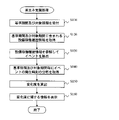
- the equipment operation history information acquisition unit 11 receives the reference period and the target period specified by the user (step 110)
- the equipment operation history information acquisition unit 11 acquires the equipment operation history information included in each of the reference period and the target period from the equipment management device 20 (step 110). Step 120).
- the event occurrence time extraction unit 12 extracts the occurrence time of a predetermined event in each of the reference period and the target period with reference to the acquired equipment operation history information (step 130).
- the predetermined event can be specified from the data type and data value included in the equipment operation history information.
- the predetermined event is, for example, turning on or off the power of the equipment. Specifically, it is a change in the state in which the power supply is switched from off to on and vice versa.
- the equipment is an air-conditioning equipment
- it is an event in which the setting of the air-conditioning equipment is changed so as to meet a predetermined generation condition.
- the predetermined generation condition referred to here is, for example, when the set temperature of the air conditioning equipment is raised or lowered, or when the set temperature is higher than the predetermined temperature, for example, when the temperature is raised or lowered by 2 degrees or more.
- the set temperature of the air conditioning equipment is set to 25 degrees.
- the air volume of the air conditioner is also set to be higher, lower, or stronger than a predetermined threshold value.
- the occurrence of the predetermined event exemplified above can be detected by analyzing the equipment operation history information.
- the predetermined event does not have to be only one, and may be composed of a plurality of events. However, the events to be extracted are the same for the reference period and the target period for comparison.
- the predetermined event may be set in advance.
- the user may be made to specify it together with the reference period and the target period.
- equipment for confirming the occurrence of a predetermined event may be specified.
- the equipment to be processed is set by being incorporated in a predetermined event (for example, "equipment A is set to be on” as a predetermined event), or is specified by a user. It will be described as being limited to the device.
- the change degree calculation unit 13 obtains the distribution of the time of occurrence of the extracted event for each reference period and the target period (step 140).
- FIG. 4 is a diagram showing the number of occurrences of events in each period of the reference period and the target period as a probability density distribution.
- the horizontal axis is time and the vertical axis is the probability density distribution.
- the change degree calculation unit 13 can obtain an operation pattern (broken line shown in FIG. 4) in the equipment to be processed from the distribution of the occurrence time of a predetermined event in the reference period. Similarly, the change degree calculation unit 13 can obtain an operation pattern (solid line shown in FIG. 4) in the equipment to be processed from the distribution of the occurrence time of a predetermined event in the target period.
- the change degree calculation unit 13 calculates the change degree of the operation pattern corresponding to the target period with respect to the operation pattern corresponding to the reference period by comparing the operation patterns of each period (step 150).
- the KL (Kullback-Leibler) divergence of the distribution is calculated as the degree of change.
- the change degree calculation unit 13 may calculate the JS (Jensen-Shannon) divergence of the distribution as the change degree.
- q)) is JS (p
- q) (KL (p
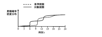
- the change degree calculation unit 13 may calculate the KS (Kolmogorov-Smirnov) test statistic of the cumulative distribution as the change degree.
- FIG. 5 is a diagram showing the number of occurrences of events in each period of the reference period and the target period as a cumulative probability distribution. In FIG. 5, the horizontal axis is time and the vertical axis is the cumulative probability distribution.
- the change degree calculation unit 13 can obtain an operation pattern (broken line shown in FIG. 5) in the equipment to be processed from the cumulative distribution of the occurrence time of a predetermined event in the reference period. Similarly, the change degree calculation unit 13 can obtain an operation pattern (solid line shown in FIG. 5) in the equipment to be processed from the cumulative distribution of the occurrence times of predetermined events in the target period.
- the Anderson-Darling test statistic may be calculated as the degree of change.
- a plurality of events can be set as predetermined events.
- the change degree calculation unit 13 calculates the change degree for each event. Then, a single degree of change is calculated for the equipment by calculating the average value, the median value, the maximum value, the minimum value, and the like of the calculated degree of change of each event.
- weighting may be performed according to the event. For example, the on / off event of the power supply of the equipment has a relatively large influence on the power consumption, so the weighting is relatively large. Further, since the event of raising the temperature setting of the air conditioning equipment once has a relatively small effect on the power consumption, the weighting is relatively small.
- the fact that the degree of change shows a relatively large value means that the operation pattern in the target period has changed relatively significantly with respect to the operation pattern of the equipment in the reference period. Changes in the operation pattern can occur due to changes in the time and number of events that occur. If only the change in the event occurrence time does not change the number of occurrences, the power consumption of the equipment may not change significantly. However, changes in the number of occurrences of events bring about changes in the power consumption of the equipment. For example, when the equipment is an air-conditioning equipment, if the number of events for lowering the set temperature increases in the summer, it is considered that the power consumption increases. On the contrary, if the number of events to lower the set temperature increases in winter, it is considered that the power consumption decreases. In such a case, the power consumption changes relatively significantly.
- the display control unit 14 determines that the power consumption has changed significantly and notifies the user. As a result, the user can start to consider whether or not the energy saving control plan needs to be reviewed.
- the display control unit 14 is made to display information on the degree of change on the display (step 160). ..
- the information output destination does not have to be limited to the display.
- the information may be stored in a file and stored by outputting it to a storage means such as HDD 4.
- the information may be transmitted to another device via the network.
- the display control unit 14 since the information is displayed on the display, the display control unit 14 is provided, but an output control means according to the output destination of the information may be provided.
- FIGS. 6 to 8 are diagrams showing a display example of information regarding the degree of change presented to the user (hereinafter, simply "information").
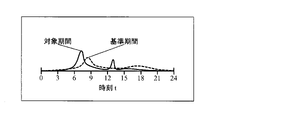
- FIG. 6 shows the probability density distribution of the occurrence time of the power-on event of a certain facility (for example, facility A) in each of the reference period and the target period.
- FIG. 7 shows the probability density distribution of the occurrence time of the power-off event of the equipment A for each of the reference period and the target period.
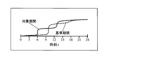
- FIG. 8 shows the cumulative distribution of the occurrence time of the power-on event of the equipment A for each of the reference period and the target period.
- the horizontal axis is time, and as explained with reference to FIG. 4, 24 hours a day is shown.
- the vertical axis of FIGS. 6 and 7 is the probability density distribution
- the vertical axis of FIG. 8 is the cumulative distribution.
- FIG. 6 is a diagram corresponding to FIG. 4 showing a probability distribution when the above-mentioned KL divergence is calculated as a degree of change.
- the user can know the degree of change in power consumption by presenting the numerical value of the degree of change, but specifically, it is not known what kind of change is occurring. Therefore, in the present embodiment, as illustrated in FIGS. 6 to 8, the specific changes in the operation pattern are displayed so as to be visible.
- FIG. 9 is a diagram showing a display example when the degree of change for each equipment is shown in the form of a bar graph.
- the user who referred to the graph shown in FIG. 9 can know that the operation pattern in the equipment B has changed significantly as compared with the previous month.
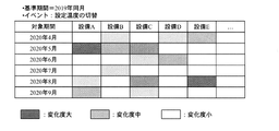
- FIG. 10 is a diagram showing a display example when the degree of change from the previous month for each facility is shown on a heat map.
- the user who referred to the graph shown in FIG. 10 can know the degree of change in the operation pattern with respect to the same month of the previous year in each facility.
- the present embodiment it is possible to present to the user information that can support the formulation of the energy saving control plan.
- the user who refers to the presented display information can take measures such as reviewing the energy saving control plan mainly for the equipment having a large degree of change.
Landscapes
- Engineering & Computer Science (AREA)
- Business, Economics & Management (AREA)
- Physics & Mathematics (AREA)
- General Physics & Mathematics (AREA)
- Health & Medical Sciences (AREA)
- Economics (AREA)
- Power Engineering (AREA)
- Human Resources & Organizations (AREA)
- Water Supply & Treatment (AREA)
- General Health & Medical Sciences (AREA)
- Public Health (AREA)
- Marketing (AREA)
- Primary Health Care (AREA)
- Strategic Management (AREA)
- Tourism & Hospitality (AREA)
- General Business, Economics & Management (AREA)
- Theoretical Computer Science (AREA)
- Management, Administration, Business Operations System, And Electronic Commerce (AREA)
- Supply And Distribution Of Alternating Current (AREA)
- Remote Monitoring And Control Of Power-Distribution Networks (AREA)
Abstract
Description
KL(p||q)=Σtp(t)log(p(t)/q(t))
という計算式にて算出できる。
JS(p||q)=(KL(p||q)+KL(q||p))/2
という計算式にて算出できる。
KS(P,Q)=supt|P(t)-Q(t)|
という計算式にて算出できる。
Claims (7)
- 設備稼働履歴情報を参照することにより、設備の消費電力を解析するための基準となる基準期間及び解析の対象となる対象期間それぞれにおいて、所定のイベントの発生時刻を抽出する発生時刻抽出手段と、
前記基準期間における前記所定のイベントの発生時刻の分布から得られる前記設備の稼働パターンに対する、前記対象期間における前記所定のイベントの発生時刻の分布から得られる設備の稼働パターンの変化度を算出する変化度算出手段と、
前記変化度算出手段により算出された変化度を出力する出力制御手段と、
を有することを特徴とする消費電力監視装置。 - 前記所定のイベントは、前記設備の電源がオン又はオフされた場合であることを特徴とする請求項1に記載の消費電力監視装置。
- 前記所定のイベントは、前記設備が空調設備の場合、前記空調設備の設定が所定の発生条件に合致するよう変更された場合であることを特徴とする請求項1に記載の消費電力監視装置。
- 前記変化度算出手段は、KLダイバージェンス又はJSダイバージェンスを変化度として算出することを特徴とする請求項1に記載の消費電力監視装置。
- 前記変化度算出手段は、KS検定統計量又はアンダーソン・ダーリング検定統計量を変化度として算出することを特徴とする請求項1に記載の消費電力監視装置。
- 前記変化度算出手段は、前記所定のイベントとして複数のイベントが設定されている場合、イベント毎に変化度を算出し、算出した各イベントの変化度に重み付けをして、単一の変化度を算出することを特徴とする請求項1に記載の消費電力監視装置。
- コンピュータを、
設備稼働履歴情報を参照することにより、設備の消費電力を解析するための基準となる基準期間及び解析の対象となる対象期間それぞれにおいて、所定のイベントの発生時刻を抽出する発生時刻抽出手段、
前記基準期間における前記所定のイベントの発生時刻の分布から得られる前記設備の稼働パターンに対する、前記対象期間における前記所定のイベントの発生時刻の分布から得られる設備の稼働パターンの変化度を算出する変化度算出手段、
前記変化度算出手段により算出された変化度を出力する出力制御手段、
として機能させるためのプログラム。
Priority Applications (4)
| Application Number | Priority Date | Filing Date | Title |
|---|---|---|---|
| JP2022564880A JP7442678B2 (ja) | 2020-11-25 | 2020-11-25 | 消費電力監視装置及びプログラム |
| CN202080107386.XA CN116724475B (zh) | 2020-11-25 | 2020-11-25 | 消耗电力监视装置 |
| PCT/JP2020/043804 WO2022113201A1 (ja) | 2020-11-25 | 2020-11-25 | 消費電力監視装置及びプログラム |
| US18/200,106 US20230305043A1 (en) | 2020-11-25 | 2023-05-22 | Power consumption monitoring apparatus |
Applications Claiming Priority (1)
| Application Number | Priority Date | Filing Date | Title |
|---|---|---|---|
| PCT/JP2020/043804 WO2022113201A1 (ja) | 2020-11-25 | 2020-11-25 | 消費電力監視装置及びプログラム |
Related Child Applications (1)
| Application Number | Title | Priority Date | Filing Date |
|---|---|---|---|
| US18/200,106 Continuation US20230305043A1 (en) | 2020-11-25 | 2023-05-22 | Power consumption monitoring apparatus |
Publications (1)
| Publication Number | Publication Date |
|---|---|
| WO2022113201A1 true WO2022113201A1 (ja) | 2022-06-02 |
Family
ID=81755381
Family Applications (1)
| Application Number | Title | Priority Date | Filing Date |
|---|---|---|---|
| PCT/JP2020/043804 Ceased WO2022113201A1 (ja) | 2020-11-25 | 2020-11-25 | 消費電力監視装置及びプログラム |
Country Status (4)
| Country | Link |
|---|---|
| US (1) | US20230305043A1 (ja) |
| JP (1) | JP7442678B2 (ja) |
| CN (1) | CN116724475B (ja) |
| WO (1) | WO2022113201A1 (ja) |
Citations (8)
| Publication number | Priority date | Publication date | Assignee | Title |
|---|---|---|---|---|
| JPH04372046A (ja) * | 1991-06-20 | 1992-12-25 | Hitachi Ltd | 需要量予測方法及び装置 |
| JPH099502A (ja) * | 1995-06-23 | 1997-01-10 | Mitsubishi Electric Corp | デマンド制御装置 |
| WO2011024366A1 (ja) * | 2009-08-28 | 2011-03-03 | パナソニック株式会社 | 利用時間変更支援装置およびその方法 |
| JP2013009500A (ja) * | 2011-06-24 | 2013-01-10 | Fujitsu Ltd | 電力管理装置 |
| WO2015151558A1 (ja) * | 2014-03-31 | 2015-10-08 | 日本電気株式会社 | 監視装置、監視システム、監視方法及びプログラム |
| JP2016165209A (ja) * | 2014-07-11 | 2016-09-08 | エンコアード テクノロジーズ インク | 電力需要の管理機能を有するサーバ、通信機器、システムおよび電力使用管理方法 |
| WO2017090172A1 (ja) * | 2015-11-27 | 2017-06-01 | 三菱電機株式会社 | 情報収集ユニット、情報処理方法およびプログラム |
| JP2018124727A (ja) * | 2017-01-31 | 2018-08-09 | 株式会社東芝 | 電力需要予測装置 |
Family Cites Families (10)
| Publication number | Priority date | Publication date | Assignee | Title |
|---|---|---|---|---|
| WO2009125627A1 (ja) * | 2008-04-11 | 2009-10-15 | 三菱電機株式会社 | 機器状態検出装置及び機器状態検出方法並びに生活者異常検知装置、生活者異常検知システム及び生活者異常検知方法 |
| JP5475546B2 (ja) * | 2010-05-25 | 2014-04-16 | パナソニック株式会社 | 省エネ診断システム |
| KR101828461B1 (ko) * | 2011-02-01 | 2018-03-29 | 삼성전자주식회사 | 전기기기, 전력 관리기 및 그 제어 방법 |
| WO2014126131A1 (ja) * | 2013-02-13 | 2014-08-21 | 株式会社構造計画研究所 | 生活行動推定システム、生活行動推定装置、生活行動推定プログラム、及び記録媒体 |
| GB2535713A (en) * | 2015-02-24 | 2016-08-31 | Energy Tech Inst Llp | Method and apparatus for controlling an environment management system within a building |
| CN107134851A (zh) * | 2017-05-03 | 2017-09-05 | 成都富驰达科技有限公司 | 一种基于建筑信息模型的光伏电站智能运维方法和系统 |
| CN109739720B (zh) * | 2018-12-04 | 2022-08-02 | 东软集团股份有限公司 | 异常检测方法、装置、存储介质和电子设备 |
| CN111751814A (zh) * | 2019-03-29 | 2020-10-09 | 富士通株式会社 | 基于无线信号的运动状态检测装置、方法及系统 |
| US11544634B2 (en) * | 2019-06-27 | 2023-01-03 | Royal Bank Of Canada | System and method for detecting data drift |
| CN111551773A (zh) * | 2020-05-14 | 2020-08-18 | 资明 | 一种智能电力管理系统 |
-
2020
- 2020-11-25 CN CN202080107386.XA patent/CN116724475B/zh active Active
- 2020-11-25 JP JP2022564880A patent/JP7442678B2/ja active Active
- 2020-11-25 WO PCT/JP2020/043804 patent/WO2022113201A1/ja not_active Ceased
-
2023
- 2023-05-22 US US18/200,106 patent/US20230305043A1/en active Pending
Patent Citations (8)
| Publication number | Priority date | Publication date | Assignee | Title |
|---|---|---|---|---|
| JPH04372046A (ja) * | 1991-06-20 | 1992-12-25 | Hitachi Ltd | 需要量予測方法及び装置 |
| JPH099502A (ja) * | 1995-06-23 | 1997-01-10 | Mitsubishi Electric Corp | デマンド制御装置 |
| WO2011024366A1 (ja) * | 2009-08-28 | 2011-03-03 | パナソニック株式会社 | 利用時間変更支援装置およびその方法 |
| JP2013009500A (ja) * | 2011-06-24 | 2013-01-10 | Fujitsu Ltd | 電力管理装置 |
| WO2015151558A1 (ja) * | 2014-03-31 | 2015-10-08 | 日本電気株式会社 | 監視装置、監視システム、監視方法及びプログラム |
| JP2016165209A (ja) * | 2014-07-11 | 2016-09-08 | エンコアード テクノロジーズ インク | 電力需要の管理機能を有するサーバ、通信機器、システムおよび電力使用管理方法 |
| WO2017090172A1 (ja) * | 2015-11-27 | 2017-06-01 | 三菱電機株式会社 | 情報収集ユニット、情報処理方法およびプログラム |
| JP2018124727A (ja) * | 2017-01-31 | 2018-08-09 | 株式会社東芝 | 電力需要予測装置 |
Also Published As
| Publication number | Publication date |
|---|---|
| US20230305043A1 (en) | 2023-09-28 |
| CN116724475B (zh) | 2025-11-18 |
| JPWO2022113201A1 (ja) | 2022-06-02 |
| CN116724475A (zh) | 2023-09-08 |
| JP7442678B2 (ja) | 2024-03-04 |
Similar Documents
| Publication | Publication Date | Title |
|---|---|---|
| CN111459700A (zh) | 设备故障的诊断方法、诊断装置、诊断设备及存储介质 | |
| Harmer et al. | Using calibrated energy models for building commissioning and load prediction | |
| CN116796043A (zh) | 一种智能园区数据可视化方法及系统 | |
| JP2015011027A (ja) | 時系列データにおける異常を検出する方法 | |
| Salimi et al. | Sensitivity analysis of probabilistic occupancy prediction model using big data | |
| KR20220104460A (ko) | 병원 에너지 관리 시스템 및 그 관리 방법 | |
| JP5933386B2 (ja) | データ管理装置及びプログラム | |
| CN116739619B (zh) | 一种能源电力碳排放监测分析建模方法及装置 | |
| JP2022050354A (ja) | 特徴量選別方法及び健康状態評価方法 | |
| CN119939700A (zh) | 一种基于bim的绿色建筑信息集成管理方法及系统 | |
| US12228295B2 (en) | Area-specific environment management system for providing environment in which arousal level is adjusted, method, and recording medium therefor | |
| CN115032270B (zh) | 基于机器学习算法建筑幕墙损伤状态定量识别方法及装置 | |
| Shen et al. | Using PeopleHour for occupant-centric office building performance assessment | |
| CN113465734B (zh) | 一种结构振动的实时估计方法 | |
| WO2022113201A1 (ja) | 消費電力監視装置及びプログラム | |
| Dabirian et al. | Gaussian-based plug load profile prediction in non-residential buildings archetype | |
| CN119006244B (zh) | 基于虚拟仿真的实训教学管理方法 | |
| US11372399B2 (en) | System section data management device and method thereof | |
| CN115345190A (zh) | 信号异常的检测方法、装置及服务器 | |
| JP2013156941A (ja) | 在宅管理装置、在宅管理方法および在宅管理プログラム | |
| JP6024510B2 (ja) | 消費エネルギー分析装置、消費エネルギー分析方法及びコンピュータプログラム | |
| CN118644030A (zh) | 一种工程造价进度的实时动态跟踪方法及装置 | |
| JP6880864B2 (ja) | エネルギー管理システムおよびエネルギー管理方法 | |
| JP2024162111A (ja) | 異常検知システム | |
| Li et al. | Evidence-based strategies for optimizing long-term temperature monitoring in offices |
Legal Events
| Date | Code | Title | Description |
|---|---|---|---|
| 121 | Ep: the epo has been informed by wipo that ep was designated in this application |
Ref document number: 20963466 Country of ref document: EP Kind code of ref document: A1 |
|
| ENP | Entry into the national phase |
Ref document number: 2022564880 Country of ref document: JP Kind code of ref document: A |
|
| WWE | Wipo information: entry into national phase |
Ref document number: 202080107386.X Country of ref document: CN |
|
| NENP | Non-entry into the national phase |
Ref country code: DE |
|
| 122 | Ep: pct application non-entry in european phase |
Ref document number: 20963466 Country of ref document: EP Kind code of ref document: A1 |