WO2022107427A1 - ルーフ駆動装置 - Google Patents
ルーフ駆動装置 Download PDFInfo
- Publication number
- WO2022107427A1 WO2022107427A1 PCT/JP2021/033121 JP2021033121W WO2022107427A1 WO 2022107427 A1 WO2022107427 A1 WO 2022107427A1 JP 2021033121 W JP2021033121 W JP 2021033121W WO 2022107427 A1 WO2022107427 A1 WO 2022107427A1
- Authority
- WO
- WIPO (PCT)
- Prior art keywords
- guide
- roof
- guide body
- frame
- pair
- Prior art date
- Legal status (The legal status is an assumption and is not a legal conclusion. Google has not performed a legal analysis and makes no representation as to the accuracy of the status listed.)
- Ceased
Links
Images


Classifications
-
- B—PERFORMING OPERATIONS; TRANSPORTING
- B60—VEHICLES IN GENERAL
- B60J—WINDOWS, WINDSCREENS, NON-FIXED ROOFS, DOORS, OR SIMILAR DEVICES FOR VEHICLES; REMOVABLE EXTERNAL PROTECTIVE COVERINGS SPECIALLY ADAPTED FOR VEHICLES
- B60J7/00—Non-fixed roofs; Roofs with movable panels, e.g. rotary sunroofs
- B60J7/02—Non-fixed roofs; Roofs with movable panels, e.g. rotary sunroofs of sliding type, e.g. comprising guide shoes
- B60J7/04—Non-fixed roofs; Roofs with movable panels, e.g. rotary sunroofs of sliding type, e.g. comprising guide shoes with rigid plate-like element or elements, e.g. open roofs with harmonica-type folding rigid panels
- B60J7/057—Driving or actuating arrangements e.g. manually operated levers or knobs
-
- E—FIXED CONSTRUCTIONS
- E05—LOCKS; KEYS; WINDOW OR DOOR FITTINGS; SAFES
- E05F—DEVICES FOR MOVING WINGS INTO OPEN OR CLOSED POSITION; CHECKS FOR WINGS; WING FITTINGS NOT OTHERWISE PROVIDED FOR, CONCERNED WITH THE FUNCTIONING OF THE WING
- E05F11/00—Man-operated mechanisms for operating wings, including those which also operate the fastening
- E05F11/53—Man-operated mechanisms for operating wings, including those which also operate the fastening for sliding windows, e.g. vehicle windows, to be opened or closed by horizontal movement
-
- E—FIXED CONSTRUCTIONS
- E05—LOCKS; KEYS; WINDOW OR DOOR FITTINGS; SAFES
- E05F—DEVICES FOR MOVING WINGS INTO OPEN OR CLOSED POSITION; CHECKS FOR WINGS; WING FITTINGS NOT OTHERWISE PROVIDED FOR, CONCERNED WITH THE FUNCTIONING OF THE WING
- E05F15/00—Power-operated mechanisms for wings
- E05F15/60—Power-operated mechanisms for wings using electrical actuators
- E05F15/603—Power-operated mechanisms for wings using electrical actuators using rotary electromotors
- E05F15/632—Power-operated mechanisms for wings using electrical actuators using rotary electromotors for horizontally-sliding wings
- E05F15/655—Power-operated mechanisms for wings using electrical actuators using rotary electromotors for horizontally-sliding wings specially adapted for vehicle wings
Definitions
- the present disclosure relates to a roof drive device that drives a vehicle roof member.
- a drive device for an automobile roof is known to include a guide rail provided with a cable channel and a drive cable displaced by a pinion in order to transmit a driving force to a displaceable roof member (Patent Document). 1).
- the drive cable is guided by a cable channel and, near the pinion of the guide rail, by a wear-resistant cable guide fitted into an opening formed in the guide rail.
- the cable guide is made of spring steel and has two guide legs extending along the drive cable and two claws located between the drive cables facing each other and extending at right angles to the guide legs.
- Each claw has an inner leg and an outer leg, and is configured in a V-shape or an inverted V-shape when viewed in cross section, and the free end of the outer leg supports the inner surface (the surface defining the cable channel) of the guide rail. Will be done.
- a transmission gear mechanism of a drive motor provided with a shaft for driving a drive pinion is attached to the lower surface of the guide rail, and a transmission gear mechanism of a drive motor is attached to an opening formed on the upper surface of the guide rail from above.
- the cable guide is fitted. Therefore, the cable guide may come off. Further, the cable guide is formed in a size that can be fitted into the opening so that the free end of the outer leg is supported by the inner surface of the guide rail. That is, the cable guide causes rattling even when it is fitted in the opening of the guide rail. Therefore, an abnormal noise is generated when the drive cable is driven.
- an embodiment of the present invention is a roof drive device (20) that drives the roof members (18, 21) of a vehicle, and a frame that supports the roof members in a displaceable manner.
- a drive source (24) having an output shaft (32) provided with a drive gear (34) and attached to the frame with the output shaft facing in the vertical direction, and a roof member at one end thereof.
- a pair of power transmission members (25) having a driven gear (35) arranged at a position sandwiching the drive gear in the vicinity of the drive source so as to be connected and meshed with the drive gear, and in the vicinity of the drive gear.
- a pair of holding portions (52) extending from both ends in the extending direction of the main body toward the drive source side and holding the power transmission member, and both ends in the width direction orthogonal to the extending direction of the guide main body. It has a pair of engaging claws (54, 64) that engage the frame in order to restrict the movement of the guide body in the width direction, and the frame is provided in the vertical direction of the guide member.
- first contact wall (57) that abuts on the guide body from the side opposite to the drive source in order to regulate the movement, and on the outer surface of the holding portion in order to regulate the elongation deformation of the guide member in the extending direction. It has a pair of second contact walls (58) that come into contact with each other, and the engaging claw has a locking surface on the side opposite to the drive source of the frame in order to restrict the vertical movement of the guide body. Reflexively engages (56, 66).
- the first contact wall of the frame that restricts the vertical movement of the guide member abuts on the guide body from the side opposite to the drive source, so that the guide member comes into contact with the drive source and the first contact wall. It is sandwiched by. Therefore, even if the engaging claw is disengaged, there is no possibility that the guide member will be disengaged. Further, the engaging claw of the guide member not only regulates the movement of the guide body in the width direction, but also repels the locking surface on the side opposite to the drive source of the frame in order to regulate the movement of the guide body in the vertical direction. Engage. As a result, the guide main body is pressed against the first contact wall by the elastic force of the engaging claw, so that the rattling of the guide member is suppressed.
- the roof drive device further comprises at least a pair of guide pipes (26) inserted into the frame to guide the power transmission member, with the first contact wall at least at the end of the guide pipe.
- the bridge-shaped portion (42) is hung over an opening (41) formed through the frame so that the portion is exposed, and is arranged on the side opposite to the drive source with respect to the guide main body.
- the guide member (50) extends substantially perpendicular to the guide body from both ends of the guide body in the width direction and supports the corresponding engaging claws (55). ), And the locking surfaces (56) are formed on both sides of the bridge-shaped portion, and the free end edges of the engaging claws (54) are inclined in the vertical direction with respect to the locking surface.
- the locking surface (56) is inclined with respect to the width direction of the guide body.
- the guide member (60) further comprises a pair of claw support pieces (65) that extend in the width direction from both ends of the guide body in the width direction and support the corresponding engaging claws.
- the locking surface (66) is formed on both sides of the opening, and the free end edge of the engaging claw (64) is inclined in the vertical direction with respect to the locking surface (66). Contact.
- the guide member since the engaging claw abuts on the locking surfaces formed on both sides of the opening from the direction in which the engaging claw is inclined with respect to the vertical direction, the guide member rattles in the vertical direction and the width direction of the guide body. Sticking is suppressed.
- the second contact wall is a ridge (58) protruding from the surface (lower surface) of the bridge-shaped portion on the side that abuts on the guide main body, and is formed on the guide main body of the bridge-shaped portion.
- a plurality of ribs (59) extending from the ridge to the end of the bridge-shaped portion are formed on the surface on the abutting side.
- the holding portion that receives a large load when the roof member is driven or when the vehicle collides is supported by the ridges imparted with high rigidity by a plurality of ribs, so that the guide member is stretched and deformed. Both suppression and weight reduction of the frame are achieved.
- the free end of the sandwiching portion (52) is curved inward.
- the power transmission member since the power transmission member is sandwiched from above and below by the guide body of the guide member and the free end of the holding portion, the power transmission member is not only displaced in the direction away from the drive source but also in the direction toward the drive source. Displacement is also suppressed.
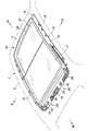
- FIG. 1 A perspective view of the sunroof device according to the first embodiment as viewed from the rear.
- Top view of the rear of the sunroof device shown in FIG. Bottom view of part III in FIG. IV-IV cross-sectional view in FIG.
- Enlarged perspective view of the main part of the frame shown in FIG. Bottom view showing an enlarged view of the main part of the frame shown in FIG.
- the front-back and left-right directions are used with reference to the traveling direction of the automobile 1 provided with the sunroof device 10. Further, it is referred to as the inside and the outside of the sunroof device 10 with reference to the left-right direction (vehicle width direction) and the up-down direction of the automobile 1.
- FIG. 1 is a perspective view of the sunroof device 10 according to the first embodiment as viewed from the rear.
- a sunroof device 10 is attached to the roof 2 of the automobile 1.
- the sunroof device 10 is mounted on the roof 2 so as to close the opening formed in the roof 2.
- the sunroof device 10 has an outer panel 11 arranged on the outer side (upper side), an inner shade 12 arranged on the inner side (lower side), and a frame 13 for supporting the outer panel 11 and the inner shade 12.
- the frame 13 has left and right side members 14 extending in the front-rear direction, a resin rear cross member 15 connecting the rear ends of the side members 14, and a resin front cross member 16 connecting the front ends of the side members 14. And have.
- the frame 13 has a rectangular shape formed by these members, and is fixed to the roof 2 by an appropriate means.
- the side member 14 includes a metal roof guide rail and a shade guide rail extending in the front-rear direction.
- the outer panel 11 is divided into two in the front-rear direction, and has a rear fixed panel 17 fixed to the roof 2 and a front movable panel 18 displaceable with respect to the roof 2.
- the movable panel 18 may be an inner slide type or an outer slide type slide panel that can be displaced in the front-rear direction, or may be a tilt panel that only performs a tilt operation.
- the movable panel 18 is driven by the first roof drive device 20 (roof panel drive device) provided in the sunroof device 10.
- the movable panel 18 may be provided behind the outer panel 11, or the outer panel 11 may be composed of only the movable panel 18.
- the inner shade 12 includes a take-up shaft provided at the rear end of the frame 13, a shade sheet 21 wound around the take-up shaft so that it can be taken up and pulled out, and a crossbar 22 attached to the front end of the shade sheet 21. It is equipped with.
- the inner shade 12 is unfolded and wound driven by sliding the crossbar 22 back and forth by a second roof drive device 20 (roof shade drive device) provided in the sunroof device 10.
- the inner shade 12 may be provided with a shade panel instead of the shade sheet 21.
- the shade panel is divided into a plurality of shade panels in the front-rear direction, and the shade panel members are connected to each other so as to be in a stored state in which the shade panel members overlap each other and an extended unfolded state.
- the shade panel is driven to the expanded state or the retracted state by sliding the inner panel member arranged at the front end back and forth by the second roof driving device 20 provided in the sunroof device 10.
- the movable panel 18, the shade sheet 21, and the shade panel member are displaceably provided roof members on the roof 2, and are displaceably supported by the frame 13.
- FIG. 2 is a plan view of the rear part of the sunroof device 10 shown in FIG.
- two mounting portions 23 for mounting the drive source 24 of the roof drive device 20 are provided on the rear cross member 15 at different positions in the left-right direction.
- the drive source 24 of the roof drive device 20 that drives the movable panel 18 is attached to one of the attachment portions 23, and the drive source 24 of the roof drive device 20 that drives the shade sheet 21 is attached to the other.
- These drive sources 24 transmit power via a pair of power transmission members 25 (see FIG. 4) connected to a movable panel 18 which is a roof member and a shade sheet 21 at one end, and the corresponding movable panels 18 Drives the shade sheet 21 or the shade panel member.
- the power transmission member 25 extends in the left-right direction at the mounting portion 23.
- the power transmission member 25 is a push-pull cable in which a wire is spirally wound around the outer peripheral surface of a flexible steel body.
- the power transmission member 25 may be configured by a flexible rack belt with gears formed on one side.
- the power transmission member 25 is guided by a steel guide pipe 26 attached to the frame 13, extends forward through a guide groove formed in the side member 14, and has a roof at one end via a slider, a stay, a crossbar 22, and the like. It is connected to the left and right sides of the member.
- the configurations of the roof drive device 20 for driving the movable panel 18 and the roof drive device 20 for driving the shade sheet 21 are substantially the same. Hereinafter, the configuration of the roof drive device 20 for driving the movable panel 18 will be described on behalf of these.
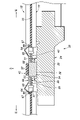
- FIG. 3 is a bottom view of part III in FIG. 2, and FIG. 4 is a sectional view taken along line IV-IV in FIG.
- the drive source 24 of the roof drive device 20 includes an electric motor 31 and a speed reducer 33 having an output shaft 32 extending in a direction orthogonal to the rotation axis 31A of the electric motor 31.
- the drive source 24 is attached to the mounting portion 23 of the rear cross member 15 from below with the rotation axis 31A of the electric motor 31 oriented in the left-right direction and the output shaft 32 oriented in the vertical direction.
- the output shaft 32 of the drive source 24 is provided with a drive gear 34 for driving the power transmission member 25.
- the drive gear 34 is a pinion made of helical gears, and the power transmission member 25 can be driven in the extending direction by engaging with the driven gear 35 provided in the power transmission member 25.
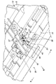
- FIG. 5 is an enlarged perspective view showing a main part of the frame 13 shown in FIG. 1
- FIG. 6 is a bottom view showing an enlarged main part of the frame 13 shown in FIG.
- the pair of power transmission members 25 are arranged at intervals in the front-rear direction so as to sandwich the drive gear 34 in the vicinity of the drive source 24. That is, the driven gear 35 (FIG. 4) of the pair of power transmission members 25 is arranged at a position sandwiching the drive gear 34 so as to mesh with the drive gear 34.
- the rear cross member 15 is injection-molded by inserting a steel guide pipe 26 that guides the drive portion (power transmission portion) from the meshing portion of the power transmission member 25 with the drive gear 34 to the movable panel 18.
- a large driving force is not transmitted to the idle portion on the free end side opposite to the drive portion with respect to the meshing portion of the power transmission member 25. Therefore, the guide pipe 26 that guides the idle portion of the power transmission member 25 is fitted from below into the groove formed on the lower surface of the rear cross member 15 after the rear cross member 15 is formed.
- an opening 41 penetrating in the vertical direction is formed in order to hold the guide pipe 26 inserted at the time of molding in the mold of the rear cross member 15.
- a bridge-shaped portion 42 extending in the front-rear direction is bridged over the opening 41.
- the bridge-shaped portion 42 extends in the front-rear direction at a position offset upward from the mounting portion 23 of the rear cross member 15.
- a recess 43 (FIG. 4) is formed in which the left and right portions of the bridge-shaped portion 42 penetrate vertically and are opened downward. ..
- the end portion of the guide pipe 26 on the drive gear 34 side is located at the penetrating portion of the opening 41 formed on the left and right of the bridge-shaped portion 42.
- a large load is transmitted to the pair of power transmission members 25 when the movable panel 18 is driven or when a vehicle collides.
- the driven gear 35 becomes loosely meshed with the drive gear 34. Therefore, in the vicinity of the drive gear 34, that is, in the recess 43 of the mounting portion 23 in which the drive gear 34 is arranged, a guide member 50 that guides the pair of power transmission members 25 so as not to separate from each other is provided.
- the guide member 50 is made of a spring steel plate.
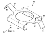
- FIG. 7 is a perspective view of the guide member 50 shown in FIG.
- the guide member 50 includes a guide body 51 extending in the front-rear direction so as to cross the power transmission member 25.
- a pair of holding portions 52 extending downward toward the drive source 24 side and holding a pair of front-rear power transmission members 25 are integrally provided.
- the guide body 51 is formed with a through hole 53 having a size capable of receiving the drive gear 34.
- the free ends of the pair of holding portions 52 are curved inward, and the holding portions 52 form a U-shape in cooperation with the guide main body 51 so that the corresponding power transmission member 25 can be formed from above and below. I'm sandwiching it.
- the U-shaped portion of the guide member 50 has a tapered shape that expands in diameter toward both ends in the left-right direction.
- the guide member 50 has a pair of engaging claws 54 provided at both ends of the guide main body 51 in the left-right direction (that is, the width direction orthogonal to the extending direction).
- the engaging claw 54 is supported by a pair of claw support pieces 55 extending upward substantially perpendicular to the guide main body 51 from the left and right ends of the guide main body 51, and by engaging with the frame 13, the guide main body 51 Regulate the movement of the left and right direction.
- a pair of engaging claws 54 are formed before and after each claw support piece 55.
- a pair of locking surfaces 56 inclined with respect to the left-right direction and the up-down direction are formed on both side portions of the bridge-shaped portion 42.
- the locking surface 56 is symmetrical in cross section.
- the engaging claw 54 extends inward and downward in the left-right direction of the guide main body 51 from the claw support piece 55, and the free end of the engaging claw 54 extends in the vertical direction with respect to the locking surface 56 of the bridge-shaped portion 42. On the other hand, they are in contact with each other at a right angle from the direction of inclination.
- the guide member 50 is inserted into the recess 43 of the mounting portion 23 of the rear cross member 15 from below, and after elastically deforming the pair of engaging claws 54, the free ends of the pair of engaging claws 54 are bridge-shaped portions 42. Is attached to the bridge-shaped portion 42 by elastically engaging with the locking surface 56 of the above. In this mounted state, the guide member 50 brings the guide main body 51 into contact with the lower surface of the bridge-shaped portion 42 with an urging force due to the elastic force of the engaging claw 54. That is, the engaging claw 54 elastically engages with the locking surface 56 on the side opposite to the drive source 24 of the frame 13, thereby restricting the vertical movement of the guide main body 51.
- the bridge-shaped portion 42 forms a first contact wall 57 that abuts on the guide main body 51 from above, and restricts the vertical movement of the guide member 50.
- a pair of ridges 58 extending to the left and right are formed so as to protrude in the front-rear direction on the lower surface of the bridge-shaped portion 42.
- the pair of ridges 58 form a second contact wall that abuts on the outer surface of the holding portion 52 of the guide member 50, and regulates the elongation deformation of the guide member 50 in the front-rear direction.
- a plurality of ribs 59 extending from each ridge 58 to the end of the bridge-shaped portion 42 are formed.
- the roof drive device 20 is configured as described above. Next, the operation and effect of the roof drive device 20 configured in this way will be described.
- the first contact wall 57 of the frame 13 that restricts the vertical movement of the guide member 50 is in contact with the guide body 51 from the side opposite to the drive source 24, and is a guide.
- the member 50 is sandwiched between the first contact wall 57 and the drive source 24. Therefore, even if the engaging claw 54 is disengaged, there is no possibility that the guide member 50 will be disengaged.
- the engaging claw 54 of the guide member 50 not only regulates the movement of the guide body 51 in the left-right direction, but also regulates the movement of the guide body 51 in the vertical direction on the side opposite to the drive source 24 of the frame 13. It elastically engages with the locking surface 56. As a result, the guide main body 51 is pressed against the first contact wall 57 by the elastic force of the engaging claw 54, so that the rattling of the guide member 50 is suppressed.
- a guide pipe 26 is provided in the vicinity of the guide member 50, and the guide pipe 26 is inserted into the frame 13. Therefore, it is possible to prevent the power transmission member 25 from being largely displaced inside the guide member 50. As a result, the rattling of the guide member 50 is suppressed.
- the free end edge of the engaging claw 54 abuts on the locking surface 56 of the bridge-shaped portion 42 from a direction inclined with respect to the vertical direction. Therefore, rattling of the guide member 50 is suppressed in the vertical direction and the horizontal direction.
- the locking surface 56 is inclined in the left-right direction, that is, in the width direction of the guide main body 51. Therefore, the rattling of the guide member 50 is suppressed regardless of the position of the locking surface 56 where the free end edge of the engaging claw 54 is inclined. In other words, even if there is a manufacturing error in the bridge shape portion 42 or the guide member 50, the engaging claw 54 reliably and elastically abuts on the locking surface 56.
- the second contact wall is composed of ridges 58 protruding from the lower surface of the bridge-shaped portion 42, and a plurality of ribs 59 extending from the ridges 58 to the end of the bridge-shaped portion 42 bridge. It is formed on the lower surface of the shape portion 42. Therefore, the holding portion 52, which receives a large load when the movable panel 18 is driven or when the vehicle collides, is supported by the ridges 58 which are provided with high rigidity by the plurality of ribs 59, so that the guide member 50 is supported in the front-rear direction.
- the suppression of the elongation deformation of the frame 13 and the weight reduction of the frame 13 are compatible with each other.
- the free end of the sandwiching portion 52 is curved inward.
- the power transmission member 25 is sandwiched from above and below by the guide main body 51 of the guide member 50 and the free end of the sandwiching portion 52. Therefore, not only the upward displacement of the power transmission member 25 away from the drive source 24 but also the downward displacement approaching the drive source 24 is suppressed.
- FIG. 8 is a cross-sectional view corresponding to FIG. 4 of the sunroof device 10 according to the second embodiment
- FIG. 9 is an enlarged plan view showing a main part of the frame 13 shown in FIG. 8
- FIG. 10 is a view. It is a perspective view of the guide member 60 shown in 8.
- the configuration of the guide member 60 is mainly different from that of the first embodiment.
- the guide member 60 has a pair of engaging claws 64 provided at both ends of the guide main body 51 in the left-right direction (that is, the width direction orthogonal to the extending direction).
- the engaging claw 64 is supported by a pair of claw support pieces 65 extending in the left-right direction from the left and right ends of the guide body 51, and by engaging with the frame 13, the movement of the guide body 51 in the left-right direction is restricted. ..
- the claw support piece 65 extends upward from the guide main body 51 toward the outside in the left-right direction, and the engaging claw 64 extends downward from the extending end of the claw support piece 65 toward the outside in the left-right direction. These have an inverted V-shape with an obtuse angle in cross-sectional view.
- a locking wall 67 extending in the front-rear direction to form a locking surface 66 is formed in the opening 41. It is formed so as to project slightly away from the inner edge.
- the locking surface 66 is composed of an upward surface of the mounting portion 23 and an inward surface of the locking wall 67.
- the free end of the engaging claw 64 abuts on the corner of the locking surface 66 from a direction inclined in the vertical direction with respect to the locking surfaces 66 formed on both sides of the opening 41 in the mounting portion 23.
- the engaging claw 64 abuts on the locking surfaces 66 formed on both sides of the opening 41 from the direction in which the engaging claw 64 is inclined in the vertical direction. Therefore, rattling of the guide member 60 is suppressed in the vertical direction and the horizontal direction.
- the present invention can be widely modified without being limited to the above embodiment.
- the sunroof device 10 has been described as an example for the automobile 1, but the present invention can be widely applied to railway vehicles and the like.
- the drive source 24 is attached to the rear portion of the frame 13, but the drive source 24 may be attached to the front portion or the side portion of the frame 13.
- the movable panel 18 and the shade sheet 21 forming the roof member may be driven in the left-right direction.
- the specific configuration and arrangement of each member and portion, quantity, angle, material, and the like can be appropriately changed as long as they do not deviate from the gist of the present invention.
- not all of the components shown in the above embodiments are indispensable, and they can be appropriately selected.
Landscapes
- Engineering & Computer Science (AREA)
- Mechanical Engineering (AREA)
- Power-Operated Mechanisms For Wings (AREA)
Priority Applications (1)
| Application Number | Priority Date | Filing Date | Title |
|---|---|---|---|
| JP2022563591A JP7343720B2 (ja) | 2020-11-17 | 2021-09-09 | ルーフ駆動装置 |
Applications Claiming Priority (2)
| Application Number | Priority Date | Filing Date | Title |
|---|---|---|---|
| JP2020-190754 | 2020-11-17 | ||
| JP2020190754 | 2020-11-17 |
Publications (1)
| Publication Number | Publication Date |
|---|---|
| WO2022107427A1 true WO2022107427A1 (ja) | 2022-05-27 |
Family
ID=81708750
Family Applications (1)
| Application Number | Title | Priority Date | Filing Date |
|---|---|---|---|
| PCT/JP2021/033121 Ceased WO2022107427A1 (ja) | 2020-11-17 | 2021-09-09 | ルーフ駆動装置 |
Country Status (2)
| Country | Link |
|---|---|
| JP (1) | JP7343720B2 (https=) |
| WO (1) | WO2022107427A1 (https=) |
Citations (3)
| Publication number | Priority date | Publication date | Assignee | Title |
|---|---|---|---|---|
| JPS5043427U (https=) * | 1973-08-22 | 1975-05-01 | ||
| JP2009280122A (ja) * | 2008-05-23 | 2009-12-03 | Yachiyo Industry Co Ltd | サンルーフ装置における駆動用モータのブラケット構造 |
| WO2017102181A1 (de) * | 2015-12-17 | 2017-06-22 | Bos Gmbh & Co. Kg | Dachmodul für ein fahrzeugdach eines personenkraftwagens |
-
2021
- 2021-09-09 WO PCT/JP2021/033121 patent/WO2022107427A1/ja not_active Ceased
- 2021-09-09 JP JP2022563591A patent/JP7343720B2/ja active Active
Patent Citations (3)
| Publication number | Priority date | Publication date | Assignee | Title |
|---|---|---|---|---|
| JPS5043427U (https=) * | 1973-08-22 | 1975-05-01 | ||
| JP2009280122A (ja) * | 2008-05-23 | 2009-12-03 | Yachiyo Industry Co Ltd | サンルーフ装置における駆動用モータのブラケット構造 |
| WO2017102181A1 (de) * | 2015-12-17 | 2017-06-22 | Bos Gmbh & Co. Kg | Dachmodul für ein fahrzeugdach eines personenkraftwagens |
Also Published As
| Publication number | Publication date |
|---|---|
| JP7343720B2 (ja) | 2023-09-12 |
| JPWO2022107427A1 (https=) | 2022-05-27 |
Similar Documents
| Publication | Publication Date | Title |
|---|---|---|
| JP4726975B2 (ja) | サンルーフ装置 | |
| JP4789588B2 (ja) | 車両用スライドドア開閉装置 | |
| JP4486687B2 (ja) | サンルーフ装置 | |
| JP5598263B2 (ja) | 車両用ルーフ装置 | |
| US8240752B2 (en) | Holding structure of guide pipe of sunroof apparatus | |
| JP5108903B2 (ja) | 車両ルーフ構造 | |
| JP2011156938A (ja) | 車両ルーフ構造 | |
| JP2011156937A (ja) | 車両ルーフ構造 | |
| JP3659632B2 (ja) | スライディングルーフ装置 | |
| WO2010110115A1 (ja) | 車両用ルーフ装置 | |
| JP5456439B2 (ja) | サンルーフ装置及び遮蔽体 | |
| WO2022107427A1 (ja) | ルーフ駆動装置 | |
| KR102530211B1 (ko) | 차량용 시트의 슬라이딩 장치 | |
| CN102009582B (zh) | 具有电动拉门的车辆的操作缆线的布缆构造 | |
| JP5076840B2 (ja) | 開閉体駆動用ラックベルト及び該開閉体駆動用ラックベルトを用いた開閉体駆動装置 | |
| JP4504847B2 (ja) | ロールサンシェード装置 | |
| JP5640720B2 (ja) | 車両用サンシェード | |
| JP2018154160A (ja) | 車両用サンルーフ装置 | |
| JP2002154329A (ja) | スライディングルーフ装置 | |
| CN205632064U (zh) | 天窗装置 | |
| US12502939B2 (en) | Roof module for vehicle | |
| JP5541441B2 (ja) | 自動車用サンバイザー | |
| JP2010120541A (ja) | 車両用ドア | |
| JP2021138294A (ja) | サンルーフ装置 | |
| JP2024047846A (ja) | 対象物移動装置 |
Legal Events
| Date | Code | Title | Description |
|---|---|---|---|
| 121 | Ep: the epo has been informed by wipo that ep was designated in this application |
Ref document number: 21894302 Country of ref document: EP Kind code of ref document: A1 |
|
| ENP | Entry into the national phase |
Ref document number: 2022563591 Country of ref document: JP Kind code of ref document: A |
|
| NENP | Non-entry into the national phase |
Ref country code: DE |
|
| 122 | Ep: pct application non-entry in european phase |
Ref document number: 21894302 Country of ref document: EP Kind code of ref document: A1 |