WO2022097463A1 - 耳装着具及び温熱具 - Google Patents
耳装着具及び温熱具 Download PDFInfo
- Publication number
- WO2022097463A1 WO2022097463A1 PCT/JP2021/038399 JP2021038399W WO2022097463A1 WO 2022097463 A1 WO2022097463 A1 WO 2022097463A1 JP 2021038399 W JP2021038399 W JP 2021038399W WO 2022097463 A1 WO2022097463 A1 WO 2022097463A1
- Authority
- WO
- WIPO (PCT)
- Prior art keywords
- ear
- flange
- fitting
- present
- concave surface
- Prior art date
- Legal status (The legal status is an assumption and is not a legal conclusion. Google has not performed a legal analysis and makes no representation as to the accuracy of the status listed.)
- Ceased
Links
Images


Classifications
-
- A—HUMAN NECESSITIES
- A61—MEDICAL OR VETERINARY SCIENCE; HYGIENE
- A61F—FILTERS IMPLANTABLE INTO BLOOD VESSELS; PROSTHESES; DEVICES PROVIDING PATENCY TO, OR PREVENTING COLLAPSING OF, TUBULAR STRUCTURES OF THE BODY, e.g. STENTS; ORTHOPAEDIC, NURSING OR CONTRACEPTIVE DEVICES; FOMENTATION; TREATMENT OR PROTECTION OF EYES OR EARS; BANDAGES, DRESSINGS OR ABSORBENT PADS; FIRST-AID KITS
- A61F7/00—Heating or cooling appliances for medical or therapeutic treatment of the human body
- A61F7/02—Compresses or poultices for effecting heating or cooling
- A61F7/03—Compresses or poultices for effecting heating or cooling thermophore, i.e. self-heating, e.g. using a chemical reaction
Definitions
- the present invention relates to an ear-wearing device and a heating device.
- Patent Document 1 describes a heating device to be worn on the ear.
- the heating device of Patent Document 1 is a bag or a bag-shaped object according to the size of an ear, which has a mouth for inserting an ear. Further, the heating device of Patent Document 1 has a wearing portion that covers a part or all of the ear, which is provided with a heat generating portion.
- the heat generating portion is integrated with the wearing portion, and there is still room for improvement in that the heating portion as a heating element cannot be replaced.
- the ear-wearing tool as the first aspect of the present invention is an ear-wearing tool that can be worn on the ear, and divides a storage space capable of accommodating a thermal body.
- a concave surface formed on the back side of the contact surface in contact with the ear canal, a flange surface extending from the opening end of the concave surface, a predetermined portion that is a part of the flange surface, and a gap in the axial direction of the concave surface are separated.
- a part of the heating element is provided between the predetermined portion of the flange surface and the flange facing surface, and a part of the heating element is provided from the inside to the outside in the radial direction of the concave surface.
- the predetermined portion of the flange surface can be inserted toward the bottom of the concave surface in the axial direction from the opening end of the concave surface on the outer side in the radial direction from the inner end in the radial direction. It has a located part.
- the flange facing surface is located only on the side opposite to the bottom side of the concave surface in the axial direction from the opening end of the concave surface.
- the predetermined portion of the flange surface is provided with an inclined surface that inclines toward the bottom side of the concave surface in the axial direction from the inside to the outside in the radial direction, and the flange surface is said to have an inclined surface.
- the portion of the predetermined portion is composed of the inclined surface.
- the section screen connects the flange surface and the flange facing surface, and has a connecting wall surface located on the radial outside of the gap between the flange surface and the flange facing surface. Be prepared.
- the ear fitting as one aspect of the present invention includes a fitting portion that can be fitted into the auricle of the auricle, and the contact surface and the concave surface are configured by the surface of the fitting portion.
- the ear fitting as one aspect of the present invention includes an insertion portion that protrudes from the fitting portion and can be inserted into the external ear canal, and the predetermined portion of the collar surface is configured by the surface of the insertion portion.
- the heating device as the second aspect of the present invention includes the ear wearing device and the heating body.
- FIG. 5 (a) and 5 (b) are cross-sectional views taken along the line I-I.
- FIG. 5 (a) and FIG. 5 (b) are cross-sectional views taken along the line II-II.
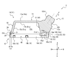
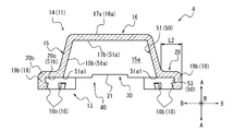
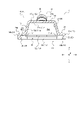
- 5 (a) and 5 (b) are cross-sectional views taken along the line III-III. It is sectional drawing of the heating tool in the state of use shown in FIG. It is sectional drawing which shows the state in the process of attaching a thermal body to the ear wearer shown in FIG.
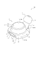
- FIGS. 1 and 2 are perspective views showing a heating tool 100 as an embodiment of the heating device according to the present invention.
- the heating tool 100 includes a heating body 2, a cover member 3, and an ear wearing tool 4 as an embodiment of the ear wearing tool according to the present invention.
- FIG. 1 is an exploded perspective view of the heating tool 100.
- FIG. 2 is a perspective view of the heating tool 100 in a used state.
- the heating device 100 may be distributed on the market in a state where the heating body 2, the cover member 3, and the ear mounting device 4 are separately disassembled (see FIG. 1), and the heating device 2 and the ear mounting device 4 may be distributed with respect to the ear mounting device 4. It may be distributed on the market in a used state (see FIG. 2) with the cover member 3 attached. Further, each of the heating body 2, the cover member 3 and the ear wearing tool 4 constituting the heating device 100 may be separately distributed on the market.
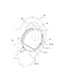
- FIG. 3 is a diagram showing a state in which the heating device 100 in the used state shown in FIG. 2 is attached to the user's ear.
- the heating device 100 of the present embodiment is used by being worn on the ear.
- a predetermined portion of the ear can be heated by the heating body 2 while being worn on the user's ear.
- dizziness symptoms such as dizziness, tinnitus, headache, and stiff shoulders.
- the internal parasympathetic nerves are stimulated by the heating, and a relaxing effect can be obtained.
- the cover member 3 is inserted into the external ear hole EA, which is a so-called ear hole, and the ear fitting 4 is fitted into the auricle CA of the auricle AU. By doing so, it can be fixed to the ear.
- the heating device 100 of the present embodiment is in a state of being attached to the ear.
- the heating tool 100 may be worn on the ear, and the fixing method thereof is not particularly limited.
- the heating tool 100 may be fixed to the ear only by being inserted into the external ear canal EA and closely fitted to the inner surface of the external ear canal EA, for example.
- the heating tool 100 may be fixed to the ear only by being fitted into the concha CA and closely fitted to the inner surface of the concha CA. Further, the heating device 100 may be fixed to the ear by sandwiching any part of the auricle AU other than the auricle CA.
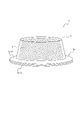
- FIG. 4 is a diagram showing a single body of the thermal body 2.
- the thermal body 2 of the present embodiment is a disposable body warmer.
- the thermal body 2 is sealed in a film bag that shuts off air before use.
- the thermal body 2 before use may be sealed in the film bag by itself, or may be sealed in the film bag together with the ear wearer 4 in a state of being attached to the ear wearer 4 in advance. good.
- the heat-generating body 2 of the present embodiment includes a heat-generating composition 5 that causes a chemical reaction accompanied by heat generation when it comes into contact with air, and an accommodating body 6 that houses the heat-generating composition 5.
- the exothermic composition 5 includes, for example, an oxidizable metal (iron powder, etc.), activated carbon, carbon black, a water retention agent (wood powder, vermiculite, diatomaceous earth, pearlite, silica gel, alumina, water-absorbent resin, etc.), a metal salt (salt, etc.). ), Water, etc. are included as appropriate.
- the housing 6 of the present embodiment includes a first sheet 6a and a second sheet 6b that sandwich and house the heat generating composition 5. The peripheral portions of the first sheet 6a and the second sheet 6b are bonded to each other by, for example, adhesion, welding, etc., with the heat generating composition 5 sandwiched between the first sheet 6a and the second sheet 6b.
- the heat-generating composition 5 is sandwiched between the first sheet 6a and the second sheet 6b so that the first sheet 6a has a hat shape and the second sheet 6b has a circular flat shape.
- the thermal body 2 of the present embodiment is attached to the ear wearer 4 so that the first sheet 6a is covered with the ear wearer 4 (see FIG. 9).
- the thermal body 2 of the present embodiment is attached to the ear fitting 4 with the second sheet 6b exposed to the outside (see FIGS. 3 and 9).
- the air permeability of the first sheet 6a is higher than the air permeability of the second sheet 6b. By doing so, it is possible to suppress heat dissipation through the second sheet 6b exposed to the outside in a state where the thermal body 2 is attached to the ear fitting 4.
- the first sheet 6a is preferably a moisture permeable sheet
- the second sheet 6b is preferably a non-breathable sheet.
- the first sheet 6a may be made of, for example, a highly breathable material, or may be made of a material in which ventilation holes are appropriately formed.
- Examples of the material constituting the first sheet 6a include woven fabrics, non-woven fabrics, synthetic resins, rubbers, elastomers, and the like.
- the second sheet 6b may be made of, for example, a material having low air permeability. Examples of the material constituting the second sheet 6b include a synthetic resin, a laminate of the synthetic resin and a woven fabric or a non-woven fabric, and the like.
- Examples of the fiber material constituting the highly breathable woven fabric or non-woven fabric include synthetic fibers such as nylon, vinylon, polyester, rayon, acrylic, polyethylene, polypropylene, acetate, polyvinyl chloride, and polybutylene terephthalate, cotton, and linen.
- Examples include natural fibers such as silk and paper, and mixed fibers of synthetic fibers and natural fibers. These fiber materials may be used alone or in combination of two or more.
- the second sheet 6b may be, for example, a resin film made of the resin material exemplified in the above-mentioned fiber material.
- the first sheet 6a may be a resin film similar to the second sheet 6b in which ventilation holes are appropriately formed.
- the thermal body 2 of the present embodiment has a configuration including, but is not limited to, a heat generating composition 5 that causes a chemical reaction accompanied by heat generation when it comes into contact with air.
- the thermal body 2 may be configured to be capable of storing heat for a predetermined time, and may be used by being heated in a microwave oven, for example. Further, the thermal body 2 may be one that utilizes the heat of solidification of an aqueous sodium acetate solution that is in a supercooled state at room temperature, for example.
- the accommodating body 6 that encloses the heat generating composition 5 is composed of the first sheet 6a and the second sheet 6b, but is not limited to this configuration.
- the structure of the housing 6 is not particularly limited as long as it is configured to house and hold the heat generating composition 5 so as to correspond to the structure of the ear fitting 4.
- the portion of the thermal body 2 of the present embodiment in which the heat generating composition 5 is housed is referred to as a main body portion 2a of the thermal body 2.
- the main body 2a of the present embodiment has a substantially truncated cone-shaped outer shape, but the outer shape is not particularly limited.
- the portion of the thermal body 2 of the present embodiment that protrudes from the main body portion 2a is referred to as a held portion 2b.
- the held portion 2b of the present embodiment is a flange portion that protrudes outward in the radial direction from the end portion on the large diameter side of the main body portion 2a having a truncated cone shape.
- the held portion 2b of the present embodiment is composed of peripheral portions of the first sheet 6a and the second sheet 6b.
- the cover member 3 is configured to be attachable to an insertion portion 12 described later in the ear fitting 4. More specifically, the cover member 3 of the present embodiment is folded back from the mounting cylinder portion 3a (see FIG. 9) into which the insertion portion 12 of the ear fitting 4 is internally fitted and the tip of the mounting cylinder portion 3a.
- the outer cylinder portion 3b which is continuous with the outer cylinder portion 3b, is provided.
- the insertion portion 12 of the ear fitting 4 is inserted into the inside through the opening on the base end side of the mounting cylinder portion 3a of the cover member 3.
- the insertion portion 12 can hold the mounting cylinder portion 3a by being in close contact with the inner surface of the mounting cylinder portion 3a.
- the insertion portion 12 of the ear fitting 4 of the present embodiment includes the annular convex portion 12b1.
- the annular convex portion 12b1 of the insertion portion 12 fits into the annular recess 3a1 (see FIG. 9) provided on the inner surface of the mounting cylinder portion 3a. This makes it possible to improve the holdability of the cover member 3 by the insertion portion 12.
- the outer cylinder portion 3b covers the radial outside of the mounting cylinder portion 3a.
- An annular space is partitioned between the mounting cylinder portion 3a and the exterior cylinder portion 3b. Therefore, when the outer cylinder portion 3b is inserted into the outer ear hole EA as shown in FIG. 3, it is pressed against the inner surface of the outer ear hole EA, so that the outer cylinder portion 3b is directed inward in the radial direction so as to approach the outer surface of the mounting cylinder portion 3a. While elastically deforming, it comes into close contact with the inner surface of the external ear canal EA.
- the cover member 3 is fitted into the external ear canal EA so as to be in close contact with the inner surface of the external ear canal EA, and the fixing property of the heating tool 100 by the external ear canal EA is improved. Can be enhanced. Further, by using the cover member 3, the external ear canal EA can be closed and the sound insulation can be improved. As a result, external noise and the like can be blocked, and a user wearing the heating device 100 can easily relax.
- the material constituting the cover member 3 is not particularly limited, and examples thereof include synthetic resins including rubber, elastomers, soft resins, and hard resins.
- synthetic resin for example, polypropylene (PP), polyethylene (PE), polyethylene terephthalate (PET) and the like can be used.
- the mounting cylinder portion 3a and the exterior cylinder portion 3b are integrally formed of the same material, but may be formed of different materials.
- the cover member 3 may have a structure in which a material such as metal or carbon is mixed with a base material such as rubber, elastomer, or synthetic resin.
- the cover member 3 may be made of a heat conductive resin.
- the ear fitting 4 is configured so that the above-mentioned thermal body 2 and cover member 3 can be attached. Further, the ear wearer 4 is configured to be wearable to the ear together with the attached thermal body 2 and the cover member 3.
- the ear wearing tool 4 can be attached to the ear means that not only the ear wearing tool 4 itself is directly fixed to the ear, but also the ear wearing tool 4 is fixed to the ear, for example, the cover member 3. It also means that it is indirectly fixed to the ear via another member such as.
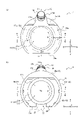
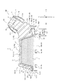
- FIG. 5A is a top view of the ear wearer 4 alone as viewed from the top side.
- FIG. 5B is a bottom view of the ear wearer 4 alone as viewed from the bottom surface side.
- the "upper surface” of the ear fitting 4 means a surface located on the auricle AU (see FIG. 3) side in a state where the ear fitting 4 is attached to the ear.
- the "lower surface” of the ear fitting 4 means a surface opposite to the upper surface.
- FIG. 6 is a cross-sectional view of the ear wearer 4 at the position of line II shown in FIGS. 5 (a) and 5 (b).
- FIG. 7 is a cross-sectional view of the ear wearer 4 at the position of the line II-II shown in FIGS. 5 (a) and 5 (b).
- FIG. 8 is a cross-sectional view of the ear wearer 4 at the position of line III-III shown in FIGS. 5 (a) and 5 (b).
- the details of the ear fitting 4 will be described with reference to FIGS. 1 to 3 and FIGS. 5 to 8.
- the ear fitting 4 of the present embodiment includes a contact portion 11, an insertion portion 12, a holding portion 13, and a connecting flange portion 20.
- the contact portion 11 comes into contact with a predetermined portion of the pinna AU in a state where the ear wearer 4 is attached to the ear (see FIG. 3).
- the predetermined portion of the pinna AU to which the contact portion 11 comes into contact with the ear wearer 4 is not particularly limited in the state of being worn on the ear (see FIG. 3).
- the contact portion 11 of the present embodiment is composed of a fitting portion 14 that can be fitted into the auricle CA of the auricle AU.
- the fitting portion 14 is configured to be fitted into the auricle CA so as to come into contact with the inner surface of the auricle CA as a predetermined portion of the auricle AU. More specifically, the fitting portion 14 as the contact portion 11 of the present embodiment is fitted into the concha CA so as to come into contact with the inner surface of the concha cavity among the inner surfaces of the concha CA. It is configured.
- the predetermined portion of the auricle AU to which the contact portion 11 comes into contact is not particularly limited, but the contact portion 11 is fitted into the auricle CA as in the present embodiment, so that the auricle CA can be fitted. It is preferable that the fitting portion 14 is in contact with the inner surface, and it is particularly preferable that the fitting portion 14 is in contact with the inner surface of the auricular cavity.
- the extending direction of the fitting portion 14 will be referred to as “height direction A of the fitting portion 14” or simply “height direction A”.
- the fitting portion 14 of the present embodiment has a substantially truncated cone-shaped outer shape. Therefore, the height direction A of the fitting portion 14 of the present embodiment is the central axis direction of the annular side wall portion 15 (see FIG. 1 and the like) described later. Further, hereinafter, for convenience of explanation, the direction from the base end side to the tip end side of the fitting portion 14 in the height direction A of the fitting portion 14 may be simply referred to as “upper side”.
- the direction from the tip end side to the base end side of the fitting portion 14 may be simply described as "lower side".
- the upper side of the present embodiment means one end side of the annular side wall portion 15 (see FIG. 1 and the like) to which the top plate portion 16 (see FIG. 1 and the like) to be described later is connected.
- the lower side of the present embodiment means the other end side of the annular side wall portion 15 opposite to the one end side on which the top plate portions 16 are connected.
- the fitting portion 14 of the present embodiment internally partitions an internal space 15a capable of accommodating a heating body 2 that heats the inner surface of the concha CA through the fitting portion 14. .
- the fitting portion 14 of the present embodiment includes a convex surface that contacts the inner surface of the concha CA and a concave surface that partitions the internal space 15a on the back side of the convex surface.
- the fitting portion 14 of the present embodiment includes an annular side wall portion 15 and a top plate portion 16.
- the annular side wall portion 15 is configured to be fitable to the concha CA.
- the annular side wall portion 15 of the present embodiment can be fitted so as to be sandwiched between the inner side surfaces of the concha CA.
- the annular side wall portion 15 of the present embodiment can be fitted so as to be sandwiched between the inner surface of the concha cavity of the inner surface of the concha CA.
- the annular side wall portion 15 internally partitions an internal space 15a that can accommodate the main body portion 2a (see FIG. 4) of the thermal body 2.
- the top plate portion 16 is connected to one upper end (hereinafter, referred to as “upper end”) of the annular side wall portion 15.
- the upper end of the internal space 15a of the annular side wall portion 15 is closed by the top plate portion 16.
- the internal space 15a of the present embodiment is a truncated cone-shaped space partitioned by the annular side wall portion 15 and the top plate portion 16.
- the top plate portion 16 has a bottom contact surface 16a that can come into contact with the bottom surface of the concha CA in a state where the annular side wall portion 15 is fitted to the concha CA. More specifically, the bottom contact surface 16a of the present embodiment is configured to be able to contact the bottom surface of the concha cavity among the bottom surfaces of the concha CA.
- the bottom contact surface 16a of the top plate portion 16 of the present embodiment is composed of a top plate upper surface 17a opposite to the top plate lower surface 17b facing the internal space 15a of the top plate portion 16.
- the outer surface of the annular side wall portion 15 of the fitting portion 14 of the present embodiment constitutes a lateral contact surface that can be contacted with the inner surface of the earpiece CA.
- the above-mentioned thermal body 2 is attached to the ear fitting 4 by accommodating the main body 2a in the internal space 15a.
- the main body portion 2a of the thermal body 2 is an open end that is a lower end (hereinafter, referred to as “lower end”) on the side opposite to the upper end that is connected to the top plate portion 16 of the annular side wall portion 15. Therefore, it can be accommodated in the internal space 15a.
- the main body portion 2a of the thermal body 2 does not contact the annular side wall portion 15 and the top plate portion 16 in the internal space 15a, and is separated from the annular side wall portion 15 and the top plate portion 16 by a gap X (see FIG. 9). It is housed in the same state. The details will be described later (see FIG. 9).
- the outer shape of the fitting portion 14 of the present embodiment is a truncated cone shape, but the outer shape is not particularly limited.
- the outer shape of the fitting portion 14 may be, for example, a cylindrical shape.
- the outer shape of the fitting portion 14 may be, for example, a shape corresponding to the inner surface of the instep CA. Therefore, the annular side wall portion 15 in the fitting portion 14 is not limited to the tapered tubular shape of the present embodiment.
- the annular side wall portion 15 may have a cylindrical shape having a uniform inner diameter and outer diameter regardless of the position in the central axial direction.
- the outer surface of the annular side wall portion 15 has a tapered shape that tapers from the lower end on the side opposite to the upper end where the top plate portions 16 are connected toward the upper end where the top plate portions 16 are connected, as in the present embodiment. Is preferable. By doing so, it becomes easy to fit the fitting portion 14 into the instep CA.
- the annular side wall portion 15 does not have to have a circular outer shape in a cross section orthogonal to the height direction A, and the outer cross section may have an endless shape corresponding to the inner surface of the concha CA.
- the top plate portion 16 of the present embodiment is configured by a circular flat flat plate portion that closes the upper end of the tapered tubular annular side wall portion 15, but is not limited to this configuration.
- the top plate portion 16 is preferably configured so that the area where the bottom contact surface 16a contacts the bottom surface of the concha CA can be increased. Therefore, the top plate portion 16 may be configured by, for example, a curved plate portion curved in a dome shape so that the bottom contact surface 16a is a convex surface.
- the internal space 15a of the present embodiment is a space having a substantially truncated cone shape, but the shape of the internal space 15a is not particularly limited.
- the internal space 15a of the present embodiment may be configured so that a part of the heating body 2 can be accommodated and the auricle AU can be heated through the fitting portion 14.
- the main body portion 2a of the thermal body 2 is housed in the internal space 15a, so that the main body portion 2a is covered with the annular side wall portion 15 and the top plate portion 16.
- the insertion portion 12 protrudes from the fitting portion 14.
- the insertion portion 12 is configured to be insertable into the external ear canal EA (see FIG. 3) together with the cover member 3 to be attached.
- the insertion portion 12 of the present embodiment projects outward from the fitting portion 14 in a plan view (see FIG. 5A) when viewed in the height direction A of the fitting portion 14. More specifically, the insertion portion 12 of the present embodiment projects from the annular side wall portion 15 of the fitting portion 14 to the outside of the annular side wall portion 15 in the radial direction B.
- the radial direction B of the annular side wall portion 15 may be simply referred to as “diameter direction B”.
- the insertion portion 12 of the present embodiment has a base end portion 12a connected to the annular side wall portion 15 and a tip end portion 12b connected to the base end portion 12a and inserted into the mounting cylinder portion 3a (see FIG. 9) of the cover member 3. And.
- the tip portion 12b has a substantially columnar outer shape.
- the central axial direction C which is the extending direction of the tip portion 12b, is inclined with respect to the height direction A of the fitting portion 14.
- the tip portion 12b can be inserted into the mounting cylinder portion 3a of the cover member 3 so as to push the mounting cylinder portion 3a outward in the radial direction. As a result, the outer surface of the tip portion 12b is in close contact with the inner surface of the mounting cylinder portion 3a.
- the cover member 3 is held by the insertion portion 12 of the ear wearer 4. Further, in addition to the close contact between the outer cylinder portion 3b and the inner surface of the outer ear hole EA, the outer surface of the tip portion 12b and the inner surface of the mounting cylinder portion 3a can further close the outer ear hole EA, and the sound insulation by the heating tool 100 can be achieved. Can be further enhanced.
- the tip portion 12b of the present embodiment includes an annular convex portion 12b1 protruding outward in the radial direction.
- the annular convex portion 12b1 of the tip portion 12b is provided with the annular recess 3a1 on the inner surface of the mounting cylinder portion 3a (see FIG. 9). ). This makes it difficult for the mounting cylinder portion 3a to come off from the tip portion 12b. Therefore, the holdability of the cover member 3 by the insertion portion 12 can be improved.
- the insertion portion 12 of the present embodiment is formed separately from the cover member 3 so that the cover member 3 described above can be attached, but may be integrally formed. Therefore, the tip portion 12b of the insertion portion 12 of the present embodiment may be formed so as to be integrally connected with the mounting cylinder portion 3a of the cover member 3, for example.
- the ear fitting 4 of the present embodiment includes an insertion portion 12, but is not limited to this configuration.
- the ear fitting 4 of the present embodiment is configured to be fixed to the ear by being in close contact with the inner surface of the external ear canal EA.
- the heating device 100 preferably includes an insertion portion 12 that can be inserted into the external ear canal EA.
- the heating tool 100 further includes a cover member 3 attached to the insertion portion 12 in order to enhance the adhesion of the external ear hole EA to the inner surface. By doing so, the relaxing effect due to the sound insulation can be further enhanced.
- the insertion portion 12 of the present embodiment is integrally formed with the fitting portion 14, it may be formed separately from the fitting portion 14 and detachably attached to the fitting portion 14.
- the holding portion 13 can hold the thermal body 2 that heats a predetermined portion of the pinna AU through the fitting portion 14 as the contact portion 11.
- the thermal body 2 held by the holding portion 13 of the present embodiment can heat the inner surface of the auricle CA as a predetermined portion of the auricle AU through the fitting portion 14.
- the holding portion 13 can hold the thermal body 2 in a state of being separated from the fitting portion 14 by a gap X (see FIG. 9). By doing so, it is possible to suppress a rapid temperature rise of the fitting portion 14 due to the heating body 2 as compared with a configuration in which the fitting portion 14 and the heating body 2 are in contact with each other without the gap X. Therefore, it is possible to suppress burns on the inner surface of the auricle CA of the auricle AU that comes into contact with the fitting portion 14.
- the holding portion 13 of the present embodiment has a support portion 18 that supports the heating body 2 from below, and the heating body 2 moves in a direction orthogonal to the height direction A.
- a regulation wall portion 19 for regulating is provided.
- the support portion 18 of the present embodiment has a flat plate shape extending in a direction orthogonal to the height direction A below the lower end of the fitting portion 14.
- a support plate portion 18a of the above, and a support protrusion portion 18b protruding inward in the radial direction B from the regulation wall portion 19 are provided.
- the held portion 2b of the thermal body 2 is supported from below by the support plate portion 18a and the support protrusion portion 18b in a state where the main body portion 2a is housed in the internal space 15a. Therefore, the support plate portion 18a and the support protrusion portion 18b are provided at positions that do not overlap with the internal space 15a in the height direction A. More specifically, the support plate portion 18a and the support protrusion portion 18b of the support portion 18 of the present embodiment are provided at positions outside the radial direction B from the internal space 15a.
- the regulation wall portion 19 is connected to the outer side of the support portion 18 in the radial direction B and extends toward the upper side in the height direction A. More specifically, as shown in FIGS. 6 to 8, the regulation wall portion 19 of the present embodiment is connected to the outer side of the support plate portion 18a in the radial direction B and extends toward the upper side in the height direction A.
- a first regulation wall portion 19a and a second regulation wall portion 19b that is connected to the outer side of the support protrusion 18b in the radial direction B and extends toward the upper side in the height direction A are provided.
- the first regulated wall portion 19a and the second regulated wall portion 19b are of the held portion 2b. It is located on the outer side of the radial direction B. Therefore, in a state where the main body portion 2a is housed in the internal space 15a and the held portion 2b is supported from below by the support plate portion 18a and the support protrusion portion 18b, the held portion 2b of the thermal body 2 is supported. The movement in the direction orthogonal to the height direction A is restricted by the first regulation wall portion 19a and the second regulation wall portion 19b.
- the holding portion 13 of the present embodiment is orthogonal to the lower side of the held portion 2b of the heating body 2 in the height direction A and the height direction A by the supporting portion 18 and the regulating wall portion 19.
- the thermal body 2 can be held.
- the movement of the held portion 2b of the thermal body 2 on the upper side in the height direction A is restricted by the lower end of the fitting portion 14 described above.
- a collar that protrudes outward in the radial direction B from the opening end that is the lower end of the fitting portion 14 and connects the fitting portion 14 and the second regulating wall portion 19b of the holding portion 13.
- a connecting flange portion 20 is provided as a portion.
- the connecting flange portion 20, together with the lower end of the fitting portion 14, restricts the movement of the held portion 2b of the thermal body 2 on the upper side in the height direction A.
- the ear fitting 4 may have a portion connecting the fitting portion 14 and the holding portion 13, and the configuration thereof is not limited to the connecting flange portion 20 of the present embodiment. Therefore, the movement of the held portion 2b of the thermal body 2 on the upper side in the height direction A may be restricted by the lower end of the fitting portion 14 described above, and the regulation by the connecting flange portion 20 is not essential.
- the fitting portion 14 is connected to the second regulation wall portion 19b via the connecting flange portion 20.
- a support protrusion 18b projects from the second regulation wall portion 19b to the inside in the radial direction B.
- the second regulation wall portion 19b is connected to the support plate portion 18a.
- the first regulation wall portion 19a is connected to the outer edge of the support plate portion 18a.
- the fitting portion 14 and the holding portion 13 are integrally formed via the connecting flange portion 20, but at least one of the holding portion 13, the fitting portion 14 and the connecting flange portion 20 is formed as a separate body. , May be joined by adhesion, welding or the like.
- the support plate portion 18a of the present embodiment faces the lower surface, which is the lower surface of the base end portion 12a of the above-mentioned insertion portion 12, with a gap in the height direction A. ..
- the held portion 2b of the thermal body 2 can be inserted from the inside to the outside in the radial direction B.
- the first regulation wall portion 19a extends upward from the outer edge portion outside the radial direction B of the support plate portion 18a and is connected to the base end portion 12a of the insertion portion 12.
- the ear fitting 4 of the present embodiment includes a connecting collar portion 20 as a flange portion in addition to the contact portion 11, the insertion portion 12, and the holding portion 13.
- the connecting flange portion 20 of the present embodiment is connected to the fitting portion 14 as the contact portion 11. More specifically, the connecting flange portion 20 of the present embodiment projects outward from the lower end of the fitting portion 14 in the radial direction B, and connects the fitting portion 14 and the second regulating wall portion 19b of the holding portion 13. As shown in FIG.
- the outer edge of the connecting flange portion 20 is the second regulating wall portion 19b of the regulating wall portion 19 that covers the periphery of the held portion 2b of the thermal body 2 in the housed state (FIG. 5).
- a free end portion 20a not connected to the second regulated wall portion 19b of the regulated wall portion 19 is provided.
- the length L1 in the radial direction B of the connecting flange portion 20 at the position of the free end portion 20a is shorter than the length L2 in the radial direction B of the connecting flange portion 20 at the position of the wall connecting end portion 20b.
- a ventilation groove 21 extending from the position of the free end portion 20a to the internal space 15a is formed on the lower surface of the connecting flange portion 20. Therefore, in the present embodiment, the ventilation groove 21 connects the ventilation path 30 from the position of the free end portion 20a of the connecting flange portion 20 to the recess provided at the opening end which is the lower end of the fitting portion 14 and communicates with the internal space 15a. It is partitioned. Therefore, even if the main body 2a of the thermal body 2 is accommodated in the internal space 15a and the held portion 2b of the thermal body 2 is in contact with the opening end of the fitting portion 14 and the connecting flange portion 20. Air can be taken into the internal space 15a through the ventilation groove 21.
- the ventilation passage 30 is partitioned by the ventilation groove 21, but the ventilation passage 30 is not limited to the configuration of the present embodiment.
- the connecting flange portion 20 of the present embodiment is in the circumferential direction D of the fitting portion 14 (in the present embodiment, the same direction as the circumferential direction of the annular side wall portion 15, and hereinafter, simply In the "circumferential direction D"), it is not provided at the positions on both sides of the insertion portion 12. Therefore, the ear fitting 4 of the present embodiment is configured so that the upper surface of the support plate portion 18a can be visually recognized in the top view shown in FIG. 5A.
- the held portion 2b is inserted between the lower surface of the base end portion 12a of the insertion portion 12 and the upper surface of the support plate portion 18a from the inside to the outside in the radial direction B.
- the holding portion 2b of the thermal body 2 is the lower surface of the base end portion 12a of the insertion portion 12 and the support plate portion 18a. Whether or not it is properly inserted between it and the upper surface can be visually recognized from the outside.
- the ear fitting 4 of the present embodiment includes a connecting flange portion 20 that protrudes outward in the radial direction B from the opening end that is the lower end of the fitting portion 14 in order to connect the fitting portion 14 and the holding portion 13.
- the configuration is not limited to the configuration of the connecting flange portion 20 of the present embodiment.
- the flange-shaped held portion 2b of the thermal body 2 moves so as to be tilted with respect to the height direction A while the main body portion 2a of the thermal body 2 is accommodated in the internal space 15a. It can be suppressed. As a result, the main body 2a of the thermal body 2 does not easily come off from the internal space 15a. Therefore, the positional stability of the thermal body 2 in the state where the held portion 2b of the thermal body 2 is held by the holding portion 13 can be further improved.
- the material constituting the ear fitting 4 is not particularly limited, and examples thereof include synthetic resins including rubber, elastomers, soft resins, and hard resins. More specifically, polypropylene (PP), polyethylene (PE), polyethylene terephthalate (PET), elastomer and the like can be mentioned.
- the material constituting the ear fitting 4 may be a material having high thermal conductivity in terms of efficiently transferring the heat of the thermal body 2 to the pinna AU (see FIG. 3). Examples of such a material include those in which a material having a high thermal conductivity such as metal and carbon is mixed with a base material such as rubber, an elastomer, and a synthetic resin to increase the thermal conductivity. Further, a heat conductive resin having a high thermal conductivity may be used.
- FIG. 9 is a cross-sectional view of the heating tool 100 in a used state in which the heating body 2 and the cover member 3 are attached to the ear wearing tool 4.
- FIG. 9 shows a cross section at the same position as the position of line II in FIG. 5 in a state where the heating body 2 and the cover member 3 are attached to the ear fitting 4.
- FIG. 10 is a cross-sectional view taken at the same position as FIG. 9, showing a state in which the thermal body 2 is being attached to the ear wearing tool 4.
- the holding portion 13 of the present embodiment can hold the heating body 2 that heats the inner surface of the auricle CA (see FIG. 3) of the auricle AU (see FIG. 3) through the fitting portion 14. Is.
- the support portion 18 and the regulation wall portion 19 of the holding portion 13 are the held portions of the heating body 2 while the main body portion 2a of the heating body 2 is housed in the internal space 15a. Hold 2b.
- the holding portion 13 limits the movement of the heat body 2 with respect to the ear wearer 4 within a predetermined range so that the heat body 2 does not separate from the ear wearer 4. That is, the configuration of the holding portion 13 is not limited to the configuration in which the heating body 2 is held so as not to move with respect to the ear fitting 4.
- the holding portion 13 of the present embodiment holds the held portion 2b of the thermal body 2 so as to be movable within a predetermined range in the height direction A.
- the upper surface of the held portion 2b is fitted into the holding portion 14 from a position where the lower surface of the held portion 2b is in contact with and supported by the support plate portion 18a and the support protrusion portion 18b.
- the thermal body 2 is held so that the thermal body 2 can move in the height direction A within the range up to the position where it contacts the lower end of the joint portion 20 and the lower surface of the connecting flange portion 20.
- the uppermost holding position of the heating body 2 is such that the upper surface of the held portion 2b of the heating body 2 is in contact with the opening end which is the lower end of the fitting portion 14 and the lower surface of the connecting flange portion 20. Shows.
- the holding portion 13 of the present embodiment holds the held portion 2b of the thermal body 2 in a state of being immovable in a direction orthogonal to the height direction A.
- the first regulation wall portion 19a and the second regulation wall portion 19b of the regulation wall portion 19 are around the held portion 2b of the heating body 2 in the direction orthogonal to the height direction A. Is located. Therefore, the first regulation wall portion 19a and the second regulation wall portion 19b of the regulation wall portion 19 come into contact with the outer edge of the held portion 2b of the heat body 2, so that the heat body is orthogonal to the height direction A.
- the movement of 2 is regulated.
- the holding portion 13 may hold the held portion 2b of the thermal body 2 so as to be movable within a predetermined range in the direction orthogonal to the height direction A.
- the holding portion 13 may hold the thermal body 2 in a state of being separated from the fitting portion 14 by a gap X.
- the holding portion 13 movably holds the thermal body 2 within a predetermined range as in the present embodiment, the thermal body 2 at an arbitrary position within the movable predetermined range is fitted.
- the space X may be separated from the portion 14 so as to be separated from the portion 14.
- FIG. 9 shows a state in which the heating body 2 is in the uppermost holding position, but even in this state, the main body portion 2a of the heating body 2 of the present embodiment is the annular side wall portion 15 of the fitting portion 14. And the state of being separated from the top plate portion 16 by the gap X is maintained. By doing so, it is possible to suppress a rapid temperature rise of the fitting portion 14 due to the heating body 2 and to prevent burns from occurring on the inner surface of the auricle CA of the auricle AU to which the fitting portion 14 contacts.
- the holding portion 13 of the present embodiment has an internal space inside the annular side wall portion 15 from the top plate lower surface 17b side, which is the back surface side of the top plate upper surface 17a, where the heating body 2 is the bottom contact surface 16a of the top plate portion 16.
- the thermal body 2 is held in a state of being housed in 15a.
- the holding portion 13 is configured to hold the heating body 2 housed in the internal space 15a in the annular side wall portion 15 as described above, so that the heating body 2 can be easily attached to the ear fitting 4. Can be done.
- the main body portion 2a of the thermal body 2 is an internal space inside the annular side wall portion 15 from the top plate lower surface 17b side of the top plate portion 16.
- the held portion 2b protruding from the main body portion 2a of the thermal body 2 is held.
- the thermal body 2 can be easily attached to the ear fitting 4.
- the held portion 2b of the thermal body 2 comes into contact with the lower end of the annular side wall portion 15 which is the lower end of the fitting portion 14, so that the amount of pushing of the main body portion 2a into the annular side wall portion 15 can be regulated. ..
- a gap X can be easily secured between the main body portion 2a of the thermal body 2 and the top plate portion 16.
- the flange portion as the held portion 2b of the heating body 2 is placed in the gap between the support plate portion 18a and the insertion portion 12 in the radial direction B.
- the main body portion 2a of the thermal body 2 is accommodated in the inner space 15a inside the annular side wall portion 15 from the lower end side of the annular side wall portion 15 while being inserted from the inside to the outside.
- the main body portion 2a is housed in the annular side wall portion 15, except for the portion of the held portion 2b of the thermal body 2 that is inserted into the gap between the support plate portion 18a and the insertion portion 12, the support protrusion portion 18b. That is, it is completed when the held portion 2b is held by the holding portion 13.
- the holding portion 13 of the present embodiment holds the heating body 2 in a state where the main body portion 2a of the heating body 2 is covered with the fitting portion 14. In this way, when the fitting portion 14 covers the main body portion 2a of the heating body 2, the heat generated in the main body portion 2a is not consumed due to the heating of the fitting portion 14, and is wasted. Can be suppressed.
- the fitting portion 14 covers at least the surface of the heating portion of the heating body 2 that heats the fitting portion 14. Therefore, like the fitting portion 14 of the present embodiment, the surface of the main body portion 2a as the heating portion for heating the fitting portion 14 of the heating body 2 is covered, and the held portion 2b which is not the heating portion is covered. It may be a configuration that does not cover.
- the accommodation space 40 means a space in which the thermal body 2 is located in a state where the thermal body 2 is attached to the ear fitting 4.
- the "space in which the thermal body 2 is located" referred to here is a range in which the thermal body 2 can be moved within a predetermined range when the thermal body 2 is movably held with respect to the ear fitting 4 as in the present embodiment.
- the accommodation space 40 of the present embodiment includes an internal space 15a of the fitting portion 14 that can accommodate the main body portion 2a of the thermal body 2. Further, the accommodation space 40 of the present embodiment includes a space inside the radial direction B with respect to the first regulation wall portion 19a and the second regulation wall portion 19b that can accommodate the held portion 2b of the thermal body 2. Further, the accommodation space 40 of the present embodiment is above the support plate portion 18a and the support projection portion 18b of the support portion 18 in the height direction A capable of accommodating the held portion 2b of the thermal body 2. , The lower end of the fitting portion 14, the lower surface of the insertion portion 12, and the space below the lower surface of the connecting flange portion 20.
- the ward screen 50 for partitioning the accommodation space 40 As shown in FIGS. 6 to 9, the ward screen 50 includes a hat-shaped surface 51, a flange facing surface 52, and a surrounding surface 53.
- the hat-shaped surface 51 includes a concave surface 51a formed on the back side of the contact surface in contact with the pinna AU, and a flange surface 51b extending from the open end 51a1 of the concave surface 51a.
- the contact surface that comes into contact with the pinna AU is, for example, the upper surface 17a of the top plate as the bottom contact surface 16a of the fitting portion 14.
- the concave surface 51a of the present embodiment is a surface for partitioning the internal space 15a of the fitting portion 14. More specifically, the concave surface 51a of the present embodiment is composed of an inner surface 15b of the annular side wall portion 15 and a top plate lower surface 17b of the top plate portion 16. Further, the flange surface 51b of the present embodiment is composed of a lower surface 12a1 of the insertion portion 12 and a lower surface 20c of the connecting flange portion 20.
- the flange facing surface 52 is arranged so as to face each other with a gap in the axial direction of the predetermined portion 60, which is a part of the flange surface 51b, and the concave surface 51a.
- the "axial direction of the concave surface 51a” means a direction orthogonal to the plane including the open end 51a1 of the concave surface 51a. That is, the axial direction of the concave surface 51a of the present embodiment is the same as the height direction A of the fitting portion 14.
- the axial direction of the concave surface 51a is simply referred to as “height direction A”.
- a part of the thermal body 2 can be inserted between the predetermined portion 60 of the flange surface 51b and the flange facing surface 52 from the inside to the outside in the radial direction of the concave surface 51a.
- the "diametrical direction of the concave surface 51a” means the radial direction of the circle formed by the open end 51a1 of the concave surface 51a. That is, the radial direction of the concave surface 51a of the present embodiment is the same as the radial direction B of the annular side wall portion 15.
- the radial direction of the concave surface 51a is simply referred to as “diameter direction B”.
- the flange facing surface 52 of the present embodiment is the upper surface 18a1 of the support plate portion 18a. Therefore, the predetermined portion 60, which is a part of the flange surface 51b of the present embodiment, is the lower surface 12a1 of the insertion portion 12.
- the predetermined portion 60 of the flange surface 51b is a portion 60a located outside the radial direction B from the inner end in the radial direction B and located on the bottom side of the concave surface 51a in the height direction A from the opening end 51a1 of the concave surface 51a.
- a portion 60a located on the upper side is provided.
- the inner end of the lower surface 12a1 of the insertion portion 12 of the present embodiment in the radial direction B is the open end 51a1 of the concave surface 51a.
- the lower surface 12a1 of the insertion portion 12 of the present embodiment is composed of an inclined surface that inclines toward the upper side in the height direction A from the inside to the outside in the radial direction B. That is, the lower surface 12a1 of the insertion portion 12 of the present embodiment is an inclined surface having a portion 60a located on the outer side in the radial direction B from the opening end 51a1 of the concave surface 51a which is the inner end and on the upper side in the height direction A from the opening end 51a1. Is.
- the predetermined portion 60 of the flange surface 51b facing the flange facing surface 52 is located outside the radial direction B from the inner end in the radial direction B and above the open end 51a1 of the concave surface 51a in the height direction A.
- the predetermined portion 60 includes the portion 60a, so that the heating body 2 is tilted with respect to the height direction A (the state shown in FIG. 10) to heat the heating body 2.
- a part of the body 2 (held portion 2b in the present embodiment) can be inserted into the gap between the flange facing surface 52 and the predetermined portion 60 of the flange surface 51b. Therefore, another part of the thermal body 2 or all of the rest (main body portion 2a, which is another part in the present embodiment) is also inclined with respect to the height direction A and retracts below the internal space 15a. In this state, it can be moved to a position directly below the internal space 15a.
- the thermal body 2 can be used in the gap between the flange facing surface 52 and the predetermined portion 60 of the flange surface 51b. It can be easily accommodated so as to straddle both of the internal spaces 15a. That is, when the predetermined portion 60 includes the portion 60a, the heating body 2 can be easily attached to the ear wearing tool 4. When the thermal body 2 is removed from the ear attachment 4, the thermal body 2 can be easily removed from the ear attachment 4 by reversing the above-mentioned attachment operation.
- the movable range of the thermal body 2 accommodated in the accommodation space 40 can be reduced. Therefore, it becomes easy to maintain the distance between the thermal body 2 and the concave surface 51a within a desired range.
- the contact surface such as the bottom contact surface 16a located on the opposite side of the concave surface 51a and in contact with the pinna AU can be easily heated to a desired temperature through the concave surface 51a by the heating body 2.
- the auricle AU can be efficiently heated by the heating body 2, and the detachability of the heating body 2 can be improved.
- the specific shape of the portion 60a located above the opening end 51a1 of the concave surface 51a is not particularly limited.
- the portion 60a of the predetermined portion 60 may be formed of, for example, a concave surface recessed upward.
- the predetermined portion 60 of the flange surface 51b is inclined toward the bottom side (upper side in the present embodiment) of the concave surface 51a in the height direction A from the inside to the outside in the radial direction B. It is preferable to have a surface. Further, it is preferable that the portion 60a is composed of the inclined surface.
- a part of the thermal body 2 (held portion 2b in the present embodiment) inserted between the predetermined portion 60 of the flange surface 51b and the flange facing surface 52 is the above-mentioned portion of the predetermined portion 60. It is possible to prevent the 60a from being caught, and it becomes easy to insert it to an appropriate position.
- the length L3 in the radial direction B of the predetermined portion 60 of the flange surface 51b is the radial direction B of the held portion 2b of the thermal body 2 attached to the ear fitting 4.
- the length is L4 or less.
- the predetermined portion 60 is composed of the above-mentioned inclined surface in the entire area in the radial direction B. That is, the portion 60a of the predetermined portion 60 is also composed of the above-mentioned inclined surface.
- the length L1 (see FIGS. 5 and 6) in the radial direction B at the position of the free end portion 20a of the connecting flange portion 20 described above is the radial direction of the held portion 2b of the heating body 2.
- the length of B is smaller than L4. Therefore, as shown in FIGS. 2 and 9, the held portion 2b is exposed to the outside of the free end portion 20a in the radial direction B in a state where the thermal body 2 is attached to the ear fitting 4. Therefore, when the thermal body 2 is removed from the ear wearing tool 4, the portion of the held portion 2b of the thermal body 2 exposed from the free end portion 20a may be grasped and operated. By doing so, the thermal body 2 can be easily removed from the ear fitting 4.
- the flange facing surface 52 is located only on the side opposite to the bottom side of the concave surface 51a in the height direction A from the opening end 51a1 of the concave surface 51a. That is, the flange facing surface 52 is located only below the opening end 51a1 of the concave surface 51a in the height direction A.
- the thermal body 2 After being inserted between the predetermined portion 60 and the flange facing surface 52, the thermal body 2 can be moved to a state where it is not tilted with respect to the height direction A (see FIG. 9). As a result, another part of the thermal body 2 (main body portion 2a in the present embodiment) can be accommodated in the internal space 15a partitioned by the concave surface 51a. In the present embodiment, by moving the thermal body 2 to a state where it is not inclined with respect to the height direction A (see FIG. 9), the held portion 2b of the thermal body 2 gets over the support protrusion portion 18b. As a result, the attachment of the thermal body 2 by the ear wearing tool 4 is completed.
- the "state in which the heating body 2 is inclined with respect to the height direction A” means that the in-plane direction of the held portion 2b of the heating body 2 is the height direction A and the height direction. It means a state of being inclined with respect to a direction orthogonal to A. Further, in the present embodiment, "a state in which the heating body 2 does not incline with respect to the height direction A” means that the in-plane direction of the held portion 2b of the heating body 2 is parallel to the direction orthogonal to the height direction A. Means a state.
- the concave surface 51a of the hat-shaped surface 51 of the present embodiment is configured by the fitting portion 14, but is not limited to this configuration.
- the concave surface 51a may be the back side of the contact surface that comes into contact with a predetermined portion of the auricle AU to be heated.
- the contact surface and the concave surface 51a are formed of the surface of the fitting portion 14 that can be fitted into the earpiece CA.
- the contact surface of the present embodiment is composed of a top plate upper surface 17a (bottom contact surface 16a) and an outer surface (side contact surface) of the annular side wall portion 15, which is the surface of the fitting portion 14. ..
- the concave surface 51a of the present embodiment is composed of a top plate lower surface 17b and an inner surface 15b of the annular side wall portion 15 as the surface of the fitting portion 14. By doing so, it is easy to heat the inner surface of the concha CA by the thermal body 2. By warming the inner surface of the concha CA, the relaxing effect can be enhanced as described above.
- the predetermined portion 60 facing the flange facing surface 52 is composed of the lower surface 12a1 which is the lower surface of the insertion portion 12.
- the predetermined portion 60 of the flange surface 51b may be configured by a portion of the ear fitting 4 different from the insertion portion 12.
- the predetermined portion 60 of the flange surface 51b is formed of the surface of the insertion portion 12 as in the present embodiment.
- the insertion portion 12 can improve the fixing property to the ear and the sound insulation property, and can be easily used as a position where the portion 60a is provided in the predetermined portion 60. Therefore, it is not necessary to provide the predetermined portion 60 as a portion separate from the insertion portion 12, and the configuration of the ear wearing tool 4 can be simplified.
- the ward screen 50 of the present embodiment includes a surrounding surface 53 located on the outer side of the held portion 2b of the thermal body 2 in the radial direction B.
- the surrounding surface 53 is a surface extending downward from the outer edge of the flange surface 51b of the hat-shaped surface 51 to the lower side in the height direction A.
- a part of the surrounding surface 53 is connected to the outer end of the flange facing surface 52 in the radial direction B at the lower end in the height direction A.
- a part of the surrounding surface 53 connects the flange surface 51b and the flange facing surface 52, and is located outside the radial direction B of the gap between the flange surface 51b and the flange facing surface 52 in the height direction A. It is a connecting wall surface 53a. As shown in FIG. 10, by providing such a connecting wall surface 53a, a part of the thermal body 2 (held portion 2b in the present embodiment) has a flange surface 51b of the hat-shaped surface 51 and a flange facing surface 52. When it is inserted from the inside to the outside in the radial direction B between the above, the insertion amount of a part of the thermal body 2 can be regulated.
- a part of the heating body 2 may be inserted between the flange surface 51b and the flange facing surface 52 until it comes into contact with the connecting wall surface 53a.
- another part of the thermal body 2 main body portion 2a in the present embodiment
- the operability when attaching the thermal body 2 to the ear wearing tool 4 can be improved.
- the connecting wall surface 53a of the present embodiment is configured by a surface extending substantially parallel to the height direction A in a cross-sectional view along the height direction A (see FIG. 9 and the like), but is not limited to this configuration.
- the connecting wall surface 53a may be, for example, a surface that is inclined and extends in the height direction A in the same cross-sectional view, or may be a surface that is recessed outward in the radial direction B in the same cross-sectional view.
- the surrounding surface 53 of the present embodiment is composed of an inner surface in the radial direction B of the first regulation wall portion 19a and an inner surface in the radial direction B of the second regulation wall portion 19b.
- the portion constituting the surrounding surface 53 is not particularly limited.
- the ear-wearing device and the heating device according to the present invention are not limited to the specific configurations shown in the above-described embodiment, and can be variously modified or modified as long as they do not deviate from the scope of claims.
- the above-mentioned flange surface 51b is not limited to a configuration in which the concave surface 51a projects outward in the radial direction from the entire periphery of the open end 51a1. That is, the flange surface 51b may be configured to protrude outward in the radial direction B from only a peripheral portion of the opening end 51a1 of the concave surface 51a.
- L2 Length in the radial direction at the position of the wall connecting end of the connecting flange
- L3 The radial length of the predetermined portion of the flange surface
- L4 The radial length of the held portion of the heated body attached to the ear fitting
- X void AU: Auricle
- CA Kokushi
- EA External ear canal
- A Height direction of the fitting part (hat axis direction)
- B Radial direction (hat radial direction) of the annular side wall portion of the fitting portion
- C Direction to the central axis of the insertion part
- D Circumferential direction of the fitting part
Landscapes
- Health & Medical Sciences (AREA)
- Vascular Medicine (AREA)
- Thermal Sciences (AREA)
- Engineering & Computer Science (AREA)
- Biomedical Technology (AREA)
- Heart & Thoracic Surgery (AREA)
- Physics & Mathematics (AREA)
- Life Sciences & Earth Sciences (AREA)
- Animal Behavior & Ethology (AREA)
- General Health & Medical Sciences (AREA)
- Public Health (AREA)
- Veterinary Medicine (AREA)
- Thermotherapy And Cooling Therapy Devices (AREA)
Abstract
【課題】耳介を温熱体により効率的に加温可能であると共に、温熱体の脱着性を向上可能な構成を備える耳装着具、及び、温熱具を提供する。 【解決手段】本発明に係る耳装着具は、耳に装着可能な耳装着具であって、温熱体を収容可能な収容空間を区画しており、前記収容空間を区画する区画面は、耳介に接触する接触面の裏側に形成されている凹面と、前記凹面の開口端から延在する鍔面と、前記鍔面の一部である所定部と前記凹面の軸方向で空隙を隔てて対向して配置される鍔対向面と、を備え、前記鍔面の前記所定部と前記鍔対向面との間には、前記温熱体の一部が、前記凹面の径方向の内側から外側に向かって、挿入可能であり、前記鍔面の前記所定部は、前記径方向の内側端よりも前記径方向の外側で、前記凹面の前記開口端より前記軸方向で前記凹面の底部側に位置する部分を備える。
Description
本発明は耳装着具及び温熱具に関する。
特許文献1には、耳に着用する温熱具が記載されている。特許文献1の温熱具は、耳を入れる口を有する、耳のサイズに合わせた袋または袋状物である。また、特許文献1の温熱具は、発熱部を具備している、耳の一部又は全部を覆う着用部を有する。
特許文献1の温熱具は、発熱部が着用部と一体化されており、温熱体としての発熱部の取り換えができない点において、依然として改善の余地がある。
本発明は、耳介を温熱体により効率的に加温可能であると共に、温熱体の脱着性を向上可能な構成を備える耳装着具、及び、温熱具を提供することを目的とする。
本発明の第1の態様としての耳装着具は、耳に装着可能な耳装着具であって、温熱体を収容可能な収容空間を区画しており、前記収容空間を区画する区画面は、耳介に接触する接触面の裏側に形成されている凹面と、前記凹面の開口端から延在する鍔面と、前記鍔面の一部である所定部と前記凹面の軸方向で空隙を隔てて対向して配置される鍔対向面と、を備え、前記鍔面の前記所定部と前記鍔対向面との間には、前記温熱体の一部が、前記凹面の径方向の内側から外側に向かって、挿入可能であり、前記鍔面の前記所定部は、前記径方向の内側端よりも前記径方向の外側で、前記凹面の前記開口端より前記軸方向で前記凹面の底部側に位置する部分を備える。
本発明の一側面として、前記鍔対向面は、前記凹面の前記開口端よりも前記軸方向で前記凹面の前記底部側とは反対側のみに位置する。
本発明の一側面として、前記鍔面の前記所定部は、前記径方向の内側から外側に向かうにつれて、前記軸方向で前記凹面の前記底部側に傾斜する傾斜面を備え、前記鍔面の前記所定部における前記部分は、前記傾斜面により構成されている。
本発明の一側面として、前記区画面は、前記鍔面と前記鍔対向面とを連ね、前記鍔面と前記鍔対向面との間の前記空隙の前記径方向の外側に位置する連結壁面を備える。
本発明の一側面としての耳装着具は、前記耳介の耳甲介に嵌め込み可能な嵌め込み部を備え、前記接触面及び前記凹面は、前記嵌め込み部の表面により構成されている。
本発明の一側面としての耳装着具は、前記嵌め込み部から突出し、外耳孔に挿入可能な挿入部を備え、前記鍔面の前記所定部は、前記挿入部の表面により構成されている。
本発明の第2の態様としての温熱具は、上記耳装着具と、前記温熱体と、を備える。
本発明によれば、耳介を温熱体により効率的に加温可能であると共に、温熱体の脱着性を向上可能な構成を備える耳装着具、及び、温熱具を提供することができる。
以下、本発明に係る耳装着具及び温熱具の実施形態について図面を参照して例示説明する。各図において共通する構成には同一の符号を付している。
図1、図2は、本発明に係る温熱具の一実施形態としての温熱具100を示す斜視図である。図1、図2に示すように、温熱具100は、温熱体2と、カバー部材3と、本発明に係る耳装着具の一実施形態としての耳装着具4と、を備える。図1は、温熱具100の分解斜視図である。図2は、温熱具100の使用状態での斜視図である。温熱具100は、温熱体2、カバー部材3及び耳装着具4が別々に分解されている状態(図1参照)で市場に流通してもよく、耳装着具4に対して温熱体2及びカバー部材3が取り付けられた使用状態(図2参照)で市場に流通してもよい。更に、温熱具100を構成する、温熱体2、カバー部材3及び耳装着具4それぞれが別々に市場に流通してもよい。
図3は、図2に示す使用状態の温熱具100が、使用者の耳に装着されている状態を示す図である。図3に示すように、本実施形態の温熱具100は、耳に装着されることにより使用される。詳細は後述するが、温熱具100によれば、使用者の耳に装着されている状態で、温熱体2により耳の所定部位を温めることができる。耳を温めることで、血行不良を改善でき、めまい、耳鳴り、頭痛、肩こりなど(以下、「めまい等」と記載する。)の症状の改善が期待できる。また、耳を温めることで、内部の副交感神経が加温により刺激され、リラックス効果を得ることができる。
図3に示すように、本実施形態の温熱具100は、カバー部材3がいわゆる耳の穴である外耳孔EAに挿入され、かつ、耳装着具4が耳介AUの耳甲介CAに嵌め込まれることで、耳に固定可能である。本実施形態の温熱具100は、このように耳に固定されることにより、耳への装着が完了した状態となる。但し、温熱具100は、耳に装着可能であればよく、その固定方法は特に限定されない。温熱具100は、例えば、外耳孔EAに挿入され、外耳孔EAの内面に密着して嵌合することのみで、耳に固定されてもよい。また、温熱具100は、耳甲介CAに嵌め込まれ、耳甲介CAの内側面に密着して嵌合することのみで、耳に固定されてもよい。更に、温熱具100は、耳甲介CA以外の耳介AUのいずれかの部位を挟持等することで、耳に固定されてもよい。
以下、温熱具100の温熱体2、カバー部材3及び耳装着具4それぞれの詳細について説明する。
[温熱体2]
図4は、温熱体2の単体を示す図である。本実施形態の温熱体2は、使い捨てされるカイロである。温熱体2は、使用前には空気を遮断するフィルム袋内に密封されている。使用前の温熱体2は、温熱体2単体でフィルム袋内に密封されていてもよく、予め耳装着具4に取り付けられた状態で、耳装着具4と共にフィルム袋内に密封されていてもよい。
本実施形態の温熱体2は、空気に触れると発熱を伴う化学反応を起こす発熱組成物5と、この発熱組成物5を内部に収容する収容体6と、を備える。発熱組成物5は、例えば、被酸化性金属(鉄粉など)、活性炭、カーボンブラック、保水剤(木粉、バーミキュライト、珪藻土、パーライト、シリカゲル、アルミナ、吸水性樹脂など)、金属塩(食塩など)、水などをそれぞれ適宜の含有量含む。本実施形態の収容体6は、発熱組成物5を相互間に挟み込んで収容する第1シート6a及び第2シート6bを備える。第1シート6a及び第2シート6bは、相互間に発熱組成物5を挟み込んだ状態で、例えば接着、溶着等により周縁部同士が接合されている。
発熱組成物5は、第1シート6aがハット状となり、第2シート6bが円形扁平状となるように、第1シート6a及び第2シート6bの相互間に挟み込まれている。詳細は後述するが、本実施形態の温熱体2は、第1シート6aが耳装着具4に被覆されるようにして、耳装着具4に取り付けられる(図9参照)。その一方で、本実施形態の温熱体2は、第2シート6bが外部に露出した状態で、耳装着具4に取り付けられる(図3、図9参照)。
本実施形態において、第1シート6aの通気性は、第2シート6bの通気性より高い。このようにすることで、温熱体2が耳装着具4に取り付けられた状態で、外部に露出する第2シート6bを通じた放熱を抑制できる。特に、本実施形態において、第1シート6aは透湿性シートであることが好ましく、第2シート6bは非透湿性シートであることが好ましい。
第1シート6aは、例えば、通気性の高い材料から構成されてよく、通気孔が適宜形成されている材料から構成されてもよい。第1シート6aを構成する材料の例としては、織布、不織布、合成樹脂、ゴム、エラストマー、などが挙げられる。第2シート6bは、例えば、通気性の低い材料から構成されてよい。第2シート6bを構成する材料の例としては、合成樹脂、合成樹脂と織布又は不織布との積層体、などが挙げられる。
通気性の高い織布又は不織布を構成する繊維材料としては、例えば、ナイロン、ビニロン、ポリエステル、レーヨン、アクリル、ポリエチレン、ポリプロピレン、アセテート、ポリ塩化ビニル、ポリブチレンテレフタレートなどの合成繊維、綿、麻、絹、紙などの天然繊維、合成繊維と天然繊維との混合繊維など、が挙げられる。これらの繊維材料は単独で使用されてもよく、2種以上を組み合わせて使用されてもよい。
通気性の低い合成樹脂を構成する材料としては、例えば、上述の繊維材料で例示した樹脂材料と同様の材料を用いることができる。したがって、第2シート6bは、例えば、上述の繊維材料で例示した樹脂材料から構成される樹脂フィルムとすればよい。また、第1シート6aを、通気孔が適宜形成されている、第2シート6bと同様の樹脂フィルムとしてもよい。
上述したように、本実施形態の温熱体2は、空気に触れると発熱を伴う化学反応を起こす発熱組成物5を含む構成であるが、この構成に限られない。温熱体2は、所定時間の間、蓄熱可能な構成であればよく、例えば、電子レンジで温めて使用するものであってもよい。また、温熱体2は、例えば、常温で過冷却状態にある酢酸ナトリウム水溶液の凝固熱を利用したものであってもよい。
また、本実施形態の温熱体2において、発熱組成物5を包み込む収容体6は、第1シート6a及び第2シート6bにより構成されているが、この構成に限られない。収容体6は、耳装着具4の構成に対応するように、発熱組成物5を収容し保持する構成であれば、その構成は特に限定されない。
以下、本実施形態の温熱体2のうち発熱組成物5が収容されている部分を、温熱体2の本体部2aと呼ぶ。本実施形態の本体部2aは、略円錐台形状の外形を有するが、その外形は特に限定されない。また、以下、本実施形態の温熱体2のうち本体部2aから突出する部分を被保持部2bと呼ぶ。本実施形態の被保持部2bは、円錐台形状の本体部2aの大径側の端部から径方向外側に向かって突出するフランジ部である。また、本実施形態の被保持部2bは、第1シート6a及び第2シート6bの周縁部により構成されている。
[カバー部材3]
図1、図2に示すように、カバー部材3は、耳装着具4の後述する挿入部12に取り付け可能に構成されている。より具体的には、本実施形態のカバー部材3は、耳装着具4の挿入部12が内嵌めされる取付筒部3a(図9参照)と、この取付筒部3aの先端から折り返されるように連続する外装筒部3bと、を備える。
耳装着具4の挿入部12は、カバー部材3の取付筒部3aの基端側の開口から内部に挿入される。挿入部12は、取付筒部3aの内面と密着することで、取付筒部3aを保持することができる。詳細は後述するが、本実施形態の耳装着具4の挿入部12は、環状凸部12b1を備える。挿入部12の環状凸部12b1は、取付筒部3aの内面に設けられた環状凹部3a1(図9参照)に嵌り込む。これにより、挿入部12によるカバー部材3の保持性を高めることができる。
外装筒部3bは、取付筒部3aの径方向外側を覆っている。取付筒部3aと外装筒部3bとの間には環状空間が区画されている。そのため、外装筒部3bは、図3に示すように外耳孔EAに挿入されると、外耳孔EAの内面に押圧されることで、取付筒部3aの外面に近づくように径方向内側に向かって弾性変形しながら、外耳孔EAの内面と密着する。このように、耳装着具4にカバー部材3を取り付けることで、カバー部材3が外耳孔EAの内面に密着するように外耳孔EAに嵌合し、温熱具100の外耳孔EAによる固定性を高めることができる。また、カバー部材3を用いることで、外耳孔EAを閉塞し、遮音性を高めることができる。これにより、外部の騒音等を遮断でき、温熱具100を装着した使用者が、リラックスし易い状態を実現できる。
カバー部材3を構成する材料は特に限定されないが、例えば、ゴム、エラストマー、軟質樹脂及び硬質樹脂を含む合成樹脂等、が挙げられる。合成樹脂としては、例えば、ポリプロピレン(PP)、ポリエチレン(PE)、ポリエチレンテレフタレート(PET)等を用いることができる。本実施形態のカバー部材3は、取付筒部3a及び外装筒部3bが同一材料により一体で形成されているが、別々の材料から形成されていてもよい。また、カバー部材3は、ゴム、エラストマー、合成樹脂等の基材に金属又はカーボン等の材料が混合された構成であってもよい。更に、カバー部材3は、熱伝導性樹脂により構成されてもよい。
[耳装着具4]
耳装着具4は、上述した温熱体2及びカバー部材3が取り付け可能に構成されている。また、耳装着具4は、取り付けられた温熱体2及びカバー部材3と共に耳に装着可能に構成されている。なお、「耳装着具4が耳に装着可能」とは、耳装着具4自体が直接的に耳に固定されることのみならず、耳装着具4が、耳に固定される例えばカバー部材3などの別部材を介して間接的に、耳に固定されることをも含む意味である。
図5(a)は、耳装着具4単体を上面側から見た上面図である。図5(b)は、耳装着具4単体を下面側から見た下面図である。ここで、耳装着具4の「上面」とは、耳装着具4が耳に装着された状態で、耳介AU(図3参照)側に位置する面を意味する。また、耳装着具4の「下面」とは、上面と反対側の面を意味する。図6は、図5(a)及び図5(b)に示すI-I線の位置での耳装着具4の断面図である。図7は、図5(a)及び図5(b)に示すII-II線の位置での耳装着具4の断面図である。図8は、図5(a)及び図5(b)に示すIII-III線の位置での耳装着具4の断面図である。以下、図1~図3及び図5~図8を参照して、耳装着具4の詳細について説明する。
図1等に示すように、本実施形態の耳装着具4は、接触部11と、挿入部12と、保持部13と、連結鍔部20と、を備える。
<接触部11>
接触部11は、耳装着具4が耳に装着された状態(図3参照)で、耳介AUの所定部位に接触する。耳装着具4が耳に装着された状態(図3参照)で、接触部11が接触する耳介AUの所定部位は、特に限定されない。接触部11を通じて温熱体2により耳介AUの任意の部位を温めることで、血行不良を改善でき、めまい等の症状の改善が期待できる。また、内部の副交感神経が加温により刺激され、リラックス効果を得ることができる。
本実施形態の接触部11は、図3に示すように、耳介AUの耳甲介CAに嵌め込み可能な嵌め込み部14により構成されている。嵌め込み部14は、耳甲介CAに嵌め込まれることにより、耳介AUの所定部位としての耳甲介CAの内面に接触するように構成されている。より具体的には、本実施形態の接触部11としての嵌め込み部14は、耳甲介CAに嵌め込まれることにより、耳甲介CAの内面のうち、耳甲介腔の内面に接触するように構成されている。上述したように、接触部11が接触する耳介AUの所定部位は特に限定されないが、接触部11は、本実施形態のように、耳甲介CAに嵌め込まれることにより、耳甲介CAの内面に接触する嵌め込み部14とされることが好ましく、耳甲介腔の内面に接触する嵌め込み部14とされることが特に好ましい。接触部11としての嵌め込み部14を通じて温熱体2により耳甲介CAの内面を加温することで、内部の副交感神経を効率的に加温できる。これにより、上述のリラックス効果を、より高めることができる。
以下、説明の便宜上、嵌め込み部14の延在方向を「嵌め込み部14の高さ方向A」又は単に「高さ方向A」と記載する。本実施形態の嵌め込み部14は、略円錐台形状の外形を有する。したがって、本実施形態の嵌め込み部14の高さ方向Aは、後述する環状側壁部15(図1等参照)の中心軸方向である。また、以下、説明の便宜上、嵌め込み部14の高さ方向Aのうち、嵌め込み部14の基端側から先端側に向かう方向を、単に「上側」と記載する場合がある。また、嵌め込み部14の高さ方向Aのうち、嵌め込み部14の先端側から基端側に向かう方向を、単に「下側」と記載する場合がある。本実施形態の上側は、環状側壁部15(図1等参照)において、後述する天板部16(図1等参照)が連なる一端側を意味する。本実施形態の下側は、環状側壁部15において、天板部16が連なる一端側とは反対の他端側を意味する。
図5~図8に示すように、本実施形態の嵌め込み部14は、嵌め込み部14を通じて耳甲介CAの内面を加温する温熱体2を収容可能な内部空間15aを内部に区画している。本実施形態の嵌め込み部14は、耳甲介CAの内面に接触する凸面と、この凸面の裏側で内部空間15aを区画する凹面と、を備える。具体的には、本実施形態の嵌め込み部14は、環状側壁部15と、天板部16と、を備える。環状側壁部15は、耳甲介CAに嵌合可能に構成されている。特に、本実施形態の環状側壁部15は、耳甲介CAの内側面に挟み込まれるようにして嵌合可能である。より具体的には、本実施形態の環状側壁部15は、耳甲介CAの内側面のうち、耳甲介腔の内側面に挟み込まれるようにして嵌合可能である。環状側壁部15は、内部に温熱体2の本体部2a(図4参照)を収容可能な内部空間15aを区画している。天板部16は、環状側壁部15の上側の一端(以下、「上端」と記載する。)に連なる。環状側壁部15の内部空間15aの上端は、天板部16により閉鎖されている。換言すれば、本実施形態の内部空間15aは、環状側壁部15及び天板部16により区画された円錐台形状の空間である。天板部16は、環状側壁部15が耳甲介CAに嵌合する状態で、耳甲介CAの底面に接触可能な底接触面16aを有する。より具体的には、本実施形態の底接触面16aは、耳甲介CAの底面のうち、耳甲介腔の底面に接触可能に構成されている。本実施形態の天板部16の底接触面16aは、天板部16のうち内部空間15aに面する天板下面17bと反対側の天板上面17aにより構成されている。なお、本実施形態の嵌め込み部14の環状側壁部15の外面は、耳甲介CAの内側面に接触可能な側方接触面を構成している。
上述した温熱体2は、その本体部2aが内部空間15aに収容されることで、耳装着具4に取り付けられる。具体的には、温熱体2の本体部2aは、環状側壁部15の天板部16と連なる上端とは反対側の下側の一端(以下、「下端」と記載する。)である開口端から、内部空間15a内に収容可能である。温熱体2の本体部2aは、内部空間15a内で、環状側壁部15及び天板部16に接触せず、環状側壁部15及び天板部16と空隙X(図9参照)を隔てて離間した状態で、収容される。この詳細は後述する(図9参照)。
本実施形態の嵌め込み部14の外形は円錐台形状であるが、その外形は特に限定されない。嵌め込み部14の外形は、例えば、円柱形状であってもよい。また、嵌め込み部14の外形は、例えば、耳甲介CAの内面に対応した形状であってもよい。したがって、嵌め込み部14における環状側壁部15についても、本実施形態のテーパ筒形状に限られない。環状側壁部15は、中心軸方向の位置によらず一様な内径及び外径を有する円筒形状であってもよい。但し、環状側壁部15の外面は、本実施形態のように、天板部16が連なる上端とは反対側の下端から、天板部16が連なる上端に向かって、先細りするテーパ形状であることが好ましい。このようにすることで、嵌め込み部14を耳甲介CAへ嵌め込み易くなる。また、環状側壁部15は、高さ方向Aに直交する断面外形が円形状でなくてもよく、上記断面外形が、耳甲介CAの内側面に対応した無端形状であってもよい。更に、本実施形態の天板部16は、テーパ筒形状の環状側壁部15の上端を閉鎖する円形扁平状の平板部により構成されているが、この構成に限られない。天板部16は、底接触面16aが耳甲介CAの底面に接触する面積を大きくできるように構成されていることが好ましい。従って、天板部16は、例えば、底接触面16aが凸面となるようにドーム状に湾曲した湾曲板部により構成されてもよい。更に、本実施形態の内部空間15aは、略円錐台形状の空間であるが、内部空間15aの形状は特に限定されない。本実施形態の内部空間15aは、温熱体2の一部が収容可能であり、嵌め込み部14を通じて耳介AUを加温できるように構成されていればよい。本実施形態では、温熱体2の本体部2aは、内部空間15aに収容されることで、環状側壁部15及び天板部16により被覆された状態となる。
<挿入部12>
図5、図6等に示すように、挿入部12は、嵌め込み部14から突出している。挿入部12は、取り付けられるカバー部材3と共に、外耳孔EA(図3参照)に挿入可能に構成されている。具体的には、本実施形態の挿入部12は、嵌め込み部14の高さ方向Aで見た平面視(図5(a)参照)において、嵌め込み部14から外側に向かって突出している。より具体的には、本実施形態の挿入部12は、嵌め込み部14の環状側壁部15から、環状側壁部15の径方向Bの外側に突設されている。以下、説明の便宜上、環状側壁部15の径方向Bを、単に「径方向B」と記載する場合がある。
本実施形態の挿入部12は、環状側壁部15に連なる基端部12aと、この基端部12aに連なり、カバー部材3の取付筒部3a(図9参照)内に挿入される先端部12bと、を備える。先端部12bは、略円柱状の外形を有する。先端部12bの延在方向である中心軸方向Cは、嵌め込み部14の高さ方向Aに対して傾斜している。先端部12bは、カバー部材3の取付筒部3a内に、取付筒部3aを径方向外側に押し広げるように挿入可能である。これにより、先端部12bの外面は、取付筒部3aの内面に密着する。その結果、カバー部材3は、耳装着具4の挿入部12により保持される。また、外装筒部3bと外耳孔EAの内面との密着に加えて、先端部12bの外面と取付筒部3aの内面との密着により、外耳孔EAをより閉塞でき、温熱具100による遮音性を、より高めることができる。
更に、本実施形態の先端部12bは、径方向外側に突出する環状凸部12b1を備える。挿入部12の先端部12bがカバー部材3の取付筒部3a内に挿入されると、先端部12bの環状凸部12b1が、取付筒部3aの内面に設けられた環状凹部3a1(図9参照)に嵌り込む。これにより、先端部12bから取付筒部3aが外れ難くなる。そのため、挿入部12によるカバー部材3の保持性を高めることができる。
本実施形態の挿入部12は、上述したカバー部材3を取り付け可能に、カバー部材3とは別体で形成されているが、一体で形成されていてもよい。したがって、本実施形態の挿入部12の先端部12bは、例えば、カバー部材3の取付筒部3aと一体で連なるように形成されてもよい。
また、本実施形態の耳装着具4は、挿入部12を備えるが、この構成に限られない。本実施形態の耳装着具4は、外耳孔EAの内面に密着することで耳に固定される構成であるが、例えば、耳介AUのみに固定される耳装着具4とすれば、その耳装着具4は、挿入部12は備えなくてもよい。但し、遮音性によるリラックス効果の観点で、温熱具100は、外耳孔EAに挿入可能な挿入部12を備えることが好ましい。また、温熱具100は、外耳孔EAの内面への密着性を高めるために、挿入部12に取り付けられるカバー部材3を更に備えることが好ましい。このようにすることで、遮音性によるリラックス効果を更に高めることができる。なお、本実施形態の挿入部12は、嵌め込み部14と一体で形成されているが、嵌め込み部14と別体で形成されて、嵌め込み部14に着脱可能に取り付けられていてもよい。
<保持部13>
保持部13は、接触部11としての嵌め込み部14を通じて耳介AUの所定部位を加温する温熱体2を保持可能である。換言すれば、本実施形態の保持部13に保持される温熱体2は、嵌め込み部14を通じて、耳介AUの所定部位としての耳甲介CAの内面を加温することができる。
また、詳細は後述するが、保持部13は、嵌め込み部14から空隙Xを隔てて離間した状態で温熱体2を保持可能である(図9参照)。このようにすることで、空隙Xが無く嵌め込み部14及び温熱体2が接触している構成と比較して、温熱体2による嵌め込み部14の急激な温度上昇を抑制できる。そのため、嵌め込み部14と接触する耳介AUの耳甲介CAの内面の熱傷を抑制できる。
図5(b)に示すように、本実施形態の保持部13は、温熱体2を下側から支持する支持部18と、温熱体2が高さ方向Aと直交する方向に移動することを規制する規制壁部19と、を備える。
より具体的には、図6~図8に示すように、本実施形態の支持部18は、嵌め込み部14の下端よりも下側で、高さ方向Aと直交する方向に延在する平板状の支持板部18aと、規制壁部19から径方向Bの内側に向かって突出する支持突起部18bと、を備える。温熱体2の被保持部2bは、本体部2aが内部空間15aに収容された状態で、支持板部18a及び支持突起部18bにより、下側から支持される。したがって、支持板部18a及び支持突起部18bは、高さ方向Aで内部空間15aと重ならない位置に、設けられている。より具体的には、本実施形態の支持部18の支持板部18a及び支持突起部18bは、内部空間15aより径方向B外側の位置に設けられている。
また、規制壁部19は、支持部18の径方向B外側に連なり、高さ方向Aの上側に向かって延在している。より具体的には、図6~図8に示すように、本実施形態の規制壁部19は、支持板部18aの径方向B外側に連なり、高さ方向Aの上側に向かって延在する第1規制壁部19aと、支持突起部18bの径方向B外側に連なり、高さ方向Aの上側に向かって延在する第2規制壁部19bと、を備える。温熱体2の被保持部2bが、支持板部18a及び支持突起部18bにより下側から支持されている状態で、第1規制壁部19a及び第2規制壁部19bは、被保持部2bの径方向B外側に位置する。そのため、本体部2aが内部空間15aに収容され、かつ、被保持部2bが支持板部18a及び支持突起部18bにより下側から支持されている状態で、温熱体2の被保持部2bは、第1規制壁部19a及び第2規制壁部19bにより、高さ方向Aと直交する方向の移動が規制される。
以上のように、本実施形態の保持部13は、支持部18及び規制壁部19により、温熱体2の被保持部2bの高さ方向Aの下側、及び、高さ方向Aと直交する方向の移動を規制することで、温熱体2を保持することができる。なお、温熱体2の被保持部2bの高さ方向Aの上側の移動は、上述した嵌め込み部14の下端により規制される。特に、本実施形態の耳装着具4では、上述した嵌め込み部14の下端である開口端から径方向Bの外側に突出し、嵌め込み部14と保持部13の第2規制壁部19bとを連ねる鍔部としての連結鍔部20が設けられている。そして、本実施形態では、連結鍔部20が、嵌め込み部14の下端と共に、温熱体2の被保持部2bの高さ方向Aの上側の移動を規制している。但し、耳装着具4は、嵌め込み部14と保持部13とを連ねる部位があればよく、その構成は本実施形態の連結鍔部20に限られない。したがって、温熱体2の被保持部2bの高さ方向Aの上側の移動は、上述した嵌め込み部14の下端により規制されていればよく、連結鍔部20による規制は必須ではない。
本実施形態の耳装着具4では、嵌め込み部14は、連結鍔部20を介して、第2規制壁部19bに連なる。この第2規制壁部19bから径方向Bの内側に、支持突起部18bが突出している。また、第2規制壁部19bは、支持板部18aに連なっている。そして、支持板部18aの外縁に、第1規制壁部19aが連なっている。このように、本実施形態の耳装着具4では、嵌め込み部14と、保持部13とが、連結鍔部20を介して連なっている。本実施形態では、嵌め込み部14及び保持部13が、連結鍔部20を介して一体に形成されているが、保持部13、嵌め込み部14及び連結鍔部20の少なくとも1つが別体で形成され、接着、溶着等により接合されていてもよい。
図6に示すように、本実施形態の支持板部18aは、上述した挿入部12の基端部12aの下側の表面である下面と、高さ方向Aに間隙を隔てて対向している。挿入部12の基端部12aの下面と支持板部18aの上面との間には、温熱体2の被保持部2bが、径方向Bの内側から外側に向かって挿入可能である。なお、図6に示すように、第1規制壁部19aは、支持板部18aの径方向B外側の外縁部から上側に延在し、挿入部12の基端部12aに連なっている。
<連結鍔部20>
上述したように、本実施形態の耳装着具4は、接触部11、挿入部12及び保持部13に加えて、鍔部としての連結鍔部20を備える。本実施形態の連結鍔部20は、接触部11としての嵌め込み部14に連なる。より具体的には、本実施形態の連結鍔部20は、嵌め込み部14の下端から径方向Bの外側に突出し、嵌め込み部14と保持部13の第2規制壁部19bとを連ねている。なお、図5(a)等に示すように、連結鍔部20の外縁は、収容状態で温熱体2の被保持部2bの周囲を覆う規制壁部19の第2規制壁部19b(図5(b)参照)に連なる壁連結端部20bに加えて、規制壁部19の第2規制壁部19bに連ならない自由端部20aを備える。また、自由端部20aの位置での連結鍔部20の径方向Bにおける長さL1は、壁連結端部20bの位置での連結鍔部20の径方向Bにおける長さL2よりも短い。図5(b)、図6及び図7に示すように、連結鍔部20の下面には、自由端部20aの位置から内部空間15aまで延在する通気溝21が形成されている。したがって、本実施形態では、通気溝21により、連結鍔部20の自由端部20aの位置から嵌め込み部14の下端である開口端に設けられた凹部まで連なり内部空間15aに連通する通気路30が区画されている。そのため、温熱体2の本体部2aが内部空間15aに収容された収容状態で、嵌め込み部14の開口端及び連結鍔部20に、温熱体2の被保持部2bが接触した状態となっても、通気溝21を通じて、内部空間15a内に空気を取り込むことができる。したがって、空気と触れることで発熱する発熱組成物5(図4参照)を含む本体部2aが内部空間15aに収容される場合であっても、通気溝21を通じて内部空間15aに空気を取り込むことで、発熱させることができる。なお、本実施形態の耳装着具4では、通気路30が通気溝21により区画されているが、通気路30は本実施形態の構成に限定されない。
また、図5(a)に示すように、本実施形態の連結鍔部20は、嵌め込み部14の周方向D(本実施形態では環状側壁部15の周方向と同じ方向であり、以下、単に「周方向D」と記載する。)において、挿入部12の両側の位置に設けられていない。そのため、本実施形態の耳装着具4は、図5(a)に示す上面視で支持板部18aの上面が視認可能に構成されている。本実施形態の温熱体2は、被保持部2bが挿入部12の基端部12aの下面と支持板部18aの上面との間に径方向Bの内側から外側に向かって挿入されることで、耳装着具4に取り付けられる。したがって、周方向Dの挿入部12の両側に連結鍔部20が設けられていないことで、温熱体2の被保持部2bが、挿入部12の基端部12aの下面と支持板部18aの上面との間に適切に挿入されているか否かを、外部から視認することができる。
本実施形態の耳装着具4は、嵌め込み部14と、保持部13と、を連結するため、嵌め込み部14の下端である開口端から径方向B外側に突出する連結鍔部20を備えるが、嵌め込み部14及び保持部13を連ねる構成であれば、本実施形態の連結鍔部20の構成に限定されない。但し、本実施形態のように、嵌め込み部14の下端と高さ方向Aの位置が等しい下面を有する連結鍔部20を用いることが好ましい。このようにすることで、温熱体2の本体部2aが内部空間15aに収容された収容状態で、温熱体2のフランジ状の被保持部2bが高さ方向Aに対して傾くように移動することを抑制できる。その結果、温熱体2の本体部2aが内部空間15aから外れ難くなる。そのため、温熱体2の被保持部2bが保持部13に保持されている状態での温熱体2の位置安定性を、より高めることができる。
なお、耳装着具4を構成する材料は、特に限定されないが、例えば、ゴム、エラストマー、軟質樹脂及び硬質樹脂を含む合成樹脂等が挙げられる。より具体的には、ポリプロピレン(PP)、ポリエチレン(PE)、ポリエチレンテレフタレート(PET)、エラストマー等が挙げられる。温熱体2の熱を効率よく耳介AU(図3参照)に伝えるという点では、耳装着具4を構成する材料は、熱伝導率が高い材料であってもよい。このような材料の例としては、ゴム、エラストマー、合成樹脂等の基材に、金属、カーボン等の熱伝導率の高い材料を混合することで、熱伝導率を高めたものが挙げられる。また、熱伝導率が高い熱伝導性樹脂を用いてもよい。
[耳装着具4の温熱体2を収容する収容空間40を区画する区画面50]
次に、耳装着具4が区画する温熱体2を収容可能な収容空間40、及び、この収容空間40を区画する耳装着具4の区画面50、について説明する。図9は、耳装着具4に対して温熱体2及びカバー部材3が取り付けられた使用状態の温熱具100の断面図である。図9では、耳装着具4に対して温熱体2及びカバー部材3が取り付けられた状態での、図5のI-I線の位置と同位置での断面を示している。また、図10は、耳装着具4に対して温熱体2を取り付ける途中の状態を示す、図9と同位置での断面図である。
まず、図9に示す耳装着具4による温熱体2の保持状態の詳細について説明する。図9に示すように、本実施形態の保持部13は、嵌め込み部14を通じて耳介AU(図3参照)の耳甲介CA(図3参照)の内面を加温する温熱体2を保持可能である。本実施形態では、上述したように、温熱体2の本体部2aが内部空間15aに収容された収容状態で、保持部13の支持部18及び規制壁部19が、温熱体2の被保持部2bを保持する。
保持部13は、温熱体2が耳装着具4から離間しないように、温熱体2の耳装着具4に対する移動を所定範囲内に制限する。つまり、保持部13の構成は、温熱体2が耳装着具4に対して全く移動しないように保持する構成に限られない。
具体的には、図9に示すように、本実施形態の保持部13は、温熱体2の被保持部2bを高さ方向Aに所定範囲内で移動可能に保持している。具体的には、本実施形態の保持部13は、被保持部2bの下面が支持板部18a及び支持突起部18bに接触して支持される位置から、被保持部2bの上面が嵌め込み部14の下端及び連結鍔部20の下面に接触する位置までの範囲で、温熱体2が高さ方向Aに移動可能に、温熱体2を保持している。なお、図9では、温熱体2の被保持部2bの上面が、嵌め込み部14の下端である開口端及び連結鍔部20の下面に接触している、温熱体2の最も上側の保持位置を示している。
更に、図9に示すように、本実施形態の保持部13は、温熱体2の被保持部2bを、高さ方向Aと直交する方向で移動できない状態で保持している。具体的には、本実施形態では、温熱体2の被保持部2bの、高さ方向Aと直交する方向の周囲に、規制壁部19の第1規制壁部19a及び第2規制壁部19bが位置する。そのため、規制壁部19の第1規制壁部19a及び第2規制壁部19bは、温熱体2の被保持部2bの外縁に接触することで、高さ方向Aと直交する方向での温熱体2の移動を規制している。但し、上述したように、保持部13は、温熱体2の被保持部2bを、高さ方向Aと直交する方向に所定範囲内で移動可能に保持してもよい。
ここで、図9に示すように、保持部13は、嵌め込み部14から空隙Xを隔てて離間した状態で温熱体2を保持してもよい。なお、本実施形態のように、保持部13が、温熱体2を所定範囲内で移動可能に保持している場合、移動可能な所定範囲のなかで任意の位置にある温熱体2が、嵌め込み部14から空隙Xを隔てて離間した状態となるようにしてもよい。例えば、図9は、温熱体2が最も上側の保持位置にある状態を示すが、この状態であっても、本実施形態の温熱体2の本体部2aは、嵌め込み部14の環状側壁部15及び天板部16から空隙Xを隔てて離間した状態を維持している。このようにすることで、温熱体2による嵌め込み部14の急激な温度上昇を抑制し、嵌め込み部14が接触する耳介AUの耳甲介CAの内面に熱傷が生じることを抑制できる。
また、本実施形態の保持部13は、温熱体2が天板部16の底接触面16aである天板上面17aの裏面側である天板下面17b側から環状側壁部15の内側の内部空間15aに収容された状態で、温熱体2を保持している。保持部13が、上記のようにして環状側壁部15内の内部空間15aに収容された温熱体2を保持する構成とすることで、温熱体2を耳装着具4に対して簡単に取り付けることができる。
より具体的には、図9に示すように、本実施形態の保持部13は、温熱体2の本体部2aが天板部16の天板下面17b側から環状側壁部15の内側の内部空間15aに収容された状態で、温熱体2の本体部2aから突出する被保持部2bを保持している。このようにすることで、上述したように、温熱体2を耳装着具4に対して簡単に取り付けることができる。更に、温熱体2の被保持部2bが、嵌め込み部14の下端である環状側壁部15の下端に接触することで、本体部2aの環状側壁部15内への押し込み量を規制することができる。これにより、温熱体2の本体部2aと天板部16との間に、容易に空隙Xを確保できる。
なお、図10に示すように、本実施形態の温熱具100では、温熱体2の被保持部2bとしてのフランジ部を、支持板部18aと挿入部12との間の間隙に、径方向Bの内側から外側に向かって挿入しつつ、温熱体2の本体部2aを環状側壁部15の下端側から環状側壁部15の内側の内部空間15aに収容する。本体部2aの環状側壁部15内への収容は、温熱体2の被保持部2bのうち、支持板部18aと挿入部12との間の間隙に挿入される部分以外が、支持突起部18bを乗り越えること、すなわち、被保持部2bが保持部13に保持された状態となることで完了する。
また、図9に示すように、本実施形態の保持部13は、温熱体2の本体部2aが嵌め込み部14に被覆された状態で、温熱体2を保持する。このように、嵌め込み部14が温熱体2の本体部2aを被覆することで、本体部2aで発生した熱が、嵌め込み部14の加温のために消費されず無駄に放熱してしまうこと、を抑制できる。
なお、嵌め込み部14は、温熱体2のうち嵌め込み部14を加温する加温部の表面を少なくとも被覆していることが好ましい。したがって、本実施形態の嵌め込み部14のように、温熱体2のうち嵌め込み部14を加温する加温部としての本体部2aの表面を被覆し、かつ、加温部ではない被保持部2bを被覆しない構成であってよい。
次に、図6~図9を参照して、耳装着具4における温熱体2を収容する収容空間40の詳細について説明する。図9に示すように、収容空間40は、温熱体2が耳装着具4に取り付けられた状態で、温熱体2が位置する空間を意味する。ここで言う「温熱体2が位置する空間」とは、本実施形態のように温熱体2が耳装着具4に対して所定範囲内で移動可能に保持される場合は、その移動し得る範囲を含む空間を意味する。
より具体的には、本実施形態の収容空間40は、温熱体2の本体部2aを収容可能な、嵌め込み部14の内部空間15aを含む。また、本実施形態の収容空間40は、温熱体2の被保持部2bを収容可能な、第1規制壁部19a及び第2規制壁部19bに対して径方向B内側の空間を含む。更に、本実施形態の収容空間40は、温熱体2の被保持部2bを収容可能な、高さ方向Aにおいて、支持部18の支持板部18a及び支持突起部18bより上側であって、かつ、嵌め込み部14の下端、挿入部12の下面、及び、連結鍔部20の下面より下側の空間を含む。
次いで、耳装着具4のうち、収容空間40を区画する区画面50について詳細に説明する。図6~図9に示すように、区画面50は、ハット型面51と、鍔対向面52と、取り囲み面53と、を備える。
ハット型面51は、耳介AUに接触する接触面の裏側に形成されている凹面51a、及び、この凹面51aの開口端51a1から延在する鍔面51b、からなる。本実施形態において、耳介AUに接触する接触面は、例えば、嵌め込み部14の底接触面16aとしての天板上面17aである。また、本実施形態の凹面51aは、嵌め込み部14の内部空間15aを区画する面である。より具体的には、本実施形態の凹面51aは、環状側壁部15の内面15b、及び、天板部16の天板下面17b、により構成されている。また、本実施形態の鍔面51bは、挿入部12の下面12a1、及び、連結鍔部20の下面20c、により構成されている。
鍔対向面52は、鍔面51bの一部である所定部60と凹面51aの軸方向で空隙を隔てて対向して配置されている。「凹面51aの軸方向」は、凹面51aの開口端51a1を含む平面に対して直交する方向を意味する。すなわち、本実施形態の凹面51aの軸方向は、嵌め込み部14の高さ方向Aと同じ方向である。以下、説明の便宜上、凹面51aの軸方向を単に「高さ方向A」と記載する。
また、鍔面51bの所定部60と鍔対向面52との間には、温熱体2の一部が、凹面51aの径方向の内側から外側に向かって、挿入可能である。「凹面51aの径方向」は、凹面51aの開口端51a1により形成される円の半径方向を意味する。すなわち、本実施形態の凹面51aの径方向は、環状側壁部15の径方向Bと同じ方向である。以下、説明の便宜上、凹面51aの径方向を単に「径方向B」と記載する。
本実施形態の鍔対向面52は、支持板部18aの上面18a1である。したがって、本実施形態の鍔面51bの一部である所定部60は、挿入部12の下面12a1である。
ここで、鍔面51bの所定部60は、径方向Bの内側端よりも径方向Bの外側で、凹面51aの開口端51a1より高さ方向Aで凹面51aの底部側に位置する部分60aを備える。より具体的には、鍔面51bの所定部60としての挿入部12の下面12a1は、径方向Bの内側端よりも径方向Bの外側で、凹面51aの開口端51a1より高さ方向Aで上側に位置する部分60aを備える。本実施形態の挿入部12の下面12a1の径方向Bの内側端は、凹面51aの開口端51a1である。また、本実施形態の挿入部12の下面12a1は、径方向Bの内側から外側に向かうにつれて、高さ方向Aの上側に向かうように傾斜する傾斜面により構成されている。つまり、本実施形態の挿入部12の下面12a1は、内側端である凹面51aの開口端51a1より径方向B外側で、開口端51a1より高さ方向Aで上側に位置する部分60aを有する傾斜面である。
このように、鍔対向面52と対向する鍔面51bの所定部60が、径方向Bの内側端より径方向Bの外側で、凹面51aの開口端51a1より高さ方向Aで上側に位置する部分60aを備えることで、鍔対向面52と鍔面51bの所定部60との間の空隙を狭くしても、この空隙に温熱体2の一部(本実施形態では被保持部2b)を挿入させつつ、温熱体2の別の一部又は残りの全部(本実施形態では別の一部である本体部2a)を、凹面51aが区画する内部空間15aに収容させることができる。
より具体的には、図10に示すように、所定部60が上記部分60aを備えることで、温熱体2を高さ方向Aに対して傾斜した状態(図10に示す状態)にして、温熱体2の一部(本実施形態では被保持部2b)を、鍔対向面52と鍔面51bの所定部60との間の空隙に挿入できる。そのため、温熱体2の別の一部又は残りの全部(本実施形態では別の一部である本体部2a)も、高さ方向Aに対して傾斜し、内部空間15aよりも下側に退避した状態で、内部空間15aの真下の位置まで移動させることができる。そのため、鍔対向面52と鍔面51bの所定部60との間の空隙を狭くしても、温熱体2を、鍔対向面52と鍔面51bの所定部60との間の空隙、及び、内部空間15a、の両方に跨るように、容易に収容することができる。つまり、所定部60が上記部分60aを備えることで、耳装着具4に対する温熱体2の取り付けが容易になる。なお、温熱体2を耳装着具4から取り外す際は、上述の取り付け操作の逆を行うことで、温熱体2を耳装着具4から容易に取り外すことができる。
鍔対向面52と鍔面51bの所定部60との間の空隙を狭くすることで、収容空間40に収容された温熱体2の移動可能範囲を小さくできる。そのため、温熱体2と凹面51aとの距離を所望の範囲に維持し易くなる。これにより、凹面51aの反対側に位置し、耳介AUに接触する底接触面16aなどの接触面を、温熱体2により、凹面51aを通じて所望の温度まで加温し易くなる。
つまり、所定部60が上記部分60aを備えることで、耳介AUを温熱体2により効率的に加温可能であると共に、温熱体2の脱着性を向上させることができる。
所定部60において、凹面51aの開口端51a1より上側に位置する部分60aの具体的形状は特に限定されない。所定部60の上記部分60aは、例えば、上側に窪む凹面により構成されてもよい。但し、本実施形態のように、鍔面51bの所定部60は、径方向Bの内側から外側に向かうにつれて、高さ方向Aで凹面51aの底部側(本実施形態では上側)に傾斜する傾斜面を備えることが好ましい。更に、上記部分60aが、この傾斜面により構成されていることが好ましい。このようにすることで、鍔面51bの所定部60と鍔対向面52との間に挿入される温熱体2の一部(本実施形態では被保持部2b)が、所定部60の上記部分60aにより引っ掛かることを抑制でき、適切な位置まで挿入され易くなる。
更に、図9に示すように、本実施形態において、鍔面51bの所定部60の径方向Bの長さL3は、耳装着具4に取り付けられる温熱体2の被保持部2bの径方向Bの長さL4以下である。そして、所定部60は、径方向Bの全域において、上述の傾斜面により構成されている。つまり、所定部60の上記部分60aについても、上述の傾斜面により構成されている。このようにすることで、鍔面51bの所定部60と鍔対向面52との間に挿入される温熱体2の被保持部2bが、所定部60の径方向B全域に亘って引っ掛かり難くなる。
なお、本実施形態では、上述した連結鍔部20の自由端部20aの位置での径方向Bにおける長さL1(図5、図6参照)は、温熱体2の被保持部2bの径方向Bの長さL4より小さい。そのため、図2、図9に示すように、温熱体2が耳装着具4に取り付けられた状態で、被保持部2bは、自由端部20aより径方向B外側に露出する。そのため、耳装着具4から温熱体2を取り外す際は、温熱体2の被保持部2bのうち自由端部20aから露出する部分を把持し、操作すればよい。このようにすることで、温熱体2を耳装着具4から容易に取り外すことができる。
また、図6~図9に示すように、鍔対向面52は、凹面51aの開口端51a1よりも高さ方向Aで凹面51aの底部側とは反対側のみに位置する。つまり、鍔対向面52は、凹面51aの開口端51a1よりも高さ方向Aの下側のみに位置している。このようにすることで、温熱体2を高さ方向Aに対して傾斜する状態(図10参照)で、温熱体2の一部(本実施形態では被保持部2b)を、鍔面51bの所定部60と鍔対向面52との間に挿入した後、温熱体2を、高さ方向Aに対して傾斜しない状態(図9参照)へと移動させることができる。これにより、温熱体2の別の一部(本実施形態では本体部2a)を、凹面51aが区画する内部空間15aに収容することができる。本実施形態では、温熱体2を、高さ方向Aに対して傾斜しない状態(図9参照)へと移動させることにより、温熱体2の被保持部2bが、支持突起部18bを乗り越える。これにより、耳装着具4による温熱体2の取り付けが完了する。なお、本実施形態において、「温熱体2が高さ方向Aに対して傾斜する状態」とは、温熱体2の被保持部2bの面内方向が、高さ方向A、及び、高さ方向Aと直交する方向、に対して傾斜する状態を意味する。また、本実施形態において、「温熱体2が高さ方向Aに対して傾斜しない状態」とは、温熱体2の被保持部2bの面内方向が、高さ方向Aと直交する方向に平行な状態を意味する。
本実施形態のハット型面51の凹面51aは、嵌め込み部14により構成されているが、この構成に限られない。凹面51aは、加温する耳介AUの所定部位に接触する接触面の裏側であればよい。但し、本実施形態のように、接触面及び凹面51aは、耳甲介CAに嵌め込み可能な嵌め込み部14の表面により構成されていることが好ましい。具体的には、本実施形態の接触面は、嵌め込み部14の表面である、天板上面17a(底接触面16a)及び環状側壁部15の外面(側方接触面)、により構成されている。また、本実施形態の凹面51aは、嵌め込み部14の表面としての、天板下面17b及び環状側壁部15の内面15b、により構成されている。このようにすることで、温熱体2により耳甲介CAの内面を加温し易い。耳甲介CAの内面を加温することで、上述したようにリラックス効果を高めることができる。
また、本実施形態では、ハット型面51の鍔面51bのうち、鍔対向面52と対向する所定部60が、挿入部12の下側の表面である下面12a1により構成されている。しかしながら、鍔面51bの所定部60は、耳装着具4のうち挿入部12とは別の部位により構成されてもよい。但し、鍔面51bの所定部60は、本実施形態のように、挿入部12の表面により構成されていることが好ましい。挿入部12は、耳への固定性及び遮音性を向上できる共に、所定部60における上記部分60aを設ける位置として利用し易い。そのため、挿入部12とは別部位として、所定部60を設けなくてよく、耳装着具4の構成を簡素化できる。
なお、本実施形態の区画面50は、上述したハット型面51及び鍔対向面52に加えて、温熱体2の被保持部2bの径方向B外側に位置する取り囲み面53を備える。取り囲み面53は、ハット型面51の鍔面51bの外縁から高さ方向Aの下側に延在する面である。そして、取り囲み面53の一部は、高さ方向Aの下端で、鍔対向面52の径方向Bの外側端に連なっている。つまり、この取り囲み面53の一部は、鍔面51bと鍔対向面52とを連ね、高さ方向Aにおける鍔面51bと鍔対向面52との間の空隙の径方向Bの外側に位置する連結壁面53aである。図10に示すように、このような連結壁面53aを備えることで、温熱体2の一部(本実施形態では被保持部2b)が、ハット型面51の鍔面51bと、鍔対向面52と、の間に径方向Bの内側から外側に挿入される際に、温熱体2の一部の挿入量を規制できる。つまり、耳装着具4に温熱体2を取り付ける際は、温熱体2の一部を、連結壁面53aに接触するまで、鍔面51bと鍔対向面52との間に挿入すればよい。その後、温熱体2の高さ方向Aに対する傾きを変動させる動作のみで、温熱体2の別の一部(本実施形態では本体部2a)を、内部空間15aに収容することができる。つまり、連結壁面53aを設けることで、温熱体2を耳装着具4に取り付ける際の操作性を高めることができる。
本実施形態の連結壁面53aは、高さ方向Aに沿う断面視(図9等参照)で高さ方向Aに略平行に延在する面により構成されているが、この構成に限られない。連結壁面53aは、例えば、同断面視で高さ方向Aに傾斜して延在する面であってもよく、同断面視で径方向B外側に窪むような面であってもよい。
本実施形態の取り囲み面53は、第1規制壁部19aの径方向Bの内面、及び、第2規制壁部19bの径方向Bの内面、により構成されている。但し、取り囲み面53を構成する部位は、特に限定されない。
本発明に係る耳装着具及び温熱具は、上述した実施形態に示す具体的な構成に限られず、特許請求の範囲を逸脱しない限り、種々の変形・変更が可能である。例えば、上述した鍔面51bは、凹面51aの開口端51a1の周囲全域から径方向B外側に突出する構成に限られない。つまり、鍔面51bは、凹面51aの開口端51a1の周囲一部のみから径方向B外側に突出する構成であってもよい。
2:温熱体
2a:本体部
2b:被保持部
3:カバー部材
3a:取付筒部
3a1:環状凹部
3b:外装筒部
4:耳装着具
5:発熱組成物
6:収容体
6a:第1シート
6b:第2シート
11:接触部
12:挿入部
12a:基端部
12a1:挿入部の下面
12b:先端部
12b1:環状凸部
13:保持部
14:嵌め込み部
15:環状側壁部
15a:内部空間
15b:環状側壁部の内面
16:天板部
16a:底接触面(接触面)
17a:天板上面
17b:天板下面
18:支持部
18a:支持板部
18a1:支持板部の上面
18b:支持突起部
19:規制壁部
19a:第1規制壁部
19b:第2規制壁部
20:連結鍔部
20a:自由端部
20b:壁連結端部
20c:連結鍔部の下面
21:通気溝
30:通気路
40:収容空間
50:収容空間を区画する区画面
51:ハット型面
51a:凹面
51a1:凹面の開口端
51b:鍔面
52:鍔対向面
53:取り囲み面
53a:連結壁面
60:鍔面の所定部
60a:所定部の部分
100:温熱具
L1:連結鍔部の自由端部の位置での径方向の長さ
L2:連結鍔部の壁連結端部の位置での径方向の長さ
L3:鍔面の所定部の径方向の長さ
L4:耳装着具に取り付けられる温熱体の被保持部の径方向の長さ
X:空隙
AU:耳介
CA:耳甲介
EA:外耳孔
A:嵌め込み部の高さ方向(ハット軸方向)
B:嵌め込み部の環状側壁部の径方向(ハット径方向)
C:挿入部の中心軸方向
D:嵌め込み部の周方向
Claims (7)
-
耳に装着可能な耳装着具であって、
温熱体を収容可能な収容空間を区画しており、
前記収容空間を区画する区画面は、
耳介に接触する接触面の裏側に形成されている凹面と、
前記凹面の開口端から延在する鍔面と、
前記鍔面の一部である所定部と前記凹面の軸方向で空隙を隔てて対向して配置される鍔対向面と、を備え、
前記鍔面の前記所定部と前記鍔対向面との間には、前記温熱体の一部が、前記凹面の径方向の内側から外側に向かって、挿入可能であり、
前記鍔面の前記所定部は、前記径方向の内側端よりも前記径方向の外側で、前記凹面の前記開口端より前記軸方向で前記凹面の底部側に位置する部分を備える、耳装着具。
-
前記鍔対向面は、前記凹面の前記開口端よりも前記軸方向で前記凹面の前記底部側とは反対側のみに位置する、請求項1に記載の耳装着具。
-
前記鍔面の前記所定部は、前記径方向の内側から外側に向かうにつれて、前記軸方向で前記凹面の前記底部側に傾斜する傾斜面を備え、
前記鍔面の前記所定部における前記部分は、前記傾斜面により構成されている、請求項1又は2に記載の耳装着具。
-
前記区画面は、前記鍔面と前記鍔対向面とを連ね、前記鍔面と前記鍔対向面との間の前記空隙の前記径方向の外側に位置する連結壁面を備える、請求項1から3のいずれか1つに記載の耳装着具。
-
前記耳介の耳甲介に嵌め込み可能な嵌め込み部を備え、
前記接触面及び前記凹面は、前記嵌め込み部の表面により構成されている、請求項1から4のいずれか1つに記載の耳装着具。
-
前記嵌め込み部から突出し、外耳孔に挿入可能な挿入部を備え、
前記鍔面の前記所定部は、前記挿入部の表面により構成されている、請求項5に記載の耳装着具。
-
請求項1から6のいずれか1つに記載の耳装着具と、前記温熱体と、を備える、温熱具。
Priority Applications (1)
| Application Number | Priority Date | Filing Date | Title |
|---|---|---|---|
| CN202180004007.9A CN114727877A (zh) | 2020-11-06 | 2021-10-18 | 耳穿戴用具以及温热用具 |
Applications Claiming Priority (2)
| Application Number | Priority Date | Filing Date | Title |
|---|---|---|---|
| JP2020-186132 | 2020-11-06 | ||
| JP2020186132A JP7456918B2 (ja) | 2020-11-06 | 2020-11-06 | 耳装着具及び温熱具 |
Publications (1)
| Publication Number | Publication Date |
|---|---|
| WO2022097463A1 true WO2022097463A1 (ja) | 2022-05-12 |
Family
ID=81457187
Family Applications (1)
| Application Number | Title | Priority Date | Filing Date |
|---|---|---|---|
| PCT/JP2021/038399 Ceased WO2022097463A1 (ja) | 2020-11-06 | 2021-10-18 | 耳装着具及び温熱具 |
Country Status (3)
| Country | Link |
|---|---|
| JP (1) | JP7456918B2 (ja) |
| CN (1) | CN114727877A (ja) |
| WO (1) | WO2022097463A1 (ja) |
Citations (2)
| Publication number | Priority date | Publication date | Assignee | Title |
|---|---|---|---|---|
| JP2006320363A (ja) * | 2005-05-17 | 2006-11-30 | Raizu:Kk | 耳用温熱具 |
| WO2020085638A1 (ko) * | 2018-10-23 | 2020-04-30 | 김영미 | 핫팩 삽입형 방한용 귀마개 |
Family Cites Families (3)
| Publication number | Priority date | Publication date | Assignee | Title |
|---|---|---|---|---|
| KR200485241Y1 (ko) * | 2016-03-08 | 2017-12-12 | 강동기 | 이중덮개를 갖는 쑥뜸기구 |
| CN206597158U (zh) * | 2016-12-07 | 2017-10-31 | 江西灸一堂医药科技有限公司 | 一种灸筒 |
| CN208492677U (zh) * | 2017-09-27 | 2019-02-15 | 陈全清 | 艾绒艾灸器 |
-
2020
- 2020-11-06 JP JP2020186132A patent/JP7456918B2/ja active Active
-
2021
- 2021-10-18 WO PCT/JP2021/038399 patent/WO2022097463A1/ja not_active Ceased
- 2021-10-18 CN CN202180004007.9A patent/CN114727877A/zh active Pending
Patent Citations (2)
| Publication number | Priority date | Publication date | Assignee | Title |
|---|---|---|---|---|
| JP2006320363A (ja) * | 2005-05-17 | 2006-11-30 | Raizu:Kk | 耳用温熱具 |
| WO2020085638A1 (ko) * | 2018-10-23 | 2020-04-30 | 김영미 | 핫팩 삽입형 방한용 귀마개 |
Also Published As
| Publication number | Publication date |
|---|---|
| JP7456918B2 (ja) | 2024-03-27 |
| CN114727877A (zh) | 2022-07-08 |
| JP2022075386A (ja) | 2022-05-18 |
Similar Documents
| Publication | Publication Date | Title |
|---|---|---|
| EP2709379A1 (en) | Ear appliance | |
| KR20150087996A (ko) | 발열체가 내장된 안대 | |
| JP7456918B2 (ja) | 耳装着具及び温熱具 | |
| JP7509662B2 (ja) | 耳装着具及び温熱具 | |
| JP7456917B2 (ja) | 耳装着具及び温熱具 | |
| ES3036653T3 (en) | Adjustable gaiter, in particular for horses | |
| CN100508921C (zh) | 耳罩 | |
| KR102339105B1 (ko) | 발열수단을 갖는 방한귀마개 | |
| JP7570890B2 (ja) | 睡眠促進具 | |
| JP7419177B2 (ja) | 耳介用温熱具 | |
| JP2006320363A (ja) | 耳用温熱具 | |
| BR112013019841B1 (pt) | método para a produção de uma tampa de fechamento para um contentor de fluido e tampa de fechamento para um contentor de fluido e disposição de contentor de fluido | |
| JP3950750B2 (ja) | ヘッドホン | |
| CN222172147U (zh) | 一种听诊器 | |
| KR102148530B1 (ko) | 천돌혈 부착형 온열 패치 | |
| HK40070512A (en) | Pinna heating tool | |
| CN119235548B (zh) | 一种含有发热片的蒸汽眼罩 | |
| CN113950310B (zh) | 眼罩型的温热器具 | |
| KR200189885Y1 (ko) | 쑥뜸기 | |
| KR20190088209A (ko) | 목도리형 발열패드 장치 | |
| KR20250000694U (ko) | 방한용 귀마개 | |
| KR200472037Y1 (ko) | 헤드폰용 이어쿠션 및 헤드폰용 헤드쿠션 | |
| KR101303232B1 (ko) | 어깨 안마기 | |
| JP2008272413A (ja) | 温熱具 | |
| KR20170141373A (ko) | 카테터 고정장치 |
Legal Events
| Date | Code | Title | Description |
|---|---|---|---|
| 121 | Ep: the epo has been informed by wipo that ep was designated in this application |
Ref document number: 21889016 Country of ref document: EP Kind code of ref document: A1 |
|
| NENP | Non-entry into the national phase |
Ref country code: DE |
|
| 122 | Ep: pct application non-entry in european phase |
Ref document number: 21889016 Country of ref document: EP Kind code of ref document: A1 |