WO2022092185A1 - 中継装置 - Google Patents
中継装置 Download PDFInfo
- Publication number
- WO2022092185A1 WO2022092185A1 PCT/JP2021/039775 JP2021039775W WO2022092185A1 WO 2022092185 A1 WO2022092185 A1 WO 2022092185A1 JP 2021039775 W JP2021039775 W JP 2021039775W WO 2022092185 A1 WO2022092185 A1 WO 2022092185A1
- Authority
- WO
- WIPO (PCT)
- Prior art keywords
- data
- relay device
- communication
- unit
- relay
- Prior art date
- Legal status (The legal status is an assumption and is not a legal conclusion. Google has not performed a legal analysis and makes no representation as to the accuracy of the status listed.)
- Ceased
Links
Images


Classifications
-
- H—ELECTRICITY
- H04—ELECTRIC COMMUNICATION TECHNIQUE
- H04B—TRANSMISSION
- H04B7/00—Radio transmission systems, i.e. using radiation field
- H04B7/14—Relay systems
- H04B7/15—Active relay systems
- H04B7/155—Ground-based stations
-
- H—ELECTRICITY
- H04—ELECTRIC COMMUNICATION TECHNIQUE
- H04B—TRANSMISSION
- H04B7/00—Radio transmission systems, i.e. using radiation field
- H04B7/14—Relay systems
- H04B7/15—Active relay systems
- H04B7/155—Ground-based stations
- H04B7/15521—Ground-based stations combining by calculations packets received from different stations before transmitting the combined packets as part of network coding
-
- H—ELECTRICITY
- H04—ELECTRIC COMMUNICATION TECHNIQUE
- H04B—TRANSMISSION
- H04B7/00—Radio transmission systems, i.e. using radiation field
- H04B7/14—Relay systems
- H04B7/15—Active relay systems
- H04B7/155—Ground-based stations
- H04B7/15592—Adapting at the relay station communication parameters for supporting cooperative relaying, i.e. transmission of the same data via direct - and relayed path
-
- H—ELECTRICITY
- H04—ELECTRIC COMMUNICATION TECHNIQUE
- H04W—WIRELESS COMMUNICATION NETWORKS
- H04W24/00—Supervisory, monitoring or testing arrangements
- H04W24/10—Scheduling measurement reports ; Arrangements for measurement reports
-
- H—ELECTRICITY
- H04—ELECTRIC COMMUNICATION TECHNIQUE
- H04W—WIRELESS COMMUNICATION NETWORKS
- H04W4/00—Services specially adapted for wireless communication networks; Facilities therefor
- H04W4/30—Services specially adapted for particular environments, situations or purposes
- H04W4/38—Services specially adapted for particular environments, situations or purposes for collecting sensor information
-
- H—ELECTRICITY
- H04—ELECTRIC COMMUNICATION TECHNIQUE
- H04W—WIRELESS COMMUNICATION NETWORKS
- H04W88/00—Devices specially adapted for wireless communication networks, e.g. terminals, base stations or access point devices
- H04W88/02—Terminal devices
-
- H—ELECTRICITY
- H04—ELECTRIC COMMUNICATION TECHNIQUE
- H04W—WIRELESS COMMUNICATION NETWORKS
- H04W88/00—Devices specially adapted for wireless communication networks, e.g. terminals, base stations or access point devices
- H04W88/02—Terminal devices
- H04W88/04—Terminal devices adapted for relaying to or from another terminal or user
-
- H—ELECTRICITY
- H04—ELECTRIC COMMUNICATION TECHNIQUE
- H04W—WIRELESS COMMUNICATION NETWORKS
- H04W88/00—Devices specially adapted for wireless communication networks, e.g. terminals, base stations or access point devices
- H04W88/02—Terminal devices
- H04W88/06—Terminal devices adapted for operation in multiple networks or having at least two operational modes, e.g. multi-mode terminals
Definitions
- the present invention relates to a relay device that relays data transmitted from a communication device to another communication device.
- radio waves may not reach due to terrain or obstacles, but in order to solve this, a relay device may be used.
- Patent Document 1 discloses a repeater that relays sensor data acquired by a wireless sensor terminal.
- the repeater disclosed in Patent Document 1 includes a long-range / low-speed wireless communication unit, a medium-range / high-speed wireless communication unit, and a short-range / low power consumption wireless communication unit, and any of the wireless communication units can be used.
- the sensor data acquired by the wireless sensor terminal is transferred to the data processing device.
- a measuring device provided in the relay device itself or a measuring device connected to the relay device by wire is used to check the reception status of radio waves to determine a suitable place for relaying. I had selected.
- a dedicated measuring device is required, and specialized knowledge is required to check the reception status.
- an object of the present invention is to realize a relay device that can easily install a relay device without a dedicated measuring device or specialized knowledge.
- the relay device (100) is A receiving unit (101) that receives data transmitted from a first communication device (10, 100) using the first communication method, and a second communication of the data using the first communication method.
- the first transmission unit (104) to be transmitted to the device (11, 100) can communicate with the first transmission unit at the same time or continuously as the first transmission unit transmits the data, as compared with the first communication method.
- a second transmission unit (105) for transmitting the data to the third communication device (12) by using the second communication method having a short distance is provided.
- the figure explaining the communication system of Embodiment 1. The figure explaining the data format of the collected data transmitted from the sensor apparatus of Embodiment 1.
- the figure explaining the data format of the transfer data transmitted from the relay apparatus of Embodiment 1. A block diagram illustrating the configuration of the communication terminal device of the first embodiment.
- the figure explaining the image output to the communication terminal apparatus of Embodiment 1. The figure explaining the operation of the communication system of Embodiment 1.
- the figure explaining the application example of the communication system of Embodiment 1. The figure explaining the application example of the installation method of the relay device of Embodiment 1.
- Block diagram showing the configuration of the relay device of the second embodiment The figure explaining the communication system of Embodiment 2.
- the present invention means the invention described in the claims, and is not limited to the following embodiments. Further, at least the words and phrases in brackets mean the words and phrases described in the claims, and are not limited to the following embodiments.
- the configuration and method described in the dependent clause of the claims are arbitrary configurations and methods in the invention described in the independent clause of the claims.
- the configurations and methods of the embodiments corresponding to the configurations and methods described in the dependent terms, and the configurations and methods described only in the embodiments not described in the claims are arbitrary configurations and methods in the present invention.
- the configuration and method described in the embodiment when the description of the claims is broader than the description of the embodiment is also an arbitrary configuration and method in the present invention in the sense that it is an example of the configuration and method of the present invention. In either case, by describing in the independent clause of the claims, it becomes an essential configuration and method of the present invention.
- the effect described in the embodiment is an effect when the configuration of the embodiment as an example of the present invention is provided, and is not necessarily the effect of the present invention.
- the configuration disclosed in each embodiment is not closed only in each embodiment, but can be combined across the embodiments.
- the configuration disclosed in one embodiment may be combined with another embodiment.
- the disclosed configurations may be collected and combined in each of the plurality of embodiments.
- the problem described in the present disclosure is not a known problem, but is an original finding of the present inventor, and is a fact that affirms the inventive step of the invention together with the configuration and method of the present invention.
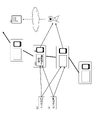
- FIG. 1 will be used to outline the communication system 1 having the relay device 100 of the present embodiment.
- the communication system 1 includes a relay device 100a, a relay device 100b, a sensor device 10, a gateway device (hereinafter, GW) 11, a communication terminal device 12a, a communication terminal device 12b, and a server device 13.
- GW gateway device
- the configuration of each device will be described later. Further, when referring to the whole relay device including the relay device 100a and the relay device 100b, it is described as the relay device 100, and when referring to the whole communication terminal device including the communication terminal device 12a and the communication terminal device 12b, it is described as the communication terminal device 12.
- the wireless communication method A is a long-range wireless communication method having a longer communication range than the wireless communication method B described later.
- 3G, 4G, and 5G for example, long-distance communication with low power consumption.
- Communication is performed by a low power consumption long-distance wireless communication method (LPWA (Low Power Wide Area)) that enables communication.
- LPWA Low Power Wide Area
- the LPWA method is a communication method that mainly uses the 800/900 MHz band called the sub giga band.
- eMTC enhanced Machine Type Communication
- 3GPP Third Generation Partnership Project
- NB-IoT NearBandInternet of Things
- SIGFOX registered trademark
- LoRa registered trademark
- PARCA® which is characterized by broadcast-type two-way communication proposed by the applicant of the present application, can also be used.
- the wireless communication method A is referred to as a long-distance wireless communication method.
- the relay device 100 further communicates with the communication terminal device 12 using the wireless communication method B (corresponding to the "second wireless communication method").
- the wireless communication method B is a communication method having a shorter communicable distance than the wireless communication method A, and is generally called a short-range wireless communication method.
- Examples of wireless communication method BB include Wi-Fi (registered trademark), ZigBee (registered trademark), Bluetooth (registered trademark), Bluetooth Low Energy (BLE), Felica (registered trademark), NFC (Near Field Communication), RFID, etc. Can be mentioned.
- BLE is used.
- the wireless communication method B is referred to as a short-range wireless communication method.
- Wi-Fi may be selected as the wireless communication method A
- BLE may be selected as the wireless communication method B.
- the GW 11 transmits the data received from the relay device 100 to the server device 13 via the Internet network.
- the user accesses the server device 13 using a general-purpose communication device such as a personal computer (PC), a smartphone, or a mobile phone, and the data is collected in the server device 13. Can be used.
- PC personal computer
- smartphone a smartphone
- mobile phone a mobile phone
- the sensor device 10 and the relay device 100 are described as different devices.
- the sensor device 10 and the relay device 100 may be devices having the same configuration. That is, the sensor device 10 may have a function as a relay device 100 described later, and the relay device 100 may have a function as a sensor device 10 described later.
- FIG. 1 shows a communication system in which two relay devices 100, that is, a relay device 100a and a relay device 100b, are arranged between the sensor device 10 and the GW 11.
- the number of relay devices 100 of the communication system 1 of the present embodiment can be any number.
- the data transmission method of the sensor device 10 and the relay device 100 employs a broadcast method in which a destination is not specified.
- a broadcast method in which a destination is not specified.
- a unicast method or a multicast method that specifies the destination may be adopted.
- the sensor device 10 has a sensor function of measuring and acquiring data indicating the surrounding environment of the place where the sensor device 10 is arranged. It is a device having a communication function of transmitting the acquired data by using a long-range wireless communication method.
- the sensor device 10 acquires data indicating the surrounding environment at preset time intervals (for example, 1 hour, 30 minutes, etc.), and uses a long-distance wireless communication method to provide data including data indicating the surrounding environment. Is transmitted to the relay device 100.
- the data indicating the surrounding environment acquired by the sensor device 10 will be referred to as sensor data, and the first data including the sensor data transmitted by the sensor device 10 to the relay device 100 and the data accompanying the sensor data. Further, the data transmitted by the sensor device 10 is used as the collected data.
- FIG. 2 shows an example of a data format of collected data, which is the first data transmitted by the sensor device 10 to the relay device 100.
- the first data includes the data length (Length), the sensor device identification ID (SensorID) that identifies the sensor device 10 itself, the sensor data (SensorData) acquired by the sensor device 10, and the sensor device 10.
- the position information of the sensor device 10 may be included.
- Temperature data is data indicating the temperature detected by the temperature sensor
- humidity data is data indicating the humidity detected by the humidity sensor
- vibration data is data indicating the amplitude and frequency of vibration detected by the vibration detection sensor
- illuminance data is optical sensor. It is the data which shows the intensity of the light detected by.
- the vibration data may be the output of the vibration power generation element
- the illuminance data may be the output of the photovoltaic power generation element.
- the vibration data and the illuminance data may be output as they are at the time of measurement, or may be cumulative values up to the time of measurement.
- the sensor data shown in FIG. 2 is an example and is not limited thereto.
- it may be position information indicating the position of the sensor device 10.
- it may be image information or audio information.
- the sensor data transmitted by the sensor device 10 to the relay device 100 may be plural or singular.
- the sensor device 10 can be installed in various places regardless of whether it is indoors or outdoors in order to acquire sensor data.
- the sensor device 10 can be installed in agricultural land, pasture, livestock barn, or the like.
- the sensor device 10 when installed in a paddy field, it is possible to detect the water level and sunshine duration of the paddy field in addition to the ambient temperature and humidity.
- the sensor device 10 When installed in pastures or barns, it can detect the movement of livestock as well as temperature and humidity.
- the sensor device 10 may be installed directly on the livestock. As a result, the farmer or the livestock farmer who is the user can remotely monitor the situation of the livestock by using these sensor data collected in the server device 13.
- the sensor device 10 can be installed in a river, a pond, or a dam.
- the water level and flow velocity can be detected.
- the local government which is the main body of river management, can remotely monitor the state of the river by using these sensor data collected in the server device 13.
- these sensor data can be used to predict disasters such as floods.
- the sensor device 10 is described as one device having both a sensor function and a communication function, but a physically separate sensor and a communication device are combined as the sensor device 10 of the present embodiment. May be good.
- the sensor and the communication device may be connected by wire or wirelessly.
- the sensor device 10 may be an electronic device equipped with various sensors such as a smartphone, a mobile phone, a tablet, a smart watch, a smart band, and a drone, in addition to a dedicated device.
- the configuration of the relay device 100 (100a, 100b) of the present embodiment will be described with reference to FIG.
- the relay device 100 includes a reception unit 101, a data generation unit 102, an addition unit 103, a first transmission unit 104, and a second transmission unit 105.
- the data generation unit 102 includes an identification ID generation unit 106, a communication quality acquisition unit 107, and an increment unit 108.
- the relay device 100a and the relay device 100b shown in FIG. 1 are devices having the same configuration as shown in FIG. However, since the data received by the receiving unit 101 and the data generated by the data generating unit 102 are slightly different between the relay device 100a and the relay device 100b, the relay device 100a and the relay device 100b will be described below.
- the relay device 100a is a relay device that relays data from the sensor device 10 to the relay device 100b described later.
- the receiving unit 101 of the relay device 100a receives the collected data consisting of the first data transmitted from the sensor device 10 (corresponding to the "first communication device") using the long-distance wireless communication method.
- the data generating unit 102 When the receiving unit 101 receives the collected data consisting of the first data, the data generating unit 102 generates the second data and outputs the second data to the adding unit 103.
- the data generation unit 102 not only generates the second data by newly generating new data, but also updates the contents of the first data included in the collected data received by the reception unit 101. By doing so, the second data may be generated.
- the data generation unit 102 generates the second data by performing the three determinations and processes described below.
- the identification ID generation unit 106 of the data generation unit 102 determines whether or not the received collected data includes the relay device identification ID (Receiver ID). In the present embodiment, the relay device identification ID is not recorded in the received collected data, so the identification ID generation unit 106 generates the relay device identification ID for identifying the relay device 100a.
- the relay device identification ID is not recorded in the received collected data, so the identification ID generation unit 106 generates the relay device identification ID for identifying the relay device 100a.
- the communication quality acquisition unit 107 of the data generation unit 102 determines whether or not the collected data transmitted from the sensor device 10 has been received.
- the communication quality acquisition unit 107 acquires the communication quality data by measuring the quality of the received signal of the collected data.
- the communication quality data may be acquired by measuring with the communication quality acquisition unit 107, or may be acquired by measuring with the receiving unit 101.
- Communication quality data is acquired, for example, by measuring RSSI (Received Signal Strength Indicator).
- the communication quality acquisition unit 107 replaces RSSI with RSRP (Reference Signal Received Power), RSRQ (Reference Signal Received Quality), SNR (signal to Noise Ratio), SIR (Signal to Interference power Ratio), and BER (Bit Error Rate). ), Or the average bit rate (bps) per unit time may be obtained.
- RSRP Reference Signal Received Power
- RSRQ Reference Signal Received Quality
- SNR signal to Noise Ratio
- SIR Signal to Interference power Ratio
- BER Bit Rate
- the increment unit 108 of the data generation unit 102 generates relay count data indicating the number of relays of the first data included in the collected data received by the reception unit 101.
- the increment unit 108 since the receiving unit 101 of the relay device 100a receives the collected data directly from the sensor device 10, the relay number data is not recorded in the first data. Therefore, the increment unit 108 generates relay count data indicating the relay count [1].
- the addition unit 103 includes the relay device identification ID generated by the identification ID generation unit 106, the communication quality data acquired by the communication quality acquisition unit 107, and the increment unit in the first data included in the collected data received by the reception unit 101.
- the second data consisting of the relay count data generated in 108 is added and output.
- FIG. 4 is an example of a data format of transfer data including first data and second data output from the addition unit 103 and transmitted from the first transmission unit 104 and the second transmission unit 105.
- the relay device identification ID (Receiver ID)
- the communication quality data (RSSI)
- the relay count data (Hopping Counter)
- the relay device identification ID (Receiver ID) is an ID that identifies the relay device that first received the collected data from the sensor device 10. In the present embodiment, since the relay device 100a first receives the collected data from the sensor device 10, the relay device identification ID of the relay device 100a is recorded.
- the communication quality data indicates the quality of the received signal of the collected data transmitted from the sensor device 10.
- RSSI which is communication quality data generated by the communication quality acquisition unit 107, is recorded.
- the relay count data indicates the number of times the relay device relayed the first data.
- the relay number [1] is recorded as the relay number data.
- the first transmission unit 104 uses the long-distance wireless communication method to transfer the transfer data composed of the first data and the second data output from the addition unit 103 to the relay device 100b (“second communication device”). Correspondence) to send.
- the second transmission unit 105 uses a short-range wireless communication method "simultaneously” or “continuously” when the first transmission unit 104 transmits the transfer data consisting of the first data and the second data.
- the transfer data including the first data and the second data output from the addition unit 103 is transmitted to the communication terminal device 12a (corresponding to the "third communication device").
- “simultaneous” means that it is sufficient that the transmission processing is performed at the same timing, and the time when the data is actually transmitted does not necessarily have to be the same timing.
- Continuous means that the data transmission processing may be continuously performed, and the transmission order is arbitrary.
- the relay device 100b is a relay device that relays the data received from the relay device 100a.
- the relay device 100b transmits data to the GW 11, but data may be transmitted to another relay device (not shown). Since the configuration of the relay device 100b is the same as the configuration of the relay device 100a, it will be described with reference to FIG.
- the receiving unit 101 of the relay device 100b receives the transfer data consisting of the first data and the second data transmitted from the relay device 100a (corresponding to the "first communication device") using the long-distance wireless communication method. do.
- the data generation unit 102 When the receiving unit 101 receives the transfer data consisting of the first data and the second data, the data generation unit 102 generates new second data as needed and adds the generated second data. Output to unit 103. In the present embodiment, the data generation unit 102 generates the second data by performing the three determinations and processes described below.
- the identification ID generation unit 106 of the data generation unit 102 determines whether or not the received transfer data includes the relay device identification ID. In the present embodiment, since the relay device identification ID of the relay device 100a is already recorded in the second data included in the transfer data, the identification ID generation unit 106 does not newly generate the relay device identification ID of the relay device 100b. ..
- the communication quality acquisition unit 107 of the data generation unit 102 determines whether or not the collected data transmitted from the sensor device 10 has been received.
- the reception unit 101 receives the transfer data, not the collected data transmitted from the sensor device 10, so that no new communication quality data is generated.
- the determination of whether or not the data is the collected data transmitted from the sensor device 10 may be determined by, for example, whether or not the data corresponding to the second data is included.
- the increment unit 108 of the data generation unit 102 generates relay count data indicating the number of relays of the first data included in the transfer data received by the reception unit 101.
- the increment unit 108 increments this and generates the relay count data indicating the relay count [2]. do.
- the addition unit 103 adds the second data generated by the data generation unit 102 to the transfer data received by the reception unit 101 and outputs the data. Specifically, the second data included in the transfer data received by the reception unit 101 is updated by overwriting the relay count data generated by the increment unit 108.
- the first transmission unit 104 uses a long-distance wireless communication method to transfer transfer data composed of the first data and the second data output from the addition unit 103 to the GW 11 or another relay device (“second). Corresponds to "communication device").
- the second transmission unit 105 uses a short-range wireless communication method "simultaneously” or “continuously” when the first transmission unit 104 transmits the transfer data consisting of the first data and the second data.
- the transfer data including the first data and the second data output from the addition unit 103 is transmitted to the communication terminal device 12b (corresponding to the "third communication device").
- the data transmitted by the first transmission unit 104 of the relay device 100 and the data transmitted by the second transmission unit 105 are the same, but the second one.
- the data transmitted by the transmission unit 105 may be a part of the data transmitted by the first transmission unit.
- the part may be a part of the types of data included in the first data and the second data, or may be a part of the data included in the first data and the second data. All types are transmitted, but by thinning out the number of data, it may be a part of the number of data contained in the first data and the second data.
- the part of the data corresponds to the "first data" and the "second data" of the present invention.
- the relay device 100 may be configured to provide a switch in the front stage or the rear stage of the second transmission unit 105, and the second transmission unit 105 transmits the transfer data only when the switch is ON. With such a configuration, the relay device 100 transmits relay data only from the first transmission unit 104 during normal operation, and transfers data from the second transmission unit 105 only when the relay device 100 is installed. Can be sent.
- the transfer data transmitted by the first transmission unit 104 and the transfer data transmitted by the second transmission unit 105 can be transmitted a plurality of times, respectively.
- the purpose of the first transmission unit 104 to transmit the transfer data using the long-distance wireless communication method is to upload the transfer data to the server device 13 via the GW 11, so that the number of transmissions of the transfer data is smaller. good.
- the reason why the second transmission unit 105 transmits the transfer data using the short-range wireless communication method is to search for an appropriate place where the relay device 100 is installed by using the communication terminal device 12. Therefore, it is better that the number of times the transferred data is transmitted is larger.
- the number of times the transfer data of the second transmission unit 105 is transmitted is larger than the number of times of transmission of the transfer data of the first transmission unit 104.
- the number of times the transfer data of the second transmission unit 105 is transmitted can be 30 to 50 times, and the number of times of transmission of the transfer data of the first transmission unit 104 can be 1 to 3 times.
- the transmission period of the transfer data of the second transmission unit 105 is longer than the transmission period of the transfer data of the first transmission unit 104.
- the transmission period of the transfer data of the second transmission unit 105 can be 3 minutes, and the transmission period of the transfer data of the first transmission unit 104 can be 30 seconds.
- the transmission cycle of the transfer data of the second transmission unit 105 is shorter than the transmission cycle of the transfer data of the first transmission unit 104.
- the transmission cycle of the transfer data of the second transmission unit 105 may be an interval of 1 second, and the transmission cycle of the transfer data of the first transmission unit 104 may be an interval of 5 seconds.
- the communication terminal device 12 (12a, 12b) is a device carried and operated by the installer when the relay device 100 is installed.
- a general-purpose communication device such as a smartphone, a mobile phone, a tablet terminal, or a personal computer (PC) as the communication terminal device 12 will be described.
- FIG. 5 shows the configuration of the communication terminal device 12.
- the communication terminal device 12 includes a receiving unit 121, a counter 122, and an output unit 123.
- the receiving unit 121 receives the transfer data transmitted from the relay device 100 (100a, 100b) using the short-range wireless communication method.
- the counter 122 counts the number of receptions, which is the number of times the relay data is received by the reception unit 121. In the present embodiment, the counter 122 counts the number of receptions for each sensor device identification ID of the sensor device 10 included in the second data of the relay data. In addition, the number of receptions may be counted for each relay device identification ID.
- the output unit 123 outputs all or part of the contents of the first data and the second data included in the relay data received by the reception unit 121 as an image or audio.
- the output unit 123 may further output the number of receptions counted by the counter 122.
- the above configuration can be realized by installing an application on the communication terminal device 12. For example, when the relay device 100 is newly installed or when it is desired to check the communication status of the relay device 100 whose installation has already been completed, the installer executes the application installed in the communication terminal device 12. When the application is executed, the communication terminal device 12 starts communication with the relay device 100 using the short-range wireless communication method, and the content of the required data among the first data and the second data, and the number of receptions. Is output as an image or audio.
- FIG. 6 shows an example of an image output from the output unit 123 of the communication terminal device 12.
- the sensor device ID, the relay device ID, the number of receptions, and the communication quality are displayed.
- the sensor device ID displays the contents of the sensor device identification ID (Sensor ID) shown in FIGS. 2 and 4.
- the relay device ID displays the contents of the relay device identification ID (Receiver ID) shown in FIG.
- the reception count indicates the reception count of the transfer data counted by the counter 122 for each sensor device ID.
- the communication quality indicates the content of the communication quality data (RSSI) shown in FIG.
- the reset function is a function that erases the contents of the transferred data processed so far by performing a reset, and targets the transferred data received after the reset as an output target of the output unit 123. For example, it can be used when the relay device is moved to start a new measurement.
- the scan start / end function is a function to start / end the measurement without resetting the data. Since the data is not reset, the end of the scan corresponds to the pause, and the start of the scan corresponds to the restart after the pause.
- the installer determines whether or not the installation position of the relay device 100 is appropriate based on the information output from the output unit 123 of the communication terminal device 12. can do. Specifically, the installer searches for an appropriate place as the installation place of the relay device while holding and moving the relay device 100 and checking the information on the screen of the smartphone.
- the installer can grasp the operating status of the already installed sensor device 10 and relay device 100 by using the communication terminal device 12. For example, if a building or equipment that affects the radio wave environment is installed after the sensor device 10 or the relay device 100 is installed, data may not be collected in the server device 13 due to changes in the radio wave environment. Therefore, by confirming the contents of the first data and the second data transmitted from the sensor device 10 and the relay device 100 that have already been installed, the sensor device 10 and the relay device 100 are appropriately used. Can be relocated to any location.
- the sensor device 10 that can collect the collected data or the sensor device 10 that can transfer the collected data can be specified.
- the relay device 100a can be installed in a place where the collected data can be received from all or many of the installed sensor devices 10. .
- the communication terminal device 12b outputs the transfer data of the relay device 100b as information, it is possible to confirm whether or not the collected data is directly received from the sensor device 10 without going through the relay device 100a.
- the collection route of the collected data can be narrowed down to the route from the relay device 100a, so that the relay device 100 can be narrowed down.
- the number of installations can be reduced.
- the relay device 100 that first transfers the collected data of the sensor device 10 as the transfer data can be specified.
- the communication terminal device 12b outputs the transfer data of the relay device 100b as information, it is possible to confirm whether or not the collection network of the collected data has been established from the combination of the relay device ID and the sensor device ID.
- the relay device 100 According to the number of receptions, it can be confirmed whether the relay device 100 is continuously transferring. That is, it can be confirmed that the sensor device 10 and the relay device 100 are continuously transferring the collected data and the transferred data by increasing the number of receptions.
- the communication quality it is possible to confirm the reception environment of the collected data transmitted from the sensor device 10. That is, since it is possible to confirm whether the relay device 100a is provided at a position where the collected data can be reliably received from the sensor device 10, the relay device 100a can be provided at a position where the communication quality is good. Further, if the communication quality is not improved, it can be determined whether or not it is necessary to further add the repeater 100.
- the content output from the output unit 123 of the communication terminal device 12 is not limited to the example shown in FIG.
- the output unit 123 may output relay count data (Hopping Counter) and transmission count data (Send Counter) as images in addition to the information shown in FIG.
- the content output from the output unit 123 of the communication terminal device 12 is not limited to displaying the information included in the transfer data as it is.
- the information contained in the transferred data may be displayed by processing or associating with other information.
- FIG. 7 shows an example of an image output from the output unit 123 of the communication terminal device 12.
- FIG. 7A is an example of displaying the reception status of the radio wave from the sensor device 10 and the other relay device 100 on the map in association with the position information.
- the position information is acquired by using a GPS or a gyro mounted on the communication terminal device 12.
- the position where it is appropriate to provide the relay device 100 is displayed by separately displaying the position where the reception condition is good for a predetermined value or more and the position where the reception condition is not good.
- FIG. 7 (b) the information obtained by the method of FIG. 7 (a) is subjected to statistical processing, and the area where the radio wave reception condition is good is displayed step by step.
- the GW 11 transmits the transfer data transmitted from the relay device 100 to the server device 13 via the Internet.
- a user can acquire and use data by accessing the server device 13 using a general-purpose personal computer or a mobile terminal device.
- the GW 11 may be configured to transmit the data transmitted from the server device 13 to the relay device 100 and the communication terminal device 12 by a long-distance wireless communication method or a short-range wireless communication method.
- the GW 11 may have the same configuration as the relay device 100 of the present embodiment, or at least include a first transmission unit 104 and a second transmission unit 105.
- the sensor device 10 acquires sensor data such as temperature data and humidity data (S101).
- the sensor device 10 uses the long-distance wireless communication method to transmit the first data including the sensor data acquired in S101 to the relay device 100a as collected data (S102).
- the data generation unit 102 When the relay device 100a receives the collected data from the sensor device 10, the data generation unit 102 generates the second data (S103). Then, using the long-distance wireless communication method, the first data included in the received collected data and the second data generated in S103 are transmitted to the relay device 100b as transfer data (S104). At the same time or continuously, using the short-range wireless communication method, the first data included in the received collected data and the second data generated in S103 are transmitted to the communication terminal device 12a as transfer data (S105). ).
- the communication terminal device 12a When the communication terminal device 12a receives the transfer data including the first data and the second data from the relay device 100a, the communication terminal device 12a counts the number of times the transfer data is received (S106). Then, the first data and the second data included in the received transfer data, and the number of times the transfer data is received are output as images or sounds (S107).
- the relay device 100b When the relay device 100b receives the transfer data including the first data and the second data from the relay device 100a, the relay device 100b newly generates the second data (S108). Then, using the long-distance wireless communication method, the received first data and the second data generated in S108 are transmitted to the GW 11 as transfer data (S109). At the same time or continuously, using the short-range wireless communication method, the received first data and the second data generated in S108 are transmitted to the communication terminal device 12b as transfer data (S110).
- the communication terminal device 12b Similar to the communication terminal device 12a, when the communication terminal device 12b receives the transfer data including the first data and the second data from the relay device 100b, the communication terminal device 12b counts the number of times the transfer data is received (S111). Then, the first data and the second data included in the received transfer data, and the number of times the tense data is received are output as an image or voice (S112).
- the GW 11 when the GW 11 receives the transfer data consisting of the first data and the second data from the relay device 100b, the GW 11 uploads the transfer data to the server device 13 (S113).
- relay devices 100 (100a, 100b) are arranged between the sensor device 10 and the GW 11 , but the number of relay devices 100 can be arbitrary. ..
- the sensor device 10 also transmits the collected data using the short-range wireless communication method in addition to transmitting the collected data consisting of the first data using the long-distance wireless communication method. It may be configured to do so.
- the installer can use the communication terminal device 12 to position the sensor device 10 at an appropriate position. It becomes possible to arrange.
- the relay device 100 transmits data received from the sensor device 10 and the communication device which is the relay device 100 by using two communication methods having different communicable distances.
- the data transmitted using the communication method having the shortest communicable distance is transmitted to the communication terminal device and notified to the installer. This allows the installer to determine whether the installation position of the relay device is an appropriate position for relaying data.
- the identification ID generation unit 106 determines whether or not the received collected data includes the relay device identification ID (Receiver ID), and if the relay device identification ID is not recorded, the relay device identification ID is identified. It was decided not to generate the relay device identification ID when the ID was generated and the relay device identification ID was recorded. By performing such an operation, the relay device identification ID included in the second data of the transfer data indicates the relay device 100a that first received the collected data from the sensor device 10. This information has significance as position information, that is, the sensor device 10 and the relay device 100a are communicating with each other, and the position of the sensor device 10 exists within a certain range with respect to the relay device 100a. There is also.
- the identification ID generation unit 106 may generate the relay device identification ID regardless of the content of the received collected data. By performing such an operation, the relay device identification ID indicates the relay device 100 that has recently transferred. Since this information means from which relay device 100 the received transfer data is transmitted, it is possible to confirm a rough communication path of the transfer data.
- the identification ID generation unit 106 generates the relay device identification ID regardless of the content of the received collected data, and the addition unit 103 adds the generated relay device identification ID without overwriting. You may. By performing such an operation, the relay device identification ID indicates a communication path starting from the sensor device 10.
- the communication quality acquisition unit 107 determines whether or not the collected data transmitted from the sensor device 10 has been received, and acquires the communication quality data when the collected data is received. ..
- the communication quality acquisition unit 107 may acquire the communication quality data of the received collected data or the transferred data regardless of whether the received data is the collected data or the transferred data. By performing such an operation, the communication quality data indicates the reception environment of the relay device. Using this information, the relay device 100 can be installed at a position where the communication quality data indicates a good reception environment.
- the position information data generation unit 102 may generate position information indicating the position of the relay device 100 and include it in the second data. At this time, it may be overwritten or added in association with the relay device identification ID of (1) above.
- the communication terminal device 20 has the same configuration as the communication terminal device 12, and receives transfer data transmitted from the pseudo relay device 200 using a short-range wireless communication method.
- the communication terminal device 20 further has a wireless communication unit for long-distance wireless communication and a position information acquisition unit. Examples of long-distance wireless communication include wideband cellular communication called 3G, 4G, and 5G, but other methods can also be used. Further, a communication method corresponding to a longer distance such as a satellite phone can be used.
- the pseudo relay device 200 and the communication terminal device 20 are mounted on a mobile body.
- Examples of moving objects include people, automobiles, motorcycles, ships, drones, helicopters, and aircraft.
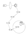
- the collected data of the sensor device 10 installed in the forest it will be described as being mounted on the drone.
- the drone equipped with the pseudo relay device 200 and the communication terminal device 20 flies over the forest. Then, when the pseudo relay device 200 mounted on the drone receives the collected data transmitted from the sensor device 10, the pseudo relay device 200 transmits the transfer data from the first transmission unit 104 and the second transmission unit 105.
- the communication terminal device 20 mounted on the drone receives the transfer data. Then, the transfer data is transmitted by long-distance wireless communication together with the position information acquired by the position information acquisition unit at the position where the transfer data is received.
- the transmitted location information and transfer data are stored in the server device 13 via the base station and the cloud. If the communication terminal device 20 cannot communicate with the base station, it may be stored in a storage unit provided in the communication terminal device 20 and transmitted when it becomes possible to communicate with the base station. Alternatively, after collecting the drone, the location information and the transfer data stored in the storage unit of the communication terminal device 20 may be taken out.
- the transfer data transmitted from the first transmission unit 104 of the pseudo relay device 200 can be simultaneously received by another relay device 100 already installed or another mobile body having the pseudo relay device 200. That is, it can be used to confirm whether or not relay is possible.
- the data of the sensor device 10 is received by the pseudo relay device 200 provided in the drone, the transfer data is transmitted from the first transmission unit 104, and another pseudo relay device provided in the vehicle located away from the drone is transmitted. It may be confirmed whether the relay device 200 can receive the transfer data from the flight position of the drone.
- the installation location of 100 can be optimized. For example, when the pseudo relay device 200 is mounted on a moving body that can operate autonomously and is not physically restricted, such as a drone, it takes time for a person to go to the planned installation location of the relay device 100. Even so, the time required to determine the installation location of the relay device 100 can be shortened. In addition, it is possible to automate the determination of the installation location of the relay device 100. When deciding the installation location of the relay device 100, the sensor device 10 is not always necessary. Similar to the pseudo repeater 200, the sensor device 10 may be simulated at the planned installation location. The sensor device 10 may also be mounted on another drone.
- the location information and transmission data stored in the server device 13 can be output by, for example, the method shown in FIG. Then, the relay device 100 is provided at a place suitable for installing the relay device 100.
- a pseudo relay device 200 By using such a pseudo relay device 200 together with a moving body, it is possible to perform a preliminary search in a place where a person cannot easily enter, such as a mountain or the sea. Further, by mounting the pseudo relay device 200 and the communication terminal device 20 on the automobile and searching while moving on the road, it is possible to efficiently search for a place suitable for installing the relay device 100. For example, a place where the collected data transmitted from the sensor device 10 installed in the gas manhole can be received can be searched by the pseudo relay device 200 and the communication terminal device 20 mounted on the automobile.
- a pseudo relay device 200 together with a moving body, it is possible to search for a missing person in a mountain or the sea. For example, if the missing person possesses a terminal device corresponding to the sensor device 10, the search can be performed by flying the drone equipped with the pseudo relay device 200 around the missing place.
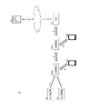
- FIG. 10 is a diagram illustrating a method of installing the relay device 100. This method assumes that the relay device 100 is installed, for example, in order to watch over the workers working in the forest.
- the GW 11 is connected to the server device 13 and also has a function of transmitting dummy data.
- the worker possesses a plurality of relay devices 100 and also possesses a communication terminal device 12.
- a smart band to be worn on the arm is worn as the sensor device 10. Then, while advancing to the depths of the forest, the output of the communication terminal device 12 is confirmed, and the relay device 100a is installed at a position where the dummy data transmitted from the GW 11 can be received.
- the worker confirms the output of the communication terminal device 12 while further advancing to the depths of the forest, and installs the relay device 100b at a position where the dummy data transferred from the relay device 100a installed earlier can be received. In this way, the relay device 100b is sequentially installed until the target work area is reached.
- the smart band is equipped with sensors such as a thermometer, a pulse rate monitor, and an accelerometer.
- the sensor data is transmitted to the server device 13 via the relay device 100 and the GW 11.
- the relay device 100 By providing the relay device 100 on the route leading to the work area in this way, it is possible to watch over the worker even in a place where the radio wave of the mobile phone is difficult to reach. For example, by monitoring the sensor data, it is possible to detect that the body temperature or pulse is abnormal. Alternatively, the movement of the worker can be detected by the position information transmitted from the GPS. Further, the acceleration information transmitted from the acceleration sensor can detect an abnormality such as a fall or a fall of the operator. Further, in addition to the sensor data, the operator may be able to transmit an SOS signal complaining of his / her malfunction.
- a communication terminal device 12 such as a smartphone may be used instead of the smart band.
- the installation interval of the relay device 100 may be an interval in which the radio wave of the long-distance wireless communication system can be received, or an interval in which the radio wave of the short-range wireless communication system can be received.
- the relay device 100 of the present embodiment includes two transmission units, a first transmission unit 104 and a second transmission unit 105, and the reception unit receives data transmitted by a long-distance wireless communication method. It had only part 101.
- the relay device 200 of the present embodiment in addition to the first receiving unit 101 that receives the data transmitted by the long-distance wireless communication method, the relay device 200 receives the data transmitted by the short-range wireless communication method.
- a unit 109 is provided.
- FIG. 11 shows the configuration of the relay device 200.
- the configuration common to the relay device 100 of FIG. 3 uses the same drawing number as the relay device 100 of FIG. 3, and the description of FIG. 3 is quoted.
- the second receiving unit 109 receives data transmitted from the communication terminal device 12 (corresponding to the "fourth communication device") using the short-range wireless communication method (corresponding to the "second communication method”). ..
- the data received by the second receiving unit 109 is transmitted from the first transmitting unit 104 and the second transmitting unit 105 using their respective communication methods.
- the relay device 200 can perform uplink / downlink bidirectional communication with the communication terminal device 12.
- the data transmitted from the communication terminal device 12a can be received by the communication terminal device 12b via the relay device 200a and the relay device 200b.
- the data transmitted from the communication terminal device 12b can be received by the communication terminal device 12a via the relay device 200b and the relay device 200a.
- Such a communication system 2 can also be used for watching over an operator, as in the application example of the first embodiment.
- the smart band 10 and the communication terminal device 12a held by the operator correspond to the short-range wireless communication method.
- the smart band 10 or the communication terminal device 12a is provided with sensors such as a thermometer, a pulse rate monitor, and an acceleration sensor. Further, the smart band 10 or the communication terminal device 12a can transmit an SOS signal in which the worker complains about his / her malfunction.
- the SOS signal is transferred to the server device 13 via the relay device 200 and the GW 11, and the notification is transmitted from the server device 13.
- the transfer is also performed to the communication terminal device 12b held by the other worker. As a result, other workers can quickly rush to the rescue of the worker.
- the SOS signal was focused on as an example of the data to be transmitted, but by using the position information transmitted from the GPS provided in the smart band 10 or the communication terminal device 12a and the acceleration information transmitted from the acceleration sensor. , You can watch the situation of the worker.
- the data transmitted by the first transmission unit 104 of the relay device 200 and the data transmitted by the second transmission unit 105 can be transmitted a plurality of times, respectively.
- the purpose of transmitting data by the first transmission unit 104 using the long-distance wireless communication method is to upload the data to the server device 13 via the GW 11, the number of transmissions of the transferred data may be smaller. ..
- the purpose of transmitting data by the second transmission unit 105 using the short-range wireless communication method is to inform other workers in the area covered by the communication system 2 of the occurrence of an abnormality. Therefore, it is better that the number of times the transferred data is transmitted is larger.
- the number of times the data of the second transmission unit 105 is transmitted is larger than the number of times the data of the first transmission unit 104 is transmitted.
- the data transmission period of the second transmission unit 105 is longer than the data transmission period of the first transmission unit 104. Desirably, it is desirable to continue the transmission until there is a response from the communication terminal device 12b.
- the data transmission cycle of the second transmission unit 105 is shorter than the data transmission cycle of the first transmission unit 104.
- the block diagram used in the explanation of the embodiment is a classification and arrangement of the configuration of the device according to the function.
- the blocks showing each function are realized by any combination of hardware or software. Further, since the block diagram shows the function, the block diagram can be grasped as the disclosure of the invention of the method and the invention of the program that realizes the method.
- the communication system including the relay device of this embodiment can be used not only for agriculture and river management, but also for searching for unknown persons and monitoring and watching over agricultural workers.
Landscapes
- Engineering & Computer Science (AREA)
- Computer Networks & Wireless Communication (AREA)
- Signal Processing (AREA)
- Mobile Radio Communication Systems (AREA)
- Arrangements For Transmission Of Measured Signals (AREA)
- Telephonic Communication Services (AREA)
- Radio Relay Systems (AREA)
Priority Applications (5)
| Application Number | Priority Date | Filing Date | Title |
|---|---|---|---|
| JP2022559222A JP7833785B2 (ja) | 2020-10-29 | 2021-10-28 | 中継装置 |
| CN202180073718.1A CN116508342A (zh) | 2020-10-29 | 2021-10-28 | 中继装置 |
| US18/034,438 US12526037B2 (en) | 2020-10-29 | 2021-10-28 | Relay device |
| US19/363,376 US20260046142A1 (en) | 2020-12-21 | 2025-10-20 | Image processing apparatus and method |
| US19/413,995 US20260095239A1 (en) | 2020-10-29 | 2025-12-09 | Relay device |
Applications Claiming Priority (2)
| Application Number | Priority Date | Filing Date | Title |
|---|---|---|---|
| JP2020-181554 | 2020-10-29 | ||
| JP2020181554 | 2020-10-29 |
Related Child Applications (4)
| Application Number | Title | Priority Date | Filing Date |
|---|---|---|---|
| US18/034,438 A-371-Of-International US12526037B2 (en) | 2020-10-29 | 2021-10-28 | Relay device |
| US18/257,559 A-371-Of-International US12463825B2 (en) | 2020-12-21 | 2021-10-28 | Image processing apparatus and method |
| US19/363,376 Continuation US20260046142A1 (en) | 2020-12-21 | 2025-10-20 | Image processing apparatus and method |
| US19/413,995 Continuation US20260095239A1 (en) | 2020-10-29 | 2025-12-09 | Relay device |
Publications (1)
| Publication Number | Publication Date |
|---|---|
| WO2022092185A1 true WO2022092185A1 (ja) | 2022-05-05 |
Family
ID=81381516
Family Applications (1)
| Application Number | Title | Priority Date | Filing Date |
|---|---|---|---|
| PCT/JP2021/039775 Ceased WO2022092185A1 (ja) | 2020-10-29 | 2021-10-28 | 中継装置 |
Country Status (4)
| Country | Link |
|---|---|
| US (2) | US12526037B2 (https=) |
| JP (1) | JP7833785B2 (https=) |
| CN (1) | CN116508342A (https=) |
| WO (1) | WO2022092185A1 (https=) |
Cited By (2)
| Publication number | Priority date | Publication date | Assignee | Title |
|---|---|---|---|---|
| JP2024021986A (ja) * | 2022-08-05 | 2024-02-16 | Smk株式会社 | 通信制御装置、通信制御方法及びデータ収集システム |
| JP2024148073A (ja) * | 2023-04-04 | 2024-10-17 | 横河電機株式会社 | サイトサーベイ装置、サイトサーベイプログラム、及びサイトサーベイ方法 |
Citations (2)
| Publication number | Priority date | Publication date | Assignee | Title |
|---|---|---|---|---|
| JP2015171075A (ja) * | 2014-03-10 | 2015-09-28 | Necプラットフォームズ株式会社 | 無線通信端末、無線通信システムおよび無線通信方法 |
| JP2017108260A (ja) * | 2015-12-09 | 2017-06-15 | 日本電信電話株式会社 | 無線センサ中継装置およびセンシングシステム |
Family Cites Families (6)
| Publication number | Priority date | Publication date | Assignee | Title |
|---|---|---|---|---|
| JP5374743B2 (ja) * | 2010-12-15 | 2013-12-25 | 株式会社日立製作所 | 無線ネットワークシステム、及び、無線通信装置 |
| WO2017004701A1 (en) * | 2015-07-03 | 2017-01-12 | Technologies Retia Inc. | Device and architecture for low-power networked communication |
| JP6623137B2 (ja) | 2016-09-21 | 2019-12-18 | 株式会社東芝 | 通信装置、コンピュータプログラムおよび無線通信システム |
| JP6852515B2 (ja) * | 2017-03-31 | 2021-03-31 | 沖電気工業株式会社 | センサ管理システム、センサ管理方法、センサ管理プログラム及びセンサ管理装置 |
| US11284231B2 (en) * | 2017-10-31 | 2022-03-22 | Sumitomo Electric Industries, Ltd. | Wireless sensor system, management device, communication control method and communication control program |
| US20200359114A1 (en) * | 2019-05-09 | 2020-11-12 | Panasonic Intellectual Property Management Co., Ltd. | Wireless sensor system |
-
2021
- 2021-10-28 US US18/034,438 patent/US12526037B2/en active Active
- 2021-10-28 CN CN202180073718.1A patent/CN116508342A/zh active Pending
- 2021-10-28 WO PCT/JP2021/039775 patent/WO2022092185A1/ja not_active Ceased
- 2021-10-28 JP JP2022559222A patent/JP7833785B2/ja active Active
-
2025
- 2025-12-09 US US19/413,995 patent/US20260095239A1/en active Pending
Patent Citations (2)
| Publication number | Priority date | Publication date | Assignee | Title |
|---|---|---|---|---|
| JP2015171075A (ja) * | 2014-03-10 | 2015-09-28 | Necプラットフォームズ株式会社 | 無線通信端末、無線通信システムおよび無線通信方法 |
| JP2017108260A (ja) * | 2015-12-09 | 2017-06-15 | 日本電信電話株式会社 | 無線センサ中継装置およびセンシングシステム |
Cited By (4)
| Publication number | Priority date | Publication date | Assignee | Title |
|---|---|---|---|---|
| JP2024021986A (ja) * | 2022-08-05 | 2024-02-16 | Smk株式会社 | 通信制御装置、通信制御方法及びデータ収集システム |
| JP7670005B2 (ja) | 2022-08-05 | 2025-04-30 | Smk株式会社 | 通信制御装置、通信制御方法及びデータ収集システム |
| JP2024148073A (ja) * | 2023-04-04 | 2024-10-17 | 横河電機株式会社 | サイトサーベイ装置、サイトサーベイプログラム、及びサイトサーベイ方法 |
| JP7848737B2 (ja) | 2023-04-04 | 2026-04-21 | 横河電機株式会社 | サイトサーベイ装置、サイトサーベイプログラム、及びサイトサーベイ方法 |
Also Published As
| Publication number | Publication date |
|---|---|
| JP7833785B2 (ja) | 2026-03-23 |
| US20230388003A1 (en) | 2023-11-30 |
| JPWO2022092185A1 (https=) | 2022-05-05 |
| US20260095239A1 (en) | 2026-04-02 |
| CN116508342A (zh) | 2023-07-28 |
| US12526037B2 (en) | 2026-01-13 |
Similar Documents
| Publication | Publication Date | Title |
|---|---|---|
| US12172535B2 (en) | Unmanned aerial vehicle drive testing and mapping of carrier signals | |
| US9924702B2 (en) | Mobile telephone dog training tool and method | |
| US20260095239A1 (en) | Relay device | |
| US9538725B2 (en) | Mobile telephone dog training tool and method | |
| US9894536B2 (en) | Motion-controlled device for supporting planning, deployment or operation of a wireless network | |
| US9456361B1 (en) | System, method, and computer program for performing mobile network related tasks based on performance data acquired by an unmanned vehicle | |
| EP3577482B1 (en) | Method system and apparatus supporting a surveillance of positions of devices | |
| JP5164729B2 (ja) | 位置情報処理システム | |
| US20100019924A1 (en) | Position finding system for people, animals and objects | |
| CN104683945B (zh) | 一种移动终端的定位方法、设备和系统 | |
| Shi et al. | A survey on multi-unmanned aerial vehicle communications for autonomous inspections | |
| JP5045506B2 (ja) | 通信方法および無線通信システム | |
| KR101732870B1 (ko) | 드론을 이용한 네트워크 최적 위치 탐색 시스템 | |
| JP6322315B1 (ja) | 通信システム、通信方法、及びプログラム | |
| CN105611509A (zh) | 一种定位短信诈骗伪基站的方法 | |
| Hadiwardoyo et al. | Evaluating UAV-to-Car communications performance: Testbed experiments | |
| Karatzia et al. | Implementing mission-critical UAV swarm coordination through the integration of LoRa and ROS frameworks | |
| CN105357643A (zh) | 基于ZigBee和GPRS的双网监护系统 | |
| Nielsen et al. | Location-based mobile relay selection and impact of inaccurate path loss model parameters | |
| JP2020021310A (ja) | 移動体把握システム | |
| Poovalingam et al. | LoRA Communication Testing for LOS and NLOS Operations | |
| Chaudhary et al. | A survey on the implementation of wireless sensor network breadcrumb trails for sensing and localization | |
| US20250274998A1 (en) | Data-communication system and method of making data-communication | |
| KR100972514B1 (ko) | 고정 라우팅 알고리즘을 이용한 무선 호출 방법 및 장치 | |
| US20250294319A1 (en) | Rescue system and rescue device to facilitate rescue |
Legal Events
| Date | Code | Title | Description |
|---|---|---|---|
| 121 | Ep: the epo has been informed by wipo that ep was designated in this application |
Ref document number: 21886302 Country of ref document: EP Kind code of ref document: A1 |
|
| ENP | Entry into the national phase |
Ref document number: 2022559222 Country of ref document: JP Kind code of ref document: A |
|
| WWE | Wipo information: entry into national phase |
Ref document number: 202180073718.1 Country of ref document: CN |
|
| WWE | Wipo information: entry into national phase |
Ref document number: 18034438 Country of ref document: US |
|
| NENP | Non-entry into the national phase |
Ref country code: DE |
|
| 122 | Ep: pct application non-entry in european phase |
Ref document number: 21886302 Country of ref document: EP Kind code of ref document: A1 |
|
| WWG | Wipo information: grant in national office |
Ref document number: 18034438 Country of ref document: US |