WO2022091509A1 - レンズユニット - Google Patents
レンズユニット Download PDFInfo
- Publication number
- WO2022091509A1 WO2022091509A1 PCT/JP2021/028205 JP2021028205W WO2022091509A1 WO 2022091509 A1 WO2022091509 A1 WO 2022091509A1 JP 2021028205 W JP2021028205 W JP 2021028205W WO 2022091509 A1 WO2022091509 A1 WO 2022091509A1
- Authority
- WO
- WIPO (PCT)
- Prior art keywords
- lens
- storage groove
- adhesive
- lens unit
- discharge hole
- Prior art date
- Legal status (The legal status is an assumption and is not a legal conclusion. Google has not performed a legal analysis and makes no representation as to the accuracy of the status listed.)
- Ceased
Links
Images


Classifications
-
- G—PHYSICS
- G02—OPTICS
- G02B—OPTICAL ELEMENTS, SYSTEMS OR APPARATUS
- G02B7/00—Mountings, adjusting means, or light-tight connections, for optical elements
- G02B7/02—Mountings, adjusting means, or light-tight connections, for optical elements for lenses
- G02B7/021—Mountings, adjusting means, or light-tight connections, for optical elements for lenses for more than one lens
-
- G—PHYSICS
- G03—PHOTOGRAPHY; CINEMATOGRAPHY; ANALOGOUS TECHNIQUES USING WAVES OTHER THAN OPTICAL WAVES; ELECTROGRAPHY; HOLOGRAPHY
- G03B—APPARATUS OR ARRANGEMENTS FOR TAKING PHOTOGRAPHS OR FOR PROJECTING OR VIEWING THEM; APPARATUS OR ARRANGEMENTS EMPLOYING ANALOGOUS TECHNIQUES USING WAVES OTHER THAN OPTICAL WAVES; ACCESSORIES THEREFOR
- G03B17/00—Details of cameras or camera bodies; Accessories therefor
- G03B17/02—Bodies
- G03B17/08—Waterproof bodies or housings
-
- G—PHYSICS
- G02—OPTICS
- G02B—OPTICAL ELEMENTS, SYSTEMS OR APPARATUS
- G02B7/00—Mountings, adjusting means, or light-tight connections, for optical elements
- G02B7/02—Mountings, adjusting means, or light-tight connections, for optical elements for lenses
-
- G—PHYSICS
- G02—OPTICS
- G02B—OPTICAL ELEMENTS, SYSTEMS OR APPARATUS
- G02B7/00—Mountings, adjusting means, or light-tight connections, for optical elements
- G02B7/02—Mountings, adjusting means, or light-tight connections, for optical elements for lenses
- G02B7/025—Mountings, adjusting means, or light-tight connections, for optical elements for lenses using glue
-
- G—PHYSICS
- G03—PHOTOGRAPHY; CINEMATOGRAPHY; ANALOGOUS TECHNIQUES USING WAVES OTHER THAN OPTICAL WAVES; ELECTROGRAPHY; HOLOGRAPHY
- G03B—APPARATUS OR ARRANGEMENTS FOR TAKING PHOTOGRAPHS OR FOR PROJECTING OR VIEWING THEM; APPARATUS OR ARRANGEMENTS EMPLOYING ANALOGOUS TECHNIQUES USING WAVES OTHER THAN OPTICAL WAVES; ACCESSORIES THEREFOR
- G03B2217/00—Details of cameras or camera bodies; Accessories therefor
- G03B2217/002—Details of arrangement of components in or on camera body
Definitions
- This disclosure relates to a lens unit.
- the manufacturer when the lens is adhered to the lens barrel, the manufacturer applies the adhesive to the groove provided in the lens barrel.
- the manufacturer adheres the lens barrel to the lens by fitting the lens into the lens barrel so that the lens is placed on the groove coated with the adhesive.
- One aspect of the lens unit for solving the above problem includes a lens, a lens barrel, a storage groove, and a discharge hole.
- the lens barrel accommodates the lens.
- the storage groove stores an adhesive formed in the lens barrel for joining the lens and the lens barrel.
- the discharge hole is a hole formed in the storage groove for discharging air.
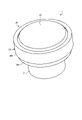
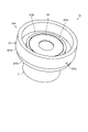
- FIG. 1 is a perspective view showing the appearance of the lens unit 1 according to one aspect of the first embodiment of the present disclosure.
- FIG. 2 is a perspective view showing the appearance of the lens unit 1 according to one aspect of the first embodiment of the present disclosure in a state where the first lens is removed.
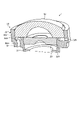
- FIG. 3 is a cross-sectional view showing a cross section of the lens unit 1 according to one aspect of the first embodiment of the present disclosure.
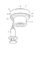
- FIG. 4 is a diagram showing a method of injecting an adhesive into the lens unit 1 according to one aspect of the first embodiment of the present disclosure.
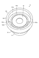
- FIG. 5 is a cross-sectional view showing a state in which the storage groove of the lens unit 1 according to one aspect of the first embodiment of the present disclosure is filled with an adhesive.
- FIG. 1 is a perspective view showing the appearance of the lens unit 1 according to one aspect of the first embodiment of the present disclosure.
- FIG. 2 is a perspective view showing the appearance of the lens unit 1 according to one aspect of the first embodiment of the present disclosure in a state where the
- FIG. 6 is a perspective view showing the appearance of the lens unit according to one embodiment of the first embodiment of the present disclosure in a state where the first lens is removed.
- FIG. 7 is a cross-sectional view showing a cross section of a lens unit according to one embodiment of the first embodiment of the present disclosure.
- FIG. 8 is a perspective view showing the appearance of the lens unit according to one aspect of the second embodiment of the present disclosure in a state where the first lens is removed.
- FIG. 9 is a cross-sectional view showing a cross section of the lens unit according to the second embodiment of the present disclosure.
- FIG. 10 is a diagram showing a method of injecting an adhesive into a lens unit according to one aspect of the second embodiment of the present disclosure.
- FIG. 11 is a perspective view showing a state in which the storage groove of the lens unit according to one aspect of the second embodiment of the present disclosure is filled with an adhesive.
- FIG. 1 is a perspective view showing the appearance of the lens unit 1 according to one aspect of the first embodiment of the present disclosure.
- FIG. 2 is a perspective view showing the appearance of the lens unit 1 according to one aspect of the first embodiment of the present disclosure in a state where the first lens 10 is removed.
- FIG. 3 is a cross-sectional view showing a cross section of the lens unit 1 according to one aspect of the first embodiment of the present disclosure.
- the lens unit 1 includes a lens barrel 30 to which the first lens 10 and the second lens 20 are mounted. That is, the lens barrel 30 accommodates the first lens 10 and the second lens 20.
- the lens barrel 30 has a body portion 31 and a flange portion 32 having a width wider than that of the body portion 31.
- the body portion 31 has a cylindrical shape.
- the body portion 31 is the tip of the upper portion, and the second lens 20 is fitted inside the flange portion 32.
- the body portion 31 shown in FIGS. 1 and 2 has a cylindrical shape. That is, the body portion 31 has a circular cross-sectional shape.
- the body portion 31 is not limited to a circular cross-sectional shape, but may have an elliptical shape, a triangular shape, a quadrangular shape, or any other shape. You may.
- the flange portion 32 is provided in the lens barrel 30 and is a portion for joining the first lens 10.
- the flange portion 32 is provided at the upper end of the body portion 31. Further, the flange portion 32 has a bottom portion 321 and a wall portion 322.
- the bottom portion 321 is the bottom of the flange portion 32.
- the wall portion 322 is a wall surrounding the bottom portion 321.
- the inner diameter of the wall portion 322 is substantially the same as that of the first lens 10. As a result, the first lens 10 is fitted into the flange portion 32.
- the bottom portion 321 has a storage groove 323 which is a groove in which the adhesive 3 is stored.
- the storage groove 323 is a groove formed in the lens barrel 30 for storing the adhesive 3 for joining the first lens 10 and the lens barrel 30. More specifically, the storage groove 323 is provided on the side of the abutting portion 324 to which the bottom surface of the first lens 10 is abutted on the flange portion 32, and has an annular shape having substantially the same size as the outer edge of the first lens 10. The groove is closed by the first lens 10.
- the surface of the abutting portion 324 shown in FIGS. 2 and 3 has a planar shape. Therefore, the opening of the storage groove 323 is closed by the first lens 10 when the first lens 10 is abutted against the flange portion 32. That is, as shown in FIG. 3, the storage groove 323 is closed by the first lens 10.
- the surface of the abutting portion 324 is not limited to a planar shape, but may have a convex shape with a sharp tip, or may have another shape.
- the flange portion 32 has an injection hole 325 and a discharge hole 326.
- the injection hole 325 is a hole formed in the storage groove 323 for injecting the adhesive 3. That is, the injection hole 325 is a hole for injecting the adhesive 3 for adhering the first lens 10 into the storage groove 323. Further, the injection hole 325 is formed on the bottom surface of the storage groove 323. More specifically, the injection hole 325 is a hole that penetrates the bottom portion 321 of the flange portion 32 and is a hole that is passed from the outside of the flange portion 32 to the storage groove 323.
- the injection hole 325 is not limited to the bottom surface of the storage groove 323, but may be formed on the side surface of the storage groove 323.
- the injection hole 325 shown in FIG. 3 is formed substantially parallel to the optical axis direction of the lens unit 1, but is not limited to being substantially parallel and may be provided at any angle.
- the discharge hole 326 is a hole formed in the storage groove 323 for discharging air.
- the discharge hole 326 discharges air from the storage groove 323 when the adhesive 3 for adhering the first lens 10 is filled in the storage groove 323.
- the discharge hole 326 is formed on the side surface of the storage groove 323. More specifically, the discharge hole 326 is a hole that penetrates the wall portion 322 of the flange portion 32 and is a hole that is passed from the outside of the flange portion 32 to the storage groove 323.
- the discharge hole 326 is provided on the storage groove 323 facing the injection hole 325 with the center of the storage groove 323 interposed therebetween.
- the discharge hole 326 does not have to be a hole that penetrates to the outside of the flange portion 32 as long as there is a space for retracting the air in the storage groove 323.
- the discharge hole 326 shown in FIG. 3 is formed substantially perpendicular to the optical axis direction of the lens unit 1, but is not limited to the substantially perpendicular direction and may be provided at any angle.
- the diameter of the injection hole 325 and the discharge hole 326 is 0.02 mm or more. That is, the cross-sectional area of the injection hole 325 and the discharge hole 326 is 0.0003 square millimeter or more.
- the size of the injection hole 325 and the discharge hole 326 is an example, and may be arbitrarily changed according to various conditions such as the viscosity of the adhesive 3.
- cross-sectional shape of the injection hole 325 and the discharge hole 326 shown in FIGS. 2 and 3 is circular.
- the cross-sectional shape of the injection hole 325 and the discharge hole 326 is not limited to a circle, but may be an ellipse, a triangle, a polygon, or any shape. May be.
- the flange portion 32 shown in FIGS. 2 and 3 is provided with one injection hole 325 and one discharge hole 326, respectively.
- the injection hole 325 and the discharge hole 326 are not limited to one, and a plurality of injection holes 326 may be provided. Further, the number of injection holes 325 and the number of discharge holes 326 do not have to match.
- the method of forming the injection hole 325 and the discharge hole 326 is not limited.
- the injection hole 325 and the discharge hole 326 may be formed by resin insert molding, secondary processing, or another method.
- FIG. 4 is a diagram showing a method of injecting the adhesive 3 into the lens unit 1 according to one aspect of the first embodiment of the present disclosure.
- FIG. 5 is a cross-sectional view showing a state in which the storage groove 323 of the lens unit 1 according to one aspect of the first embodiment of the present disclosure is filled with the adhesive 3.
- the syringe 2 is filled with an adhesive 3 for adhering the first lens 10. Then, the syringe 2 injects the adhesive 3 into the storage groove 323 when the needle is inserted into the injection hole 325 as shown in FIG. The adhesive 3 is replenished from the injection hole 325 toward the discharge hole 326 along the storage groove 323. At this time, the discharge hole 326 discharges the air in the storage groove 323 extruded by the adhesive 3 to the outside of the storage groove 323. As a result, the storage groove 323 is filled with the adhesive 3.
- the adhesive 3 is not limited to the syringe 2, and may be injected into the storage groove 323 by another instrument or device.
- the syringe 2 may continue to inject the adhesive 3 for a predetermined period even after the adhesive 3 is discharged from the discharge hole 326.
- the syringe 2 can discharge the air in the storage groove 323 to the outside. Therefore, the lens unit 1 can suppress the formation of cavities because the possibility that bubbles are generated is reduced.
- the syringe 2 may be injected with the adhesive 3 in a state where the lens unit 1 is tilted so that the discharge hole 326 is directed upward.
- the air in the storage groove 323 floats up and is discharged to the outside of the storage groove 323 through the discharge hole 326. Therefore, the lens unit 1 can suppress the formation of cavities because the possibility that bubbles are generated is reduced.
- the discharge hole 326 may be equipped with a suction device that sucks out the air in the storage groove 323.
- a suction device that sucks out the air in the storage groove 323.
- the lens unit 1 includes a lens barrel 30.
- the lens barrel 30 includes a flange portion 32 for joining the first lens 10.
- the flange portion 32 has an annular shape having substantially the same size as the outer edge of the first lens 10, and has a storage groove 323 in which the opening is closed by the first lens 10.
- the storage groove 323 has a discharge hole 326 for discharging air from the storage groove 323 when the adhesive 3 for adhering the first lens 10 is filled in the storage groove 323. Therefore, since the lens unit 1 can discharge the bubbles formed inside the adhesive interface and the adhesive layer, it is possible to suppress the formation of cavities inside the adhesive interface and the adhesive layer.
- FIG. 6 is a perspective view showing the appearance of the lens unit 1a according to one embodiment of the first embodiment of the present disclosure in a state where the first lens 10 is removed.
- FIG. 7 is a cross-sectional view showing a cross section of the lens unit 1a according to one embodiment of the first embodiment of the present disclosure.
- the lens unit 1 according to one aspect of the first embodiment of the present disclosure has a discharge hole 326 in the wall portion 322 of the flange portion 32.
- the lens unit 1a according to one aspect of the first modification is provided with a discharge hole 326a at the bottom portion 321a instead of the wall portion 322a of the flange portion 32a of the lens barrel 30a.
- the discharge hole 326a is formed on the bottom surface of the storage groove 323a.
- the opening of the storage groove 323a is closed by the first lens 10 when the first lens 10 is abutted against the abutting portion 324a of the flange portion 32a.
- the discharge hole 326a is provided in the bottom portion 321a of the flange portion 32a.
- the discharge hole 326a is formed substantially perpendicular to the optical axis direction of the lens unit 1. That is, the discharge hole 326a is a hole that penetrates the bottom portion 321a of the flange portion 32a and is a hole that is passed from the outside of the flange portion 32a to the storage groove 323a. Then, the discharge hole 326a discharges air from the storage groove 323 when the needle of the syringe 2 is inserted into the injection hole 325 into the injection hole 325a.
- the syringe 2 may inject the adhesive 3 with the lens unit 1a tilted so that the discharge hole 326a is directed upward.
- the air in the storage groove 323a floats up and is discharged to the outside of the storage groove 323a through the discharge hole 326a. Therefore, the lens unit 1a can suppress the formation of cavities because the possibility that bubbles are generated is reduced.
- the discharge hole 326a is provided at the bottom portion 321a of the flange portion 32a. Also in this case, the discharge hole 326a discharges air from the storage groove 323a as in the first embodiment. Therefore, since the lens unit 1a can discharge the bubbles formed inside the adhesive interface and the adhesive layer, it is possible to suppress the formation of cavities inside the adhesive interface and the adhesive layer.
- FIG. 8 is a perspective view showing the appearance of the lens unit 1b according to the second embodiment of the present disclosure in a state where the first lens 10 is removed.
- FIG. 9 is a cross-sectional view showing a cross section of the lens unit 1b according to the second embodiment of the present disclosure.
- the lens unit 1 according to one aspect of the first embodiment of the present disclosure has an injection hole 325 in the bottom portion 321 of the flange portion 32.
- the flange portion 32b provided in the lens barrel 30b of the lens unit 1b according to the second embodiment of the present disclosure does not have an injection hole 325 for injecting the adhesive 3. Therefore, the syringe 2 applies the adhesive 3 to the storage groove 323b from above the flange portion 32b in a state where the first lens 10 is removed.
- FIG. 10 is a diagram showing a method of injecting the adhesive 3 into the lens unit 1b according to one aspect of the second embodiment of the present disclosure.
- FIG. 11 is a perspective view showing a state in which the storage groove 323b of the lens unit 1b according to one aspect of the second embodiment of the present disclosure is filled with the adhesive 3.
- the adhesive 3 is applied to the storage groove 323b from above the flange portion 32b.
- the manufacturer may close the discharge hole 326b depending on the viscosity of the adhesive 3. That is, when the adhesive 3 applied to the storage groove 323b flows out from the discharge hole 326b, the manufacturer closes the discharge hole 326b. On the other hand, if the adhesive 3 does not flow out of the discharge hole 326b, the manufacturer does not have to close the discharge hole 326b.
- the syringe 2 uses the surface tension of the adhesive 3 or the like to apply the adhesive 3 having a volume equal to or larger than the volume of the storage groove 323b.
- the adhesive 3 is applied to the storage groove 323b, the manufacturer fits the first lens 10 into the flange portion 32b as shown in FIG. At this time, when the discharge hole 326b is closed, the manufacturer fits the first lens 10 with the discharge hole 326b open.
- the opening of the storage groove 323b is closed by abutting and fitting the first lens 10 against the abutting portion 324b of the flange portion 32b. Since the opening of the storage groove 323b is closed, the air in the storage groove 323b is discharged from the discharge hole 326b together with the adhesive 3. Since the air in the storage groove 323b is discharged in this way, the lens unit 1b can suppress the formation of cavities because the possibility that air bubbles are generated is reduced.
- the lens unit 1b may be tilted so that the discharge hole 326b is directed upward after the first lens 10 is fitted. As a result, the air in the storage groove 323b floats up and is discharged to the outside of the storage groove 323b through the discharge hole 326b. Therefore, the lens unit 1b can suppress the formation of cavities because the possibility that bubbles are generated is reduced.
- the lens unit 1b shown in FIGS. 8 and 9 has one discharge hole 326b having a circular cross-sectional shape.
- the number of discharge holes 326b, the cross-sectional shape, and the size may be arbitrarily changed.
- the discharge hole 326b is not limited to the wall portion 322b, and may be provided in the bottom portion 321b as in the first modification, or may be provided in another position.
- the discharge hole 326b has a storage groove similar to that of the first embodiment when the first lens 10 is fitted. Air is discharged from 323b. Therefore, since the lens unit 1b can discharge the bubbles formed inside the adhesive interface and the adhesive layer, it is possible to suppress the formation of cavities inside the adhesive interface and the adhesive layer.
- the discharge hole 326b may be provided at the bottom portion 321b of the flange portion 32b, as in the modification 1 of the first embodiment.
- the flange portion 32b is thicker than the body portion 31. That is, it was explained that the outer diameter of the flange portion 32b is larger than the outer diameter of the body portion 31.
- the syringe 2 can inject the adhesive 3 from the side of the body portion 31 and below the flange portion 32b.
- the size of the outer diameter of the flange portion 32b is the same as the outer diameter of the body portion 31. It may be present, or it may be smaller than the outer diameter of the body portion 31.
Landscapes
- Physics & Mathematics (AREA)
- General Physics & Mathematics (AREA)
- Optics & Photonics (AREA)
- Lens Barrels (AREA)
Priority Applications (3)
| Application Number | Priority Date | Filing Date | Title |
|---|---|---|---|
| CN202190000806.4U CN221149013U (zh) | 2020-10-28 | 2021-07-29 | 透镜单元 |
| DE212021000493.8U DE212021000493U1 (de) | 2020-10-28 | 2021-07-29 | Objektiv-Einheit |
| US18/184,788 US12360439B2 (en) | 2020-10-28 | 2023-03-16 | Lens unit |
Applications Claiming Priority (2)
| Application Number | Priority Date | Filing Date | Title |
|---|---|---|---|
| JP2020180872A JP7573930B2 (ja) | 2020-10-28 | 2020-10-28 | レンズユニット |
| JP2020-180872 | 2020-10-28 |
Related Child Applications (1)
| Application Number | Title | Priority Date | Filing Date |
|---|---|---|---|
| US18/184,788 Continuation US12360439B2 (en) | 2020-10-28 | 2023-03-16 | Lens unit |
Publications (1)
| Publication Number | Publication Date |
|---|---|
| WO2022091509A1 true WO2022091509A1 (ja) | 2022-05-05 |
Family
ID=81382290
Family Applications (1)
| Application Number | Title | Priority Date | Filing Date |
|---|---|---|---|
| PCT/JP2021/028205 Ceased WO2022091509A1 (ja) | 2020-10-28 | 2021-07-29 | レンズユニット |
Country Status (5)
| Country | Link |
|---|---|
| US (1) | US12360439B2 (https=) |
| JP (1) | JP7573930B2 (https=) |
| CN (1) | CN221149013U (https=) |
| DE (1) | DE212021000493U1 (https=) |
| WO (1) | WO2022091509A1 (https=) |
Cited By (1)
| Publication number | Priority date | Publication date | Assignee | Title |
|---|---|---|---|---|
| JP7349674B1 (ja) | 2023-01-12 | 2023-09-25 | パナソニックIpマネジメント株式会社 | レンズユニットおよびこれを備えたレンズ鏡筒 |
Families Citing this family (1)
| Publication number | Priority date | Publication date | Assignee | Title |
|---|---|---|---|---|
| EP4667994A3 (de) | 2024-06-21 | 2026-03-11 | Proton Camera Innovations GmbH | Kamera |
Citations (2)
| Publication number | Priority date | Publication date | Assignee | Title |
|---|---|---|---|---|
| JP2015045750A (ja) * | 2013-08-28 | 2015-03-12 | 京セラ株式会社 | レンズユニットおよび撮像装置 |
| JP2015068842A (ja) * | 2013-09-26 | 2015-04-13 | 京セラ株式会社 | レンズユニット、撮像装置、レンズ、およびレンズホルダ |
Family Cites Families (7)
| Publication number | Priority date | Publication date | Assignee | Title |
|---|---|---|---|---|
| JP2002303773A (ja) | 2001-04-05 | 2002-10-18 | Seiko Precision Inc | 光学装置および当該光学装置を使用した撮像装置 |
| US7502156B2 (en) | 2004-07-12 | 2009-03-10 | Gentex Corporation | Variable reflectance mirrors and windows |
| CN102016678A (zh) * | 2009-04-06 | 2011-04-13 | 松下电器产业株式会社 | 透镜单元 |
| JP2012123103A (ja) | 2010-12-07 | 2012-06-28 | Olympus Corp | レンズユニットおよびレンズの固定方法 |
| JP6529224B2 (ja) | 2014-06-30 | 2019-06-12 | 日本電産コパル株式会社 | レンズ鏡筒ユニット |
| EP3757645B1 (en) * | 2018-03-16 | 2024-03-06 | Ningbo Sunny Opotech Co., Ltd. | Imaging optical device and manufacturing method therefor |
| CN208636519U (zh) * | 2018-08-10 | 2019-03-22 | 瑞声科技(新加坡)有限公司 | 镜头模组 |
-
2020
- 2020-10-28 JP JP2020180872A patent/JP7573930B2/ja active Active
-
2021
- 2021-07-29 WO PCT/JP2021/028205 patent/WO2022091509A1/ja not_active Ceased
- 2021-07-29 DE DE212021000493.8U patent/DE212021000493U1/de active Active
- 2021-07-29 CN CN202190000806.4U patent/CN221149013U/zh active Active
-
2023
- 2023-03-16 US US18/184,788 patent/US12360439B2/en active Active
Patent Citations (2)
| Publication number | Priority date | Publication date | Assignee | Title |
|---|---|---|---|---|
| JP2015045750A (ja) * | 2013-08-28 | 2015-03-12 | 京セラ株式会社 | レンズユニットおよび撮像装置 |
| JP2015068842A (ja) * | 2013-09-26 | 2015-04-13 | 京セラ株式会社 | レンズユニット、撮像装置、レンズ、およびレンズホルダ |
Cited By (2)
| Publication number | Priority date | Publication date | Assignee | Title |
|---|---|---|---|---|
| JP7349674B1 (ja) | 2023-01-12 | 2023-09-25 | パナソニックIpマネジメント株式会社 | レンズユニットおよびこれを備えたレンズ鏡筒 |
| JP2024099308A (ja) * | 2023-01-12 | 2024-07-25 | パナソニックIpマネジメント株式会社 | レンズユニットおよびこれを備えたレンズ鏡筒 |
Also Published As
| Publication number | Publication date |
|---|---|
| CN221149013U (zh) | 2024-06-14 |
| JP7573930B2 (ja) | 2024-10-28 |
| US20230221624A1 (en) | 2023-07-13 |
| DE212021000493U1 (de) | 2023-08-17 |
| JP2022071748A (ja) | 2022-05-16 |
| US12360439B2 (en) | 2025-07-15 |
Similar Documents
| Publication | Publication Date | Title |
|---|---|---|
| WO2022091509A1 (ja) | レンズユニット | |
| US5795337A (en) | Syringe assembly and syringe stopper | |
| CA2379409C (en) | Plunger for syringe | |
| US8002754B2 (en) | Plunger rod and syringe | |
| US10238858B2 (en) | Connector and infusion set | |
| CN104602741B (zh) | 弹性帽以及具备所述弹性帽的注射器用组装体 | |
| CN101180091B (zh) | 具有非圆柱形腔的圆筒/活塞单元 | |
| CN110237368A (zh) | 载药注射器 | |
| US20120271245A1 (en) | Malleable stopper for a syringe | |
| US9775685B2 (en) | Dental syringe | |
| CN110837172B (zh) | 镜片组及其贴合方法 | |
| WO2018186277A1 (ja) | シリンジ型噴出装置 | |
| US10639625B2 (en) | Pipette tip and liquid injection method | |
| US20210322272A1 (en) | Two-chamber type combined container-syringe | |
| US10456988B2 (en) | Joining structure of resin member for vehicle body and stud bolt | |
| EP3357355A1 (en) | Electronic cigarette | |
| JP7001529B2 (ja) | 治具及び製造方法 | |
| US20220218090A1 (en) | Liquid cosmetic material container | |
| JP2022071748A5 (https=) | ||
| US20180200444A1 (en) | Cartridge hold-up volume reduction | |
| JP2020162712A (ja) | シリンジ、シリンジ組立体及びプレフィルドシリンジ | |
| US20050147939A1 (en) | Plastic capsule for the storage and delivery of dental material | |
| WO2013031266A1 (ja) | シリンジ及びシリンジ収納容器 | |
| US20220088311A1 (en) | Multi-Function Syringe | |
| JPH08266624A (ja) | 注射器用ストッパ |
Legal Events
| Date | Code | Title | Description |
|---|---|---|---|
| 121 | Ep: the epo has been informed by wipo that ep was designated in this application |
Ref document number: 21885631 Country of ref document: EP Kind code of ref document: A1 |
|
| WWE | Wipo information: entry into national phase |
Ref document number: 202190000806.4 Country of ref document: CN |
|
| WWE | Wipo information: entry into national phase |
Ref document number: 212021000493 Country of ref document: DE |
|
| 122 | Ep: pct application non-entry in european phase |
Ref document number: 21885631 Country of ref document: EP Kind code of ref document: A1 |