WO2022091200A1 - 工作機械用の操作盤 - Google Patents
工作機械用の操作盤 Download PDFInfo
- Publication number
- WO2022091200A1 WO2022091200A1 PCT/JP2020/040203 JP2020040203W WO2022091200A1 WO 2022091200 A1 WO2022091200 A1 WO 2022091200A1 JP 2020040203 W JP2020040203 W JP 2020040203W WO 2022091200 A1 WO2022091200 A1 WO 2022091200A1
- Authority
- WO
- WIPO (PCT)
- Prior art keywords
- flow path
- air flow
- predetermined axis
- air
- blower
- Prior art date
- Legal status (The legal status is an assumption and is not a legal conclusion. Google has not performed a legal analysis and makes no representation as to the accuracy of the status listed.)
- Ceased
Links
Images


Classifications
-
- H—ELECTRICITY
- H05—ELECTRIC TECHNIQUES NOT OTHERWISE PROVIDED FOR
- H05K—PRINTED CIRCUITS; CASINGS OR CONSTRUCTIONAL DETAILS OF ELECTRIC APPARATUS; MANUFACTURE OF ASSEMBLAGES OF ELECTRICAL COMPONENTS
- H05K7/00—Constructional details common to different types of electric apparatus
- H05K7/20—Modifications to facilitate cooling, ventilating, or heating
- H05K7/20009—Modifications to facilitate cooling, ventilating, or heating using a gaseous coolant in electronic enclosures
- H05K7/20136—Forced ventilation, e.g. by fans
- H05K7/20145—Means for directing air flow, e.g. ducts, deflectors, plenum or guides
-
- B—PERFORMING OPERATIONS; TRANSPORTING
- B23—MACHINE TOOLS; METAL-WORKING NOT OTHERWISE PROVIDED FOR
- B23Q—DETAILS, COMPONENTS, OR ACCESSORIES FOR MACHINE TOOLS, e.g. ARRANGEMENTS FOR COPYING OR CONTROLLING; MACHINE TOOLS IN GENERAL CHARACTERISED BY THE CONSTRUCTION OF PARTICULAR DETAILS OR COMPONENTS; COMBINATIONS OR ASSOCIATIONS OF METAL-WORKING MACHINES, NOT DIRECTED TO A PARTICULAR RESULT
- B23Q1/00—Members which are comprised in the general build-up of a form of machine, particularly relatively large fixed members
- B23Q1/0009—Energy-transferring means or control lines for movable machine parts; Control panels or boxes; Control parts
- B23Q1/0045—Control panels or boxes
-
- B—PERFORMING OPERATIONS; TRANSPORTING
- B23—MACHINE TOOLS; METAL-WORKING NOT OTHERWISE PROVIDED FOR
- B23Q—DETAILS, COMPONENTS, OR ACCESSORIES FOR MACHINE TOOLS, e.g. ARRANGEMENTS FOR COPYING OR CONTROLLING; MACHINE TOOLS IN GENERAL CHARACTERISED BY THE CONSTRUCTION OF PARTICULAR DETAILS OR COMPONENTS; COMBINATIONS OR ASSOCIATIONS OF METAL-WORKING MACHINES, NOT DIRECTED TO A PARTICULAR RESULT
- B23Q11/00—Accessories fitted to machine tools for keeping tools or parts of the machine in good working condition or for cooling work; Safety devices specially combined with or arranged in, or specially adapted for use in connection with, machine tools
- B23Q11/12—Arrangements for cooling or lubricating parts of the machine
- B23Q11/126—Arrangements for cooling or lubricating parts of the machine for cooling only
- B23Q11/128—Arrangements for cooling or lubricating parts of the machine for cooling only for cooling frame parts
-
- H—ELECTRICITY
- H05—ELECTRIC TECHNIQUES NOT OTHERWISE PROVIDED FOR
- H05K—PRINTED CIRCUITS; CASINGS OR CONSTRUCTIONAL DETAILS OF ELECTRIC APPARATUS; MANUFACTURE OF ASSEMBLAGES OF ELECTRICAL COMPONENTS
- H05K7/00—Constructional details common to different types of electric apparatus
- H05K7/20—Modifications to facilitate cooling, ventilating, or heating
- H05K7/20009—Modifications to facilitate cooling, ventilating, or heating using a gaseous coolant in electronic enclosures
- H05K7/20136—Forced ventilation, e.g. by fans
- H05K7/20154—Heat dissipaters coupled to components
-
- H—ELECTRICITY
- H05—ELECTRIC TECHNIQUES NOT OTHERWISE PROVIDED FOR
- H05K—PRINTED CIRCUITS; CASINGS OR CONSTRUCTIONAL DETAILS OF ELECTRIC APPARATUS; MANUFACTURE OF ASSEMBLAGES OF ELECTRICAL COMPONENTS
- H05K7/00—Constructional details common to different types of electric apparatus
- H05K7/20—Modifications to facilitate cooling, ventilating, or heating
- H05K7/20009—Modifications to facilitate cooling, ventilating, or heating using a gaseous coolant in electronic enclosures
- H05K7/20136—Forced ventilation, e.g. by fans
- H05K7/20172—Fan mounting or fan specifications
-
- H—ELECTRICITY
- H05—ELECTRIC TECHNIQUES NOT OTHERWISE PROVIDED FOR
- H05K—PRINTED CIRCUITS; CASINGS OR CONSTRUCTIONAL DETAILS OF ELECTRIC APPARATUS; MANUFACTURE OF ASSEMBLAGES OF ELECTRICAL COMPONENTS
- H05K7/00—Constructional details common to different types of electric apparatus
- H05K7/20—Modifications to facilitate cooling, ventilating, or heating
- H05K7/2039—Modifications to facilitate cooling, ventilating, or heating characterised by the heat transfer by conduction from the heat generating element to a dissipating body
Definitions
- the present invention relates to an operation panel for a machine tool.
- Patent Document 1 discloses a control console for a numerically controlled machine tool.
- the control console comprises a housing, a screen located on the front side of the housing, at least one circuit board with electrical components, and a cooling channel through which fluid can pass.
- an operation panel for a machine tool is known.
- various cooling objects whose temperature rises with the operation of the machine tool are housed in the housing of the operation panel, so that these can be used in a limited space inside the housing. It is required to efficiently cool the object to be cooled.
- an object of the present invention is to solve the above-mentioned problems, and to provide an operation panel for a machine tool capable of efficiently cooling an object to be cooled housed in a housing.
- the operation panel for a machine tool forms a housing for accommodating an object to be cooled, a blower device arranged in the housing, and an air flow path in the housing, and blows air from the blower device. It is provided with an air guiding member that guides the cooling object toward the object to be cooled through the air flow path.
- the air flow path has an enlarged flow path portion in which the flow path area of the air flow path increases from the upstream side to the downstream side of the air flow path.
- the enlarged flow path portion is configured so that the flow path area of the air flow path increases from the upstream side to the downstream side of the air flow. Air can flow smoothly in the expanded flow path portion. As a result, the air flow rate toward the object to be cooled increases, so that the cooling efficiency of the object to be cooled can be improved.
- the blower device is arranged at a distance from each other in the circumferential direction of a predetermined axis, and has a plurality of blades rotating about the predetermined axis.
- the expanded flow path portion extends in the circumferential direction of a predetermined axis.
- the blower is an axial flow type that sends air in the axial direction of a predetermined axis.
- the enlarged flow path portion extends in the circumferential direction of the predetermined axis at a position facing the plurality of blade portions in the axial direction of the predetermined axis.
- the blower has a cylindrical shape centered on a predetermined axis, and is housed in a central shaft portion arranged inside the predetermined axis in the radial direction with respect to a plurality of blade portions and a central shaft portion. It further has a motor, a fan guard that surrounds the outer periphery of the plurality of blades, and a rib portion that extends between the central shaft portion and the fan guard and to which wiring from the motor is routed.
- the wind guide member has a wall portion arranged at a position overlapping the rib portion when viewed in the axial direction of a predetermined axis.
- the enlarged flow path portion When viewed in the axial direction of a predetermined axis, the enlarged flow path portion extends around the central axis portion starting from one space separated by the wall portion, and further passes through the other space separated by the wall portion. It extends away from the central axis.
- an expansion flow path extending from one space separated by the wall portion through the other space of the wall portion in a direction away from the central axis portion of the blower. Air can flow smoothly in the section.
- the wall portion is arranged at a position overlapping with the rib portion obstructing the blowing in the blowing device, the amount of air blown from the blowing device to the air flow path can be maintained regardless of the presence or absence of the wall portion. ..
- the air sent from the blower flows into the enlarged flow path portion, and the flow path depth in the axial direction of the predetermined axis increases from the upstream side to the downstream side of the air flow, and the radius of the predetermined axis increases. It has a first section portion in which the flow path width in the direction is constant.
- the flow path area of the expanded flow path gradually increases as the flow path depth increases, so that a smooth air flow occurs. Can be realized. Further, since the flow path width is constant in the first section portion, it is possible to prevent the wind guide member from becoming larger in the radial direction of the predetermined axis.
- the expanded flow path portion is arranged on the downstream side of the air flow from the first section portion through which the air sent from the blower flows in, and the flow path depth in the axial direction of the predetermined axis and the radius of the predetermined axis.
- the width of the flow path in the direction further has a second section portion that increases from the upstream side to the downstream side of the air flow.
- the flow path area of the expanded flow path portion rapidly increases as the flow path depth and the flow path width increase. A smoother air flow can be realized.
- the expanded flow path portion is arranged on the downstream side of the air flow from the second section portion through which the air sent from the blower flows in, and the flow path depth in the axial direction of the predetermined axis is constant. It further has a third section in which the width of the flow path in the radial direction of the predetermined axis increases from the upstream side to the downstream side of the air flow.
- the flow path area of the enlarged flow path gradually increases as the flow path width increases, so that a smooth air flow can be achieved. It can be realized. Further, since the flow path depth is constant in the third section portion, it is possible to prevent the wind guide member from becoming larger in the axial direction of the predetermined axis.
- the operation panel for machine tools is further equipped with electronic components.
- the object to be cooled is a heat sink that is stacked and arranged on the electronic component in the axial direction of a predetermined axis and is connected to the electronic component.
- the air guide member is provided with a first plane portion to which a blower is connected and extends in a plane direction orthogonal to a predetermined axis, and an opening for opening an air flow path outward in the radial direction of the predetermined axis.
- the blower, the second flat surface portion, and the heat sink are provided side by side in the order listed from the inner side in the radial direction to the outer side in the radial direction of the predetermined axis.
- the first plane portion and the electronic component are provided side by side in the order listed from the inner side in the radial direction to the outer side in the radial direction of the predetermined axis.
- the blower, the air guide member, the electronic component and the heat sink can be arranged in a compact space in the axial direction of the predetermined axis.
- an operation panel for a machine tool capable of efficiently cooling an object to be cooled housed in a housing.
- FIG. 1 It is a perspective view which shows the machine tool which uses the operation panel in Embodiment 1 of this invention. It is a perspective view which shows the operation panel in FIG. It is sectional drawing which shows the operation panel seen in the direction of the arrow on the line III-III in FIG. It is a perspective view which shows the air guide member and the air blower in FIG. It is a top view which shows the air guide member and the air blower seen in the direction indicated by the arrow V in FIG. It is a perspective view which shows the blower device in FIG. It is another perspective view which shows the blower device in FIG. It is a top view which shows the internal structure of a wind guide member.
- FIG. 8 is a cross-sectional view showing a wind guide member seen in the direction of arrow on the IX-IX line in FIG. It is sectional drawing which shows the wind guide member seen in the arrow view direction on the XX line in FIG. It is sectional drawing which shows the wind guide member seen in the arrow view direction on the XI-XI line in FIG. It is sectional drawing which shows the wind guide member seen in the arrow view direction on the XII-XII line in FIG. It is sectional drawing which shows the wind guide member seen in the arrow view direction on the XIII-XIII line in FIG. It is a top view which shows the internal structure of the wind guide member of the operation panel in Embodiment 2 of this invention.
- FIG. 14 is a cross-sectional view showing a wind guide member seen in the direction of arrow on the XVI-XVI line in FIG. 14.
- FIG. 14 is a cross-sectional view showing a wind guide member seen in the direction of arrow on the line XVII-XVII in FIG. 14 is a cross-sectional view showing a wind guide member seen in the direction of arrow on the line XVIII-XVIII in FIG. 14.
- 14 is a cross-sectional view showing a wind guide member seen in the direction of arrow on the XIX-XIX line in FIG. 14.
- FIG. 1 is a perspective view showing a machine tool in which the operation panel according to the first embodiment of the present invention is used.
- the machine tool 100 is a machining center for machining a work by bringing a rotating tool into contact with the work, and more specifically, a horizontal machining center in which the rotation center axis of the tool extends in the horizontal direction.
- the machine tool 100 is an NC (Numerically Control) machine tool in which various operations for machining a work are automated by numerical control by a computer.
- NC Numerically Control
- the machine tool 100 has a cover body 21.
- the cover body 21 forms a processing area and has the appearance of the machine tool 100.
- the processing area is a space where the work is processed, and is sealed so that foreign matter such as chips or cutting oil associated with the work processing does not leak to the outside of the processing area.
- the cover body 21 has a front cover 23 and a door portion 25.
- the front cover 23 is provided with an opening 26.
- the opening 26 opens the processing area to the external space.
- the door portion 25 is provided in the opening portion 26.
- the door portion 25 can slide between an open position in which the opening 26 is in the open state and a closed position in which the opening 26 is in the closed state (the position of the door portion 25 shown in FIG. 1). ..
- the machine tool 100 further has an operation panel 10.
- the operation panel 10 is provided outside the machining area.
- the operation panel 10 is attached to the front cover 23.
- the operation panel 10 is provided adjacent to the opening 26.
- the operation panel in the present invention is not limited to the horizontal machining center, for example, a lathe, a vertical machining center, a multi-tasking machine having a turning function and a milling function, or an additional machining (AM (Additive manufacturing) machining) of a work. It is also applicable to AM / SM hybrid processing machines capable of removing workpieces (SM (Subtractive manufacturing) processing).
- AM Additional manufacturing
- FIG. 2 is a perspective view showing an operation panel in FIG. With reference to FIG. 2, the operation panel 10 has a housing 31.
- the housing 31 has the appearance of the operation panel 10.
- the housing 31 has a first housing 31U and a second housing 31L.
- the first housing 31U is arranged above the second housing 31L.
- the first housing 31U is rotatably connected to the second housing 31L about a rotation center shaft 120.
- Each of the first housing 31U and the second housing 31L has a flat plate shape.
- Each of the first housing 31U and the second housing 31L has a flat plate shape parallel to the plane including the rotation center axis 120.
- the operation panel 10 includes an operation unit 32 such as various buttons, dials or switches used by the operator when operating the machine tool 100, and a display unit 36 indicating the machining state of the work in the machine tool 100.
- An operation unit 32 such as a button, a dial, or a switch is provided in the second housing 31L.
- the display unit 36 is provided in the first housing 31U.
- FIG. 3 is a cross-sectional view showing an operation panel seen in the direction of the arrow on lines III-III in FIG.
- the first housing 31U has an facing wall 52.
- the facing wall 52 is arranged on the back side of the display unit 36.
- the facing wall 52 extends in a plane direction orthogonal to the thickness direction of the first housing 31U.
- the facing wall 52 and the display unit 36 are arranged so as to be spaced apart from each other in the thickness direction of the first housing 31U.
- the facing wall 52, together with the display unit 36, forms an internal space for accommodating the blower device 61 and the like, which will be described later.
- the operation panel 10 further has a partition wall portion 55.
- the partition wall portion 55 is arranged in the first housing 31U.
- the partition wall portion 55 faces the facing wall 52 at a distance.
- the partition wall portion 55 extends parallel to the facing wall 52.
- the distance between the facing wall 52 and the partition wall portion 55 in the thickness direction of the first housing 31U is smaller than the distance between the display portion 36 and the partition wall portion 55 in the thickness direction of the first housing 31U.
- An air passage 54 is formed between the facing wall 52 and the partition wall portion 55.
- the facing wall 52 is provided with an intake port 53.
- the intake port 53 is composed of a through hole penetrating the facing wall 52.
- the intake port 53 communicates between the air passage 54 and the outside of the first housing 31U.
- the operation panel 10 further has a display device 41.
- the display device 41 includes a liquid crystal panel or a display panel such as an organic EL.
- the display device 41 has a thin plate shape and is arranged in parallel with a plane orthogonal to the thickness direction of the first housing 31U.
- the display unit 36 is composed of a display surface of the display device 41.
- the operation panel 10 further includes an electronic component 43 and a heat sink 47.
- the electronic component 43 and the heat sink 47 are arranged between the display device 41 and the partition wall portion 55 in the thickness direction of the first housing 31U.
- the electronic component 43 is composed of a CPU (Central Processing Unit).
- the electronic component 43 is mounted on the substrate 42.
- the substrate 42 is arranged in parallel with the facing wall 52 and the partition wall portion 55.
- the electronic component 43 is arranged on the opposite side of the display device 41 with respect to the substrate 42.
- the heat sink 47 is made of metal such as aluminum.
- the heat sink 47 is housed in the first housing 31U.
- the heat sink 47 is arranged between the electronic component 43 and the partition wall portion 55 in the thickness direction of the first housing 31U.
- the heat sink 47 is connected to the electronic component 43.
- the heat sink 47 is thermally connected to the electronic component 43.
- a grease or a heat conductive sheet may be interposed between the heat sink 47 and the electronic component 43.
- the heat sink 47 is arranged so as to be stacked with the electronic component 43 in the thickness direction of the first housing 31U (the axial direction of the central axis 130 described later).
- the heat sink 47 has a heat radiating plate 44 and a plurality of fins 45.
- the heat radiating plate 44 is arranged in parallel with the facing wall 52 and the partition wall portion 55.
- the heat sink 44 faces the substrate 42 via the electronic component 43.
- the heat sink 44 is connected to the electronic component 43.
- the plurality of fins 45 are arranged between the partition wall portion 55 and the heat radiating plate 44 in the thickness direction of the first housing 31U.
- the plurality of fins 45 are provided integrally with the heat sink 44.
- the plurality of fins 45 extend from the heat radiating plate 44 toward the partition wall portion 55.
- the plurality of fins 45 are arranged at intervals from each other in a direction orthogonal to the thickness direction of the first housing 31U.
- the operation panel 10 further includes a blower device 61 and a wind guide member 81.
- the blower device 61 and the air guide member 81 are arranged in the first housing 31U.
- the blower 61 and the air guide member 81 are arranged between the display device 41 and the partition wall portion 55 in the thickness direction of the first housing 31U.
- the blower 61 is connected to the air guide member 81.
- the blower 61 is attached to the partition wall 55.
- the blower 61 faces the facing wall 52 via the air passage 54.
- the air passage 54 communicates with the suction side of the blower 61.
- the air guide member 81 forms an air flow path 90 in the first housing 31U.
- the air guide member 81 is composed of a duct forming an air flow path 90.
- the wind guide member 81 is provided with an upstream side opening 84 and a downstream side opening 85 (opening).
- the air flow path 90 extends between the upstream opening 84 and the downstream opening 85.
- the upstream opening 84 is provided at the upstream end of the air flow in the air flow path 90.
- the air flow path 90 communicates with the ejection side of the blower 61 through the upstream opening 84.
- the downstream opening 85 is provided at the downstream end of the air flow in the air flow path 90.
- the downstream opening 85 opens in the space between the heat sink 44 and the partition 55.
- the downstream opening 85 is open facing the heat sink 47.
- the downstream opening 85 is open facing the plurality of fins 45.
- the air outside the first housing 31U is taken into the air passage 54 in the first housing 31U through the intake port 53.
- the air flowing through the air passage 54 is sent out from the blower 61 to the air passage 90.
- Air passes through the air flow path 90 and is guided toward the heat sink 47 (plural fins 45).
- the air whose temperature has risen due to heat exchange with the heat sink 47 goes around the end portion 57 of the partition wall portion 55 and flows out to the air passage 54.
- the air flowing out to the air passage 54 is discharged to the outside of the first housing 31U through an exhaust port (not shown) provided on the facing wall 52.
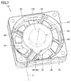
- FIG. 4 is a perspective view showing a wind guide member and a blower in FIG.
- FIG. 5 is a plan view showing a wind guide member and a blower as viewed in the direction indicated by the arrow V in FIG. 6 and 7 are perspective views showing the blower in FIG.
- FIG. 6 shows a blower device 61 on the suction side
- FIG. 7 shows a blower device 61 on the blowout side.
- the blower 61 has a plurality of blade portions 66, a central shaft portion 63, and a motor 62.
- the plurality of blade portions 66 are arranged at intervals from each other in the circumferential direction of the central axis 130, which is a virtual straight line.
- the plurality of blade portions 66 are provided at equal intervals in the circumferential direction of the central axis 130.
- the central shaft 130 extends in the thickness direction of the first housing 31U.
- the axial direction of the central axis 130 corresponds to the thickness direction of the first housing 31U.
- the blower 61 is an axial flow type that sends air in the axial direction of the central axis 130.
- the blower 61 is a propeller fan.
- the blower 61 has a flat plate-like appearance in which the axial direction of the central axis 130 is the thickness direction.
- the end face side of the blower 61 facing in one direction along the axial direction of the central axis 130 corresponds to the suction side, and the end face side of the blower 61 facing in the opposite direction along the axial direction of the central shaft 130 corresponds to the ejection side. are doing.
- the central shaft portion 63 is provided on the axis of the central shaft 130.
- the central shaft portion 63 has a cylindrical shape centered on the central shaft 130.
- the central shaft portion 63 is arranged inside the central shaft 130 in the radial direction with respect to the plurality of blade portions 66.
- the central shaft portion 63 has a first disk portion 64, a second disk portion 67, and a cylindrical portion 65.
- the first disk portion 64 and the second disk portion 67 have a disk shape centered on the central axis 130.
- the first disk portion 64 and the second disk portion 67 are arranged so as to be spaced apart from each other in the axial direction of the central axis 130.
- the first disk portion 64 is arranged on the suction side, and the second disk portion 67 is arranged on the ejection side.
- the cylindrical portion 65 has a cylindrical shape centered on the central axis 130.
- the cylindrical portion 65 is connected to the first disk portion 64 at one end of the central axis 130 in the axial direction.
- the cylindrical portion 65 is separated from the second disk portion 67.
- the root portions of the plurality of blade portions 66 are connected to the cylindrical portion 65.
- the motor 62 is housed in the central shaft portion 63.
- the motor 62 is arranged in a space surrounded by the first disk portion 64, the second disk portion 67, and the cylindrical portion 65.
- the motor 62 is supported by the second disk portion 67.
- the output shaft of the motor 62 is connected to the first disk portion 64.
- the blower 61 further includes a fan guard 70 and a plurality of rib portions 68.
- the fan guard 70 is provided so as to surround the outer periphery of the plurality of blade portions 66.
- the fan guard 70 is provided at a position separated from the central shaft portion 63 on the radial side of the central shaft 130.
- a plurality of blade portions 66 are arranged in the space 72 between the central shaft portion 63 and the fan guard 70 in the radial direction of the central shaft 130.
- a gap is provided between the fan guard 70 and the plurality of blade portions 66 in the radial direction of the central axis 130.
- the plurality of rib portions 68 extend between the fan guard 70 and the central shaft portion 63.
- the plurality of rib portions 68 are arranged so as to be spaced apart from each other in the circumferential direction of the central axis 130.
- the rib portion 68 extends from the inside in the radial direction to the outside in the radial direction of the central axis 130 while being displaced in the circumferential direction of the central axis 130.
- the rib portion 68 is connected to the outer peripheral edge of the second disk portion 67 at the end portion on the inner side in the radial direction of the central axis 130.
- the rib portion 68 is connected to the fan guard 70 at the end portion on the radial outer side of the central axis 130.
- the plurality of rib portions 68 include the rib portions 68j. As shown in FIG. 7, a wiring 71 extending from the motor 62 is arranged in the rib portion 68j.
- the wiring 71 includes the power line and the signal line of the motor 62.
- the wiring 71 is drawn out from the central shaft portion 63 in which the motor 62 is housed to the fan guard 70 through the rib portion 68j.
- the width of the rib portion 68j in the circumferential direction of the central shaft 130 is larger than the width of the rib portion 68 other than the rib portion 68j in the circumferential direction of the central shaft 130.
- the wind guide member 81 has a first flat surface portion 86, an inclined portion 87, and a second flat surface portion 88.
- the first flat surface portion 86 and the second flat surface portion 88 have a flat plate shape in which the axial direction of the central axis 130 is the thickness direction.
- the inclined portion 87 connects the first plane portion 86 and the second plane portion 88.
- the inclined portion 87 has a flat plate shape extending obliquely with respect to the first flat surface portion 86 and the second flat surface portion 88.
- a blower 61 is connected to the first flat surface portion 86.
- the first plane portion 86 extends in a plane direction orthogonal to the central axis 130.
- the blower 61 is provided so as to be stacked in the axial direction of the first plane portion 86 and the central shaft 130.
- the upstream side opening 84 is provided in the first flat surface portion 86.
- the upstream opening 84 opens the air flow path 90 toward the central axis 130 in the axial direction.
- the upstream side opening 84 is open in the axial direction of the central shaft 130 within a range in which the central shaft portion 63 and the space 72 are projected.
- the second plane portion 88 is arranged at a position away from the first plane portion 86 in the radial direction of the central axis 130 and at a position deviated from the first plane portion 86 in the axial direction of the central axis 130.
- the second plane portion 88 extends in the plane direction orthogonal to the central axis 130.
- the downstream side opening 85 is provided in the second flat surface portion 88. The downstream opening 85 opens the air flow path 90 so as to face the radial side of the central axis 130.
- the second flat surface portion 88 is provided at a position deviated from the first flat surface portion 86 in the axial direction of the central axis 130 in a direction approaching the partition wall portion 55.
- the second flat surface portion 88, together with the first flat surface portion 86, has a stepped shape in the axial direction of the central axis 130.
- the blower 61 is arranged in a stepped portion formed by the first flat surface portion 86 and the second flat surface portion 88.
- the inclined portion 87 is arranged between the first plane portion 86 and the second plane portion 88 in the radial direction of the central axis 130.
- the inclined portion 87 extends in an oblique direction with respect to the central axis 130 between the first plane portion 86 and the second plane portion 88.
- the blower 61, the second flat surface portion 88, and the heat sink 47 are provided side by side in the order listed from the inner side in the radial direction to the outer side in the radial direction of the central axis 130.
- the blower 61, the second flat surface portion 88, and the heat sink 47 (a plurality of fins 45) are provided in the same plane orthogonal to the central axis 130.
- the second plane portion 88 is provided so as to face the blower device 61 via the inclined portion 87 in the radial direction of the central axis 130.
- the heat sink 47 (plurality of fins 45) is provided so as to face the second plane portion 88 in the radial direction of the central axis 130.
- the first flat surface portion 86 and the electronic component 43 are provided side by side in the order listed from the inner side in the radial direction to the outer side in the radial direction of the central axis 130.
- the first plane portion 86 and the electronic component 43 are provided in the same plane orthogonal to the central axis 130.
- the electronic component 43 is provided so as to face the electronic component 43 via the inclined portion 87 in the radial direction of the central axis 130.
- the second flat surface portion 88 is provided so as to be stacked with the heat radiating plate 44 in the axial direction of the central axis 130.
- the blower 61, the air guide member 81, the electronic component 43, and the heat sink 47 are formed by utilizing the stepped shape formed by the first flat surface portion 86 and the second flat surface portion 88 of the air guide member 81.
- the first housing 31U can be made thinner.
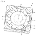
- FIG. 8 is a plan view showing the internal structure of the air guide member.
- FIG. 9 is a cross-sectional view showing a wind guide member seen in the direction of arrow on the IX-IX line in FIG.
- FIG. 10 is a cross-sectional view showing a wind guide member seen in the direction of arrow on the line XX in FIG.
- FIG. 11 is a cross-sectional view showing a wind guide member seen in the direction of arrow on the XI-XI line in FIG.
- FIG. 12 is a cross-sectional view showing a wind guide member seen in the direction of arrow on the XII-XII line in FIG.
- FIG. 13 is a cross-sectional view showing a wind guide member seen in the direction of arrow on the line XIII-XIII in FIG.
- the air flow path 90 has a peripheral portion 90A and a stretched portion 90B.
- the peripheral portion 90A opens in the axial direction of the central axis 130 through the upstream opening portion 84.
- the air sent out from the blower 61 flows into the peripheral portion 90A.
- the stretched portion 90B is arranged on the downstream side of the air flow in the air flow path 90 with respect to the peripheral portion 90A.
- the stretched portion 90B opens outward in the radial direction of the central axis 130 through the downstream opening portion 85.
- the peripheral portion 90A extends in the circumferential direction of the central axis 130.
- the peripheral portion 90A extends in the circumferential direction of the central shaft 130 at a position facing the plurality of blade portions 66 in the axial direction of the central shaft 130.
- the peripheral portion 90A extends in the circumferential direction of the central axis 130 at a position facing the space 72 in the axial direction of the central axis 130.
- the peripheral portion 90A is provided on the first flat surface portion 86.
- the wind guide member 81 (first flat surface portion 86) has a top portion 160, an inner peripheral side wall portion 161 and an outer peripheral side wall portion 162.
- the top 160 has a disk shape centered on the central axis 130.
- the top portion 160 faces the central shaft portion 63 (second disk portion 67) of the blower device 61 in the axial direction of the central shaft 130.
- the inner peripheral side wall portion 161 extends from the peripheral edge portion of the top portion 160 in a direction away from the blower 61 in the axial direction of the central axis 130.
- the inner peripheral side wall portion 161 faces the radial side of the central axis 130 and extends in the circumferential direction of the central axis 130.
- the inner peripheral side wall portion 161 has a constant radius around the central axis 130 regardless of the position in the circumferential direction of the central axis 130.
- the outer peripheral side wall portion 162 faces inward in the radial direction of the central axis 130 and extends in the circumferential direction of the central axis 130.
- the outer peripheral side wall portion 162 faces the inner peripheral side wall portion 161 in the radial direction of the central axis 130.
- the peripheral portion 90A is formed between the inner peripheral side wall portion 161 and the outer peripheral side wall portion 162 in the radial direction of the central axis 130.
- the stretched portion 90B extends from the end of the peripheral portion 90A on the downstream side of the air flow in the air flow path 90 toward the downstream opening portion 85.
- the stretched portion 90B extends from the inside in the radial direction to the outside in the radial direction of the central axis 130.
- the stretched portion 90B is provided on the inclined portion 87 and the second flat surface portion 88.
- the wind guide member 81 (inclined portion 87, second flat surface portion 88) has a first side wall portion 163 and a second side wall portion 164.
- the first side wall portion 163 and the second side wall portion 164 face each other.
- the first side wall portion 163 extends from the wall portion 165, which will be described later, toward the opening edge of the downstream opening 85.
- the second side wall portion 164 extends from the outer peripheral side wall portion 162 toward the opening edge of the downstream side opening 85.
- the stretched portion 90B is formed between the first side wall portion 163 and the second side wall portion 164.
- the distance between the first side wall portion 163 and the second side wall portion 164 increases from the upstream side to the downstream side of the air flow in the air flow path 90.
- the wind guide member 81 (first flat surface portion 86) further has a wall portion 165.
- the wall portion 165 extends between the inner peripheral side wall portion 161 and the first side wall portion 163.
- the wall portion 165 extends from the inside in the radial direction to the outside in the radial direction of the central axis 130 while being displaced in the circumferential direction of the central axis 130.
- the width of the wall portion 165 in the circumferential direction of the central shaft 130 is smaller than the width of the rib portion 68j in the circumferential direction of the central shaft 130.
- the wall portion 165 is arranged at a position overlapping the rib portion 68j when viewed in the axial direction of the central axis 130.
- the wall portion 165 and the rib portion 68j may be configured to partially overlap each other.
- the air flow path 90 has an enlarged flow path portion 150.
- the channel area of the expanded channel portion 150 increases from the upstream side to the downstream side of the air flow.
- the flow path area of the enlarged flow path portion 150 is the opening area of the enlarged flow path portion 150 when cut by a plane orthogonal to the air flow in the air flow path 90.
- the enlarged flow path portion 150 covers the entire range of the peripheral portion 90A and the extending portion 90B. As shown in FIGS. 5 and 8, when viewed in the axial direction of the central axis 130, the enlarged flow path portion 150 surrounds the central axis portion 63 starting from one of the spaces 210 separated by the wall portion 165. It extends and further extends away from the central axis 63 through the other space 220 across the wall 165. The space 210 and the space 220 are provided on both sides of the wall portion 165 when viewed in the axial direction of the central axis 130.
- the direction in which the enlarged flow path portion 150 (circulating portion 90A) orbits around the central axis 130 toward the space 220 with the space 210 as the starting point is the same as the rotation direction of the plurality of blade portions 66 in the blower device 61. Is.
- the enlarged flow path portion 150 is configured such that the flow path area of the air flow path 90 increases from the upstream side to the downstream side of the air flow. The air can flow smoothly.
- the air sent from the blower 61 flows in the axial direction of the central shaft 130, changes the direction in the circumferential direction of the central shaft 130, and the air flow in the air flow path 90. It flows from the upstream side to the downstream side of.
- the flow rate of the air flow in the circumferential portion 90A increases from the upstream side to the downstream side of the air flow in the air flow path 90, so that the pressure on the downstream side of the air flow becomes larger than the pressure on the upstream side.
- the flow path area of the peripheral portion 90A increases from the upstream side to the downstream side of the air flow, the air can flow smoothly in the peripheral portion 90A.
- the air flow rate supplied to the heat sink 47 can be increased to improve the cooling efficiency of the heat sink 47 and, by extension, the electronic component 43.
- the wall portion 165 is provided at a position where the wall portion 165 overlaps with the rib portion 68j which hinders the blowing of air from the blower device 61 to the air flow path 90 when viewed in the axial direction of the central shaft 130. Therefore, the amount of air blown from the air blower 61 to the air flow path 90 can be maintained regardless of the presence or absence of the wall portion 165.
- the enlarged flow path portion 150 (circular portion 90A) has a first section portion 91, a second section portion 92, and a third section portion 93.
- the air sent from the blower 61 flows into the first section 91, the second section 92, and the third section 93 in the axial direction of the central axis 130.
- the second section portion 92 is arranged on the downstream side of the air flow in the air flow path 90 with respect to the first section portion 91.
- the second section 92 is connected to the end of the first section 91 on the downstream side of the air flow in the air flow path 90.
- the third section portion 93 is arranged on the downstream side of the air flow in the air flow path 90 with respect to the second section portion 92.
- the third section 93 is connected to the end of the second section 92 on the downstream side of the air flow in the air flow path 90.
- the first section portion 91 starts from the space 210 and extends over an angle range of less than 90 ° about the central axis 130.
- the flow path area of the enlarged flow path portion 150 in the first section section 91 increases from the upstream side to the downstream side of the air flow (S1 ⁇ S2).
- the flow path depth in the axial direction of the central axis 130 increases from the upstream side to the downstream side of the air flow in the air flow path 90 (H1 ⁇ H2), and the radial direction of the central axis 130.
- the radius of the outer peripheral side wall portion 162 centered on the central axis 130 is constant.
- the distance between the inner peripheral side wall portion 161 and the outer peripheral side wall portion 162 is constant regardless of the position along the air flow direction in the air flow path 90.
- the second section portion 92 extends over an angle range of 90 ° about the central axis 130.
- the flow path area of the enlarged flow path portion 150 in the second section portion 92 increases from the upstream side to the downstream side of the air flow (S2 ⁇ S3).
- the depth of the flow path in the axial direction of the central axis 130 and the width of the flow path in the radial direction of the central axis 130 increase from the upstream side to the downstream side of the air flow in the air flow path 90. (H2 ⁇ H3, B2 ⁇ B3).
- the radius of the outer peripheral side wall portion 162 centered on the central axis 130 increases from the upstream side to the downstream side of the air flow in the air flow path 90.
- the third section portion 93 extends over an angle range of more than 90 ° and less than 180 ° about the central axis 130.
- the flow path area of the enlarged flow path portion 150 in the third section portion 93 increases from the upstream side to the downstream side of the air flow (S3 ⁇ S4 ⁇ S5).
- the radius of the outer peripheral side wall portion 162 centered on the central axis 130 increases from the upstream side to the downstream side of the air flow in the air flow path 90.
- the outer peripheral side wall portion 162 in the second section portion 92 and the third section portion 93 may have a locus extending along a logarithmic spiral when viewed in the axial direction of the central axis 130. It is preferable that the bottom portion of the air flow path 90 is connected to the inner peripheral side wall portion 161 and the outer peripheral side wall portion 162 forming the side portion of the air flow path 90 by a curved surface.
- the angle range of the second section portion 92 centered on the central axis 130 is larger than the angle range of the first section portion 91 centered on the central axis 130.
- the angle range of the third section portion 93 centered on the central axis 130 is larger than the angle range of the second section portion 92 centered on the central axis 130.
- the flow path area of the enlarged flow path portion 150 gradually increases as the flow path depth increases, so that a smooth air flow can be realized. .. Further, since the flow path width is constant in the first section portion 91, the width W of the wind guide member 81 shown in FIG. 8 can be suppressed to a small size. As a result, the wind guide member 81 can be compactly configured.
- the flow path area of the enlarged flow path portion 150 rapidly increases as the flow path depth and the flow path width increase, so that a smoother air flow can be realized.
- the flow path area of the enlarged flow path portion 150 gradually increases as the flow path width increases, so that a smooth air flow can be realized. Further, since the flow path depth is constant in the third section portion 93, the thickness T of the wind guide member 81 shown in FIG. 4 can be suppressed to be small. As a result, the wind guide member 81 can be configured more compactly.
- the operation panel 10 for the machine tool according to the present embodiment accommodates the heat sink 47 as a cooling object.
- An air flow path 90 is formed in the first housing 31U as a housing, the blower 61 arranged in the first housing 31U, and the first housing 31U, and the air sent out from the blower 61 is aired. It is provided with an air guiding member 81 that guides the air flow path 90 toward the heat sink 47.
- the air flow path 90 has an enlarged flow path portion 150 in which the flow path area of the air flow path 90 increases from the upstream side to the downstream side of the air flow.
- the air flow path 90 has an expansion in which the flow path area increases from the upstream side to the downstream side of the air flow.
- blower device in the present invention is an axial flow type
- the present invention is not limited to this, and the blower device in the present invention may be, for example, a sirocco fan or a cross flow. You may be a fan.
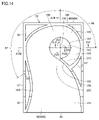
- FIG. 14 is a plan view showing the internal structure of the air guide member of the operation panel according to the second embodiment of the present invention.
- FIG. 14 corresponds to FIG. 8 in the first embodiment.
- FIG. 15 is a cross-sectional view showing a wind guide member seen in the direction of arrow on the XV-XV line in FIG.
- FIG. 16 is a cross-sectional view showing a wind guide member seen in the direction of arrow on the XVI-XVI line in FIG.
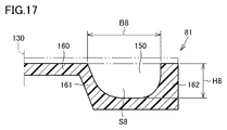
- FIG. 17 is a cross-sectional view showing a wind guide member seen in the direction of arrow on the XVII-XVII line in FIG.
- FIG. 15 is a cross-sectional view showing a wind guide member seen in the direction of arrow on the XV-XV line in FIG.
- FIG. 16 is a cross-sectional view showing a wind guide member seen in the direction of arrow on the XVI-XVI line in FIG.
- FIG. 17 is a cross-sectional view showing
- FIG. 18 is a cross-sectional view showing a wind guide member seen in the direction of arrow on the line XVIII-XVIII in FIG.
- FIG. 19 is a cross-sectional view showing a wind guide member seen in the direction of arrow on the XIX-XIX line in FIG.
- the operation panel in the present embodiment basically has the same structure as the operation panel 10 in the first embodiment. Hereinafter, the description of the overlapping structure will not be repeated.
- the air flow path 90 has a constant flow path portion 155 and an enlarged flow path portion 150.
- the constant flow path portion 155 is provided at a position corresponding to the first section portion 91 of the circumferential portion 90A in the first embodiment.
- the enlarged flow path portion 150 has a position corresponding to the second section portion 92 and the third section portion 93 of the circumferential portion 90A in the first embodiment and the extension portion 90B in the first embodiment. It is provided in.
- the expanded flow path portion 150 (circular portion 90A) has a fourth section portion 96 at a position corresponding to the second section portion 92 of the peripheral portion 90A in the first embodiment.
- the expanded flow path portion 150 (circular portion 90A) has a fifth section portion 97 at a position corresponding to the third section portion 93 of the peripheral portion 90A in the first embodiment.
- the flow path area of the enlarged flow path portion 150 in the fourth section section 96 increases from the upstream side to the downstream side of the air flow (S7 ⁇ S8).
- the flow path area of the enlarged flow path portion 150 in the fifth section portion 97 increases from the upstream side to the downstream side of the air flow (S8 ⁇ S9 ⁇ S10). ).
- the air flow path 90 is composed of a constant flow path portion 155 and an enlarged flow path portion 150, and does not have a section in which the flow path area becomes smaller from the upstream side to the downstream side of the air flow. ..
- the effect described in the first embodiment can be similarly exhibited.
- the present invention is applied to an operation panel used in a machine tool.
Landscapes
- Engineering & Computer Science (AREA)
- Microelectronics & Electronic Packaging (AREA)
- Physics & Mathematics (AREA)
- Thermal Sciences (AREA)
- Mechanical Engineering (AREA)
- Cooling Or The Like Of Electrical Apparatus (AREA)
- Structures Of Non-Positive Displacement Pumps (AREA)
- Machine Tool Units (AREA)
Priority Applications (5)
| Application Number | Priority Date | Filing Date | Title |
|---|---|---|---|
| CN202080106771.2A CN116507448A (zh) | 2020-10-27 | 2020-10-27 | 机床用的操作盘 |
| PCT/JP2020/040203 WO2022091200A1 (ja) | 2020-10-27 | 2020-10-27 | 工作機械用の操作盤 |
| JP2022558632A JP7603081B2 (ja) | 2020-10-27 | 2020-10-27 | 工作機械用の操作盤 |
| EP20959718.6A EP4238694A4 (en) | 2020-10-27 | 2020-10-27 | CONTROL PANEL FOR MACHINE TOOL |
| US18/034,169 US12520449B2 (en) | 2020-10-27 | 2020-10-27 | Operation panel for machine tool |
Applications Claiming Priority (1)
| Application Number | Priority Date | Filing Date | Title |
|---|---|---|---|
| PCT/JP2020/040203 WO2022091200A1 (ja) | 2020-10-27 | 2020-10-27 | 工作機械用の操作盤 |
Publications (1)
| Publication Number | Publication Date |
|---|---|
| WO2022091200A1 true WO2022091200A1 (ja) | 2022-05-05 |
Family
ID=81382186
Family Applications (1)
| Application Number | Title | Priority Date | Filing Date |
|---|---|---|---|
| PCT/JP2020/040203 Ceased WO2022091200A1 (ja) | 2020-10-27 | 2020-10-27 | 工作機械用の操作盤 |
Country Status (5)
| Country | Link |
|---|---|
| US (1) | US12520449B2 (https=) |
| EP (1) | EP4238694A4 (https=) |
| JP (1) | JP7603081B2 (https=) |
| CN (1) | CN116507448A (https=) |
| WO (1) | WO2022091200A1 (https=) |
Citations (8)
| Publication number | Priority date | Publication date | Assignee | Title |
|---|---|---|---|---|
| JPH0438651U (https=) * | 1990-07-27 | 1992-03-31 | ||
| JPH0951189A (ja) * | 1995-05-31 | 1997-02-18 | Sanyo Denki Co Ltd | 電子部品冷却装置 |
| JP2001148589A (ja) * | 1999-11-24 | 2001-05-29 | Pfu Ltd | 冷却ファン付き送風ダクト |
| JP2012222112A (ja) * | 2011-04-07 | 2012-11-12 | Canon Inc | 表示装置およびその放熱方法 |
| JP2012227295A (ja) * | 2011-04-18 | 2012-11-15 | Sony Computer Entertainment Inc | 電子機器 |
| US20130068425A1 (en) * | 2011-09-19 | 2013-03-21 | Chao-Wen Lu | Electronic device and heat dissipation module and centrifugal fan thereof |
| JP2014044816A (ja) * | 2012-08-24 | 2014-03-13 | Panasonic Corp | 薄型誘導加熱調理器 |
| JP2016530658A (ja) | 2013-09-13 | 2016-09-29 | ディエムジー・モリ・アクチェンゲゼルシャフトDmg Mori Aktiengesellschaft | 数値制御工作機械のための制御コンソール |
Family Cites Families (21)
| Publication number | Priority date | Publication date | Assignee | Title |
|---|---|---|---|---|
| JP3404907B2 (ja) | 1994-08-26 | 2003-05-12 | 三菱電機株式会社 | 制御盤 |
| US5689403A (en) * | 1994-12-27 | 1997-11-18 | Motorola, Inc. | Intercooled electronic device |
| US20060181846A1 (en) * | 2005-02-11 | 2006-08-17 | Farnsworth Arthur K | Cooling system for a computer environment |
| US7492590B2 (en) * | 2006-12-15 | 2009-02-17 | Hong Fu Jin Pecision Industry (Shenzhen) Co., Ltd. | Computer enclosure |
| CN102022355B (zh) * | 2009-09-16 | 2013-09-04 | 建准电机工业股份有限公司 | 离心式散热风扇 |
| US9429167B2 (en) * | 2009-10-23 | 2016-08-30 | Sunonwealth Electric Machine Industry Co., Ltd. | Heat dissipating fan |
| US8385065B2 (en) * | 2010-01-19 | 2013-02-26 | Flir Systems, Inc. | Gimbal system with forced flow of external air through a channel to remove heat |
| JP5383740B2 (ja) * | 2011-04-18 | 2014-01-08 | 株式会社ソニー・コンピュータエンタテインメント | 電子機器 |
| BR112013026340B1 (pt) * | 2011-04-18 | 2021-03-23 | Sony Computer Entertainment, Inc | Aparelho eletrônico |
| JP5442683B2 (ja) | 2011-08-23 | 2014-03-12 | レノボ・シンガポール・プライベート・リミテッド | 騒音を軽減した遠心ファン |
| JP5622761B2 (ja) * | 2012-02-22 | 2014-11-12 | 京セラドキュメントソリューションズ株式会社 | 電子機器の吸気機構及びそれを備えた画像形成装置 |
| US9795055B1 (en) * | 2016-04-18 | 2017-10-17 | International Business Machines Corporation | Electronics cooling assembly with multi-position, airflow-blocking mechanism |
| JP6407214B2 (ja) * | 2016-08-02 | 2018-10-17 | 株式会社ソニー・インタラクティブエンタテインメント | 電子機器 |
| US10054993B2 (en) * | 2016-10-05 | 2018-08-21 | Sandisk Enterprise Ip Llc | Airflow guide assembly and enclosure |
| KR102596489B1 (ko) * | 2016-10-10 | 2023-11-01 | 한화비전 주식회사 | 감시 카메라용 냉각장치 |
| US10908270B2 (en) * | 2018-01-18 | 2021-02-02 | Fujifilm Sonosite, Inc. | Portable ultrasound imaging system with active cooling |
| US11109509B2 (en) * | 2019-05-03 | 2021-08-31 | Dell Products, Lp | Cooling module with blower system having dual opposite outlets for information handling systems |
| TWM588906U (zh) * | 2019-09-26 | 2020-01-01 | 藍天電腦股份有限公司 | 筆記型電腦防塵裝置 |
| TWI761944B (zh) * | 2020-01-09 | 2022-04-21 | 宏達國際電子股份有限公司 | 電子裝置 |
| JP7275380B2 (ja) * | 2020-03-27 | 2023-05-17 | 株式会社ソニー・インタラクティブエンタテインメント | 電子機器 |
| JP6934093B1 (ja) * | 2020-07-13 | 2021-09-08 | レノボ・シンガポール・プライベート・リミテッド | 電子機器及び冷却モジュール |
-
2020
- 2020-10-27 US US18/034,169 patent/US12520449B2/en active Active
- 2020-10-27 JP JP2022558632A patent/JP7603081B2/ja active Active
- 2020-10-27 EP EP20959718.6A patent/EP4238694A4/en active Pending
- 2020-10-27 CN CN202080106771.2A patent/CN116507448A/zh active Pending
- 2020-10-27 WO PCT/JP2020/040203 patent/WO2022091200A1/ja not_active Ceased
Patent Citations (8)
| Publication number | Priority date | Publication date | Assignee | Title |
|---|---|---|---|---|
| JPH0438651U (https=) * | 1990-07-27 | 1992-03-31 | ||
| JPH0951189A (ja) * | 1995-05-31 | 1997-02-18 | Sanyo Denki Co Ltd | 電子部品冷却装置 |
| JP2001148589A (ja) * | 1999-11-24 | 2001-05-29 | Pfu Ltd | 冷却ファン付き送風ダクト |
| JP2012222112A (ja) * | 2011-04-07 | 2012-11-12 | Canon Inc | 表示装置およびその放熱方法 |
| JP2012227295A (ja) * | 2011-04-18 | 2012-11-15 | Sony Computer Entertainment Inc | 電子機器 |
| US20130068425A1 (en) * | 2011-09-19 | 2013-03-21 | Chao-Wen Lu | Electronic device and heat dissipation module and centrifugal fan thereof |
| JP2014044816A (ja) * | 2012-08-24 | 2014-03-13 | Panasonic Corp | 薄型誘導加熱調理器 |
| JP2016530658A (ja) | 2013-09-13 | 2016-09-29 | ディエムジー・モリ・アクチェンゲゼルシャフトDmg Mori Aktiengesellschaft | 数値制御工作機械のための制御コンソール |
Non-Patent Citations (1)
| Title |
|---|
| See also references of EP4238694A4 |
Also Published As
| Publication number | Publication date |
|---|---|
| JP7603081B2 (ja) | 2024-12-19 |
| US20230389220A1 (en) | 2023-11-30 |
| JPWO2022091200A1 (https=) | 2022-05-05 |
| EP4238694A1 (en) | 2023-09-06 |
| CN116507448A (zh) | 2023-07-28 |
| EP4238694A4 (en) | 2024-07-31 |
| US12520449B2 (en) | 2026-01-06 |
Similar Documents
| Publication | Publication Date | Title |
|---|---|---|
| US8079788B2 (en) | Machine tool with main body covered with cover | |
| KR20050027937A (ko) | 냉각 장치 및 전자 기기 | |
| JP4792103B2 (ja) | 遠心ファンおよび電子機器 | |
| JP4793325B2 (ja) | 遠心ファン装置及びそれを備えた電子機器 | |
| US8933600B2 (en) | Brushless DC motor structure having a fan radiator for dissipating heat from the motor and the controller | |
| CN111526971A (zh) | 电动工具 | |
| KR101394499B1 (ko) | 팬 모듈 | |
| US20240141922A1 (en) | Heat dissipation system of electronic device | |
| WO2019176563A1 (ja) | 流体機械 | |
| KR20040101528A (ko) | 원심 송풍기 및 원심 송풍기를 구비한 공기 조화 장치 | |
| JP4099458B2 (ja) | 静翼を含む遠心ファン | |
| CN107053095A (zh) | 电动工具 | |
| CN215392873U (zh) | 交流无刷切割工具 | |
| JP7353742B2 (ja) | 流体機械 | |
| JPWO2021193879A5 (https=) | ||
| JP7603081B2 (ja) | 工作機械用の操作盤 | |
| JP7425893B2 (ja) | 工作機械用の操作盤 | |
| CN115870553A (zh) | 手持式电圆锯 | |
| JP6694094B2 (ja) | パッケージ形圧縮機 | |
| WO2021210097A1 (ja) | 流体機械 | |
| CN114054847A (zh) | 动力工具 | |
| TWM657554U (zh) | 電動研磨工具機 | |
| JP2001111277A (ja) | 遠心ファンとそれを用いた電子機器 | |
| JP2000124648A (ja) | ヒートシンクファン装置 | |
| CN115365573A (zh) | 手持式电圆锯 |
Legal Events
| Date | Code | Title | Description |
|---|---|---|---|
| 121 | Ep: the epo has been informed by wipo that ep was designated in this application |
Ref document number: 20959718 Country of ref document: EP Kind code of ref document: A1 |
|
| ENP | Entry into the national phase |
Ref document number: 2022558632 Country of ref document: JP Kind code of ref document: A |
|
| WWE | Wipo information: entry into national phase |
Ref document number: 18034169 Country of ref document: US Ref document number: 202080106771.2 Country of ref document: CN |
|
| NENP | Non-entry into the national phase |
Ref country code: DE |
|
| ENP | Entry into the national phase |
Ref document number: 2020959718 Country of ref document: EP Effective date: 20230530 |
|
| WWG | Wipo information: grant in national office |
Ref document number: 18034169 Country of ref document: US |