WO2022091171A1 - マクロフロー生成装置、マクロフロー生成方法及びプログラム - Google Patents
マクロフロー生成装置、マクロフロー生成方法及びプログラム Download PDFInfo
- Publication number
- WO2022091171A1 WO2022091171A1 PCT/JP2020/040060 JP2020040060W WO2022091171A1 WO 2022091171 A1 WO2022091171 A1 WO 2022091171A1 JP 2020040060 W JP2020040060 W JP 2020040060W WO 2022091171 A1 WO2022091171 A1 WO 2022091171A1
- Authority
- WO
- WIPO (PCT)
- Prior art keywords
- macro flow
- macro
- flow
- quality
- flows
- Prior art date
- Legal status (The legal status is an assumption and is not a legal conclusion. Google has not performed a legal analysis and makes no representation as to the accuracy of the status listed.)
- Ceased
Links
Images


Classifications
-
- H—ELECTRICITY
- H04—ELECTRIC COMMUNICATION TECHNIQUE
- H04L—TRANSMISSION OF DIGITAL INFORMATION, e.g. TELEGRAPHIC COMMUNICATION
- H04L45/00—Routing or path finding of packets in data switching networks
- H04L45/38—Flow based routing
Definitions
- the present invention relates to a macro flow generator, a macro flow generation method and a program.
- SDN Software Defined Network
- OpenFlow OpenFlow
- a flow is defined by arbitrarily combining header information such as a departure / arrival IP address, a departure / arrival port number, and a protocol number, and it is possible to control a route in units of flows.
- the controller can centrally control each node in the network by software, it is possible to realize control with finer particle size and shorter time cycle than conventional traffic control such as OSPF.
- Non-Patent Document 1 a macro flow is generated so that the time-series fluctuation of the communication amount becomes small. Further, in Non-Patent Document 1, a macro flow is generated so that the access pattern (required communication quality) is similar.
- the above-mentioned conventional technique for generating macro flows can generate macro flows, but the required communication quality (required bandwidth, required delay, etc.) for each macro flow is not estimated.
- the traffic control technique (for example, Patent Document 2) calculates the route allocation so as to satisfy the required communication quality of the control unit. Therefore, if the required communication quality for each macro flow is not clear, route allocation is performed without considering the required communication quality, and the communication quality of the flow may be significantly deteriorated. Therefore, as a method of estimating the required communication quality of the macro flow from the required communication quality of the micro flow, in Non-Patent Document 2, the statistical values (average value, median value, maximum value) of the required communication quality of the micro flow constituting the macro flow are described. A method has been proposed in which the minimum value, percentile value, etc.) are used as the required communication quality of the macro flow.
- the present invention has been made in view of the above points, and an object of the present invention is to generate a macro flow that reduces the possibility of route allocation that causes deterioration of communication quality.
- the macro flow generator is a plurality of individual flows collected from the respective terminals for each individual flow of the plurality of terminals using the service provided via the network.
- a macro flow generator that divides a set of the plurality of individual flows into macro flows each including one or more of the flows based on the similarity of required quality, and each macro flow belongs to the macro flow. It has a macro flow required quality calculation unit that calculates the required quality of the macro flow based on the required quality of one or more individual flows.
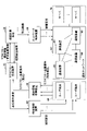
- FIG. 1 is a diagram showing an example of a system configuration according to an embodiment of the present invention.
- a communication network N1 one or more user terminals 60, one or more servers 70, a terminal information collection device 20, a macroflow generation device 10, a route calculation device 30, a terminal control device 40, a network control device 50, and the like are shown. It is shown.
- the communication network N1 is a communication network that transfers traffic in communication between the user terminal 60 and the server 70. As shown in FIG. 2, the communication network N1 includes a plurality of communication devices 80.
- the communication device 80 is a device that transfers traffic such as a router or a switch.
- the user terminal 60 and the server 70 are devices that are the source or destination of traffic.
- the server 70 is a computer that provides a service provided by a service provider to a user terminal 60 via a communication network N1.
- the user terminal 60 is a terminal used by a user of the service (for example, a PC (Personal Computer), a tablet terminal, a smartphone, or the like).
- the application of the service provider linked with the network operator is installed in the user terminal 60.
- the application acquires quality requirements for each microflow.
- the micro flow means an individual flow defined by an arbitrary combination of header information such as a departure / arrival IP address, a departure / arrival port number, and a protocol number in SDN (Software Defined Network).
- SDN Software Defined Network
- the terminal information collecting device 20 is a device that collects quality requirements for each microflow acquired by the user terminal 60 (application) from each user terminal 60.
- the quality requirement refers to a requirement desired by the user of the user terminal 60 regarding the quality of service (or the quality of communication related to the service).
- the macro flow generation device 10 is one or more computers that calculate (estimate) the generation of macro flow and the required quality of macro flow based on the quality requirements of each micro flow collected by the terminal information collecting device 20.
- the macro flow generation device 10 transmits information indicating the micro flow constituting each generated macro flow (hereinafter referred to as “macro flow configuration information”) and the required quality of the macro flow to the route calculation device 30.
- the route calculation device 30 calculates the route to be assigned to each macro flow (executes route allocation in macro flow units) with the macro flow configuration information and the required quality of each macro flow as requirements. For example, the technique proposed in Patent Document 2 or the like may be applied to the route calculation device 30.
- the route calculation device 30 notifies the macro flow generation device 10 of the route allocation result indicating the success or failure of the route allocation in macro flow units.
- the macro flow generator 10 regenerates (reconfigures) the macro flow so that the probability of successful route allocation increases when the route allocation result indicates that the route allocation cannot satisfy the required quality of all macro flows. )do.
- the macroflow generator 10 may include some or all micros. Control to change the quality requirements of the flow. Specifically, the macro flow generation device 10 requests the terminal control device 40 to change (decrease) the quality requirement of a part or all of the micro flow.
- the terminal control device 40 requests the application of each user terminal 60 to change the quality requirement of the micro flow in response to the change request of the quality requirement of the micro flow from the macro flow generation device 10. By doing so, the traffic of services that require high quality can be reduced, and the probability of successful route allocation can be increased.
- the network control device 50 sets the traffic transfer information in each communication device 80 based on the macro flow allocation route calculated by the route calculation device 30.
- the communication network N1 is based on the conventional techniques for macro flow generation (Patent Document 1, Non-Patent Document 1) and macro flow required quality estimation (Non-Patent Document 2). Macroflow control may be executed using the traffic information that can be acquired from within.
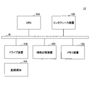
- FIG. 2 is a diagram showing a hardware configuration example of the macro flow generator 10 according to the embodiment of the present invention.
- the macro flow generation device 10 of FIG. 2 has a drive device 100, an auxiliary storage device 102, a memory device 103, a CPU 104, an interface device 105, and the like, which are connected to each other by a bus B, respectively.
- the program that realizes the processing in the macro flow generation device 10 is provided by a recording medium 101 such as a CD-ROM.
- a recording medium 101 such as a CD-ROM.
- the program is installed in the auxiliary storage device 102 from the recording medium 101 via the drive device 100.
- the program does not necessarily have to be installed from the recording medium 101, and may be downloaded from another computer via the network.
- the auxiliary storage device 102 stores the installed program and also stores necessary files, data, and the like.
- the memory device 103 reads a program from the auxiliary storage device 102 and stores it when there is an instruction to start the program.
- the CPU 104 executes the function related to the macro flow generation device 10 according to the program stored in the memory device 103.
- the interface device 105 is used as an interface for connecting to a network.
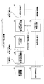
- FIG. 3 is a diagram showing a functional configuration example of the macro flow generator 10 according to the embodiment of the present invention.
- the macro flow generation device 10 includes a micro flow requirement quality calculation unit 11, a macro flow generation unit 12, a macro flow requirement quality calculation unit 13, a macro flow regeneration unit 14, and the like. Each of these parts is realized by a process of causing the CPU 104 to execute one or more programs installed in the macro flow generation device 10.
- the microflow requirement quality calculation unit 11 calculates (generates) microflow requirement quality information from the microflow quality requirement.
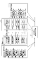
- FIG. 4 is a diagram for explaining the process executed by the microflow requirement quality calculation unit 11.
- the microflow quality requirement includes, for each microflow, the service type used by the microflow, the target QoE (Quality of Experience) value of the microflow, and the like. Information.
- the service type is the type of service provided in the micro flow.
- the QoE value is a numerical value indicating the high quality of the user's experience regarding the service. In the example of FIG. 4, the QoE value is evaluated in 5 stages, and the higher the value, the better the quality.
- Voice phone (“The E-model: a Computational model for use in transmission planning, Recommendation ITU-T G.107, 2015”), videophone (“Opinion model for video-telephony applications, Recommendation ITU-T G.1070,”) 2018 ”), Adaptive Bitrate (ABR) video distribution (“Parametric bitstream-based quality assessment of progressive, download and adaptive audiovisual streaming services over reliable transport, Recommendation ITU-T P.1203, 2017”) Is standardized and corresponds to what is called the MOS value.
- ABR Adaptive Bitrate
- the target QoE value is a QoE value indicating the quality level required by the user, and the higher the value, the higher the quality service requested by the user. For example, a high target QoE value is set for a user who cannot be satisfied with a high-quality video, and a low target QoE value is set for a user who thinks that it is sufficient to understand the content even with a low-quality video.
- the microflow required quality information is information including the required quality for each microflow (required bandwidth, required delay, etc. in the example of FIG. 4).
- FIG. 4 shows a method using the conversion table T1.
- the conversion table T1 is stored in, for example, the auxiliary storage device 102.
- the conversion table T1 stores information on the correspondence between the input and the output when the set of the service type and the target QoE value is used as the input and the required required quality is used as the output.
- the microflow requirement quality calculation unit 11 uses the conversion table T1 to specify the required quality for each microflow quality requirement included in the input microflow requirement quality information (converts the microflow quality requirement into a quality requirement). ),
- the microflow required quality information including the specified required quality group is output to the macroflow generation unit 12.
- Various methods can be considered for the configuration method of the conversion table T1.
- a method in which a network operator cooperates with a service provider and configures a conversion table T1 based on information provided by the service provider can be considered.
- a method using a technique (Patent Document 3) that models the relationship between the throughput and QoE can be considered.
- This technique is a technique for estimating QoE by using a throughput as an input, and by using the correspondence between the throughput of this model and QoE, the corresponding throughput may be derived from QoE and the conversion table T1 may be configured.
- the microflow quality requirement collected from the user terminal 60 may include the required quality (required bandwidth, required delay, etc. in the example of FIG. 4) instead of the target OoE value.
- the microflow required quality calculation unit 11 may simply summarize the required qualities of each microflow to generate the microflow required quality information.
- the macro flow generation unit 12 divides a set of a plurality of micro flows into macro flows based on the similarity of the required quality based on the micro flow required quality information output from the micro flow required quality calculation unit 11, and shows the division result. Generate macro flow configuration information. Specifically, the macro flow generation unit 12 aggregates micro flows having similar required qualities into the same macro flow.
- FIG. 5 is a diagram for explaining the process executed by the macro flow generation unit 12.
- the macro flow configuration information includes, for each macro flow, the required quality of each micro flow that constitutes the macro flow (aggregated in the macro flow).
- the macroflow configuration information of FIG. 5 an example in which the microflow group is divided into three macroflows based on the similarity of the required bandwidth and the required delay is shown.
- the macroflow generation unit 12 applies an existing clustering technique such as the K-means clustering method to the required quality of each microflow to convert the microflow group into a macroflow (aggregate microflows having similar required quality). You may. That is, in this case, the macro flow generation unit 12 aggregates the micro flow groups classified into the same cluster into the same macro flow.
- FIG. 5 shows an example in which clustering is performed for a microflow group in a two-dimensional space sp1 of a required band and a required delay constituting the required quality.
- the numbers in parentheses indicate the identification numbers of the microflow.
- (1) shows microflow 1.
- the macro flow generation unit 12 outputs the generated macro flow configuration information to the macro flow requirement quality calculation unit 13.
- the macro flow requirement quality calculation unit 13 refers to the macro flow configuration information output from the macro flow generation unit 12, and requests the macro flow based on the requirement quality of each micro flow group constituting the macro flow for each macro flow. Calculate (estimate) quality.
- the macro flow generation unit 12 generates macro flow required quality information based on the calculation result, and outputs the macro flow required quality information.
- FIG. 6 is a diagram for explaining the process executed by the macro flow requirement quality calculation unit 13.
- the macro flow required quality information is information including the calculation result of the required quality for each macro flow in addition to the macro flow configuration information.
- the macro flow requirement quality calculation unit 13 has statistical values (average value, median value, maximum / minimum value, percentile value, etc.) of the required quality of the micro flow constituting the macro flow. ) Is the required communication quality of the macro flow.
- FIG. 6 shows an example in which the required band of the macro flow is the total value of the required band of the micro flow constituting the macro flow, and the required delay of the macro flow is the minimum value of the required delay of the micro flow.
- the macro flow requirement quality calculation unit 13 transmits the macro flow requirement quality information to the route calculation device 30.
- the macro flow regeneration unit 14 receives the route allocation result from the route calculation device 30, and regenerates the macro flow when the route allocation result indicates an allocation failure.
- the macro flow regeneration unit 14 also transmits a request for changing the quality requirement of the user terminal 60 to the terminal control device 40.
- FIG. 7 is a diagram for explaining the process executed by the macro flow regeneration unit 14.
- the route allocation result includes a "result” indicating the success or failure of the allocation and the macro flow request quality information used for the route allocation.
- the macro flow regeneration unit 14 first regenerates (reconstructs) the macro flow.
- route allocation tends to fail in a network with few surplus physical resources. Therefore, the macro flow regeneration unit 14 performs a plurality of macro flows with a relatively large request band. Regenerate the macro flow by splitting it into. That is, the macro flow having a relatively high required quality is preferentially divided.
- the macro flow regeneration unit 14 generates macro flow configuration information related to the regenerated macro flow, and outputs the macro flow configuration information to the macro flow requirement quality calculation unit 13.
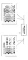
- FIG. 7 shows the macro flow configuration information when the macro flow 1 having the largest required bandwidth in the macro flow request quality information of the route allocation result is divided into two macro flows, macro flow 1 and macro flow 4. Has been done.
- the minimum unit for dividing a macro flow is a micro flow. Therefore, the macro flow 1 after the division belongs to the micro flow 1, and the macro flow 4 belongs to the micro flow 3.
- FIG. 8 is a flowchart for explaining an example of the processing procedure of the macro flow regeneration processing.
- step S101 the macro flow regeneration unit 14 arranges all the macro flows related to the macro flow request quality information included in the route allocation result in descending order of the request band of each macro flow.
- the macro flow regeneration unit 14 substitutes 1 for the variable i (S102).
- the variable i is a variable in which the order of the macro flow to be processed is stored after the alignment.
- the i-th macro flow is referred to as "macro flow i".
- the macro flow regeneration unit 14 assigns 2 to the variable j (S103).
- the variable j is a variable in which the number of divisions of the macro flow i is stored. That is, in the present embodiment, the initial value of the number of divisions of each macro flow is 2.
- the macroflow regeneration unit 14 divides the macroflow i into j macroflows so that the required bandwidth of each macroflow after division is as uniform as possible (S104).
- each macro flow after division means each macro flow newly generated by the division of the micro flow group constituting the macro flow i.
- the minimum unit of division is the microflow constituting the macroflow i. Therefore, the required bandwidth of each macro flow after division may not completely match. Therefore, the macro flow regeneration unit 14 divides the macro flow i into j macro flows so that the total sum of the differences in the required bands of the divided macro flows is minimized, for example.
- the macroflow regeneration unit 14 includes the required quality of each microflow constituting the macroflow for each macroflow after division, and each microflow constituting the macroflow for each undivided macroflow.
- the macro flow configuration information including the required quality of is output to the macro flow required quality calculation unit 13 (S105).
- the macro flow requirement quality calculation unit 13 calculates the requirement quality of each macro flow based on the macro flow configuration information, and the macro flow requirement quality information which is the calculation result is transmitted to the route calculation device 30.
- the route calculation device 30 calculates the route to be assigned to each macro flow based on the macro flow request quality information, and transmits the route allocation result to the macro flow regeneration unit 14.
- the macro flow regeneration unit 14 determines whether or not the "result" of the route allocation result is a value indicating the success of the route allocation (S106). When the "result" is a value indicating the success of route allocation (Yes in S106), the macro flow regeneration unit 14 ends the process. On the other hand, when the "result” is a value indicating a route allocation failure (No in S106), the macro flow regeneration unit 14 adds 1 to j (S107), and the value of j is equal to or less than a preset threshold value. It is determined whether or not it is (S108). The reason why the threshold value (upper limit) is set for the number of divisions of the macro flow is that if the number of divisions of the macro flow is too large, the significance of treating the route control or the like as a macro flow unit is diminished.
- the macro flow regeneration unit 14 repeats steps S104 and subsequent steps.
- the macroflow regeneration unit 14 adds 1 to i (S109).
- the macro flow regeneration unit 14 determines whether or not the value of i is equal to or less than the number of macro flows related to the macro flow request quality information of the route allocation result (S110).
- the macro flow regeneration unit 14 repeats steps S103 and subsequent steps.
- it is executed for each macro flow at the beginning (at the time of step S101). That is, the macro flow generated by the division of any of the initial macro flows is not subject to the processing of step S103.
- the macro flow regeneration unit 14 ends the process. In this case (ie, if all the original macroflows are split up to the upper limit), the current quality requirements for microflows are that no matter how the macroflows are regenerated (reconstructed), routing will not succeed. , The macro flow regeneration unit 14 transmits the quality requirement change to the application of each user terminal 60 via the terminal control device 40.
- the quality requirement change is information indicating an instruction on how to change the quality requirement of the user terminal 60.
- quality requirements there are various possible changes in quality requirements, but in Fig. 7 , relatively high quality is required so that the target QoE value of the microflow, which is set to 5 as the target QoE value, is lowered to 4.
- An example is a method of preferentially reducing the traffic of the service being provided.
- the target QoE is not lowered so that it is below the contracted bandwidth of the user who has contracted the bandwidth reservation type plan, and the target QoE of the user who has contracted the best effort type plan is given priority.
- Quality requirement changes may be generated based on techniques such as lowering.
- the route allocation that causes the deterioration of the communication quality is used. Can generate macroflows that reduce the likelihood that Further, even if the route allocation fails, the macro flow is reconstructed, so that the deterioration of the communication quality can be further suppressed. As a result, it can be expected that the user's experience quality will be improved.
- control is performed to reduce the quality requirements of a part or all of the plurality of micro flows. In that respect as well, it is possible to generate a macro flow that reduces the possibility that route allocation that causes deterioration of communication quality is performed.
Landscapes
- Engineering & Computer Science (AREA)
- Computer Networks & Wireless Communication (AREA)
- Signal Processing (AREA)
- Data Exchanges In Wide-Area Networks (AREA)
Abstract
マクロフロー生成装置は、ネットワークを介して提供されるサービスを利用する複数の端末のそれぞれの個別のフローについて前記各端末から収集される、複数の前記個別のフローの要求品質の類似性に基づいて、前記複数の個別のフローの集合を、それぞれが1以上の前記フローを含むマクロフローに分割するマクロフロー生成部と、前記マクロフローごとに、当該マクロフローに属する1以上の前記個別のフローの要求品質に基づいて当該マクロフローの要求品質を計算するマクロフロー要求品質計算部と、を有することで、通信品質の低下を招く経路割当が実施される可能性を低下させるマクロフローを生成する。
Description
本発明は、マクロフロー生成装置、マクロフロー生成方法及びプログラムに関する。
近年、通信ネットワークでは、OpenFlowに代表されるSDN(Software Defined Network)技術が導入されつつある。SDNでは、発着IPアドレス、発着ポート番号、プロトコル番号等のヘッダ情報を任意に組合せたものでフローが定義され、フロー単位での経路の制御が可能である。また、コントローラがネットワーク内の各ノードをソフトウェア的に集中制御できるため、OSPFなどの従来のトラヒック制御よりも、細かい粒度で、かつ、短い時間周期での制御を実現できる。
一方で、各ノードやコントローラは、フロー単位の経路情報を保持する必要があり、管理すべき情報数が膨大となるため、大規模ネットワークへのSDNの適用が困難となってしまう。そのため、個別フローよりも大きく、かつ、ネットワークアドレスが同一な粒度よりは小さな粒度でトラヒックを制御する技術が提案されている(例えば、特許文献1、非特許文献1)。具体的には、同一発着ネットワークアドレスを有するフロー集合から一部のフロー群を集約し、集約したフロー群の単位で経路を制御する。以降、個別フローを「ミクロフロー」といい、集約したフロー群を「マクロフロー」という。
特許文献1の技術では、通信量の時系列変動が小さくなるようにマクロフローが生成される。また、非特許文献1では、アクセスパターン(要求通信品質)が類似するようにマクロフローが生成される。
駒井友香, 木村達明, 小林正裕, 原田薫明、"アクセスパターンに基づいたトラヒック予測手法"、信学技報, vol. 119, no. 158, IN2019-22, pp. 43-46, 2019年8月
小林ら、"サービス要求通信品質に基づくネットワーク制御技術"、IEICE総合大会、2020年3月
上記のマクロフローの生成に関する従来技術は、マクロフローを生成できるが、マクロフロー毎の要求通信品質(要求帯域,要求遅延など)は推定されない。トラヒック制御技術(例えば、特許文献2)は、制御単位の要求通信品質を満たすように経路割当を計算する。したがって、マクロフロー毎の要求通信品質が明らかでない場合は、要求通信品質を考慮しない経路割当が行われ、フローの通信品質が大きく低下してしまう可能性がある。そのため、ミクロフローの要求通信品質からマクロフローの要求通信品質を推定する方法として、非特許文献2では、マクロフローを構成するミクロフローの要求通信品質の統計値(平均値,中央値,最大・最小値,パーセンタイル値など)を、マクロフローの要求通信品質とする手法が提案されている。
マクロフローの生成、マクロフローの要求品質の推定、トラヒック制御に関する従来技術を組み合わせれば、マクロフローに基づくネットワーク制御が可能となる。しかし、これらはネットワーク内から取得できるトラヒック情報に基づき端末及びユーザの状態に基づいて実行さるため、通信品質の低下を招く経路割当が実施される可能性が有る。
本発明は、上記の点に鑑みてなされたものであって、通信品質の低下を招く経路割当が実施される可能性を低下させるマクロフローを生成することを目的とする。
そこで上記課題を解決するため、マクロフロー生成装置は、ネットワークを介して提供されるサービスを利用する複数の端末のそれぞれの個別のフローについて前記各端末から収集される、複数の前記個別のフローの要求品質の類似性に基づいて、前記複数の個別のフローの集合を、それぞれが1以上の前記フローを含むマクロフローに分割するマクロフロー生成部と、前記マクロフローごとに、当該マクロフローに属する1以上の前記個別のフローの要求品質に基づいて当該マクロフローの要求品質を計算するマクロフロー要求品質計算部と、を有する。
通信品質の低下を招く経路割当が実施される可能性を低下させるマクロフローを生成することができる。
以下、図面に基づいて本発明の実施の形態を説明する。図1は、本発明の実施の形態におけるシステム構成例を示す図である。図1には、通信ネットワークN1、1以上のユーザ端末60、1以上のサーバ70、端末情報収集装置20、マクロフロー生成装置10、経路計算装置30、端末制御装置40及びネットワーク制御装置50等が示されている。
通信ネットワークN1は、ユーザ端末60とサーバ70との通信におけるトラヒックを転送する通信網である。図2に示されるように、通信ネットワークN1は、複数の通信装置80を含む。通信装置80は、ルータやスイッチなどのトラヒックを転送する装置である。
ユーザ端末60及びサーバ70はトラヒックの送信元又は送信先となる装置である。サーバ70は、サービス事業者によるサービスを、通信ネットワークN1を介してユーザ端末60に提供するコンピュータである。ユーザ端末60は、サービスのユーザが利用する端末(例えば、PC(Personal Computer)、タブレット端末又はスマートフォン等)である。ユーザ端末60には、ネットワーク事業者と連携しているサービス事業者のアプリケーションがインストールされている。当該アプリケーションは、ミクロフロー毎の品質要件を取得する。なお、本実施の形態において、ミクロフローとは、SDN(Software Defined Network)において、発着IPアドレス、発着ポート番号、プロトコル番号等のヘッダ情報を任意に組合せによって定義される個別のフローをいう。一方、同一発着ネットワークアドレスを有するフロー集合から一部のフロー群を集約したフロー群を「マクロフロー」という。
端末情報収集装置20は、ユーザ端末60(のアプリケーション)が取得したミクロフロー毎の品質要件を各ユーザ端末60から収集する装置である。品質要件とは、サービスの品質(又はサービスに係る通信の品質)について、ユーザ端末60のユーザが所望する要件をいう。
マクロフロー生成装置10は、端末情報収集装置20によって収集された各ミクロフローの品質要件に基づき、マクロフローの生成及びマクロフローの要求品質を計算(推定)する1以上のコンピュータである。マクロフロー生成装置10は、生成した各マクロフローを構成するミクロフローを示す情報(以下、「マクロフロー構成情報」という。)とマクロフローの要求品質とを経路計算装置30へ送信する。
経路計算装置30は、マクロフロー構成情報及び各マクロフローの要求品質を要求条件とし、各マクロフローに割り当てる経路を計算する(マクロフロー単位での経路割当を実行する)。例えば、特許文献2などで提案されている技術が経路計算装置30に適用されてもよい。経路計算装置30は、マクロフロー単位での経路割当の成否を示す経路割当結果をマクロフロー生成装置10へ結果を通知する。マクロフロー生成装置10は、経路割当結果が全てのマクロフローの要求品質を満たすような経路割当ができないことを示す場合、経路割当の成功の可能性が高まるようにマクロフローを再生成(再構成)する。もし、ネットワークリソースが逼迫し、現在のミクロフローの品質要件では、どのようにマクロフローを再生成しても経路割当が成功しないような場合、マクロフロー生成装置10は、一部又は全部のミクロフローの品質要件を変更させるための制御を行う。具体的には、マクロフロー生成装置10は、一部又は全部のミクロフローの品質要件の変更(低下)を端末制御装置40に要求する。
端末制御装置40は、マクロフロー生成装置10からのミクロフローの品質要件の変更要求に応じ、各ユーザ端末60のアプリケーションに対して、ミクロフローの品質要件の変更を要求する。そうすることで、高い品質を要求しているサービスのトラヒックを低減させることができ、経路割当が成功する可能性を高めることができる。
ネットワーク制御装置50は、経路計算装置30によって計算された、マクロフローの割当経路に基づき、各通信装置80にトラヒックの転送情報を設定する。なお、ユーザ端末60からのフィードバックが得られないトラヒックについては、マクロフロー生成(特許文献1、非特許文献1)、マクロフロー要求品質推定(非特許文献2)についての従来技術により、通信ネットワークN1内から取得できるトラヒック情報を用いてマクロフロー制御が実行されてもよい。
図2は、本発明の実施の形態におけるマクロフロー生成装置10のハードウェア構成例を示す図である。図2のマクロフロー生成装置10は、それぞれバスBで相互に接続されているドライブ装置100、補助記憶装置102、メモリ装置103、CPU104、及びインタフェース装置105等を有する。
マクロフロー生成装置10での処理を実現するプログラムは、CD-ROM等の記録媒体101によって提供される。プログラムを記憶した記録媒体101がドライブ装置100にセットされると、プログラムが記録媒体101からドライブ装置100を介して補助記憶装置102にインストールされる。但し、プログラムのインストールは必ずしも記録媒体101より行う必要はなく、ネットワークを介して他のコンピュータよりダウンロードするようにしてもよい。補助記憶装置102は、インストールされたプログラムを格納すると共に、必要なファイルやデータ等を格納する。
メモリ装置103は、プログラムの起動指示があった場合に、補助記憶装置102からプログラムを読み出して格納する。CPU104は、メモリ装置103に格納されたプログラムに従ってマクロフロー生成装置10に係る機能を実行する。インタフェース装置105は、ネットワークに接続するためのインタフェースとして用いられる。
図3は、本発明の実施の形態におけるマクロフロー生成装置10の機能構成例を示す図である。図3において、マクロフロー生成装置10は、ミクロフロー要求品質計算部11、マクロフロー生成部12、マクロフロー要求品質計算部13及びマクロフロー再生成部14等を有する。これら各部は、マクロフロー生成装置10にインストールされた1以上のプログラムが、CPU104に実行させる処理により実現される。
[ミクロフロー要求品質計算部11]
ミクロフロー要求品質計算部11は、ミクロフロー品質要件からミクロフロー要求品質情報を計算(生成)する。
ミクロフロー要求品質計算部11は、ミクロフロー品質要件からミクロフロー要求品質情報を計算(生成)する。
図4は、ミクロフロー要求品質計算部11が実行する処理を説明するための図である。図4に例示されているように、ミクロフロー品質要件は、ミクロフローごとに、当該ミクロフローが利用するサービス種別、及び当該ミクロフローの目標QoE(Quality of Experience:ユーザ体感品質)値等を含む情報である。
サービス種別は、ミクロフローにおいて提供されるサービスの種別である。
QoE値は、サービスに関するユーザの体感品質の高さを表す数値である。図4の例において、QoE値は、5段階で評価され、数値が高いほど品質が良いことを示す。音声電話(「The E-model: a computational model for use in transmission planning, Recommendation ITU-T G.107, 2015」)、テレビ電話(「Opinion model for video-telephony applications, Recommendation ITU-T G.1070, 2018」)、アダプティブビットレート(ABR)映像配信(「Parametric bitstream-based quality assessment of progressive, download and adaptive audiovisual streaming services over reliable transport, Recommendation ITU-T P.1203, 2017」)などのサービスでは品質評価が標準化されており、その中でMOS値と呼ばれているものに相当する。
目標QoE値は、ユーザが要求する品質水準を表すQoE値であり、高いほど高品質なサービスをユーザが要求していることを示す。例えば、高画質な動画でなければ満足できないユーザに対する目標QoE値が高く設定され、低画質な動画でも内容が理解できれば十分と考えるユーザに対する目標QoE値は低く設定される。
一方、ミクロフロー要求品質情報は、ミクロフロー毎の要求品質(図4の例では要求帯域、要求遅延など)を含む情報である。
ミクロフロー品質要件からミクロフロー要求品質情報の計算については、様々な手法が考えられるが、図4では変換テーブルT1を用いる方法が示されている。変換テーブルT1は、例えば、補助記憶装置102に記憶されている。変換テーブルT1には、サービス種別及び目標QoE値の組を入力とし、必要な要求品質を出力とした場合における、入力と出力との対応情報が記憶されている。ミクロフロー要求品質計算部11は、変換テーブルT1を用いて、入力されるミクロフロー要求品質情報に含まれる各ミクロフロー品質要件に対する要求品質を特定し(当該ミクロフロー品質要件を品質要件へ変換し)、特定した要求品質群を含むミクロフロー要求品質情報をマクロフロー生成部12へ出力する。
変換テーブルT1の構成方法についても、様々な方法が考えられる。一例として、ネットワーク事業者が、サービス事業者と連携し、サービス事業者から提供される情報に基づいて変換テーブルT1を構成する方法が考えられる。他にも、スループットとQoEの関係をモデル化した技術(特許文献3)を用いる方法が考えられる。この技術は、スループットを入力とし、QoEを推定する技術であり、このモデルのスループットとQoEの対応関係を利用することで、QoEから対応するスループットを導き、変換テーブルT1を構成してもよい。
但し、ユーザ端末60から収集されるミクロフロー品質要件には、目標OoE値の代わりに要求品質(図4の例では要求帯域、要求遅延など)が含まれていてもよい。この場合、ミクロフロー要求品質計算部11は、各ミクロフローの要求品質を単純にまとめてミクロフロー要求品質情報を生成すればよい。
[マクロフロー生成部12]
マクロフロー生成部12は、ミクロフロー要求品質計算部11から出力されるミクロフロー要求品質情報に基づき、複数のミクロフローの集合を要求品質の類似性に基づきマクロフローに分割し、分割結果を示すマクロフロー構成情報を生成する。具体的には、マクロフロー生成部12は、要求品質が類似するミクロフローを同一のマクロフローに集約する。
マクロフロー生成部12は、ミクロフロー要求品質計算部11から出力されるミクロフロー要求品質情報に基づき、複数のミクロフローの集合を要求品質の類似性に基づきマクロフローに分割し、分割結果を示すマクロフロー構成情報を生成する。具体的には、マクロフロー生成部12は、要求品質が類似するミクロフローを同一のマクロフローに集約する。
図5は、マクロフロー生成部12が実行する処理を説明するための図である。図5に示されるように、マクロフロー構成情報は、マクロフローごとに、当該マクロフローを構成する(当該マクロフローに集約された)各ミクロフローの要求品質を含む。図5のマクロフロー構成情報によれば、要求帯域及び要求遅延の類似性に基づいて、ミクロフロー群が3つのマクロフローに分割された例が示されている。例えば、マクロフロー生成部12は、各ミクロフローの要求品質に対してK平均法などの既存のクラスタリング技術を適用して、ミクロフロー群をマクロフロー化(要求品質が類似するミクロフローを集約)してもよい。すなわち、この場合、マクロフロー生成部12は、同じクラスタに分類されたミクロフロー群を同一のマクロフローに集約する。図5においては、要求品質を構成する要求帯域及び要求遅延の2次元空間sp1において、ミクロフロー群に対してクラスタリングが行われる例が示されている。なお、2次元空間sp1において、括弧数字はミクロフローの識別番号を示す。例えば、(1)は、ミクロフロー1を示す。マクロフロー生成部12は、生成したマクロフロー構成情報をマクロフロー要求品質計算部13へ出力する。
[マクロフロー要求品質計算部13]
マクロフロー要求品質計算部13は、マクロフロー生成部12から出力されるマクロフロー構成情報を参照して、マクロフローごとに当該マクロフローを構成する各ミクロフロー群の要求品質に基づきマクロフローの要求品質を計算(推定)する。マクロフロー生成部12は、計算結果に基づきマクロフロー要求品質情報を生成し、当該マクロフロー要求品質情報を出力する。
マクロフロー要求品質計算部13は、マクロフロー生成部12から出力されるマクロフロー構成情報を参照して、マクロフローごとに当該マクロフローを構成する各ミクロフロー群の要求品質に基づきマクロフローの要求品質を計算(推定)する。マクロフロー生成部12は、計算結果に基づきマクロフロー要求品質情報を生成し、当該マクロフロー要求品質情報を出力する。
図6は、マクロフロー要求品質計算部13が実行する処理を説明するための図である。図6に示されるように、マクロフロー要求品質情報は、マクロフロー構成情報に加え、マクロフロー毎の要求品質の計算結果を含む情報である。マクロフロー要求品質計算部13は、例えば、非特許文献2に示されている通り、マクロフローを構成するミクロフローの要求品質の統計値(平均値、中央値、最大・最小値、パーセンタイル値など)を、マクロフローの要求通信品質とする。図6では、マクロフローの要求帯域は当該マクロフローを構成するミクロフローの要求帯域の合計値であり、マクロフローの要求遅延はミクロフローの要求遅延の最小値である例が示されている。マクロフロー要求品質計算部13は、マクロフロー要求品質情報を経路計算装置30へ送信する。
[マクロフロー再生成部14]
マクロフロー再生成部14は、経路計算装置30からの経路割当結果を受信し、当該経路割当結果が割当失敗を示す場合にマクロフローを再生成する。マクロフロー再生成部14は、また、ユーザ端末60の品質要件の変更要求を端末制御装置40へ送信する。
マクロフロー再生成部14は、経路計算装置30からの経路割当結果を受信し、当該経路割当結果が割当失敗を示す場合にマクロフローを再生成する。マクロフロー再生成部14は、また、ユーザ端末60の品質要件の変更要求を端末制御装置40へ送信する。
図7は、マクロフロー再生成部14が実行する処理を説明するための図である。図7に示されるように、経路割当結果は、割当の成否を示す「結果」と、経路割当に用いられたマクロフロー要求品質情報とを含む。マクロフロー再生成部14は、経路割当結果の「結果」が「割当失敗」である場合、まず、マクロフローを再生成(再構成)する。一般的に要求帯域が大きいマクロフローについては、余剰の物理リソースが少ないネットワークでは経路割当が失敗しやすいため、マクロフロー再生成部14は、要求帯域が相対的に大きなマクロフローを複数のマクロフローに分割することでマクロフローを再生成する。すなわち、要求品質が相対的に高いマクロフローが優先的に分割される。マクロフロー再生成部14は、再生成したマクロフローに関するマクロフロー構成情報を生成し、当該マクロフロー構成情報をマクロフロー要求品質計算部13へ出力する。図7には、経路割当結果のマクロフロー要求品質情報において要求帯域が一番大きなマクロフロー1が、マクロフロー1とマクロフロー4の2つのマクロフローに分割された場合のマクロフロー構成情報が示されている。なお、マクロフローの分割の最小単位はミクロフローである。したがって、分割後のマクロフロー1にはミクロフロー1が属し、マクロフロー4にはミクロフロー3が属している。
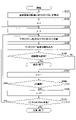
図8は、マクロフローの再生成処理の処理手順の一例を説明するためのフローチャートである。
ステップS101において、マクロフロー再生成部14は、経路割当結果に含まれるマクロフロー要求品質情報に係る全マクロフローを、各マクロフローの要求帯域の降順に整列する。
続いて、マクロフロー再生成部14は、変数iに1を代入する(S102)。変数iは、整列後において処理対象のマクロフローの順番が格納される変数である。以下、i番目のマクロフローを「マクロフローi」という。
続いて、マクロフロー再生成部14は、変数jに2を代入する(S103)。変数jは、マクロフローiの分割数が格納される変数である。すなわち、本実施の形態において、各マクロフローの分割数の初期値は2である。
続いて、マクロフロー再生成部14は、分割後の各マクロフローの要求帯域がなるべく均等になるようにマクロフローiをj本のマクロフローへ分割する(S104)。ここで、「分割後の各マクロフロー」とは、マクロフローiを構成するミクロフロー群の分割によって新たに生成される各マクロフローをいう。この際、上述したように、分割の最小単位はマクロフローiを構成するミクロフローである。したがって、分割後の各マクロフローの要求帯域が完全に一致しない場合もある。したがって、マクロフロー再生成部14は、例えば、分割後の各マクロフローの要求帯域の差の総和が最小となるようにマクロフローiをj本のマクロフローへ分割する。
続いて、マクロフロー再生成部14は、分割後のマクロフローごとに当該マクロフローを構成する各ミクロフローの要求品質を含み、分割されていないマクロフローごとに当該マクロフローを構成する各ミクロフローの要求品質を含むマクロフロー構成情報をマクロフロー要求品質計算部13へ出力する(S105)。
その後、マクロフロー要求品質計算部13によって、当該マクロフロー構成情報に基づいて各マクロフローの要求品質が計算され、計算結果であるマクロフロー要求品質情報が経路計算装置30へ送信される。経路計算装置30は、当該マクロフロー要求品質情報に基づいて、各マクロフローに割り当てる経路を計算し、経路割当結果をマクロフロー再生成部14へ送信する。
マクロフロー再生成部14は、当該経路割当結果を受信すると、当該経路割当結果の「結果」が経路割当の成功を示す値であるか否かを判定する(S106)。「結果」が経路割当の成功を示す値である場合(S106でYes)、マクロフロー再生成部14は処理を終了する。一方、「結果」が経路割当の失敗を示す値である場合(S106でNo)、マクロフロー再生成部14は、jに1を加算し(S107)、jの値が予め設定された閾値以下であるか否かを判定する(S108)。なお、マクロフローの分割数に閾値(上限)が設けられるのは、分割したマクロフロー数が大きすぎると、経路制御等をマクロフロー単位として扱う意義が薄れてしまうためである。
jの値が閾値以下である場合(S108でYes)、マクロフロー再生成部14は、ステップS104以降を繰り返す。jの値が閾値を超える場合(S108でNo)、マクロフロー再生成部14は、iに1を加算する(S109)。続いて、マクロフロー再生成部14は、iの値が経路割当結果のマクロフロー要求品質情報に係るマクロフローの本数以下であるか否かを判定する(S110)。iの値が当該本数以下である場合(S110でYes)、マクロフロー再生成部14は、ステップS103以降を繰り返す。なお、ステップS103以降は、当初の(ステップS101の時点の)各マクロフローに対して実行される。すなわち、当初のいずれかのマクロフローの分割によって生成されたマクロフローはステップS103の処理の対象外である。
iの値が当該本数を超えた場合(S110でNo)、マクロフロー再生成部14は、処理を終了する。この場合(すなわち、当初の全てのマクロフローが上限まで分割された場合)、現在のミクロフローの品質要件では、どのようにマクロフローを再生成(再構成)しても経路割当が成功しないため、マクロフロー再生成部14は、端末制御装置40を介して品質要件変更を各ユーザ端末60のアプリケーションへ送信する。
品質要件変更は、ユーザ端末60の品質要件をどのように変更するかの指示を示す情報である。品質要件の変更については、様々なものが考えられるが、図7では、目標QoE値が5に設定されているミクロフローの目標QoE値を4に下げるように、相対的に高い品質を要求しているサービスのトラヒックを優先的に順次低減する方法が例示されている。また、ユーザの契約プランにより、帯域確保型プランを契約しているユーザの契約帯域以下になるようには目標QoEは下げず、ベストエフォート型プランを契約しているユーザの目標QoEを優先的に下げる、といった手法に基づいて品質要件変更が生成されてもよい。
上述したように、本実施の形態によれば、ユーザ端末60にインストールされているサービス事業者によって提供されるアプリケーションからフィードバックされるミクロフローの品質要件を用いるため、通信品質の低下を招く経路割当が実施される可能性を低下させるマクロフローを生成することができる。また、経路割当に失敗した場合でも、マクロフローが再構成されるため、通信品質の低下を更に抑制ことができる。その結果、ユーザの体感品質の向上を期待することができる。
また、本実施の形態では、マクロフローの再構成を行っても経路割当に失敗する場合には、複数のミクロフローの一部又は全部のそれぞれの品質要件を低下させるための制御が行われる。その点においても、通信品質の低下を招く経路割当が実施される可能性を低下させるマクロフローを生成することができる。
以上、本発明の実施の形態について詳述したが、本発明は斯かる特定の実施形態に限定されるものではなく、請求の範囲に記載された本発明の要旨の範囲内において、種々の変形・変更が可能である。
10 マクロフロー生成装置
11 ミクロフロー要求品質計算部
12 マクロフロー生成部
13 マクロフロー要求品質計算部
14 マクロフロー再生成部
20 端末情報収集装置
30 経路計算装置
40 端末制御装置
50 ネットワーク制御装置50
60 ユーザ端末
70 サーバ
100 ドライブ装置
101 記録媒体
102 補助記憶装置
103 メモリ装置
104 CPU
105 インタフェース装置
B バス
N1 通信ネットワーク
T1 変換テーブル
11 ミクロフロー要求品質計算部
12 マクロフロー生成部
13 マクロフロー要求品質計算部
14 マクロフロー再生成部
20 端末情報収集装置
30 経路計算装置
40 端末制御装置
50 ネットワーク制御装置50
60 ユーザ端末
70 サーバ
100 ドライブ装置
101 記録媒体
102 補助記憶装置
103 メモリ装置
104 CPU
105 インタフェース装置
B バス
N1 通信ネットワーク
T1 変換テーブル
Claims (7)
- ネットワークを介して提供されるサービスを利用する複数の端末のそれぞれの個別のフローについて前記各端末から収集される、複数の前記個別のフローの要求品質の類似性に基づいて、前記複数の個別のフローの集合を、それぞれが1以上の前記フローを含むマクロフローに分割するマクロフロー生成部と、
前記マクロフローごとに、当該マクロフローに属する1以上の前記個別のフローの要求品質に基づいて当該マクロフローの要求品質を計算するマクロフロー要求品質計算部と、
を有することを特徴とするマクロフロー生成装置。 - 前記マクロフローごとの要求品質に基づく前記マクロフロー単位での経路割当に失敗した場合に、一部又は全部の前記マクロフローを分割して、前記マクロフローを再生成するマクロフロー再生成部、
を有することを特徴とする請求項1記載のマクロフロー生成装置。 - 前記マクロフロー再生成部は、再生成した前記各マクロフローについて前記マクロフロー要求品質計算部が計算した当該各マクロフローの要求品質に基づく前記経路割当に失敗した場合に、前記複数の個別のフローのうちの一部又は全部のフローの要求品質を変更させるための制御を行う、
ことを特徴とする請求項2記載のマクロフロー生成装置。 - 前記マクロフロー再生成部は、相対的に求品質が高いマクロフローを優先的に分割する、
ことを特徴とする請求項2又は3記載のマクロフロー生成装置。 - 前記マクロフロー生成部は、前記マクロフローごとに当該マクロフローに属する前記個別のフローの要求品質を含むマクロフロー構成情報を生成し、
前記マクロフロー要求品質計算部は、前記マクロフロー構成情報に対して、前記マクロフローの要求品質が追加されたマクロフロー要求品質情報を生成する、
ことを特徴とする請求項1乃至4いずれか一項記載のマクロフロー生成装置。 - ネットワークを介して提供されるサービスを利用する複数の端末のそれぞれの個別のフローについて前記各端末から収集される、複数の前記個別のフローの要求品質の類似性に基づいて、前記複数の個別のフローの集合を、それぞれが1以上の前記フローを含むマクロフローに分割するマクロフロー生成手順と、
前記マクロフローごとに、当該マクロフローに属する1以上の前記個別のフローの要求品質に基づいて当該マクロフローの要求品質を計算するマクロフロー要求品質計算手順と、
をコンピュータが実行することを特徴とするマクロフロー生成方法。 - 請求項1乃至5いずれか一項記載のマクロフロー生成装置としてコンピュータを機能させることを特徴とするプログラム。
Priority Applications (3)
| Application Number | Priority Date | Filing Date | Title |
|---|---|---|---|
| US18/250,046 US20230396537A1 (en) | 2020-10-26 | 2020-10-26 | Macro-flow generation apparatus, macro-flow generation method and program |
| JP2022558604A JP7473004B2 (ja) | 2020-10-26 | 2020-10-26 | マクロフロー生成装置、マクロフロー生成方法及びプログラム |
| PCT/JP2020/040060 WO2022091171A1 (ja) | 2020-10-26 | 2020-10-26 | マクロフロー生成装置、マクロフロー生成方法及びプログラム |
Applications Claiming Priority (1)
| Application Number | Priority Date | Filing Date | Title |
|---|---|---|---|
| PCT/JP2020/040060 WO2022091171A1 (ja) | 2020-10-26 | 2020-10-26 | マクロフロー生成装置、マクロフロー生成方法及びプログラム |
Publications (1)
| Publication Number | Publication Date |
|---|---|
| WO2022091171A1 true WO2022091171A1 (ja) | 2022-05-05 |
Family
ID=81383731
Family Applications (1)
| Application Number | Title | Priority Date | Filing Date |
|---|---|---|---|
| PCT/JP2020/040060 Ceased WO2022091171A1 (ja) | 2020-10-26 | 2020-10-26 | マクロフロー生成装置、マクロフロー生成方法及びプログラム |
Country Status (3)
| Country | Link |
|---|---|
| US (1) | US20230396537A1 (ja) |
| JP (1) | JP7473004B2 (ja) |
| WO (1) | WO2022091171A1 (ja) |
Families Citing this family (1)
| Publication number | Priority date | Publication date | Assignee | Title |
|---|---|---|---|---|
| CN112767956B (zh) * | 2021-04-09 | 2021-07-16 | 腾讯科技(深圳)有限公司 | 音频编码方法、装置、计算机设备及介质 |
Citations (2)
| Publication number | Priority date | Publication date | Assignee | Title |
|---|---|---|---|---|
| JP2015156529A (ja) * | 2014-02-19 | 2015-08-27 | 日本電信電話株式会社 | フロー集約装置及び方法及びプログラム |
| WO2017082185A1 (ja) * | 2015-11-13 | 2017-05-18 | 日本電信電話株式会社 | リソース割当装置及びリソース割当方法 |
-
2020
- 2020-10-26 US US18/250,046 patent/US20230396537A1/en active Pending
- 2020-10-26 WO PCT/JP2020/040060 patent/WO2022091171A1/ja not_active Ceased
- 2020-10-26 JP JP2022558604A patent/JP7473004B2/ja active Active
Patent Citations (2)
| Publication number | Priority date | Publication date | Assignee | Title |
|---|---|---|---|---|
| JP2015156529A (ja) * | 2014-02-19 | 2015-08-27 | 日本電信電話株式会社 | フロー集約装置及び方法及びプログラム |
| WO2017082185A1 (ja) * | 2015-11-13 | 2017-05-18 | 日本電信電話株式会社 | リソース割当装置及びリソース割当方法 |
Also Published As
| Publication number | Publication date |
|---|---|
| JP7473004B2 (ja) | 2024-04-23 |
| JPWO2022091171A1 (ja) | 2022-05-05 |
| US20230396537A1 (en) | 2023-12-07 |
Similar Documents
| Publication | Publication Date | Title |
|---|---|---|
| CN109995583B (zh) | 一种延迟保证的nfv云平台动态扩缩容方法及系统 | |
| CN108599994B (zh) | 一种基于流量聚类的sdn切片构造方法 | |
| CN111404833B (zh) | 一种数据流类型识别模型更新方法及相关设备 | |
| JP2022548136A (ja) | データストリーム分類方法および関連デバイス | |
| CN116389365A (zh) | 一种交换机数据处理方法及系统 | |
| Quinlan et al. | Delivery of adaptive bit rate video: balancing fairness, efficiency and quality | |
| CN114938374A (zh) | 跨协议负载均衡方法及系统 | |
| CN116074204A (zh) | 算路方法、路由计算设备、电子设备和计算机存储介质 | |
| Parameshachari et al. | RETRACTED ARTICLE: Cognitive linear discriminant regression computing technique for HTTP video services in SDN networks | |
| JP6660283B2 (ja) | トラヒック需要予測装置、トラヒック需要予測方法、及びプログラム | |
| CN103888849A (zh) | 移动云视频传输中的计算和无线资源协同调度方法 | |
| Huang et al. | Digital twin-assisted collaborative transcoding for better user satisfaction in live streaming | |
| JP7473004B2 (ja) | マクロフロー生成装置、マクロフロー生成方法及びプログラム | |
| US20150372895A1 (en) | Proactive Change of Communication Models | |
| CN112106335B (zh) | 用于经由内容分发网络流式传输媒体数据的方法及系统 | |
| CN117336291B (zh) | 网络资源服务处理方法、电子设备和存储介质 | |
| US12476923B2 (en) | Providing estimated bandwidth ranges to network-attached entities | |
| JP7424465B2 (ja) | 制御装置、制御方法及びプログラム | |
| WO2024146193A1 (zh) | 一种基于sdn的路由路径选择方法、装置及存储介质 | |
| Liu et al. | Dynamic routing with online traffic estimation for video streaming over software defined networks | |
| Das et al. | Smartly managing traffic and latency in a content-based data center using modified packet headers, machine learning, load balancing, and network telemetry | |
| Kharga et al. | Enhancing Immersive Streaming CDN through MEC-EdgeAI in NG-EPON & 6G-Xhaul Access Network | |
| Kostiv et al. | Metaheuristics in cloud platform traffic engineering | |
| Hayes et al. | Lightweight evolving 360 VR adaptive video delivery | |
| CN119629062B (zh) | 数据处理方法、装置及云服务系统 |
Legal Events
| Date | Code | Title | Description |
|---|---|---|---|
| ENP | Entry into the national phase |
Ref document number: 2022558604 Country of ref document: JP Kind code of ref document: A |
|
| NENP | Non-entry into the national phase |
Ref country code: DE |
|
| 122 | Ep: pct application non-entry in european phase |
Ref document number: 20959689 Country of ref document: EP Kind code of ref document: A1 |