WO2022089930A2 - Compact system and method for the production of liquefied natural gas - Google Patents
Compact system and method for the production of liquefied natural gas Download PDFInfo
- Publication number
- WO2022089930A2 WO2022089930A2 PCT/EP2021/078096 EP2021078096W WO2022089930A2 WO 2022089930 A2 WO2022089930 A2 WO 2022089930A2 EP 2021078096 W EP2021078096 W EP 2021078096W WO 2022089930 A2 WO2022089930 A2 WO 2022089930A2
- Authority
- WO
- WIPO (PCT)
- Prior art keywords
- module
- liquefaction
- facility
- mixed refrigerant
- cooling
- Prior art date
- Legal status (The legal status is an assumption and is not a legal conclusion. Google has not performed a legal analysis and makes no representation as to the accuracy of the status listed.)
- Ceased
Links
Classifications
-
- F—MECHANICAL ENGINEERING; LIGHTING; HEATING; WEAPONS; BLASTING
- F25—REFRIGERATION OR COOLING; COMBINED HEATING AND REFRIGERATION SYSTEMS; HEAT PUMP SYSTEMS; MANUFACTURE OR STORAGE OF ICE; LIQUEFACTION SOLIDIFICATION OF GASES
- F25J—LIQUEFACTION, SOLIDIFICATION OR SEPARATION OF GASES OR GASEOUS OR LIQUEFIED GASEOUS MIXTURES BY PRESSURE AND COLD TREATMENT OR BY BRINGING THEM INTO THE SUPERCRITICAL STATE
- F25J1/00—Processes or apparatus for liquefying or solidifying gases or gaseous mixtures
- F25J1/0002—Processes or apparatus for liquefying or solidifying gases or gaseous mixtures characterised by the fluid to be liquefied
- F25J1/0022—Hydrocarbons, e.g. natural gas
-
- F—MECHANICAL ENGINEERING; LIGHTING; HEATING; WEAPONS; BLASTING
- F25—REFRIGERATION OR COOLING; COMBINED HEATING AND REFRIGERATION SYSTEMS; HEAT PUMP SYSTEMS; MANUFACTURE OR STORAGE OF ICE; LIQUEFACTION SOLIDIFICATION OF GASES
- F25J—LIQUEFACTION, SOLIDIFICATION OR SEPARATION OF GASES OR GASEOUS OR LIQUEFIED GASEOUS MIXTURES BY PRESSURE AND COLD TREATMENT OR BY BRINGING THEM INTO THE SUPERCRITICAL STATE
- F25J1/00—Processes or apparatus for liquefying or solidifying gases or gaseous mixtures
- F25J1/003—Processes or apparatus for liquefying or solidifying gases or gaseous mixtures characterised by the kind of cold generation within the liquefaction unit for compensating heat leaks and liquid production
- F25J1/0047—Processes or apparatus for liquefying or solidifying gases or gaseous mixtures characterised by the kind of cold generation within the liquefaction unit for compensating heat leaks and liquid production using an "external" refrigerant stream in a closed vapor compression cycle
- F25J1/0052—Processes or apparatus for liquefying or solidifying gases or gaseous mixtures characterised by the kind of cold generation within the liquefaction unit for compensating heat leaks and liquid production using an "external" refrigerant stream in a closed vapor compression cycle by vaporising a liquid refrigerant stream
- F25J1/0055—Processes or apparatus for liquefying or solidifying gases or gaseous mixtures characterised by the kind of cold generation within the liquefaction unit for compensating heat leaks and liquid production using an "external" refrigerant stream in a closed vapor compression cycle by vaporising a liquid refrigerant stream originating from an incorporated cascade
-
- F—MECHANICAL ENGINEERING; LIGHTING; HEATING; WEAPONS; BLASTING
- F25—REFRIGERATION OR COOLING; COMBINED HEATING AND REFRIGERATION SYSTEMS; HEAT PUMP SYSTEMS; MANUFACTURE OR STORAGE OF ICE; LIQUEFACTION SOLIDIFICATION OF GASES
- F25J—LIQUEFACTION, SOLIDIFICATION OR SEPARATION OF GASES OR GASEOUS OR LIQUEFIED GASEOUS MIXTURES BY PRESSURE AND COLD TREATMENT OR BY BRINGING THEM INTO THE SUPERCRITICAL STATE
- F25J1/00—Processes or apparatus for liquefying or solidifying gases or gaseous mixtures
- F25J1/02—Processes or apparatus for liquefying or solidifying gases or gaseous mixtures requiring the use of refrigeration, e.g. of helium or hydrogen ; Details and kind of the refrigeration system used; Integration with other units or processes; Controlling aspects of the process
- F25J1/0211—Processes or apparatus for liquefying or solidifying gases or gaseous mixtures requiring the use of refrigeration, e.g. of helium or hydrogen ; Details and kind of the refrigeration system used; Integration with other units or processes; Controlling aspects of the process using a multi-component refrigerant [MCR] fluid in a closed vapor compression cycle
- F25J1/0214—Processes or apparatus for liquefying or solidifying gases or gaseous mixtures requiring the use of refrigeration, e.g. of helium or hydrogen ; Details and kind of the refrigeration system used; Integration with other units or processes; Controlling aspects of the process using a multi-component refrigerant [MCR] fluid in a closed vapor compression cycle as a dual level refrigeration cascade with at least one MCR cycle
-
- F—MECHANICAL ENGINEERING; LIGHTING; HEATING; WEAPONS; BLASTING
- F25—REFRIGERATION OR COOLING; COMBINED HEATING AND REFRIGERATION SYSTEMS; HEAT PUMP SYSTEMS; MANUFACTURE OR STORAGE OF ICE; LIQUEFACTION SOLIDIFICATION OF GASES
- F25J—LIQUEFACTION, SOLIDIFICATION OR SEPARATION OF GASES OR GASEOUS OR LIQUEFIED GASEOUS MIXTURES BY PRESSURE AND COLD TREATMENT OR BY BRINGING THEM INTO THE SUPERCRITICAL STATE
- F25J1/00—Processes or apparatus for liquefying or solidifying gases or gaseous mixtures
- F25J1/02—Processes or apparatus for liquefying or solidifying gases or gaseous mixtures requiring the use of refrigeration, e.g. of helium or hydrogen ; Details and kind of the refrigeration system used; Integration with other units or processes; Controlling aspects of the process
- F25J1/0228—Coupling of the liquefaction unit to other units or processes, so-called integrated processes
- F25J1/0235—Heat exchange integration
- F25J1/0237—Heat exchange integration integrating refrigeration provided for liquefaction and purification/treatment of the gas to be liquefied, e.g. heavy hydrocarbon removal from natural gas
- F25J1/0238—Purification or treatment step is integrated within one refrigeration cycle only, i.e. the same or single refrigeration cycle provides feed gas cooling (if present) and overhead gas cooling
-
- F—MECHANICAL ENGINEERING; LIGHTING; HEATING; WEAPONS; BLASTING
- F25—REFRIGERATION OR COOLING; COMBINED HEATING AND REFRIGERATION SYSTEMS; HEAT PUMP SYSTEMS; MANUFACTURE OR STORAGE OF ICE; LIQUEFACTION SOLIDIFICATION OF GASES
- F25J—LIQUEFACTION, SOLIDIFICATION OR SEPARATION OF GASES OR GASEOUS OR LIQUEFIED GASEOUS MIXTURES BY PRESSURE AND COLD TREATMENT OR BY BRINGING THEM INTO THE SUPERCRITICAL STATE
- F25J1/00—Processes or apparatus for liquefying or solidifying gases or gaseous mixtures
- F25J1/02—Processes or apparatus for liquefying or solidifying gases or gaseous mixtures requiring the use of refrigeration, e.g. of helium or hydrogen ; Details and kind of the refrigeration system used; Integration with other units or processes; Controlling aspects of the process
- F25J1/0228—Coupling of the liquefaction unit to other units or processes, so-called integrated processes
- F25J1/0235—Heat exchange integration
- F25J1/0237—Heat exchange integration integrating refrigeration provided for liquefaction and purification/treatment of the gas to be liquefied, e.g. heavy hydrocarbon removal from natural gas
- F25J1/0239—Purification or treatment step being integrated between two refrigeration cycles of a refrigeration cascade, i.e. first cycle providing feed gas cooling and second cycle providing overhead gas cooling
-
- F—MECHANICAL ENGINEERING; LIGHTING; HEATING; WEAPONS; BLASTING
- F25—REFRIGERATION OR COOLING; COMBINED HEATING AND REFRIGERATION SYSTEMS; HEAT PUMP SYSTEMS; MANUFACTURE OR STORAGE OF ICE; LIQUEFACTION SOLIDIFICATION OF GASES
- F25J—LIQUEFACTION, SOLIDIFICATION OR SEPARATION OF GASES OR GASEOUS OR LIQUEFIED GASEOUS MIXTURES BY PRESSURE AND COLD TREATMENT OR BY BRINGING THEM INTO THE SUPERCRITICAL STATE
- F25J1/00—Processes or apparatus for liquefying or solidifying gases or gaseous mixtures
- F25J1/02—Processes or apparatus for liquefying or solidifying gases or gaseous mixtures requiring the use of refrigeration, e.g. of helium or hydrogen ; Details and kind of the refrigeration system used; Integration with other units or processes; Controlling aspects of the process
- F25J1/0243—Start-up or control of the process; Details of the apparatus used; Details of the refrigerant compression system used
- F25J1/0257—Construction and layout of liquefaction equipments, e.g. valves, machines
- F25J1/0259—Modularity and arrangement of parts of the liquefaction unit and in particular of the cold box, e.g. pre-fabrication, assembling and erection, dimensions, horizontal layout "plot"
-
- F—MECHANICAL ENGINEERING; LIGHTING; HEATING; WEAPONS; BLASTING
- F25—REFRIGERATION OR COOLING; COMBINED HEATING AND REFRIGERATION SYSTEMS; HEAT PUMP SYSTEMS; MANUFACTURE OR STORAGE OF ICE; LIQUEFACTION SOLIDIFICATION OF GASES
- F25J—LIQUEFACTION, SOLIDIFICATION OR SEPARATION OF GASES OR GASEOUS OR LIQUEFIED GASEOUS MIXTURES BY PRESSURE AND COLD TREATMENT OR BY BRINGING THEM INTO THE SUPERCRITICAL STATE
- F25J1/00—Processes or apparatus for liquefying or solidifying gases or gaseous mixtures
- F25J1/02—Processes or apparatus for liquefying or solidifying gases or gaseous mixtures requiring the use of refrigeration, e.g. of helium or hydrogen ; Details and kind of the refrigeration system used; Integration with other units or processes; Controlling aspects of the process
- F25J1/0243—Start-up or control of the process; Details of the apparatus used; Details of the refrigerant compression system used
- F25J1/0257—Construction and layout of liquefaction equipments, e.g. valves, machines
- F25J1/0269—Arrangement of liquefaction units or equipments fulfilling the same process step, e.g. multiple "trains" concept
- F25J1/027—Inter-connecting multiple hot equipments upstream of the cold box
-
- F—MECHANICAL ENGINEERING; LIGHTING; HEATING; WEAPONS; BLASTING
- F25—REFRIGERATION OR COOLING; COMBINED HEATING AND REFRIGERATION SYSTEMS; HEAT PUMP SYSTEMS; MANUFACTURE OR STORAGE OF ICE; LIQUEFACTION SOLIDIFICATION OF GASES
- F25J—LIQUEFACTION, SOLIDIFICATION OR SEPARATION OF GASES OR GASEOUS OR LIQUEFIED GASEOUS MIXTURES BY PRESSURE AND COLD TREATMENT OR BY BRINGING THEM INTO THE SUPERCRITICAL STATE
- F25J1/00—Processes or apparatus for liquefying or solidifying gases or gaseous mixtures
- F25J1/02—Processes or apparatus for liquefying or solidifying gases or gaseous mixtures requiring the use of refrigeration, e.g. of helium or hydrogen ; Details and kind of the refrigeration system used; Integration with other units or processes; Controlling aspects of the process
- F25J1/0243—Start-up or control of the process; Details of the apparatus used; Details of the refrigerant compression system used
- F25J1/0279—Compression of refrigerant or internal recycle fluid, e.g. kind of compressor, accumulator, suction drum etc.
- F25J1/0292—Refrigerant compression by cold or cryogenic suction of the refrigerant gas
-
- F—MECHANICAL ENGINEERING; LIGHTING; HEATING; WEAPONS; BLASTING
- F25—REFRIGERATION OR COOLING; COMBINED HEATING AND REFRIGERATION SYSTEMS; HEAT PUMP SYSTEMS; MANUFACTURE OR STORAGE OF ICE; LIQUEFACTION SOLIDIFICATION OF GASES
- F25J—LIQUEFACTION, SOLIDIFICATION OR SEPARATION OF GASES OR GASEOUS OR LIQUEFIED GASEOUS MIXTURES BY PRESSURE AND COLD TREATMENT OR BY BRINGING THEM INTO THE SUPERCRITICAL STATE
- F25J1/00—Processes or apparatus for liquefying or solidifying gases or gaseous mixtures
- F25J1/02—Processes or apparatus for liquefying or solidifying gases or gaseous mixtures requiring the use of refrigeration, e.g. of helium or hydrogen ; Details and kind of the refrigeration system used; Integration with other units or processes; Controlling aspects of the process
- F25J1/0243—Start-up or control of the process; Details of the apparatus used; Details of the refrigerant compression system used
- F25J1/0279—Compression of refrigerant or internal recycle fluid, e.g. kind of compressor, accumulator, suction drum etc.
- F25J1/0296—Removal of the heat of compression, e.g. within an inter- or afterstage-cooler against an ambient heat sink
-
- F—MECHANICAL ENGINEERING; LIGHTING; HEATING; WEAPONS; BLASTING
- F25—REFRIGERATION OR COOLING; COMBINED HEATING AND REFRIGERATION SYSTEMS; HEAT PUMP SYSTEMS; MANUFACTURE OR STORAGE OF ICE; LIQUEFACTION SOLIDIFICATION OF GASES
- F25J—LIQUEFACTION, SOLIDIFICATION OR SEPARATION OF GASES OR GASEOUS OR LIQUEFIED GASEOUS MIXTURES BY PRESSURE AND COLD TREATMENT OR BY BRINGING THEM INTO THE SUPERCRITICAL STATE
- F25J2220/00—Processes or apparatus involving steps for the removal of impurities
- F25J2220/60—Separating impurities from natural gas, e.g. mercury, cyclic hydrocarbons
- F25J2220/64—Separating heavy hydrocarbons, e.g. NGL, LPG, C4+ hydrocarbons or heavy condensates in general
-
- F—MECHANICAL ENGINEERING; LIGHTING; HEATING; WEAPONS; BLASTING
- F25—REFRIGERATION OR COOLING; COMBINED HEATING AND REFRIGERATION SYSTEMS; HEAT PUMP SYSTEMS; MANUFACTURE OR STORAGE OF ICE; LIQUEFACTION SOLIDIFICATION OF GASES
- F25J—LIQUEFACTION, SOLIDIFICATION OR SEPARATION OF GASES OR GASEOUS OR LIQUEFIED GASEOUS MIXTURES BY PRESSURE AND COLD TREATMENT OR BY BRINGING THEM INTO THE SUPERCRITICAL STATE
- F25J2220/00—Processes or apparatus involving steps for the removal of impurities
- F25J2220/60—Separating impurities from natural gas, e.g. mercury, cyclic hydrocarbons
- F25J2220/66—Separating acid gases, e.g. CO2, SO2, H2S or RSH
-
- F—MECHANICAL ENGINEERING; LIGHTING; HEATING; WEAPONS; BLASTING
- F25—REFRIGERATION OR COOLING; COMBINED HEATING AND REFRIGERATION SYSTEMS; HEAT PUMP SYSTEMS; MANUFACTURE OR STORAGE OF ICE; LIQUEFACTION SOLIDIFICATION OF GASES
- F25J—LIQUEFACTION, SOLIDIFICATION OR SEPARATION OF GASES OR GASEOUS OR LIQUEFIED GASEOUS MIXTURES BY PRESSURE AND COLD TREATMENT OR BY BRINGING THEM INTO THE SUPERCRITICAL STATE
- F25J2290/00—Other details not covered by groups F25J2200/00 - F25J2280/00
- F25J2290/10—Mathematical formulae, modeling, plot or curves; Design methods
Definitions
- the present invention is directed to a system and a method for the production of liquefied natural gas (LNG).
- LNG liquefied natural gas
- Natural gas is routinely transported from one location to another location in its liquid state as Liquefied Natural Gas (LNG). Liquefaction of the natural gas makes it more economical to transport as LNG occupies only about 1/600 of the volume that the same amount of natural gas does in its gaseous state.
- LNG is typically stored in cryogenic containers, typically either at or slightly above atmospheric pressure. LNG can be regasified before distribution to end users through a pipeline or other distribution network at a temperature and pressure that meets the delivery requirements of the end users.
- Liquefaction is achieved using processes which typically involve compression, expansion and cooling. Such processes are applied in technologies such as C3/MR process, the AP-XTM process, the Cascade Process, the Mixed Fluid Cascade process or the Double Mixed Refrigerant or Parallel Mixed Refrigerant process.
- US-2014/053599-A1 discloses a liquefied natural gas production facility comprising a plurality of spaced-apart modules for installation at a production location to form a production train having a major axis and a minor axis, each module having a module base for mounting a plurality of plant equipment associated with a selected function assigned to said module, the module base having a major axis and a minor axis; and a plurality of heat exchangers arranged to run parallel to the major axis of the production train to form a heat exchanger bank having a major axis and a minor axis
- US-2016/0010916-A1 discloses a liquefied natural gas production process for producing a product stream of liquefied natural gas at a production location, said process comprising: a) designing a plurality of modules for installation at the production location to form an installed production train; (b) designing an air-cooled heat exchanger bank including: a first row of air-cooled heat exchanger bays, and, an adjacent parallel second row of air-cooled heat exchanger bays; (c) arranging a first sub-section of the first row of heat exchanger bays at an elevated level vertically offset from and towards a first edge of a first module base to form a covered section of the first module base, the first module base being designed and sized to include an uncovered section for mounting a selected piece of process equipment, wherein the first module includes the first subsection of the first row of heat exchanger bays without including a sub-section of the second row of heat exchanger bays; (d) arranging a first sub-section of the second row of heat exchanger bays at an elevated level
- WO2019110769 in the name of applicant provides a modular liquefaction train for LNG production, with reduced capital expenditure and footprint.
- Footprint herein refers to the area of the liquefaction train. Area herein refers to the surface included within the boundaries of the liquefaction train.
- a facility for the production of liquefied natural comprises an inside battery limit (ISBL) comprising a liquefaction train.
- the liquefaction train comprises a plurality of modules with each module being adapted to perform at least one process step associated with liquefied natural gas production.
- the plurality of modules comprise a first module for acid gas removal; a second module comprising a dehydration unit; a third module, being the liquefaction module; and a fourth module comprising equipment for processing of natural gas liquids.
- the train further comprises a first mixed refrigerant cycle comprising a first mixed refrigerant and a second mixed refrigerant cycle comprising a second mixed refrigerant connected to the liquefaction module for cooling a gas stream to produce the liquefied natural gas.
- the train further comprises a primary cooling loop to cool at least a process stream from each module and the first mixed refrigerant and the second mixed refrigerant against a first coolant comprising clean water.
- the primary cooling loop is a closed clean water cooling loop and the cooling is against an ambient temperature.
- the train further comprises a first plurality of heat exchangers through which the primary cooling loop extends, and the cooling by the primary cooling loop is via heat exchange in at least the first plurality of heat exchangers with respect to the first coolant. More than 50% of the first plurality of heat exchangers are printed circuit heat exchangers which are adapted to provide at least 80% of the cooling against the ambient temperature.
- the liquefaction train further comprises a second plurality of heat exchangers through which the primary cooling loop extends to cool the first coolant by heat exchange with a second coolant
- the facility further comprises
- the second coolant comprises water from a cooling tower system, sea water, or air.
- the first module having a first side engaging a first side of the second module
- the second module having a second side opposite the first side engaging a first side of the fourth module.
- the liquefaction train further comprises a first module series comprising the first module engaging the second module engaging the fourth module, the first module series being aligned with and arranged adjacent to a second module series comprising the third module arranged between the first compressor on one side and the second compressor on the opposite side.
- the liquefaction train further comprises:
- a second compressor arranged on a second side of the liquefaction module, the second side being opposite to the first side, and connected to the second mixed refrigerant cycle for compressing the second mixed refrigerant.
- the liquefaction train further comprises:
- a main heat exchanger arranged on the second side of the third module, the second side being opposite to the first side, and connected to the second mixed refrigerant cycle for at least partially liquefying the pre-cooled gas stream in heat exchange with respect to the second mixed refrigerant.
- the liquefaction train further comprises a pipe-rack for supporting conduits, the pipe-rack extending through at least the first module, the second module and the fourth module.
- the first mixed refrigerant cycle comprises a single precool heat exchanger.
- the first mixed refrigerant cycle can further comprise a compressor intercooler adapted to cool first mixed refrigerant compressed by the first compressor without condensing the first mixed refrigerant, an outlet of the compressor intercooler being connected to a subsequent stage of the first compressor.
- the liquefaction train has a capacity of production of liquefied natural gas in the range of about 2 to 4 MTPA.
- Figure 1 shows a diagram of a liquefaction system suitable for a system of the disclosure
- Figure 2A shows a diagram of another embodiment of a liquefaction system suitable for a system of the present disclosure
- Figure 2B shows a diagram of yet another embodiment of a liquefaction system suitable for a system of the present disclosure
- Figure 5A shows a plan view of another embodiment of a system according to the disclosure.
- Figure 5B shows a plan view of an embodiment of the system of the disclosure, including a diagrammatical example of a flow of feed gas from gaseous feed to liquefied product;
- Figure 5C shows a plan view of an embodiment of the system of the disclosure, including a diagrammatical example of a flow of cooling water through the modules;
- Figure 6 shows a diagram indicating dependence of total equipment weight (in tonnes) for a liquefaction system of a selected total capacity on size of each liquefaction train (in million tonne per annum [mtpa]);
- Figure 7 schematically shows a perspective view of a shell-and-tube heat exchanger and a printed circuit heat exchanger for use in a system of the present disclosure
- Figure 8 shows a diagram indicating rationale of designing a system of the present disclosure
- Figure 9 shows a diagram indicating a relation between a ratio of module weight to equipment weight (vertical axis) and (mechanical) equipment weight (in tonnes) for modules of embodiments of the disclosures and modules of conventional projects as reference;
- Figure 10 shows a diagram indicating an exemplary relation between fabrication time (in months) and module weight (in tonnes);
- Figure 11 shows a diagram of an exemplary cooling water loop for a system of the present disclosure
- Figures 12A, 12B and 12C respectively show, on the same scale and for the same liquefaction capacity (in mtpa), schematic representations in plan view of an exemplary conventional stick-built liquefaction train, an exemplary state of the art modular liquefaction train, and an embodiment of a liquefaction system according to the present disclosure;
- Figure 13 shows a plan view of an exemplary site layout of a facility for the production of liquefied natural gas, comprising a number of liquefaction trains, including state-of-the-art modular liquefaction trains and liquefaction systems according to the present disclosure.
- Figure 14 shows a plan view of a comparison of a footprint of an embodiment of a liquefaction system according to the present disclosure and a state-of-the-art modular built liquefaction facility, for the same production capacity (typically expressed in mtpa);
- Figure 15 shows a diagram indicating an area or plot space per unit of production (in mtpa) of a number of conventional (stick built and modular built) liquefaction facilities and of embodiments of a system according to the disclosure
- Figure 16 shows a diagram indicating green-house gas (GHG) intensity of a number of conventional liquefaction facilities (stick built and modular built) and of embodiments of a system according to the disclosure;
- GFG green-house gas
- Figure 17 shows a diagram indicating an estimate of pieces of equipment per unit of production (in mtpa) of a number of conventional liquefaction facilities and of embodiments of a system according to the disclosure.
- Figure 18 shows a diagram indicating module weight per unit of production (in mtpa) of a number of conventional modular built liquefaction facilities and of embodiments of a system according to the disclosure.
- LNG refers to liquefied natural gas
- NGLs Natural Gas Liquids
- hydrocarbon components of natural gas that are separated from the gas state in the form of liquids.
- NGLs may also be referred to as condensate.
- LPG relates to Liquid Petroleum Gases.
- LPG is a subset of NGL.
- LPG are C3 to C4s with high vapor pressure.
- LPG typically includes propane and butane. Trace amounts of C5 can be found in LPG due to the fractionation process.
- Heavy Hydrocarbons or “HHC” are hydrocarbon components comprising five carbon atoms or more (C5+ components), including aromatics.
- plant may refer to the LNG production plant including one or more LNG production trains.
- facility may refer to an LNG production plant, but may alternatively refer to an assembly in general.
- stick-built refers to an LNG production train which has sections built in subsequent order at the production location.
- stick-built is similar to conventional construction. Both refer to construction of a production train or another section of a plant predominantly at a production location.
- production location is the location of the plant itself.
- module refers to a section of a plant that may be preassembled at a construction or assembly location remote from the production location. Each module is typically designed to be transported from the construction or assembly location to the production location. Modules may be transported by towing or on floating barges, or by land using, for instance, rail or truck. After each module is moved from the construction or assembly location to the production location, the module is positioned in a suitable pre-determined orientation to suit the needs of a given LNG production facility.
- ISBL has its ordinary meaning known by one of ordinary skill in the art, including being defined as comprising all equipment and associated components (piping, etc.) that act upon the primary feed stream of a process, which is the process for the production of the liquefied natural gas in this instance (including removing contaminants from a natural gas feed stream to provide treated gas and cooling the treated gas to form liquefied natural gas).
- ISBL is functionalbased and refers to equipment and other components that are solely dedicated to a particular process (e.g., process for the production of the liquefied natural gas). Such equipment may be referred to as the ISBL equipment or ISBL units.
- OSBL Outside Battery Limits
- OSBL refers to systems (equipment pieces and associated components) that support several units, including ISBL units.
- Typical OSBL equipment includes cooling towers, water treatment facilities, tanks farms, LNG loading equipment, etc.
- Methodric Tons or "Tonnes” is a unit of weight equal to 1,000 kilograms.
- LNG plant capacity is usually specified in million metric tonnes per year (mt/y or mtpa).
- Module weight of respective modules is relevant to capital expenditure due to transportation costs, and the costs of steel to construct the respective modules.
- Module weight is an indicator for estimating costs.
- Module weight is typically linked to the number of fabrication hours in the yard as well as site hours and civil scope to support the modules on site.
- a foil process unit in a module 6.
- a first step involves a selection of a liquefaction process.
- Various liquefaction processes are available. A comparison is for instance provided in the article "Analysis of Process Efficiency for Baseload LNG Production” by T. J. Edwards et al. [1984] of Air Products and Chemicals Inc.
- the C3MR and DMR have similar thermodynamic efficiencies. Both are more efficient than the cascade liquefaction process.
- C3MR "has distinct advantages over the other process cycles, e.g. by way of simpler control, less costly and more reliable equipment, and ease of startup.” Consequently, the most commonly used liquefaction process for existing plants is the C3MR process.
- Relatively small LNG plants can use SMR (a process using a single mixed refrigerant cycle) or a nitrogen (N2) cooling cycle as liquefaction technology, but these technologies provide relatively poor liquefaction efficiency and increased specific green-house gas (GHG) emissions.
- SMR a process using a single mixed refrigerant cycle
- N2 nitrogen
- GHG green-house gas
- the DMR process provides certain benefits in combination with the modular setup. For instance, the Dual Mixed Refrigerant (DMR) process has a lower equipment count than C3MR and optimized cascade. Also, DMR enables to use lighter equipment.
- DMR Dual Mixed Refrigerant
- the pre-cool cycle of the DMR process can be based on single stage (single heat exchanger) or dual stage (two heat exchangers), as explained below.
- Figures 1 and 2 show embodiments of a liquefaction process suitable for the system of the disclosure.
- FIG. 1 shows a DMR process with a dual stage precool loop.
- Dual stage herein refers to two or more separate heat exchangers in the precool cycle, each consecutive heat exchanger operating at a lower internal pressure than the previous heat exchanger.
- Fig. 1 schematically depicts a system 1 and associated method for liquefying a gas 2, such as natural gas.
- a gas 2 such as natural gas.
- the gas 2 in its associated conduit may have been pre-treated.
- Several types of gas treatment can precede the scheme of Fig. 1.
- Various other types of equipment can be added downstream of the system to further process the at least partly condensed or fully liquefied gas 30 provided by the system of Fig. 1.
- Such equipment may include a nitrogen removal section or addition of an end-flash section. Also, there may be differences between respective liquefaction systems, for instance with respect to thermodynamics, pressure ranges, temperature ranges, and flow rates at various locations in the system during operation, equipment sizes, maximum capacity, etc.
- the liquefaction system 1 comprises two consecutive cooling cycles 4 and 6.
- the pre-cool cycle 4 may comprise at least one, for instance two heat exchangers 10 and 12 and at least one pre-cool refrigerant compressor 14.
- the cycle 4 may also include at least one cooler 15.
- Pre-cool refrigerant conduits 16 guide precool refrigerant from the compressor 14 through the two heat exchangers 10 and 12 and back.
- Refrigerant conduits 16 may comprise conduits 16a to 16f. Together, conduits 16 constitute a loop to circulate a refrigerant.
- the refrigerant circulated in loop 4 may be referred to as, for instance, precool refrigerant, precool mixed refrigerant (PMR) or first refrigerant.
- PMR precool mixed refrigerant
- the first pre-cool heat exchanger 10 may operate at a first pressure and the second pre-cool heat exchanger 12 may operate at a second pressure.
- the first pressure typically exceeds the second pressure.
- the first heat exchanger 10 may be referred to as high-pressure (HP) pre-cool heat exchanger.
- the second heat exchanger 12 may be referred to as low-pressure (LP) pre-cool heat exchanger.
- the main cooling cycle 6 comprises at least one main heat exchanger 20 and at least one main refrigerant compressor 22.
- the cycle 6 may include one of more coolers 23, 25.
- Main refrigerant conduits 24 extend from the compressor 22 through the two heat exchangers 10 and 12, subsequently through the at least one main heat exchanger 20, and back to the compressor 22.
- the cycle 6 may comprise a separator 26 to split the mixed refrigerant of the main cycle 6 in a heavy mixed refrigerant 27 and a light mixed refrigerant 28.
- Refrigerant conduits 24 may comprise conduits 24a to 24f. Together, conduits 24 constitute a loop to circulate a refrigerant.
- the refrigerant circulated in loop 6 via conduits 24 may be referred to as, for instance, main refrigerant, mixed refrigerant or second refrigerant.
- the gaseous feed stream 2 is routed via conduits extending through the two heat pre-cool exchangers 10 and 12, and subsequently through the at least one main heat exchanger 20, to provide at least partially condensed or liquefied gas 30.
- Both the pre-cooling cycle 4 and the main cooling cycle 6 may use a mixed or multi-component refrigerant to pre-cool and subsequently condense or liquefy the gaseous feed stream 2.
- Expanded pre-cool mixed refrigerant 50, 52 provides cooling duty to the pre-cool heat exchangers 10, 12 respectively and to all streams routed through the inside of said heat exchangers.
- Expanded heavy mixed refrigerant 29 and expanded light mixed refrigerant 31 provide cooling duty to the main cryogenic heat exchanger 20 and to all streams routed through the inside of the MCHE 20.
- the system 1 typically also includes a system 40 to remove natural gas liquids.
- a liquids removal section 40 comprising, for instance, a first separator 140, and a second separator 142.
- First and second separator 140, 142 may be flash vessels.
- the first separator may be a scrub column.
- a vertical scrub column for removing hydrocarbon liquids from natural gas may refers to a piece of equipment having multiple (for instance more than five, up to about ten) layers of stages with packing or trays as internals.
- a conduit 150 may connect an outlet of the first pre-cool heat exchanger 10 with an inlet of the first separator 140.
- a second conduit 152 connects an upper outlet 154 of the first separator 140 with an inlet 156 of the second pre-cool heat exchanger 12.
- a third conduit 158 connects an outlet 160 of the second pre-cool heat exchanger 12 with an inlet 162 of the second separator 142.
- a fourth conduit 164 connects an upper outlet 166 of the second separator 142 with an inlet 168 of the main heat exchanger 20.
- a fifth conduit 170 is connected to a lower outlet 172 of the first separator. Liquids can be removed from the first separator 140 via the conduit 170.
- a sixth conduit 176 is connected to a lower outlet 178 of the second separator 142. Liquids can be removed from the second separator 142 via the conduit 176.
- the liquids from the second separator 142 can be recycled back to the first separator via line 173, either by gravity or optionally aided with a pump (not shown). Liquids may be removed, bypassing the first separator 140 via line 179.
- the conduits 173 and/or 179 may be provided with valves 63 and 65 respectively, allowing to control the flow in each conduit.
- Fig. 2B shows system 111, comprising interstage cooler 17 for cooling precool mixed refrigerant as compressed in a first stage of the compressor 14 before entering a subsequent stage of said compressor 14.
- the intercooler 17 of the precool refrigerant compressor 14 allows to reduce the compressor power.
- the output of the intercooler 17 is a cooled vapor stream. Liquids in the output of the intercooler 17 are preferably prevented.
- An outlet of the condenser 310 may be connected to PMR accumulator 180.
- a lower outlet 184 of the accumulator may be connected to a lower inlet 320 of tube bundle 322 for precool refrigerant in the heat exchanger 10.
- An outlet of the tube bundle 322 is connected to an expansion device 324, such as a JT valve.
- An outlet of the expansion device is connected to inlet 98.
- the system 111 may comprise a single heat exchanger 10 included in the precool cycle 4.
- the gas tube bundle 84 may extend though the entire heat exchanger 10. Exit 84 of the gas tube bundle may be connected to the separator 140.
- the gas outlet 154 of the separator 140 may be connected to inlet 168 of the main heat exchanger 20.
- FIG. 3 A particularly beneficial layout for a system 200 according to the present disclosure is shown in Figures 3, 4 and 5.
- the system 200 is a liquefaction train having a modular setup.
- the system comprises four modules 210, 220, 230, 240 for treating and liquefying the feed gas.
- Modules or sections 250 and 260 comprise the respective refrigerant compressors and associated drivers.
- Figure 4 shows the system 200 wherein the drivers of the compressors are gas turbines.
- drivers of the compressors are (variable speed) electrical motors.
- An inside battery limit (ISBL) scope 202 of the system 200 comprises a number of modules.
- the modules include, for instance, four process modules.
- First module 210 is, for instance, an acid gas removal unit (AGRU).
- the AGRU typically comprises an absorber for flushing the gas with a liquid solvent.
- the absorber 212 may comprise a column type absorber placed next to and connected to the first module 210.
- Other process units such as a unit 214 comprising a solvent drain drum and/or pump, may also be arranged next to and connected to the first module. These latter equipment components can also be placed inside the respective module.
- a second module 220 may comprise a dehydration unit 222 and/or a mercury removal unit 224.
- the dehydration unit typically comprises a number of, for instance three, molecular sieve units (molsieves) 226.
- the Mercury removal unit single vessel
- the AGRU module 210 For details, see for instance US20180311609 or US8521310.
- Third module 230 may comprise a liquefaction unit. Compressors 14 and 22 for the precool cycle and the main cooling cycle respectively may be positioned on opposite sides of the third module. See Figures 4 and 5.
- the precool compressor 14 may be provided with a first waste heat recovery unit 232.
- the main compressor 22 may be provided with a second waste heat recovery unit 234.
- the first precool heat exchanger 10 may be positioned on the same side of the third module as the pre-cool compressor unit 14.
- the optional second precool heat exchanger 12 may be arranged next to the first precool heat exchanger 10.
- the main heat exchanger 20 may be arranged on the opposite side of the third module, typically on the same side as the main refrigerant compressor 22. Substantially all other equipment relating to the liquefaction system (such as the exemplary systems shown in Figures 1 and 2) is included in the third module 230.
- the precool heat exchanger 10, 12 and the main heat exchanger 20 are connected to the liquefaction module 230 and the respective compressors 14, 22 via piping (not shown in Figures 3-5, but indicated in Figures 1-2).
- the first and second compressor 14, 22 may be connected to a motor.
- the motor may be a gas turbine 232, 234.
- a fourth module 240 may comprise equipment for condensate stabilization, heat transfer fluid (HTF) and at least one closed cooling water unit (explained in more detail below).
- Condensate stabilization herein refers to equipment for processing NGLs removed from the feed gas. Some of the NGLs may for instance in part be used as refrigerant make-up. In part the NGLs may be prepared for sale as product.
- Additional equipment shown in Figures 3, 4 and 5A includes, for instance, transformers 250 for control of electricity provided to the system 200.
- An incinerator 252 may be provided to consume remaining hydrocarbons in the CO2 rich gas from the AGRU regenerator column. The latter includes, for instance, overflow of hydrocarbons in case of equipment failure or flash gas.
- the modules 210, 220 and 240 may be arranged adjacent to one another, the respective sides of one module engaging the side of the respective adjacent module.
- the liquefaction module or third module 230 with the respective compressors 14, 22 on opposite sides may be arranged longitudinally aligned with the modules 210, 220, 240.
- the conduits and the pipe rack 280 extend through the modules 210, 220, 230 and 240.
- the integrated pipe rack is included in the module weights (as referenced herein, for instance herein below).
- the pipe rack guides the pipes 282 to one of the modules, for instance to the fourth module 240, and extends through the inside of said module.
- the pipe rack 280 and the associated conduits 282 may extend through the inside of the modules, for instance through the modules 240, 220 and 210 respectively. See for instance Figure 3, which shows conduits 282 extending into the fourth module 240.
- the module 230 may be arranged adjacent to the modules 240, 220 and 210.
- the latter modules together form a first series of interconnected modules.
- the third module, with the first compressor 14 and the second compressor 22 on opposite sides, may form a second series.
- the compressors may be modularized.
- the compressors 14 and 22 may be 'stick-built' (i.e. arranged and provided with cabling and piping onsite). Conduits for respective process streams may extend from the first series of modules to the third module 230 of the second series.
- the heat exchangers 10, 12 and 20, which typically are coil wound heat exchangers may be included in a dedicated module. Alternatively, these heat exchangers may be stick built.
- Figure 5B shows a practical embodiment of a water cycle 360 for cooling water.
- the cooling water is supplied and routed through the system 200 via associated conduits. At least part of the water conduits is arranged on the pipe rack 280.
- the number of hook ups 362 for cooling water required on site between parts of the conduits pre-arranged in the modules and other conduits is relatively limited.
- Prearranged herein means conduits included in the respective modules.
- Other conduits herein may refer to conduits in another module or conduits external to the respective module.
- the number of hook-ups or interconnections 362 is limited to about five to seven.
- a comparable modular facility having a pipe rack extending along the side of the modules would at least require 18 hookups.
- Figure 5C shows a practical embodiment of a gas cycle 370 for feed gas up to the rundown of LNG.
- the gas is supplied and routed through the system 200 via associated conduits. At least part of the gas conduits is arranged on the pipe rack 280.
- the number of hook ups 372 for feed gas required on site between parts of the conduits pre-arranged in the modules and other conduits is relatively limited. In the example of Fig. 5C, the number of hook-ups or interconnections 372 is limited to about 10 to 11. For comparison, a comparable modular facility having a pipe rack extending along the side of the modules would at least require 16 hookups.
- Similar reductions of required hook ups are achieved for other process streams.
- the latter may include, for instance, a cycle for so-called heat transfer fluid, for which the number of interconnections on site between the modules and other conduits is limited from about 13 to less than seven.
- the layout and composition of the system of the present disclosure reduced hookups and consequently the time required onsite to connect respective prefabricated modules and construct the system 200.
- Each module comprises one or more full process units.
- all equipment associated with a respective process unit is only comprised in one of the modules, with caveat that selected equipment may be arranged on the side of, i.e. outside, the respective module (see, for instance, Figures 3-5).
- the Acid Gas Removal Unit (AGRU) is in a single module 210
- the Dehydration Unit (DHU) and Hg removal bed may be a single module 220
- the Liquefaction unit including precool cycle 4 and main cooling cycle 6) is in a single module 230.
- the condensate stabilization unit (or fractionation unit) is in a single unit 240, potentially combined with some utilities (such as closed cooling water expansion vessel and associated pumps, and Heat Transfer fluid expansion vessel and associated pumps).
- the latter may basically include preparing all equipment and instrumentation for the operations phase. Commissioning means making systems ready for production of LNG.
- predetermined equipment is arranged outside the modules.
- long lead items will be arranged outside modules.
- Long-lead herein refers to items which take relatively long to construct and/or to get delivered.
- the main liquefaction heat exchangers 10, 12, 20 and the carbondioxide (CO2) absorber column 212 are typically the heaviest pieces of process equipment and are arranged outside the respective process modules to maintain the optimum module weight.
- the main liquefaction heat exchangers 10, 20 and CO2 absorber column 212 are long lead items that would determine the critical path of the process modules, so installing them separately reduces the module delivery schedule.
- the liquefaction capacity per train or system 200 is between 2 to 4 MTPA.
- larger train sizes do have the advantage of a relatively low equipment count for a given capacity, larger trains typically suffer from very large and heavy equipment with associated large diameter pipes.
- the combination increases the footprint, equipment weight and module weight (per unit of capacity in MTPA).
- the equipment density in the module can be increased significantly.
- Relatively low capacity liquefaction trains have the benefit of small equipment and associated small diameter pipes.
- Relatively low capacity liquefaction trains typically have as a disadvantage an increased number of equipment, instrumentation, valves and other bulks for a given capacity, which tend to increase the capital expenditure. It also becomes impractical to operate so many trains for a given capacity.
- Bulks herein may relate to all kinds of smaller pieces of equipment, such as relief valves, drain systems, etc. required for safe operation of the LNG train.
- Models have indicated that modular built LNG trains having a capacity in the range of 2 to 4 MTPA have the lowest capital expenditure for the same total capacity of all trains combined.
- Fig. 6 indicates results of modelling of the total equipment weight depending on the capacity of size of each respective train.
- Total equipment weight herein refers to the weight of all equipment combined for all liquefaction trains (i.e. within battery limit) for a certain total capacity.
- Line 400 indicates modelled results for the system of the present di sclosure.
- Line 402 herein is a reference, relating to a state-of-the-art liquefaction project. Both lines 400 and 402 relate to a total capacity of all trains combined of 14 mtpa.
- the figure shows the total equipment weight required for a 14 MTPA facility as a function of the liquefaction train size. Two effects are apparent: 1) smaller trains (and hence more trains) do reduce the overall equipment weight, contrary what is normally assumed in industry, and 2) For an equal train size, total equipment weight for a facility according to the disclosure is significantly smaller than the total equipm ent weight of the reference modular LNG plant.
- the total equipment weight per MTPA will decrease.
- This weight reduction is for instance driven by pressure vessels (and equipment that can be considered as such) as they represent the highest weight fraction of total installed weight and provide the highest weight reduction when downscaling.
- the weight of equipment in all modules combined can be reduced.
- the selection of four smaller modules of 3.5 mtpa each provides a reduction of the total equipment weight of about 27% with respect to two trains having a 7 mtpa capacity each.
- Combining smaller trains with substantially all other measures as disclosed herein provides a further reduction in equipment weight in the order of 73%.
- a strong impact on the latter weight reduction is due to selection of light weight equipment, such as PCHEs, see for instance Figure 7 and the related description below.
- the system 200 of the disclosure uses water for cooling a process stream rather than air.
- Cooling process stream herein relates to, for instance, coolers 15, 17, 23, and 25 (see Fig. 2).
- LNG liquefaction facilities have generally been based on air cooling.
- coolers 17, 23 and 15, 25 have typically been implemented using air coolers (fans), which are typically relatively large and heavy.
- the system 200 of the present disclosure applies water cooling. Cooling using water as a coolant enables relatively compact and light heat transfer equipment and increases the process efficiency. Improved process efficiency in turn reduces overall green-house gas emissions for a given LNG capacity.
- coolers 15, 17, 23, 25 are so-called printed circuit heat exchangers (PCHE).
- all coolers 15, 17, 23, 25 are so-called printed circuit heat exchangers (PCHE).
- Conventional LNG facilities, especially facilities located on-shore typically use air coolers.
- shell-and-tube heat exchangers would be selected as water coolers in view of significantly lower capital expenditure for equipment for the same capacity.
- Applicant has found that printed circuit heat exchangers provide significant benefits to the modular concept of system 200. As shown in Figure 7, an exemplary printed circuit heat exchanger 420 can be up to 85% smaller and lighter than a shell-and-tube heat exchanger having the same cooling capacity.
- Module volume Vi Mrm/Drm (432) [in m 3 ]: Total volume of module i.
- Structural density Dsi [in kg/m 3 ]: Density of all items to provide structural support included in module i(such as columns, beams, steel structures, basically a structural frame).
- Structural weight or mass Msi (434) Vi * Dsi: Weight of all items to provide structural support to module i.
- the printed circuit heat exchangers included in the system 200 of the disclosure may be provided according to the setup and used according to the method as disclosed in US20200182552.
- This embodiment provides a further reduction in weight and size of the heat exchangers. Consequently, also the piping density and weight is reduced even more.
- Said further reduction in size and/or weight may be in the order of 20 to 45% (compared to state-of-the-art printed circuit heat exchangers), depending on specifics.
- weight reduction provides significant benefits, including cost reduction, well exceeding the extra costs of selecting printed circuit heat exchangers for at least some but preferably all of the coolers included in the system 200.
- Said coolers may include at least all coolers as included in the precool refrigerant cycle 4 and/or the main refrigerant cycle 6.
- Printed Circuit Heat Exchangers PCHE
- a majority of the heat exchangers for cooling a process stream with respect to a temperature of the environment are based on PCHEs. Said temperature of the environment is typically transferred via a medium such as air or water.
- the phrase majority herein does allow to include a few aircoolers as well.
- Module weight includes the total weight of a module, including both equipment and structural components (such as a steel support frame).
- Mechanical equipment weight herein is the same as just equipment weight, both referring to the equipment weight of all equipment combined in a respective module.
- Fig. 9 indicates a ratio of module weight to equipment weight in the module and the relation thereof to just the module weight.
- module weight is the total weight of a respective module.
- Equipment weight is the total weight of all equipment in the respective module, without constructional elements (elements which are for support).
- Mechanical equipment weight is the same as equipment weight.
- the plot of Figure 9 includes entries 450 for modules of the system of the present disclosure, entries 452 for respective modules of a number of reference projects, and entries 454 for process modules of a floating LNG project.
- Line of best fit 460 is fitted to the entries 450, 454.
- Line 462 is fitted to the entries 452.
- Fig. 8 and the related description above indicated a formula for the ratio between total module weight - including all structural and support structures - and the total weight of only the equipment in the respective module: Mmodi/Mmi 1+ [(Dsi+Dpi+Dei)/DmiJ.
- Fig. 9 shows a graphical example, indicating that the piping density and structural density have a negative impact on the ratio (i.e. increasing the ratio), while the equipment density reduces the ratio.
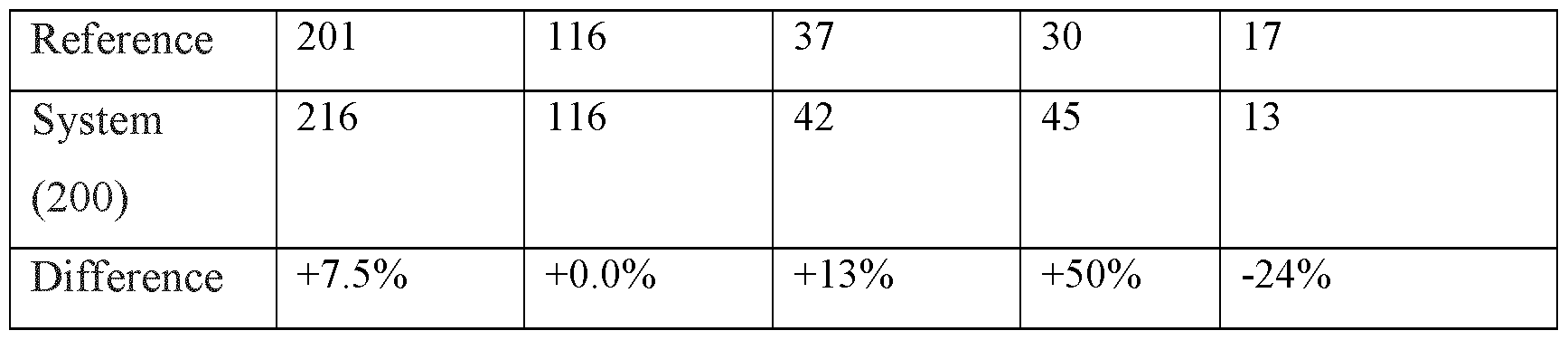
- the system 200 of the present disclosure enables to increase the equipment density significantly, leading to more compact modules requiring less space. This has been achieved while maintaining overall module density substantially the same as historical projects warranting similar congestion and therefore similar operational space, maintenance space and safety distances between equipment. See for instance the table below for an example of the system 200 compared to a state-of-the-art modular reference project:
- Module density (Dmod) Ds (structural density) + Dp (piping density) + Dm (mechanical density) + De (density of 'e&i', i.e. electrical and instrumentation; this relates to electrical cables and equipment such as controllers and transformers).
- the required module volume is determined by, for instance, the equipment types, equipment count, equipment size and equipment spacing, amount of piping and number of mini FARs and substations. Maximization of high-density equipment like PCHEs plays a relatively big role.
- the weight of PCHEs is significantly lower than the weight of shell-and-tube heat exchangers which are used conventionally. The weight may be about a factor 5 lower. Also, the volume of PCHEs is smaller (more than a factor five), resulting in increased equipment density. There is also an impact on piping due to reducti on of parallel configurations.
- the graph of Figure 9 with two lines 460, 462 shows two effects: a) For modules with lower equipment weight, the slope of both curves starts to increase. This indicates that the impact of equipment weight on total module weight decreases. For lower equipment weight, total module weight is determined more by piping, structural weight and other disciplines (for instance, mechanical density decreases). b) As shown in Figure 9, the system 200 of the disclosure has a significantly lower ratio of Mmodi/Mmi than a reference project of a modular built LNG facility, indicating that the system 200 has an increased mechanical density.
- the maximum weight of each module 210, 220, 230, 240 is limited to a predetermined maximum threshold.
- said threshold also referred to as the maximum module weight, is about 5000 or 6000 tonnes.
- Line 456 in Fig. 9 provides an estimation of the 5000 tonnes per module upper threshold. Larger or heavier modules suffer from a relative increase in construction steel with respect to equipment weight. Construction steel refers to the steel and other components required to provide structural strength to a respective module.
- Modules exceeding said threshold will typically increase fabrication time in the yard, with more manhours, which will typically increase the overall project schedule of the project. See Fig. 10.
- the maximum 5000 or 6000 metric tonnes of module weight also simplifies transport, as a relatively large number of vessels or barges is available that can transport modules up to said threshold.
- Figure 10 shows the time it takes to fabricate a module (vertical axis) plotted in dependence of the total weight of the respective module (horizontal axis).
- Entries 480, 482, 484, and 486 respectively indicate data points for practical embodiments of the modules 210, 220, 230 and 240 of the system 200 of the disclosure. Please note that data points close to each other may relate to modules having a different function, but the general trend and trend line can be construed.
- First reference data entries 490 relate to a first reference project.
- Second reference data entries 492 relate to a second reference project.
- the graph of Fig. 10 indicates a correlation, indicated by line 494, between the fabrication time for a respective module and the (total) weight of said module. So, in practice, modules having a lower overall weight can be constructed faster than heavier modules.
- modules having a lower overall weight can be constructed faster than heavier modules.
- Fig. 11 shows a cooling system 500, as included in a preferred embodiment of the system 200 of the disclosure.
- the PCHEs 502, 504, 506 are included in respective primary cooling loops 512, 514, 516.
- PCHEs 502, 504, 506 herein indicate a combination of all heat exchangers in the liquefaction train 200 (see, for instance, Figures 1, 2A, 2B) which cool with respect to a temperature derived from ambient.
- the heat exchangers are preferably printed circuit heat exchangers.
- Fig. 11 only shows the PCHEs schematically, the PCHEs in a respective liquefaction train can be connected to the primary cooling loop in series or in parallel. Preferably the coolers are connected in parallel.
- Some PCHE heat exchangers in the water loop 502, 504 can be connected in series, whereas said series may be connected in parallel to other PCHE heat exchangers or series of PCHE heat exchangers.
- the primary cooling loops 512, 514, 516 may cycle a first coolant, for instance comprising clean water.
- Clean refers to the absence of impurities in the water.
- the clean water herein may refer to softened water or demineralized water.
- additives such as a corrosion inhibitor and antifreeze.
- Anti-freeze herein may comprise glycol.
- the water purity of the clean water may typically be in accordance with an accepted standard, such as EN 12952-12, EN 12953-10, VGB-M 407, or VGB-S-010-T-00.
- Softened water herein refers to water wherein following a water softening process calcium (Ca), magnesium (Mg), and certain other metal cations have been removed.
- demineralized water may be understood to also include reverse osmosis permeate.
- the demineralized water or permeate may have an electrical conductivity of for example 30 pS/cm.
- the clean water may be de-ionized water with an electrical conductivity of about 0.2 to 20 pS/cm, or so-called ultra-pure water with an electrical conductivity of 0.055 pS/cm at most.
- the whole purpose of the clean water in the closed loop is that the fouling of the PCHEs and that scaling of calcium or magnesium carbonates in the PCHEs is prevented.
- the softened water, soft water, or demineralized water reduces or eliminates scale build-up in the PCHEs.
- the primary cooling loops 512, 514, 516 may each be regarded as a Clean Closed Cooling water (CCW) loop.
- CCW Clean Closed Cooling water
- water loops 512, 514 are related to two separate liquefaction trains 200.
- Cooling loop 516 is, as an example, related to heat exchangers 506 not included in a liquefaction train, but elsewhere in the liquefaction facility.
- the primary cooling loops 512, 514, 516 can in turn be cooled with respect to a second coolant of a secondary cooling system 550.
- the second coolant may be cycled in a loop, wherein the system 550 can be regarded as a secondary cooling loop 550.
- the second coolant may comprise seawater or water from cooling towers.
- the second coolant may be air.
- the secondary heat exchangers 540, 542 include air coolers, and the secondary cooling system 550 is formed by said air coolers.
- the secondary loop 550 may comprise a first header 552 for providing the second coolant to the respective heat exchangers 540, 542, 546 via associated conduits 554, 556, 558. Warmed second coolant from the heat exchangers 540, 542, 546 may be collected at a second header 560. From the second header 560, warm second coolant may be provided to a cooler, such as at least one cooling tower or spray tower 570. A first pump 572 can circulate the second coolant in the secondary cooling loop 550. A make-up system 580 may typically be provided to provide additional secondary coolant to top up lost coolant or to add fresh water 582 to control the composition of the coolant. The makeup system may comprise a second pump 584 to pump fresh water 582 from a well or other source to the loop 550, for instance to the cooling tower 570.
- the second coolant can be selected from a group consisting of water from a cooling tower system, sea water, air, or a combination thereof. That is, cooling tower 570 can be replaced or supplemented with sea water or air.
- Fig. 11 also shows ISBL 592 of an LNG production facility which comprises multiple trains 200 as shown.
- the ISBL units in ISBL 592 comprises primary cooling loops 512, 514, and 516 and the associated equipment shown. While not shown, it is understood that ISBL 592 further comprises the ISBL equipment from each train 200, such as the ISBL units illustrated as part of ISBL 202, such as those shown in Figs. 4 and 5 A, and consecutive cooling cycles 4 and 6 and the associated equipment, such as those shown in Figs. 1 and 2A.
- the modules produce at least one process stream 596, 598, 600 that can be cooled further against an ambient temperature.
- train 200 comprises a primary cooling loop 512, 514, 516 to cool at least a process stream 596, 598, 600 from each module 210, and the first mixed refrigerant and the second mixed refrigerant against a first coolant comprising clean water, preferably consisting essentially of clean water.
- the primary cooling loop 512, 514, 516 is a closed clean water cooling loop and the cooling is against an ambient temperature.
- Train 200 comprises a first plurality of heat exchangers through which the primary cooling loop 512, 514, 516 extends.
- the cooling by the primary cooling loop 512, 514, 516 is via heat exchange in at least the first plurality of heat exchangers with respect to the first coolant. More than 50% of the first plurality of heat exchangers are printed circuit heat exchangers 502, 504, 506 which are are adapted to provide at least 80% of the cooling against the ambient temperature. The remaining less than 20% of the cooling duty against ambient temperature can be done using other types of heat exchangers such as ACHEs.
- Fig. 11 shows streams 596, 598, and 600 for each respective train 200 for illustrative purposes of the applicable process streams from the modules and the first and second mixed refrigerants of the particular train 200, as well as any other process streams desirable to be cooled against an ambient temperature via primary cooling loop 512, 514, or 516, respectively.
- Streams 596, 598, and 600 extend through PCHEs 502, 504, and 506, respectively, which represent the more than 50% of the first plurality of heat exchangers through which the primary loop of a particular train 200 extends to provide cooling against an ambient temperature.
- the less than 50% of the first plurality of heat exchangers through which the primary loop extends can be other types of heat exchangers, such as ACHEs.
- Fig. 11 depicts only one PCHE 502, 504, or 506 for a particular train 200, but that train can have any suitable number of PCHEs according to aspects of the facility and systems described herein. That is, train 200 can comprise 10 heat exchangers to cool against ambient, at least six of which would be PCHEs through which the primary cooling loop of train 200 (e.g., 512, 514, or 516) extends, and the at least six PCHEs provide at least 80% of cooling duty with respect to an ambient temperature for that train 200.
- Other trains 200 can have different numbers of heat exchangers for cooling against an ambient temperature consistent with the features described herein, depending on the particular design and/or specification as known to one of ordinary skills.
- FIG. 11 shows a preferred embodiment where the cooling against an ambient temperature by the primary cooling loop 512, 514, or 516 is via secondary loop 550 where the thermal energy from ISBL 592 from the process streams and first and second mixed refrigerants of a respective train 200 is carried by the first coolant is transferred to secondary loop 550 in OSBL 594 and dissipated in OSBL 594.
- the thermal energy transfer from the primary cooling loop 512, 514, 516 to secondary loop 550 is via heat exchange against the second coolant in a second plurality of heat exchangers 540, 542, or 546 through which secondary cooling loop 550 extends.
- Secondary cooling loop 550 comprises a suitable cooler to cool the second coolant against ambient temperature.
- the cooler can be cooling tower 570 as depicted and described herein. While not shown, it is understood that cooling against an ambient temperature by the primary cooling loop 512, 514, 516 can be done without secondary cooling loop 550, such as by routing the first coolant through ACHEs that are located in the OSBL 594.
- the embodiment depicted in Fig. 11 enables the moving of at least 80% of thermal energy from ISBL 592 to the OSBL 594 for dissipation against the ambient temperature in OSBL 594. This is in contrast with other types of heat exchangers, such as ACHEs, particularly ACHEs that are placed on top of ISBL units.
- a train with banks of ACHEs to provide the majority of cooling duty against an ambient temperature dissipates the thermal energy removed by the banks of ACHEs to the environment or ambient in the ISBL rather than in the OSBL, such as OSBL 594, as described herein
- OSBL 594 OSBL 594
- an additional and significant weight reduction for a respective module can be achieved by applying, for instance:
- Figures 12A to 12C provide plan views of exemplary liquefaction systems 200 to scale and for the same total capacity, to allow a comparison of footprint.
- the capacity is, for instance, about 7 mtpa for each of the facilities shown in Figures 12A, 12B and 12C.
- Fig. 12B shows a liquefaction system 650 using state of the art DMR liquefaction technology.
- System 650 has a width W3 and a length L2.
- Total area covered by the system 650 is about 60% of the area covered by the two systems 600 in Fig. 12A.
- Fig. 12C shows two liquefaction systems 200 according to the present disclosure.
- Systems 200 have a width W4 smaller that the width W3 of the system 650.
- Systems 200 have a length L3.
- L2 equals about 2*L3.
- Total area covered by the system 200 is about 40% of the area covered by the two systems 600 in Fig. 12A.
- Figure 13 shows facility 670 for the production of liquefied natural gas, comprising a number of liquefaction trains.
- the facility 670 comprises, for instance, two modular liquefaction trains 650 (see Figure 12B).
- the facility 670 may comprise four liquefaction systems 200 according to the present disclosure (see, for instance, Figure 12C).
- Figure 13 allows a side by side comparison of systems 200 and 650, allowing to put the saving in area (footprint) as mentioned with respect to Figures 12A to 12C into perspective.
- the system 200 of the present disclosure allows to arrange four systems 200 in a matrix.
- a facility comprising one or more liquefaction trains 200 in accordance with the present disclosure allows to increase the LNG production capacity per area with about 50%.
- system 200 compares favorably with respect to state-of-the-art modular facilities. Exemplary parameters are indicated in the table below.
- the number of pieces of equipment for all liquefaction trains combined increases with respect to a reference system.
- the costs of certain individual pieces of equipment may be more expensive.
- Printed Circuit Heat Exchangers are more expensive than traditional Shell and Tube heat exchangers.
- equipment costs are only about 10% of the total installed costs.
- the total procurement costs i.e. the costs to obtain equipment, piping and bulk material (such as valves, etc.) is approximately the same for the system of the present disclosure and several reference projects as referred to herein.
- the total procurement costs represent approximately 20% of the total installed costs of a modular built LNG project.
- the total installed costs of the liquefaction systems according to the present disclosure is about 15 to 20% lower than the total costs to construct a conventional facility including relatively large modular LNG trains.
- Installed costs herein refer to capital expenditure to build the facility, including all liquefaction trains.
- Figure 14 provides another comparison of plot space or footprint between a side-by-side arrangement of two systems 200 according to the invention, with a series of common utility units 750 arranged between the two systems 200.
- the utility units may include, for instance, an MLA unit 760 (Marine Loading Arms, i.e. arms for offloading cargo to a vessel), a fractionation unit 770, and a power generation unit 780.
- the setup may have a width W5 and a length L5.
- the setup of two systems 200 is compared with an exemplary state of the art and modular built liquefaction facility 700 having the same LNG production capacity.
- the system 200 of the disclosure provides significant advantages with respect to weight reduction and footprint reduction. With respect to other measures, the system 200 of the disclosure compared favorably with conventional liquefaction facilities also. See below.
- Greenhouse gas intensity herein is calculated excluding (bar 800) and including (bar 802) the total electrical power requirements, for instance generated by a typical combined cycle powerplant.
- Figure 17 indicates the equipment count per unit of production (typically in mtpa) compared to conventional facilities. Although the capacity for each train of system 200 individually is typically smaller compared to some traditional large (base load) liquefaction trains, the number of pieces of equipment per mtpa still benchmarks top quartile.
- the system of the present disclosure provides significant cost savings, as it deals with substantially all aspects linked to capital expenditure of modular built facilities.
- modular built used to be the norm as offshore used to have a strong focus on available plot space and weight reduction.
- water cooling has been used for cooling in offshore LNG production.
- the system of the present disclosure recognizes that despite abundant plot space and availability of air for cooling, for onshore modular LNG facilities implementing water cooling in combination with relatively light and small equipment, such as printed circuit heat exchangers, provides significant cost savings.
- the system and method of the current disclosure combine features and layout, and modular construction, to achieve optimal benefit and reduction of capital expenditure above and beyond state-of-the-art modular construction for onshore facilities.
- the design of the system 200 of the present disclosure is agnostic for compressors drive.
- the driver of the precool compressor 14 and main compressor 22 may be for instance a gas turbine or an electric motor.
- the site layout and arrangement of modules remains substantially the same.
- Modular LNG concept as disclosed herein combines and integrates various technologies, thus addressing not just one or two, but substantially all levers impacting the capital expenditure to fabricate and build a facility comprising modular built LNG trains.
- the facility of the disclosure allows to significantly reduce the costs of a facility including modular built LNG trains for a comparable total capacity.
- the facility according to the disclosure can have a comparable or better efficiency than conventional facilities, with best in class GHG emissions.
- a process unit herein relates to a unit to perform a specific step of a liquefaction process, such as acid gas removal, dehydration, condensate stabilization. This enables to maximize pre-commissioning at the fabrication yard and minimizing interconnections and hookups between respective modules and hence minimizing work at the production location to interconnect the modules and construct the liquefaction train.
- the refrigerant compressors can be driven by aeroderivative gas turbines or by electric motors. The choice does not change the overall layout of the LNG train of the disclosure.
- the design caters for a wide feed gas composition range and therefore enabling standardization and repeatability across multiple locations - with further potential benefits if using the same fabrication yards, contractors and main equipment vendors.
Landscapes
- Engineering & Computer Science (AREA)
- Physics & Mathematics (AREA)
- Mechanical Engineering (AREA)
- Thermal Sciences (AREA)
- General Engineering & Computer Science (AREA)
- Chemical & Material Sciences (AREA)
- Oil, Petroleum & Natural Gas (AREA)
- Chemical Kinetics & Catalysis (AREA)
- General Chemical & Material Sciences (AREA)
- Separation By Low-Temperature Treatments (AREA)
Abstract
Description



Claims
Priority Applications (3)
| Application Number | Priority Date | Filing Date | Title |
|---|---|---|---|
| US18/250,214 US20230392860A1 (en) | 2020-10-26 | 2021-10-12 | Compact system and method for the production of liquefied natural gas |
| AU2021370108A AU2021370108A1 (en) | 2020-10-26 | 2021-10-12 | Compact system and method for the production of liquefied natural gas |
| CA3199448A CA3199448A1 (en) | 2020-10-26 | 2021-10-12 | Compact system and method for the production of liquefied natural gas |
Applications Claiming Priority (2)
| Application Number | Priority Date | Filing Date | Title |
|---|---|---|---|
| EP20203750.3 | 2020-10-26 | ||
| EP20203750 | 2020-10-26 |
Publications (2)
| Publication Number | Publication Date |
|---|---|
| WO2022089930A2 true WO2022089930A2 (en) | 2022-05-05 |
| WO2022089930A3 WO2022089930A3 (en) | 2022-06-09 |
Family
ID=73014401
Family Applications (1)
| Application Number | Title | Priority Date | Filing Date |
|---|---|---|---|
| PCT/EP2021/078096 Ceased WO2022089930A2 (en) | 2020-10-26 | 2021-10-12 | Compact system and method for the production of liquefied natural gas |
Country Status (4)
| Country | Link |
|---|---|
| US (1) | US20230392860A1 (en) |
| AU (1) | AU2021370108A1 (en) |
| CA (1) | CA3199448A1 (en) |
| WO (1) | WO2022089930A2 (en) |
Families Citing this family (1)
| Publication number | Priority date | Publication date | Assignee | Title |
|---|---|---|---|---|
| IT202100021827A1 (en) * | 2021-08-12 | 2023-02-12 | Nuovo Pignone Tecnologie Srl | Optimized layout of a medium scale liquefied natural gas production unit |
Citations (10)
| Publication number | Priority date | Publication date | Assignee | Title |
|---|---|---|---|---|
| US6370910B1 (en) | 1998-05-21 | 2002-04-16 | Shell Oil Company | Liquefying a stream enriched in methane |
| US6658891B2 (en) | 1999-12-01 | 2003-12-09 | Shell Research Limited | Offshore plant for liquefying natural gas |
| US8521310B2 (en) | 2006-10-31 | 2013-08-27 | Rockwell Automation Technologies, Inc. | Integrated model predictive control of distillation and dehydration sub-processes in a biofuel production process |
| US20140053599A1 (en) | 2012-08-22 | 2014-02-27 | Woodside Energy Technologies Pty Ltd. | Modular LNG Production Facility |
| US20160010916A1 (en) | 2013-03-27 | 2016-01-14 | Woodside Energy Technologies Pty Ltd. | Air-cooled modular lng production facility |
| WO2016150827A1 (en) | 2015-03-20 | 2016-09-29 | Shell Internationale Research Maatschappij B.V. | Process for producing a purified gas stream from natural gas wells |
| US20180311609A1 (en) | 2017-04-28 | 2018-11-01 | Uop Llc | Remote monitoring of adsorber process units |
| WO2019110769A1 (en) | 2017-12-07 | 2019-06-13 | Shell Internationale Research Maatschappij B.V. | Compact lng production train and method |
| WO2019110770A1 (en) | 2017-12-07 | 2019-06-13 | Shell Internationale Research Maatschappij B.V. | Method of operating a liquefied natural gas production facility |
| US20200182552A1 (en) | 2017-05-30 | 2020-06-11 | Shell Oil Company | Method of using an indirect heat exchanger and facility for processing liquefied natural gas comprising such heat exchanger |
Family Cites Families (12)
| Publication number | Priority date | Publication date | Assignee | Title |
|---|---|---|---|---|
| WO2008043806A2 (en) * | 2006-10-11 | 2008-04-17 | Shell Internationale Research Maatschappij B.V. | Method and apparatus for cooling a hydrocarbon stream |
| JP2010535314A (en) * | 2007-07-30 | 2010-11-18 | シエル・インターナシヨネイル・リサーチ・マーチヤツピイ・ベー・ウイ | Method and apparatus for cooling gaseous hydrocarbon streams |
| FR2993643B1 (en) * | 2012-07-17 | 2014-08-22 | Saipem Sa | NATURAL GAS LIQUEFACTION PROCESS WITH PHASE CHANGE |
| WO2015039169A1 (en) * | 2013-09-21 | 2015-03-26 | Woodside Energy Technologies Pty Ltd | Expandable lng processing plant |
| US9709325B2 (en) * | 2013-11-25 | 2017-07-18 | Chevron U.S.A. Inc. | Integration of a small scale liquefaction unit with an LNG plant to convert end flash gas and boil-off gas to incremental LNG |
| NO20140358A1 (en) * | 2014-03-18 | 2015-09-21 | Global Lng Services Ltd | Coastalnear LNG production |
| US20160061516A1 (en) * | 2014-08-29 | 2016-03-03 | Black & Veatch Holding Company | Dual mixed refrigerant system |
| US10443927B2 (en) * | 2015-09-09 | 2019-10-15 | Black & Veatch Holding Company | Mixed refrigerant distributed chilling scheme |
| JP6764020B2 (en) * | 2016-08-16 | 2020-09-30 | エクソンモービル アップストリーム リサーチ カンパニー | Systems and methods for liquefying natural gas using turbine inlet cooling |
| CN110709659B (en) * | 2017-03-14 | 2022-03-08 | 伍德赛德能量科技私人有限公司 | Containerized LNG liquefaction unit and related method for producing LNG |
| RU2645185C1 (en) * | 2017-03-16 | 2018-02-16 | Публичное акционерное общество "НОВАТЭК" | Method of natural gas liquefaction by the cycle of high pressure with the precooling of ethane and nitrogen "arctic cascade" and the installation for its implementation |
| WO2021055021A1 (en) * | 2019-09-19 | 2021-03-25 | Exxonmobil Upstream Research Company | Pretreatment and pre-cooling of natural gas by high pressure compression and expansion |
-
2021
- 2021-10-12 CA CA3199448A patent/CA3199448A1/en active Pending
- 2021-10-12 AU AU2021370108A patent/AU2021370108A1/en active Pending
- 2021-10-12 WO PCT/EP2021/078096 patent/WO2022089930A2/en not_active Ceased
- 2021-10-12 US US18/250,214 patent/US20230392860A1/en active Pending
Patent Citations (10)
| Publication number | Priority date | Publication date | Assignee | Title |
|---|---|---|---|---|
| US6370910B1 (en) | 1998-05-21 | 2002-04-16 | Shell Oil Company | Liquefying a stream enriched in methane |
| US6658891B2 (en) | 1999-12-01 | 2003-12-09 | Shell Research Limited | Offshore plant for liquefying natural gas |
| US8521310B2 (en) | 2006-10-31 | 2013-08-27 | Rockwell Automation Technologies, Inc. | Integrated model predictive control of distillation and dehydration sub-processes in a biofuel production process |
| US20140053599A1 (en) | 2012-08-22 | 2014-02-27 | Woodside Energy Technologies Pty Ltd. | Modular LNG Production Facility |
| US20160010916A1 (en) | 2013-03-27 | 2016-01-14 | Woodside Energy Technologies Pty Ltd. | Air-cooled modular lng production facility |
| WO2016150827A1 (en) | 2015-03-20 | 2016-09-29 | Shell Internationale Research Maatschappij B.V. | Process for producing a purified gas stream from natural gas wells |
| US20180311609A1 (en) | 2017-04-28 | 2018-11-01 | Uop Llc | Remote monitoring of adsorber process units |
| US20200182552A1 (en) | 2017-05-30 | 2020-06-11 | Shell Oil Company | Method of using an indirect heat exchanger and facility for processing liquefied natural gas comprising such heat exchanger |
| WO2019110769A1 (en) | 2017-12-07 | 2019-06-13 | Shell Internationale Research Maatschappij B.V. | Compact lng production train and method |
| WO2019110770A1 (en) | 2017-12-07 | 2019-06-13 | Shell Internationale Research Maatschappij B.V. | Method of operating a liquefied natural gas production facility |
Non-Patent Citations (1)
| Title |
|---|
| T.J. EDWARDS ET AL.: "Analysis of Process Efficiency for Baseload LNG Production", 1984, AIR PRODUCTS AND CHEMICALS INC. |
Also Published As
| Publication number | Publication date |
|---|---|
| AU2021370108A9 (en) | 2024-09-05 |
| CA3199448A1 (en) | 2022-05-05 |
| WO2022089930A3 (en) | 2022-06-09 |
| US20230392860A1 (en) | 2023-12-07 |
| AU2021370108A1 (en) | 2023-05-04 |
Similar Documents
| Publication | Publication Date | Title |
|---|---|---|
| CA2794218C (en) | Modular lng production facility | |
| AU2014245852B2 (en) | Air-cooled modular lng production facility | |
| EP3118548B1 (en) | Integrated methane refrigeration method and system for liquefying natural gas | |
| RU2716099C1 (en) | Modular device for separation of spg and heat exchanger of flash gas | |
| US20100071409A1 (en) | Method and apparatus for liquefying a hydrocarbon stream | |
| JP2020514665A (en) | Method of producing containerized LNG liquefaction unit and related LNG | |
| US20090282862A1 (en) | Method and apparatus for producing a cooled hydrocarbon stream | |
| CN107917577A (en) | The refrigerant cooling means and system of more pressure mixing | |
| US20230392860A1 (en) | Compact system and method for the production of liquefied natural gas | |
| US11162746B2 (en) | Liquid drains in core-in-shell heat exchanger | |
| KR101637334B1 (en) | Method and apparatus for liquefying natural gas | |
| KR101628841B1 (en) | Method and apparatus for liquefying natural gas | |
| AU2013202033A1 (en) | Modular lng production facility | |
| US12523421B2 (en) | Method for producing liquefied natural gas from natural gas, and corresponding plant | |
| JP2020159647A (en) | Natural gas liquefaction device |
Legal Events
| Date | Code | Title | Description |
|---|---|---|---|
| 121 | Ep: the epo has been informed by wipo that ep was designated in this application |
Ref document number: 21790449 Country of ref document: EP Kind code of ref document: A2 |
|
| ENP | Entry into the national phase |
Ref document number: 3199448 Country of ref document: CA |
|
| ENP | Entry into the national phase |
Ref document number: 2021370108 Country of ref document: AU Date of ref document: 20211012 Kind code of ref document: A |
|
| NENP | Non-entry into the national phase |
Ref country code: DE |
|
| 122 | Ep: pct application non-entry in european phase |
Ref document number: 21790449 Country of ref document: EP Kind code of ref document: A2 |
|
| WWE | Wipo information: entry into national phase |
Ref document number: 523440391 Country of ref document: SA |
|
| WWE | Wipo information: entry into national phase |
Ref document number: 523440391 Country of ref document: SA |