WO2022085351A1 - モータ制御装置、機電一体ユニット、ハイブリッドシステム、および電動パワーステアリングシステム - Google Patents
モータ制御装置、機電一体ユニット、ハイブリッドシステム、および電動パワーステアリングシステム Download PDFInfo
- Publication number
- WO2022085351A1 WO2022085351A1 PCT/JP2021/034639 JP2021034639W WO2022085351A1 WO 2022085351 A1 WO2022085351 A1 WO 2022085351A1 JP 2021034639 W JP2021034639 W JP 2021034639W WO 2022085351 A1 WO2022085351 A1 WO 2022085351A1
- Authority
- WO
- WIPO (PCT)
- Prior art keywords
- motor
- control device
- phase
- motor control
- diffusion value
- Prior art date
- Legal status (The legal status is an assumption and is not a legal conclusion. Google has not performed a legal analysis and makes no representation as to the accuracy of the status listed.)
- Ceased
Links
Images


Classifications
-
- H—ELECTRICITY
- H02—GENERATION; CONVERSION OR DISTRIBUTION OF ELECTRIC POWER
- H02P—CONTROL OR REGULATION OF ELECTRIC MOTORS, ELECTRIC GENERATORS OR DYNAMO-ELECTRIC CONVERTERS; CONTROLLING TRANSFORMERS, REACTORS OR CHOKE COILS
- H02P29/00—Arrangements for regulating or controlling electric motors, appropriate for both AC and DC motors
- H02P29/50—Reduction of harmonics
-
- H—ELECTRICITY
- H02—GENERATION; CONVERSION OR DISTRIBUTION OF ELECTRIC POWER
- H02P—CONTROL OR REGULATION OF ELECTRIC MOTORS, ELECTRIC GENERATORS OR DYNAMO-ELECTRIC CONVERTERS; CONTROLLING TRANSFORMERS, REACTORS OR CHOKE COILS
- H02P27/00—Arrangements or methods for the control of AC motors characterised by the kind of supply voltage
- H02P27/04—Arrangements or methods for the control of AC motors characterised by the kind of supply voltage using variable-frequency supply voltage, e.g. inverter or converter supply voltage
- H02P27/06—Arrangements or methods for the control of AC motors characterised by the kind of supply voltage using variable-frequency supply voltage, e.g. inverter or converter supply voltage using DC to AC converters or inverters
- H02P27/08—Arrangements or methods for the control of AC motors characterised by the kind of supply voltage using variable-frequency supply voltage, e.g. inverter or converter supply voltage using DC to AC converters or inverters with pulse width modulation
-
- Y—GENERAL TAGGING OF NEW TECHNOLOGICAL DEVELOPMENTS; GENERAL TAGGING OF CROSS-SECTIONAL TECHNOLOGIES SPANNING OVER SEVERAL SECTIONS OF THE IPC; TECHNICAL SUBJECTS COVERED BY FORMER USPC CROSS-REFERENCE ART COLLECTIONS [XRACs] AND DIGESTS
- Y02—TECHNOLOGIES OR APPLICATIONS FOR MITIGATION OR ADAPTATION AGAINST CLIMATE CHANGE
- Y02T—CLIMATE CHANGE MITIGATION TECHNOLOGIES RELATED TO TRANSPORTATION
- Y02T10/00—Road transport of goods or passengers
- Y02T10/60—Other road transportation technologies with climate change mitigation effect
- Y02T10/64—Electric machine technologies in electromobility
Definitions
- the present invention relates to a motor control device, an integrated mechanical and electrical unit, a hybrid system, and an electric power steering system.
- Permanent magnet synchronous motors do not require a mechanical current rectifying mechanism such as a brush or commutator, are easy to maintain, are compact and lightweight, and have high efficiency and power factor, so they are widely used in driving and power generation of electric vehicles. It is widespread.
- a permanent magnet synchronous motor is composed of a stator composed of an armature coil or the like and a rotor composed of a permanent magnet or an iron core or the like.
- An armature magnetic flux is generated by converting a DC voltage supplied from a DC power source such as a battery into an AC voltage by an inverter and passing an AC current through the armature coil of the permanent magnet synchronous motor using this AC voltage.
- the permanent magnet synchronous motor Due to the magnet torque generated by the attractive and repulsive forces generated between this armature magnetic flux and the magnet magnetic flux of the permanent magnet, and the reluctance torque generated to minimize the magnetoresistance of the armature magnetic flux passing through the rotor.
- the permanent magnet synchronous motor is driven.
- electromagnetic force due to armature magnetic flux and magnet magnetic flux is generated in the direction of rotation (circumferential direction) of the motor and the direction perpendicular to the rotation axis of the motor (radial direction), respectively.
- the above torque is an integral of the electromagnetic force in the circumferential direction, and includes fluctuations in torque (torque pulsation) caused by the structure of the magnetic circuit of the motor.
- the electromagnetic force generated in the radial direction of the motor acts as a vibrating force (electromagnetic vibrating force) that deforms and vibrates the stator and case of the motor.
- the alternating current flowing through the motor includes a fundamental wave current component such as a sine wave, which is used for motor drive control and whose frequency is converted according to the rotation speed of the motor, and a harmonic current component due to the switching operation of the inverter. included.
- the frequency of the harmonic current is determined by the frequency of the fundamental wave current and the frequency of the carrier wave used for PWM modulation. Therefore, depending on the rotation speed of the motor, the electromagnetic vibration force or torque pulsation generated in the motor by the fundamental wave current and the electromagnetic vibration force or torque pulsation generated in the motor by the harmonic current overlap, and large vibration or noise is generated. It may end up.
- Patent Document 1 includes a fundamental wave current corresponding to the rotation speed of a permanent magnet motor and a harmonic current due to a switching operation, and a vibration exciting force periodically generated in the motor by the fundamental wave current at a predetermined motor rotation speed.
- a method of controlling the second phase so that the first phase, which is the phase of the above, and the second phase, which is the phase of the exciting force periodically generated in the motor by the harmonic current, do not overlap with each other is disclosed.
- the present invention has been made in view of the above problems, and an object of the present invention is to effectively suppress vibration and noise generated in a permanent magnet synchronous motor.
- the motor control device is connected to a power converter that converts DC power to AC power, and controls the drive of an AC motor that is driven by using the AC power, and generates a carrier wave.
- a gate signal generation unit for generating is provided, and the phase difference between the voltage command and the carrier wave is randomly changed.
- the mechanical / electrical integrated unit transmits the motor control device, the power converter connected to the motor control device, the AC motor driven by the power converter, and the rotational driving force of the AC motor.
- the AC motor, the power converter, and the gear have an integral structure.
- the hybrid system according to the present invention includes the motor control device, the power converter connected to the motor control device, the AC motor driven by the power converter, and an engine system connected to the AC motor. , Equipped with.
- the electric power steering system according to the present invention includes the motor control device, the power converter connected to the motor control device, and the AC motor driven by the power converter, and the rotation of the AC motor. The driving force is used to assist the driver's steering operation.
- vibration and noise generated by a permanent magnet synchronous motor can be effectively suppressed.
- the block diagram which shows the functional structure of the motor control apparatus which concerns on 1st Embodiment of this invention.
- the block diagram of the carrier frequency adjustment part which concerns on 1st Embodiment of this invention.
- the block diagram of the voltage phase error calculation part which concerns on 1st Embodiment of this invention The block diagram of the carrier phase shift amount diffusion value calculation unit which concerns on 1st Embodiment of this invention.
- the flowchart which shows the arithmetic processing of the voltage phase error arithmetic unit which concerns on 1st Embodiment of this invention. It is a figure which shows the example of the state of each harmonic of the U phase current, and the state of change of the diffusion value by the presence or absence of application of the motor control method of this embodiment.
- FIG. 1 is an overall configuration diagram of a motor drive system including a motor control device according to an embodiment of the present invention.
- the motor drive system 100 includes a motor control device 1, a motor 2, an inverter 3, a high-pressure battery 5, a current detector 7, and a rotation position detector 8.
- the rotation position ⁇ of the motor 2 is input to the motor control device 1 from the rotation position detector 8. Further, Iu, Iv, and Iw representing the three-phase alternating currents flowing through the motor 2 are input from the current detection unit 7, and the torque command T * is input from the upper control device (not shown).
- the motor control device 1 generates a gate signal for controlling the drive of the motor 2 based on these input information, and outputs the gate signal to the inverter 3. This controls the operation of the inverter 3 and controls the drive of the motor 2. The details of the motor control device 1 will be described later.
- the inverter 3 has an inverter circuit 31, a PWM signal drive circuit 32, and a smoothing capacitor 33.
- the PWM signal drive circuit 32 generates a PWM signal for controlling each switching element of the inverter circuit 31 based on the gate signal input from the motor control device 1, and outputs the PWM signal to the inverter circuit 31.
- the inverter circuit 31 has switching elements corresponding to the upper arm and the lower arm of the U phase, the V phase, and the W phase, respectively. By controlling each of these switching elements according to the PWM signal input from the PWM signal drive circuit 32, the DC power supplied from the high-voltage battery 5 is converted into AC power and output to the motor 2.
- the smoothing capacitor 33 smoothes the DC power supplied from the high voltage battery 5 to the inverter circuit 31.
- the high voltage battery 5 is a DC voltage source of the motor drive system 100, and outputs a power supply voltage Hvdc to the inverter 3.
- the power supply voltage Hvdc of the high-voltage battery 5 is converted into a variable voltage and a variable frequency pulsed three-phase AC voltage by the inverter circuit 31 of the inverter 3 and the PWM signal drive circuit 32, and is applied to the motor 2 as a line voltage.
- AC power is supplied from the inverter 3 to the motor 2 based on the DC power of the high-voltage battery 5.
- the power supply voltage Hvdc of the high-voltage battery 5 varies depending on its charging state.
- the motor 2 is a three-phase electric motor that is rotationally driven by AC power supplied from the inverter 3, and has a stator (stator) and a rotor (rotor).
- a permanent magnet synchronous motor is used as the motor 2
- another type of motor 2 such as an induction motor or a synchronous reluctance motor may be used.
- the AC power input from the inverter 3 is applied to the three-phase coils Lu, Lv, and Lw provided in the stator, the three-phase AC currents Iu, Iv, and Iw are conducted in the motor 2, and the magnetic flux is transmitted to each coil. Occurs.
- a torque is generated in the rotor by generating an attractive force / repulsive force between the magnetic flux of each coil and the magnet magnetic flux of the permanent magnet arranged in the rotor, and the motor 2 is rotationally driven.
- the motor 2 is equipped with a rotation position sensor 4 for detecting the rotation position ⁇ of the rotor.
- the rotation position detector 8 calculates the rotation position ⁇ from the input signal of the rotation position sensor 4.
- the calculation result of the rotation position ⁇ by the rotation position detector 8 is input to the motor control device 1, and the AC power generated by the motor control device 1 generating a pulsed gate signal in accordance with the phase of the induced voltage of the motor 2. It is used in the phase control of.
- a resolver composed of an iron core and a winding is more suitable for the rotation position sensor 4, but there is no problem even if it is a magnetic resistance element such as a GMR sensor or a sensor using a Hall element. If the magnetic pole position of the rotor can be measured, any sensor can be used as the rotation position sensor 4. Further, the rotation position detector 8 does not use the input signal from the rotation position sensor 4, but the three-phase AC currents Iu, Iv, Iw flowing through the motor 2 and the three-phase AC voltage Vu applied to the motor 2 from the inverter 3. , Vv, Vw may be used to estimate the rotation position ⁇ .
- a current detection unit 7 is arranged in the current path between the inverter 3 and the motor 2.
- the current detection unit 7 detects three-phase alternating currents Iu, Iv, and Iw (U-phase alternating current Iu, V-phase alternating current Iv, and W-phase alternating current Iw) that energize the motor 2.
- the current detection unit 7 is configured by using, for example, a Hall current sensor or the like.
- the detection results of the three-phase AC currents Iu, Iv, and Iw by the current detection unit 7 are input to the motor control device 1 and used for generating the gate signal performed by the motor control device 1.
- the current detector 7 is composed of three current detectors, the current detectors are two, and the remaining one-phase alternating current is the three-phase alternating currents Iu, Iv, and so on. It may be calculated from the fact that the sum of Iw is zero. Further, the pulsed direct current flowing from the high voltage battery 5 into the inverter 3 is detected by a shunt resistance or the like inserted between the smoothing capacitor 33 and the inverter 3, and this direct current and the inverter 3 are applied to the motor 2. The three-phase AC currents Iu, Iv, and Iw may be obtained based on the three-phase AC voltages Vu, Vv, and Vw.
- FIG. 2 is a block diagram showing a functional configuration of the motor control device 1 according to the first embodiment of the present invention.
- the motor control device 1 includes a current command generation unit 11, a speed calculation unit 12, a three-phase / dq conversion unit 13, a current control unit 14, a dq / three-phase voltage conversion unit 15, and a carrier frequency adjustment. It has each functional block of a unit 16, a triangular wave generation unit 17, and a gate signal generation unit 18.
- the motor control device 1 is configured by, for example, a microcomputer, and these functional blocks can be realized by executing a predetermined program in the microcomputer. Alternatively, a part or all of these functional blocks may be realized by using a hardware circuit such as a logic IC or FPGA.
- the current command generation unit 11 calculates the d-axis current command Id * and the q-axis current command Iq * based on the input torque command T * and the power supply voltage Hvdc.
- the d-axis current commands Id * and q corresponding to the torque command T * are used. Obtain the shaft current command Iq *.
- the speed calculation unit 12 calculates the motor rotation speed ⁇ r, which represents the rotation speed (rotation speed) of the motor 2, from the time change of the rotation position ⁇ .
- the motor rotation speed ⁇ r may be a value represented by either an angular velocity (rad / s) or a rotation speed (rpm). Further, these values may be converted from each other and used.
- the three-phase / dq conversion unit 13 performs dq conversion based on the rotation position ⁇ obtained by the rotation position detector 8 for the three-phase AC currents Iu, Iv, and Iw detected by the current detection unit 7, and the d-axis current. Calculate the value Id and the q-axis current value Iq.
- the current control unit 14 has a d-axis current command Id * and a q-axis current command Iq * output from the current command generation unit 11, and a d-axis current value Id and a q-axis current output from the three-phase / dq conversion unit 13. Based on the deviation from the value Iq, the d-axis voltage command Vd * and the q-axis voltage command Vq * corresponding to the torque command T * are calculated so that these values match.
- the d-axis voltage command Vd *, the q-axis current command Iq *, and the q-axis current value Iq according to the deviation between the d-axis current command Id * and the d-axis current value Id are used.
- the q-axis voltage command Vq * according to the deviation is obtained.
- the dq / three-phase voltage conversion unit 15 converts the d-axis voltage command Vd * and the q-axis voltage command Vq * calculated by the current control unit 14 based on the rotation position ⁇ obtained by the rotation position detector 8. Is performed, and the three-phase voltage commands Vu *, Vv *, and Vw * (U-phase voltage command value Vu *, V-phase voltage command value Vv *, and W-phase voltage command value Vw *) are calculated. As a result, the three-phase voltage commands Vu *, Vv *, and Vw * corresponding to the torque command T * are generated.
- the carrier frequency adjusting unit 16 has a d-axis voltage command Vd * and a q-axis voltage command Vq * generated by the current command generation unit 11, a rotation position ⁇ obtained by the rotation position detector 8, and a rotation speed obtained by the speed calculation unit 12. Based on ⁇ r, the carrier frequency fc representing the frequency of the carrier used to generate the gate signal is calculated. The details of the calculation method of the carrier frequency fc by the carrier frequency adjusting unit 16 will be described later.
- the triangle wave generation unit 17 generates a triangle wave signal (carrier signal) Tr for each of the three-phase voltage commands Vu *, Vv *, and Vw * based on the carrier frequency fc calculated by the carrier frequency adjustment unit 16.
- the gate signal generation unit 18 uses the triangle wave signal Tr output from the triangle wave generation unit 17 to pulse the three-phase voltage commands Vu *, Vv *, and Vw * output from the dq / three-phase voltage conversion unit 15, respectively. It modulates and generates a gate signal for controlling the operation of the inverter 3. Specifically, based on the comparison result between the three-phase voltage commands Vu *, Vv *, Vw * output from the dq / three-phase voltage conversion unit 15 and the triangle wave signal Tr output from the triangle wave generation unit 17, U A pulsed voltage is generated for each of the phase, V phase, and W phase. Then, based on the generated pulsed voltage, a pulsed gate signal for the switching element of each phase of the inverter 3 is generated.
- the gate signals Gup, Gvp, and Gwp of the upper arm of each phase are logically inverted to generate the gate signals Gun, Gvn, and Gwn of the lower arm.
- the gate signal generated by the gate signal generation unit 18 is output from the motor control device 1 to the PWM signal drive circuit 32 of the inverter 3, and is converted into a PWM signal by the PWM signal drive circuit 32.
- each switching element of the inverter circuit 31 is controlled on / off, and the output voltage of the inverter 3 is adjusted.
- FIG. 3 is a diagram illustrating the generation of vibration and noise during driving of the motor 2 and the transmission path thereof.
- the motor 2 is installed in a structure such as a vehicle body by a motor mounting portion.
- shaft vibration torque pulsation
- the vibration force electromagnettic vibration force
- vibration and noise during driving of the motor 2 can be considered to be multiple factors.
- attention is paid to vibration / noise due to electromagnetic force in the circumferential direction and the radial direction of the motor 2, and this is suppressed.
- vibration / noise due to the circumferential and radial electromagnetic forces generated when the motor 2 is driven is input to the vehicle side via a structural transmission system such as a motor mounting portion and vibrates. And make noise.
- the inverter 3 generates a PWM signal based on the gate signal input from the motor control device 1, and switches each switching element of the inverter circuit 31 according to the PWM signal to generate an AC voltage at an arbitrary frequency. It is generated and applied to the motor 2. Due to this AC voltage, an AC current flows in the motor 2, and electromagnetic forces are generated in the circumferential direction and the radial direction, respectively.
- the frequency (switching frequency) of the switching operation of each switching element of the inverter circuit 31 has an upper limit due to restrictions such as switching loss. Therefore, when the frequency of the AC voltage becomes high and approaches the switching frequency, the number of switching pulses per sine wave of the AC voltage is limited according to the upper limit value of the switching frequency.
- the AC voltage applied to the motor 2 tends to be increased in frequency.
- the motor control device 1 of the present embodiment employs synchronous PWM control in which the phases of the triangular wave signal (carrier signal) Tr and the three-phase voltage commands Vu *, Vv *, and Vw * are constant, and the inverter 3 is used. A gate signal is generated for each switching element.
- the switching frequency is fc and the fundamental frequency of the AC voltage applied to the motor 2, that is, the frequencies of the three-phase voltage commands Vu *, Vv *, and Vw * which are sine waves is f1
- the ratio fc / f1 is , Represents the number of switching pulses per sine wave of AC voltage.
- a time harmonic caused by the number of switching pulses fc / f1 is generated in an AC voltage.
- Time harmonic voltages such as time 13th order (fc + 4f1), time 17th order (2fc ⁇ f1), and time 19th order (2fc + f1) are generated. Further, in the dq-axis voltage base obtained by converting these into rotating coordinates, time harmonic voltages such as time 6th order (fc-3f1), time 12th order (fc + 3f1), and time 18th order (2fc) are generated.
- time harmonic voltages such as time 6th order (fc-3f1), time 12th order (fc + 3f1), and time 18th order (2fc) are generated.
- harmonic current causes torque pulsation and pulsation of exciting force in the motor 2, and large vibration and noise may be generated. That is, due to the synchronous PWM control performed by the inverter 3, torque pulsations such as time 6th order (fc-3f1), time 12th order (fc + 3f1), and time 18th order (2fc) are generated in the motor 2.
- FIG. 4 is a diagram illustrating the relationship between the number of switching pulses per sine wave and the time harmonic voltage.
- Tr the frequency analysis result of the generated AC voltage
- the torque pulsation and exciting force pulsation of the motor 2 caused by the time harmonics of the AC voltage as described above have not been dealt with so much in the past due to the limitation of the number of switching pulses. Therefore, the conventional motor control has a problem that vibration / noise proportional to the motor rotation speed is generated during the motor drive by the synchronous PWM control.
- the peak of each order component of the harmonic current generated in the motor 2 is suppressed, and the vibration / noise during the motor drive by the synchronous PWM control is reduced.
- FIG. 5 shows these when the phase difference between the U-phase voltage command Vu * which is a modulated wave and the triangular wave signal Tr which is a carrier wave (hereinafter referred to as “modulated wave / carrier wave phase difference”) is changed. It is a figure which showed the relationship of the voltage waveform.
- FIG. 5A shows a carrier wave and a carrier wave waveform when the modulated wave / carrier wave phase difference is ⁇ 90 deg
- FIG. 5 (b) shows a carrier wave when the modulated wave / carrier wave phase difference is 0 deg.
- the voltage waveform of the modulated wave is shown in FIG.
- the frequency ratio between the modulated wave and the carrier wave is set to 15 for convenience of explanation, but the present invention is not limited to this.
- the U-phase voltage command Vu * is shown as an example of the modulated wave, but other-phase voltage commands, that is, V-phase voltage command Vv * and W-phase voltage command.
- Vw * the phase of the harmonic component other than the fundamental wave component can be freely changed by setting the modulated wave / carrier phase difference as in FIG.
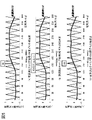
- FIG. 6 shows a harmonic component of the U-phase AC voltage Vu output from the inverter 3 to the motor 2 when the phase difference between the U-phase voltage command Vu *, which is a modulated wave, and the triangular wave signal Tr, which is a carrier wave, is changed.
- 6 (a) shows the modulated wave / carrier phase difference shown in FIGS. 5 (a) to 5 (c), that is, for each harmonic component of the U-phase AC voltage Vu at each phase difference of ⁇ 90 deg, 0 deg, and 90 deg.
- FIG. 6B the phase of each harmonic component of the U-phase AC voltage Vu at each of these phase differences is shown. Note that FIGS.
- FIG. 6 (a) and 6 (b) show the amplitude and phase of the fundamental wave component as the primary component of the U-phase AC voltage Vu, respectively. Further, in FIG. 6B, the phases of the fundamental wave components are shown for each of the 11th, 13th, 17th, 19th, 29th, and 31st harmonic components having relatively large amplitudes in FIG. 6A. The phases when -135 deg are set are shown respectively.
- FIGS. 6 (a) and 6 (b) show the frequency analysis results of the U-phase AC voltage Vu among the three-phase AC voltage output from the inverter 3, but the AC voltage of the other phase, that is, For the V-phase AC voltage Vv and the W-phase AC voltage Vw, the same frequency analysis results as in FIGS. 6 (a) and 6 (b) can be obtained. Therefore, by changing the modulated wave / carrier phase difference, it is possible to arbitrarily change the phase of the harmonic component other than the fundamental wave component of the three-phase AC voltage output from the inverter 3.
- the modulated wave / carrier phase difference is randomly switched at a predetermined timing, thereby diffusing the phase of the time harmonics included in the AC voltage of the motor 2, thereby suppressing the peak of the harmonic current in the motor 2. It can be seen that the vibration and noise generated by the harmonic current can be reduced.
- the carrier frequency adjusting unit 16 determines the carrier frequency fc so as to randomly switch the modulated wave / carrier phase difference at a predetermined timing.
- the carrier wave frequency fc By sequentially controlling the frequency of the triangular wave signal Tr generated by the triangular wave generation unit 17 according to the carrier wave frequency fc, the voltage waveforms of the three-phase voltage commands Vu *, Vv *, and Vw * corresponding to the torque command T * can be obtained. Then, the period and the phase of the triangular wave signal Tr, which is a carrier wave, are adjusted so as to have a desired relationship.
- the desired relationship here is that the triangular wave signal Tr and the three-phase voltage command Vu *, Vv are maintained while maintaining the synchronous PWM control that synchronizes the triangular wave signal Tr with the three-phase voltage commands Vu *, Vv *, and Vw *. It refers to a relationship in which the phase difference between * and Vw * changes randomly.
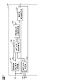
- FIG. 7 is a block diagram of the carrier frequency adjusting unit 16 according to the first embodiment of the present invention.
- the carrier frequency adjusting unit 16 includes a synchronous PWM carrier number selection unit 161, a voltage phase calculation unit 162, a voltage phase error calculation unit 163, a synchronous carrier frequency calculation unit 164, and a carrier frequency setting unit 165.
- the synchronous PWM carrier number selection unit 161 selects the synchronous PWM carrier number Nc representing the number of carriers for one cycle of the voltage waveform in the synchronous PWM control based on the rotation speed ⁇ r.
- the synchronous PWM carrier wave number selection unit 161 may select the synchronous PWM carrier wave number Nc based on the torque command T * as well as the rotation speed ⁇ r. Further, the selection criteria for the number of synchronous PWM carrier waves Nc may be changed depending on whether the rotation speed ⁇ r increases or decreases, for example, by setting hysteresis.
- the voltage phase calculation unit 162 is based on the d-axis voltage command Vd * and the q-axis voltage command Vq *, the rotation position ⁇ , the rotation speed ⁇ r, and the carrier frequency fc, according to the following equations (1) to (4).
- the voltage phase ⁇ v represents the phase of the three-phase voltage commands Vu *, Vv *, and Vw *, which are voltage commands for the inverter 3.
- ⁇ v ⁇ + ⁇ v + ⁇ dqv + 0.5 ⁇ ⁇ ⁇ ⁇ (1)
- ⁇ v ⁇ r ⁇ 1.5Tc ⁇ ⁇ ⁇ (2)
- Tc 1 / fc ...
- ⁇ dqv atan (Vq / Vd) ⁇ ⁇ ⁇ (4)
- ⁇ v represents the calculation delay compensation value of the voltage phase
- Tc represents the carrier wave period
- ⁇ dqv represents the voltage phase from the d-axis.
- ⁇ v a calculation delay of 1.5 control cycles occurs between the time when the rotation position detector 8 acquires the rotation position ⁇ and the time when the motor control device 1 outputs a gate signal to the inverter 3. It is a value that compensates for what you do.
- 0.5 ⁇ is added in the fourth term on the right side of the equation (1). This is an operation for converting the viewpoint to a sine wave because the voltage phase calculated by the first to third terms on the right side of the equation (1) is a cos wave.
- the voltage phase error calculation unit 163 calculates the voltage phase error ⁇ v based on the synchronous PWM carrier wave number Nc selected by the synchronous PWM carrier wave number selection unit 161 and the voltage phase ⁇ v calculated by the voltage phase calculation unit 162.
- the voltage phase error ⁇ v represents the phase difference between the three-phase voltage commands Vu *, Vv *, and Vw *, which are voltage commands for the inverter 3, and the triangular wave signal Tr, which is a carrier wave used for pulse width modulation.
- the voltage phase error calculation unit 163 calculates the voltage phase error ⁇ v at each predetermined calculation cycle, so that the carrier frequency adjustment unit 16 randomly changes the phase difference between the voltage command to the inverter 3 and the carrier wave used for pulse width modulation.
- the frequency of the triangular wave signal Tr can be adjusted so as to be caused.
- the synchronous carrier frequency calculation unit 164 has a voltage phase error ⁇ v calculated by the voltage phase error calculation unit 163 according to the following equation (5), a rotation speed ⁇ r, and a synchronous PWM selected by the synchronous PWM carrier number selection unit 161.
- the synchronous carrier frequency calculation unit 164 can calculate the synchronous carrier frequency fcs based on the equation (5) by, for example, PLL (Phase Locked Loop) control.
- the gain K may be a constant value or may be variable depending on the conditions.
- the carrier frequency setting unit 165 selects either the synchronous carrier frequency fcs calculated by the synchronous carrier frequency calculation unit 164 or the asynchronous carrier frequency fcns based on the rotation speed ⁇ r, and outputs the carrier frequency fc.
- the asynchronous carrier frequency fcss is a constant value preset in the carrier frequency setting unit 165.
- a plurality of asynchronous carrier frequency fcns may be prepared in advance, and one of them may be selected according to the rotation speed ⁇ r.
- the asynchronous carrier frequency fcss can be selected by the carrier frequency setting unit 165 and output as the carrier frequency fc so that the value of the asynchronous carrier frequency fcss increases as the value of the rotation speed ⁇ r increases.
- FIG. 8 is a block diagram of the voltage phase error calculation unit 163 according to the first embodiment of the present invention.
- the voltage phase error calculation unit 163 includes a diffusion value update determination unit 1631, a carrier phase shift amount diffusion value calculation unit 1632, a reference voltage phase calculation unit 1633, an addition unit 1634, and a subtraction unit 1635.
- the diffusion value update determination unit 1631 is based on the voltage phase ⁇ v calculated by the voltage phase calculation unit 162, and the carrier phase shift amount diffusion is calculated by the carrier phase shift amount diffusion value calculation unit 1632 by a method as described below. It is determined whether or not to update the value Dc (hereinafter referred to as "diffusion value Dc"). As a result, when it is determined that the diffusion value Dc is to be updated, the update signal Du is output to the carrier phase shift amount diffusion value calculation unit 1632 so that the diffusion value Dc is updated.
- the carrier frequency adjusting unit 16 performs synchronous PWM control, which is a control for synchronizing the triangular wave signal Tr with the three-phase voltage commands Vu *, Vv *, and Vw *.
- synchronous PWM control the frequency of the triangular wave signal Tr becomes an integral multiple of the frequencies of the three-phase voltage commands Vu *, Vv *, and Vw * according to the synchronous PWM carrier wave number Nc selected by the synchronous PWM carrier wave number selection unit 161.
- the frequency of the triangular wave signal Tr is controlled.
- the diffusion value update determination unit 1631 determines the convergence of the synchronous PWM control based on the voltage phase ⁇ v, and when it is determined that the diffusion value Dc has converged, determines that the diffusion value Dc is to be updated and outputs an update signal Du.
- the amount of change in the voltage phase ⁇ v from the output time of the previous update signal Du is a predetermined designated phase, for example, one of the three-phase voltage commands Vu *, Vv *, and Vw *.
- a predetermined designated phase for example, one of the three-phase voltage commands Vu *, Vv *, and Vw *.
- the voltage phase error ⁇ v is an output value of the voltage phase error calculation unit 163 including the diffusion value update determination unit 1631.
- the synchronous PWM control can be converged by any method. You can judge.
- the timing of the convergence determination of the synchronous PWM control by the diffusion value update determination unit 1631 may be randomly changed. For example, when determining the convergence of the synchronous PWM control based on the amount of change in the voltage phase ⁇ v as described above, the designated phase to be compared with the amount of change in the voltage phase ⁇ v is randomly changed. Alternatively, when determining the convergence of the synchronous PWM control based on the voltage phase error ⁇ v as described above, the range in which the voltage phase error ⁇ v is determined to have converged is randomly changed.
- the value of the gain K is changed in the above-mentioned equation (5) for the synchronous carrier frequency calculation unit 164 to calculate the synchronous carrier frequency fcs. You may do it.
- the carrier phase shift amount diffusion value calculation unit 1632 sets the diffusion value Dc for randomly changing the voltage phase error ⁇ v within a predetermined angle range according to the update signal Du output from the diffusion value update determination unit 1631. Calculate as follows.
- FIG. 9 is a block diagram of the carrier phase shift amount diffusion value calculation unit 1632 according to the first embodiment of the present invention.
- the carrier phase shift amount diffusion value calculation unit 1632 has a random number generator 16321, a previous value holding unit 16322, and a switching unit 16323.
- the random number generator 16321 generates a random number that changes randomly within a predetermined diffusion range corresponding to the above-mentioned modulation wave / carrier phase difference change range.
- a well-known pseudo-random number generation method such as a linear congruential method is used to generate random numbers uniformly distributed within a diffusion range of ⁇ 180 deg around 0.
- a random number weighted according to a specific distribution pattern may be generated instead of a uniform distribution, or the distribution pattern may be changed over time.
- a random number that changes randomly a random number that changes according to a specific change pattern such as a sinusoidal shape may be generated.
- the diffusion range of the random number may be a limited range such as ⁇ 45 deg instead of the entire range ( ⁇ 180 deg) that can be set as the modulated wave / carrier phase difference, or the diffusion range may be changed over time. You may.
- the phase error ⁇ v can be changed randomly. As a result, the peak of the harmonic current in the alternating current flowing through the motor 2 can be reduced in an arbitrary range and magnitude.
- the previous value holding unit 16322 holds the diffusion value Dc previously output by the carrier phase shift amount diffusion value calculation unit 1632.
- the switching unit 16323 selects either the random number generator 16321 or the previous value holding unit 16322 using the update signal Du output from the diffusion value update determination unit 1631, and sets the selected output value as the diffusion value Dc. Output. Specifically, when the update signal Du is output from the diffusion value update determination unit 1631, the diffusion value Dc is updated by outputting the random number generated by the random number generator 16321 as the diffusion value Dc. On the other hand, when the update signal Du is not output from the diffusion value update determination unit 1631, the previous diffusion value Dc held by the previous value holding unit 16322 is output to output the previous diffusion value Dc without updating the diffusion value Dc. Keep the value of.
- the carrier phase shift amount diffusion value calculation unit 1632 calculates the diffusion value Dc as described above. As a result, when the voltage phase error calculation unit 163 determines that the diffusion value Dc is not updated by the diffusion value update determination unit 1631, the carrier phase shift amount diffusion value calculation unit 1632 calculates the previous diffusion value Dc. Can be retained. Further, when the diffusion value update determination unit 1631 determines that the diffusion value Dc is to be updated, the diffusion value Dc may be updated using the calculation result of the diffusion value Dc this time by the carrier phase shift amount diffusion value calculation unit 1632. can.
- FIG. 10 is a diagram showing an example of the calculation result of the diffusion value Dc by the carrier phase shift amount diffusion value calculation unit 1632.
- FIG. 10 shows an example in which the diffusion range of random numbers generated by the random number generator 16321, that is, the diffusion range of the diffusion value Dc is set to ⁇ 180 deg, and the diffusion value Dc uniformly distributed within this diffusion range is calculated.
- each point exemplified by reference numeral 601 represents a diffusion value Dc calculated at predetermined time intervals.
- the reference voltage phase calculation unit 1633 determines the reference voltage phase for determining the phase of the carrier wave in the synchronous PWM control based on the synchronous PWM carrier wave number Nc selected by the synchronous PWM carrier wave number selection unit 161. Calculate ⁇ vb.
- FIG. 11 is a conceptual diagram of the reference voltage phase calculation performed by the reference voltage phase calculation unit 1633.
- the reference voltage phase calculation unit 1633 calculates a reference voltage phase ⁇ vb that changes stepwise between 0 and 2 ⁇ in a number of stages corresponding to the number of synchronous PWM carrier waves Nc.
- the carrier frequency adjusting unit 16 has the carrier frequency adjusting unit 16 only in the valley division section in which the triangular carrier wave rises from the minimum value (valley) to the maximum value (mountain).
- the frequency of the carrier wave can be adjusted.
- the synchronous carrier frequency calculation unit 164 performs synchronous PWM control by sequentially calculating the synchronous carrier frequency fcs from the voltage phase error ⁇ v in the valley division section of the carrier.
- the reference voltage phase calculation unit 1633 calculates the reference voltage phase ⁇ vb used in the calculation of the voltage phase error ⁇ v as a discrete value that changes at ⁇ / 3 intervals as shown in FIG.
- the interval of the reference voltage phase ⁇ vb changes according to the number of synchronous PWM carrier waves Nc. As the number of synchronous PWM carrier waves Nc increases, the interval between the reference voltage phases ⁇ vb becomes smaller.
- the reference voltage phase calculation unit 1633 calculates the reference voltage phase ⁇ vb based on the voltage phase ⁇ v and the number of synchronous PWM carrier waves Nc according to the following equations (6) to (7).
- ⁇ vb int ( ⁇ v / ⁇ s) ⁇ ⁇ s + 0.5 ⁇ s ⁇ ⁇ ⁇ (6)
- ⁇ s 2 ⁇ / Nc ⁇ ⁇ ⁇ (7)
- ⁇ s represents the change width of the voltage phase ⁇ v per carrier wave
- int represents the rounding down operation after the decimal point.
- the equation is expressed in the reference voltage phase calculation unit 1633 so that the reference voltage phase ⁇ vb becomes 0 rad in the mountain split section, which is the section where the triangular carrier wave descends from the maximum value (peak) to the minimum value (valley).
- the reference voltage phase ⁇ vb is calculated according to (6) to (7).
- the period during which the reference voltage phase ⁇ vb becomes 0 rad is not limited to the mountain split section. If the reference voltage phase ⁇ vb that changes stepwise in the number of stages corresponding to the number of synchronous PWM carrier waves Nc between 0 and 2 ⁇ can be calculated using the voltage phase ⁇ v, the calculation method other than the equations (6) to (7) can be used.
- the reference voltage phase calculation unit 1633 may calculate the reference voltage phase ⁇ vb.
- the addition unit 1634 calculates the correction reference voltage phase ⁇ vb2 by adding the diffusion value Dc calculated by the carrier phase shift amount diffusion value calculation unit 1632 to the reference voltage phase ⁇ vb calculated by the reference voltage phase calculation unit 1633. do.
- the correction reference for the voltage phase error ⁇ v so that the modulated wave / carrier phase difference is randomly switched at a predetermined timing to diffuse the phase of each harmonic component of the three-phase voltage commands Vu *, Vv *, and Vw *.
- the voltage phase ⁇ vb2 can be calculated.
- the subtraction unit 1635 subtracts the correction reference voltage phase ⁇ vb2 from the voltage phase ⁇ v and calculates the voltage phase error ⁇ v.
- FIG. 12 is a flowchart showing a calculation process of the voltage phase error calculation unit 163 according to the first embodiment of the present invention.
- step S101 the diffusion value update determination unit 1631 determines whether or not to update the diffusion value Dc. If it is determined to update, the update signal Du is output and the process proceeds to step S102. If it is determined not to update, the process proceeds to step S103.
- step S102 the carrier phase shift amount diffusion value calculation unit 1632 calculates the diffusion value Dc and updates the diffusion value Dc. At this time, the carrier phase shift amount diffusion value calculation unit 1632 selects the random number generated by the random number generator 16321 by the switching unit 16323 according to the update signal Du, and outputs it as the diffusion value Dc. Then, the process proceeds to step S104.
- step S103 the carrier phase shift amount diffusion value calculation unit 1632 holds the previous diffusion value Dc.
- the carrier phase shift amount diffusion value calculation unit 1632 selects the previous diffusion value Dc held by the previous value holding unit 16322 by the switching unit 16323 and outputs it as the diffusion value Dc. Then, the process proceeds to step S104.
- step S104 the reference voltage phase calculation unit 1633 calculates the reference voltage phase ⁇ vb.
- step S105 the diffusion value Dc obtained by the carrier phase shift amount diffusion value calculation unit 1632 in step S102 or S103 by the addition unit 1634 and the subtraction unit 1635, and the reference voltage phase obtained by the reference voltage phase calculation unit 1633 in step S104.
- the voltage phase error ⁇ v is calculated using ⁇ vb.
- the voltage phase error calculation unit 163 calculates the voltage phase error ⁇ v as described above. As a result, the phase difference between the triangle wave signal Tr and the three-phase voltage commands Vu *, Vv *, Vw * is maintained while maintaining the synchronous PWM control that synchronizes the triangle wave signal Tr with the three-phase voltage commands Vu *, Vv *, Vw *.
- the voltage phase error ⁇ v can be determined so as to change randomly.
- the carrier frequency fc can be set so as to suppress the peak of the harmonic current generated in the motor 2 and thereby reduce the torque pulsation and the electromagnetic vibration force.
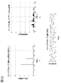
- FIGS. 13 (b) and 14 (b) show an example of the magnitude of each harmonic of the U-phase current for each order component.
- FIGS. 13 (b) and 14 (b) when the motor control method of the present embodiment is applied and the diffusion range of the diffusion value Dc of the triangular wave signal Tr with respect to the U-phase voltage command Vu * is set to ⁇ 180 deg.
- An example of the magnitude of each harmonic of the U-phase current for each order component is shown.
- FIGS. 13 (c) and 14 (c) show the time change of the diffusion value Dc when the diffusion range of the diffusion value Dc is set to ⁇ 180 deg.
- each harmonic contained in the U-phase current is diffused, whereby the peak of the harmonic current is reduced. You can check. Therefore, it can be seen that the effect of reducing the vibration and noise of the motor 2 can be obtained.
- FIGS. 13 and 14 show examples of the triangular wave signal Tr for the U-phase voltage command Vu * when the diffusion value Dc is fixed to 0 and when the triangle wave signal Tr is diffused within a diffusion range of ⁇ 180 deg.
- the harmonic current peak of each phase is similarly spread by spreading the spread value Dc within a predetermined spread range.
- the diffusion range of the diffusion value Dc is not limited to ⁇ 180 deg, and by setting an arbitrary diffusion range, it is possible to reduce the peak of the harmonic current and obtain the effect of reducing the vibration and noise of the motor 2. ..
- the vibration and noise of the motor 2 caused by the time harmonics that become apparent as the number of switching pulses decreases can be realized while avoiding the deterioration of the switching loss of the inverter 3. Therefore, it can contribute to the reduction of vibration and noise of the motor drive system.
- the members for vibration and noise countermeasures such as the vibration damping material and the sound absorbing material, which are required in the conventional motor drive system, can be reduced in the present embodiment, which can contribute to cost reduction and weight reduction.
- the motor control device 1 is connected to an inverter 3 that converts DC power to AC power, and controls the drive of the motor 2 that is driven by using the AC power, and is a triangular wave that is a carrier wave.
- Vv *, Vw * are pulse-width modulated, and a gate signal generation unit 18 for generating a gate signal for controlling the operation of the inverter 3 is provided.
- the motor control device 1 randomly changes the phase difference between the three-phase voltage commands Vu *, Vv *, Vw * and the triangular wave signal Tr. Since this is done, the peak of the harmonic current in the alternating current flowing through the motor 2 can be reduced. As a result, vibration and noise generated by the motor 2 can be effectively suppressed.
- the carrier frequency adjusting unit 16 adjusts the carrier frequency fc so as to randomly change the phase difference between the three-phase voltage commands Vu *, Vv *, Vw * and the triangular wave signal Tr.
- the voltage phase error calculation unit 163 calculates a diffusion value Dc that randomly changes within a predetermined diffusion range, and adjusts the carrier frequency fc based on the diffusion value Dc. Since this is done, it is possible to reliably and easily realize a random change in the phase difference between the three-phase voltage commands Vu *, Vv *, Vw * and the triangular wave signal Tr while maintaining the synchronous PWM control.
- the voltage phase error calculation unit 163 of the carrier frequency adjustment unit 16 determines whether or not to update the diffusion value Dc based on the voltage phase ⁇ v representing the phase of the three-phase voltage commands Vu *, Vv *, and Vw *. It has a diffusion value update determination unit 1631 and a carrier phase shift amount diffusion value calculation unit 1632 for calculating the diffusion value Dc. When it is determined by the diffusion value update determination unit 1631 that the diffusion value Dc is not updated, the calculation result of the previous diffusion value Dc by the carrier phase shift amount diffusion value calculation unit 1632 is retained, and the diffusion value update determination unit 1631 is retained.
- the diffusion value Dc is updated using the calculation result of the diffusion value Dc this time by the carrier phase shift amount diffusion value calculation unit 1632. Since this is done, the diffusion value Dc can be updated at an appropriate timing, and the phase difference between the three-phase voltage commands Vu *, Vv *, Vw * and the triangular wave signal Tr can be randomly changed.
- the diffusion value update determination unit 1631 determines whether or not the synchronous PWM control for synchronizing the triangular wave signal Tr with the three-phase voltage commands Vu *, Vv *, and Vw * has converged based on the voltage phase ⁇ v. When it is determined that the synchronous PWM control has converged, it is determined that the diffusion value Dc is updated. Specifically, the diffusion value update determination unit 1631 determines when the amount of change in the voltage phase ⁇ v exceeds a predetermined designated phase, or the phase difference between the three-phase voltage commands Vu *, Vv *, Vw * and the triangular wave signal Tr. When the voltage phase error ⁇ v representing the above converges within a predetermined range, it is determined that the synchronous PWM control has converged. Since this is done, the diffusion value Dc can be updated at an appropriate timing.
- the motor control device 1 randomly changes the phase difference between the three-phase voltage commands Vu *, Vv *, Vw * and the triangular wave signal Tr within a predetermined range up to a range from ⁇ 180 deg to +180 deg. Let me. Since this is done, the peak of the harmonic current in the alternating current flowing through the motor 2 can be reduced in an arbitrary range and magnitude.
- FIG. 15 is an external perspective view of the mechanical / electrical integrated unit 71 according to the second embodiment.
- the mechanical / electrical integrated unit 71 includes the motor drive system 100 (motor control device 1, motor 2 and inverter 3) described in the first embodiment.
- the motor 2 and the inverter 3 are connected by a coupling portion 713 via a bus bar 712.
- the output of the motor 2 is transmitted to the differential gear (not shown) via the gear 711 and to the axle.
- the motor control device 1 is not shown in FIG. 15, the motor control device 1 can be arranged at an arbitrary position.
- the feature of this mechanical / electrical integrated unit 71 is the structure in which the motor 2, the inverter 3, and the gear 711 are integrated.
- vibration / noise caused by the time harmonics generated by the motor 2 may cause resonance when the inverter 3 or the gear 711 is shaken. In that case, the vibration may occur. ⁇ Noise gets worse.
- the frequency of vibration / noise generated in the motor 2 can be diffused and the peak value thereof can be reduced. It is possible to realize a low vibration and low noise integrated mechanical and electrical unit.
- FIG. 16 is a configuration diagram of the hybrid system 72 according to the third embodiment.
- the hybrid system 72 includes a motor drive system 100 (motor control device 1, motor 2, inverter 3, high-voltage battery 5, current detector 7, rotation position detector 8) described in the first embodiment. ) And a similar motor drive system 101 (motor control device 1, motor 2a, inverter 3a, high-voltage battery 5, current detector 7a, rotation position detector 8a).
- the motor drive systems 100 and 101 share the high voltage battery 5 with the motor control device 1.
- a rotation position sensor 4a for detecting the rotation position ⁇ a of the rotor is attached to the motor 2a.
- the rotation position detector 8a calculates the rotation position ⁇ a from the input signal of the rotation position sensor 4a and outputs it to the motor control device 1.
- a current detection unit 7a is arranged between the inverter 3a and the motor 2a.
- the inverter 3a has an inverter circuit 31a, a PWM signal drive circuit 32a, and a smoothing capacitor 33a.
- the PWM signal drive circuit 32a is connected to a motor control device 1 common to the PWM signal drive circuit 32 of the inverter 3, and each switching element included in the inverter circuit 31a is based on a gate signal input from the motor control device 1.
- a PWM signal for controlling the above is generated and output to the inverter circuit 31a.
- the inverter circuit 31a and the smoothing capacitor 33a are connected to a high voltage battery 5 common to the inverter circuit 31 and the smoothing capacitor 33.
- a torque command T * for the motor 2 and a torque command Ta * for the motor 2a are input to the motor control device 1. Based on these torque commands, the motor control device 1 generates gate signals for controlling the drive of the motors 2 and 2a by the method described in the first embodiment, and outputs the gate signals to the inverters 3 and 3a, respectively. do. That is, the voltage phase error calculation unit 163 of the carrier frequency adjusting unit 16 of the motor control device 1 calculates the voltage phase error ⁇ v so that the vibration and noise generated in the motors 2 and 2a can be suppressed, respectively, to form the carrier wave. Adjust the frequency of the triangular wave signal Tr. In the voltage phase error calculation unit 163, the carrier phase shift amount diffusion value calculation unit 1632 may set different diffusion values Dc for each of the inverters 3 and 3a.
- the engine system 721 and the engine control unit 722 are connected to the motor 2.
- the engine system 721 is driven by the control of the engine control unit 722 to rotate the motor 2.
- the motor 2 operates as a generator by being rotationally driven by the engine system 721 and generates AC power.
- the AC power generated by the motor 2 is converted into DC power by the inverter 3 and charged into the high voltage battery 5.
- the hybrid system 72 can function as a series hybrid system.
- the engine system 721 and the engine control unit 722 may be connectable to the motor 2a.
- the hybrid system 72 of FIG. 16 is realized by using the motor control device 1 described in the first embodiment, whereby the vibration / noise of the motors 2 and 2a caused by the time harmonics is realized.
- the effect of reducing the noise is obtained. Therefore, it is possible to reduce the vibration damping material and sound absorbing material required for vibration / noise countermeasures in the conventional hybrid system.
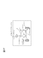
- FIG. 17 is a diagram showing a configuration of an electric power steering system according to a fourth embodiment of the present invention.
- the electric power steering system 61 has a drive control system 75 including the motor control device 1 described in the first embodiment and redundant drive systems 102A and 102B.
- the electric power steering system 61 detects the rotational torque of the steering wheel 62 by the torque sensor 63, and operates the drive control system 75 based on the rotational torque.
- the rotational driving force of the motor 2 possessed by the drive control system 75 is used to generate an assist torque corresponding to the input of the steering wheel 62, which is output to the steering mechanism 65 via the steering assist mechanism 64 for operation.
- the tire 66 is steered by the steering mechanism 65, and the traveling direction of the vehicle is controlled.
- the electric power steering system of a vehicle is directly connected to the driver via the steering wheel, so vibration and noise are easily transmitted to the driver, and the required specifications for vibration and noise are high.
- the electric power steering system 61 of the present embodiment can effectively reduce the vibration in the state where the driver is rotating the steering wheel 62 at high speed, so that the electric power steering system 61 has low vibration and low noise. Can be realized.
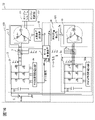
- FIG. 18 is a diagram showing a configuration of a drive control system 75 in the electric power steering system 61 according to the fourth embodiment of the present invention.
- the motor control device 1, the motor 2, and the high-voltage battery 5 are commonly connected to the redundant drive systems 102A and 102B.
- the motor 2 has two winding systems 21 and 22, one winding system 21 constitutes the drive system 102A, and the other winding system 22 constitutes the drive system 102B. ..
- the drive system 102A has an inverter 3 and a rotation position detector 8, and a rotation position sensor 4 for detecting the rotation position ⁇ of the rotor corresponding to the winding system 21 is attached to the motor 2.
- the AC power generated by the inverter 3 flows to the winding system 21 of the motor 2 to rotate and drive the motor 2.
- a current detection unit 7 is arranged between the inverter 3 and the motor 2.
- the drive system 102B has an inverter 3a and a rotation position detector 8a, and a rotation position sensor 4a for detecting the rotation position ⁇ a of the rotor corresponding to the winding system 22 is attached to the motor 2.
- the AC power generated by the inverter 3a flows through the winding system 22 of the motor 2 to rotate and drive the motor 2.
- a current detection unit 7a is arranged between the inverter 3a and the motor 2.
- the inverter 3a, the rotation position detector 8a, the rotation position sensor 4a, and the current detection unit 7a are the same as those in FIG. 16 described in the third embodiment.
- a torque command T * for the motor 2 is input to the motor control device 1.
- the motor control device 1 generates a gate signal for controlling the drive of the motor 2 by the method described in the first embodiment based on the input torque command T *, and outputs the gate signals to the inverters 3 and 3a, respectively. do. That is, the voltage phase error ⁇ v is calculated by the voltage phase error calculation unit 163 of the carrier frequency adjustment unit 16 of the motor control device 1 so that the vibration and noise generated in the drive systems 102A and 102B can be suppressed, respectively, on the carrier wave. Adjust the frequency of a certain triangular wave signal Tr. In the voltage phase error calculation unit 163, the carrier phase shift amount diffusion value calculation unit 1632 may set different diffusion values Dc for each of the inverters 3 and 3a.
- the motor control device 1 described in the first embodiment is used to realize the electric power steering system 61 of FIG. 17, whereby the vibration and noise of the motor 2 caused by the time harmonics are realized.
- the effect of reducing the noise is obtained. Therefore, it is possible to realize an electric power steering system with low vibration and low noise.
- each configuration (FIG. 2, FIG. 7, FIG. 8, FIG. 9, etc.) in the motor control device 1 has a function of each configuration by a CPU and a program, regardless of the configuration by hardware. May be realized.
- this program can be provided by storing it in a storage medium of the motor control device in advance.
- the program can be stored and provided in an independent storage medium, or the program can be recorded and stored in the storage medium of the motor control device by a network line. It may be supplied as a computer-readable computer program product in various forms such as a data signal (carrier wave).
- the present invention is not limited to the above-described embodiment, and other embodiments considered within the scope of the technical idea of the present invention are also included within the scope of the present invention as long as the features of the present invention are not impaired. .. Further, the configuration may be a combination of the above-mentioned plurality of embodiments.
Landscapes
- Engineering & Computer Science (AREA)
- Power Engineering (AREA)
- Control Of Ac Motors In General (AREA)
- Inverter Devices (AREA)
Priority Applications (4)
| Application Number | Priority Date | Filing Date | Title |
|---|---|---|---|
| CN202180071528.6A CN116368716A (zh) | 2020-10-21 | 2021-09-21 | 马达控制装置、机电一体单元、混合动力系统以及电动助力转向系统 |
| JP2022557307A JP7431346B2 (ja) | 2020-10-21 | 2021-09-21 | モータ制御装置、機電一体ユニット、ハイブリッドシステム、および電動パワーステアリングシステム |
| US18/249,299 US12301148B2 (en) | 2020-10-21 | 2021-09-21 | Motor control device, electro-mechanical integrated unit, hybrid system, and electric power steering system |
| DE112021004405.2T DE112021004405T5 (de) | 2020-10-21 | 2021-09-21 | Motorsteuervorrichtung, elektromechanische integrierte einheit, hybridsystem und elektrisches servolenkungssystem |
Applications Claiming Priority (2)
| Application Number | Priority Date | Filing Date | Title |
|---|---|---|---|
| JP2020176806 | 2020-10-21 | ||
| JP2020-176806 | 2020-10-21 |
Publications (1)
| Publication Number | Publication Date |
|---|---|
| WO2022085351A1 true WO2022085351A1 (ja) | 2022-04-28 |
Family
ID=81289802
Family Applications (1)
| Application Number | Title | Priority Date | Filing Date |
|---|---|---|---|
| PCT/JP2021/034639 Ceased WO2022085351A1 (ja) | 2020-10-21 | 2021-09-21 | モータ制御装置、機電一体ユニット、ハイブリッドシステム、および電動パワーステアリングシステム |
Country Status (5)
| Country | Link |
|---|---|
| US (1) | US12301148B2 (https=) |
| JP (1) | JP7431346B2 (https=) |
| CN (1) | CN116368716A (https=) |
| DE (1) | DE112021004405T5 (https=) |
| WO (1) | WO2022085351A1 (https=) |
Families Citing this family (4)
| Publication number | Priority date | Publication date | Assignee | Title |
|---|---|---|---|---|
| JP7623922B2 (ja) * | 2021-09-30 | 2025-01-29 | 日立Astemo株式会社 | インバータ制御装置、ハイブリッドシステム、機電一体ユニット、電動車両システム、インバータ制御方法 |
| WO2023073816A1 (ja) * | 2021-10-26 | 2023-05-04 | 日立Astemo株式会社 | モータ制御装置、モータ制御方法、ハイブリッドシステム、昇圧コンバータシステム、電動パワーステアリングシステム |
| WO2023073870A1 (ja) * | 2021-10-28 | 2023-05-04 | 三菱電機株式会社 | 電力変換装置、モータ駆動装置および冷凍サイクル適用機器 |
| WO2023073880A1 (ja) * | 2021-10-28 | 2023-05-04 | 三菱電機株式会社 | 電力変換装置、モータ駆動装置および冷凍サイクル適用機器 |
Citations (6)
| Publication number | Priority date | Publication date | Assignee | Title |
|---|---|---|---|---|
| JP2006136138A (ja) * | 2004-11-08 | 2006-05-25 | Nissan Motor Co Ltd | パルス幅変調信号駆動機器の制御装置 |
| US20070247091A1 (en) * | 2003-07-22 | 2007-10-25 | Maiocchi Sergio A | System for Operating Dc Motors and Power Converters |
| WO2010137162A1 (ja) * | 2009-05-29 | 2010-12-02 | トヨタ自動車株式会社 | 交流電動機の制御装置および制御方法 |
| WO2016098410A1 (ja) * | 2014-12-15 | 2016-06-23 | 日立オートモティブシステムズ株式会社 | 電力変換装置及びこれを用いた電動パワーステアリング装置 |
| US20170025929A1 (en) * | 2015-07-21 | 2017-01-26 | Stmicroelectronics S.R.L. | Method of controlling electric motors, corresponding system, electric motor and computer program product |
| JP2018004246A (ja) * | 2017-08-28 | 2018-01-11 | 三菱電機株式会社 | ヒートポンプ装置 |
Family Cites Families (1)
| Publication number | Priority date | Publication date | Assignee | Title |
|---|---|---|---|---|
| CN110235357B (zh) | 2017-01-30 | 2022-12-13 | 日立安斯泰莫株式会社 | 逆变器控制装置 |
-
2021
- 2021-09-21 WO PCT/JP2021/034639 patent/WO2022085351A1/ja not_active Ceased
- 2021-09-21 US US18/249,299 patent/US12301148B2/en active Active
- 2021-09-21 JP JP2022557307A patent/JP7431346B2/ja active Active
- 2021-09-21 CN CN202180071528.6A patent/CN116368716A/zh active Pending
- 2021-09-21 DE DE112021004405.2T patent/DE112021004405T5/de active Pending
Patent Citations (6)
| Publication number | Priority date | Publication date | Assignee | Title |
|---|---|---|---|---|
| US20070247091A1 (en) * | 2003-07-22 | 2007-10-25 | Maiocchi Sergio A | System for Operating Dc Motors and Power Converters |
| JP2006136138A (ja) * | 2004-11-08 | 2006-05-25 | Nissan Motor Co Ltd | パルス幅変調信号駆動機器の制御装置 |
| WO2010137162A1 (ja) * | 2009-05-29 | 2010-12-02 | トヨタ自動車株式会社 | 交流電動機の制御装置および制御方法 |
| WO2016098410A1 (ja) * | 2014-12-15 | 2016-06-23 | 日立オートモティブシステムズ株式会社 | 電力変換装置及びこれを用いた電動パワーステアリング装置 |
| US20170025929A1 (en) * | 2015-07-21 | 2017-01-26 | Stmicroelectronics S.R.L. | Method of controlling electric motors, corresponding system, electric motor and computer program product |
| JP2018004246A (ja) * | 2017-08-28 | 2018-01-11 | 三菱電機株式会社 | ヒートポンプ装置 |
Also Published As
| Publication number | Publication date |
|---|---|
| JP7431346B2 (ja) | 2024-02-14 |
| JPWO2022085351A1 (https=) | 2022-04-28 |
| CN116368716A (zh) | 2023-06-30 |
| US12301148B2 (en) | 2025-05-13 |
| US20230402953A1 (en) | 2023-12-14 |
| DE112021004405T5 (de) | 2023-06-15 |
Similar Documents
| Publication | Publication Date | Title |
|---|---|---|
| JP7280170B2 (ja) | モータ制御装置、モータ制御方法、ハイブリッドシステム、昇圧コンバータシステム、電動パワーステアリングシステム | |
| JP4205157B1 (ja) | 電動機の制御装置 | |
| JP7431346B2 (ja) | モータ制御装置、機電一体ユニット、ハイブリッドシステム、および電動パワーステアリングシステム | |
| JP7372871B2 (ja) | モータ制御装置、機電一体ユニット、電動車両システム、モータ制御方法 | |
| JP5916526B2 (ja) | 電力変換器制御装置および多重巻線型電動機駆動装置 | |
| WO2018139295A1 (ja) | インバータ制御装置 | |
| WO2013021998A1 (ja) | 制御装置 | |
| JP7623922B2 (ja) | インバータ制御装置、ハイブリッドシステム、機電一体ユニット、電動車両システム、インバータ制御方法 | |
| JP7494393B2 (ja) | モータ制御装置、機電一体ユニット、ハイブリッドシステム、電動パワーステアリングシステム、およびモータ制御方法 | |
| JP6742393B2 (ja) | 電力変換装置、発電電動機の制御装置、および、電動パワーステアリング装置 | |
| JP7493429B2 (ja) | モータ制御装置、機電一体ユニット、昇圧コンバータシステム、ハイブリッドシステム、電動車両システム、および電気鉄道車両 | |
| JP2011036078A (ja) | モータ制御装置 | |
| JP6459878B2 (ja) | 回転電機の制御装置 | |
| JP7797520B2 (ja) | モータ制御装置、およびモータ制御方法 | |
| US12199539B2 (en) | Motor control device, electric vehicle, and motor control method | |
| JP7703677B2 (ja) | モータ制御装置、モータ制御方法、ハイブリッドシステム、昇圧コンバータシステム、電動パワーステアリングシステム | |
| JP2012044775A (ja) | モータ駆動制御装置 | |
| WO2024157363A1 (ja) | 電動機制御装置および電動機制御方法 | |
| JP2025039249A (ja) | 回転電機制御方法、及び、回転電機制御装置 | |
| WO2023195172A1 (ja) | モータ制御装置、モータ制御方法 |
Legal Events
| Date | Code | Title | Description |
|---|---|---|---|
| 121 | Ep: the epo has been informed by wipo that ep was designated in this application |
Ref document number: 21882492 Country of ref document: EP Kind code of ref document: A1 |
|
| ENP | Entry into the national phase |
Ref document number: 2022557307 Country of ref document: JP Kind code of ref document: A |
|
| 122 | Ep: pct application non-entry in european phase |
Ref document number: 21882492 Country of ref document: EP Kind code of ref document: A1 |
|
| WWG | Wipo information: grant in national office |
Ref document number: 18249299 Country of ref document: US |