WO2022079957A1 - プラスチックシンチレーションファイバ及びその製造方法 - Google Patents
プラスチックシンチレーションファイバ及びその製造方法 Download PDFInfo
- Publication number
- WO2022079957A1 WO2022079957A1 PCT/JP2021/025035 JP2021025035W WO2022079957A1 WO 2022079957 A1 WO2022079957 A1 WO 2022079957A1 JP 2021025035 W JP2021025035 W JP 2021025035W WO 2022079957 A1 WO2022079957 A1 WO 2022079957A1
- Authority
- WO
- WIPO (PCT)
- Prior art keywords
- layer
- core
- outermost
- fiber
- clad layer
- Prior art date
- Legal status (The legal status is an assumption and is not a legal conclusion. Google has not performed a legal analysis and makes no representation as to the accuracy of the status listed.)
- Ceased
Links
Images


Classifications
-
- G—PHYSICS
- G01—MEASURING; TESTING
- G01T—MEASUREMENT OF NUCLEAR OR X-RADIATION
- G01T1/00—Measuring X-radiation, gamma radiation, corpuscular radiation, or cosmic radiation
- G01T1/16—Measuring radiation intensity
- G01T1/20—Measuring radiation intensity with scintillation detectors
- G01T1/201—Measuring radiation intensity with scintillation detectors using scintillating fibres
-
- B—PERFORMING OPERATIONS; TRANSPORTING
- B29—WORKING OF PLASTICS; WORKING OF SUBSTANCES IN A PLASTIC STATE IN GENERAL
- B29D—PRODUCING PARTICULAR ARTICLES FROM PLASTICS OR FROM SUBSTANCES IN A PLASTIC STATE
- B29D11/00—Producing optical elements, e.g. lenses or prisms
- B29D11/00663—Production of light guides
- B29D11/00701—Production of light guides having an intermediate layer between core and cladding
-
- C—CHEMISTRY; METALLURGY
- C09—DYES; PAINTS; POLISHES; NATURAL RESINS; ADHESIVES; COMPOSITIONS NOT OTHERWISE PROVIDED FOR; APPLICATIONS OF MATERIALS NOT OTHERWISE PROVIDED FOR
- C09K—MATERIALS FOR MISCELLANEOUS APPLICATIONS, NOT PROVIDED FOR ELSEWHERE
- C09K11/00—Luminescent materials, e.g. electroluminescent or chemiluminescent
- C09K11/08—Luminescent materials, e.g. electroluminescent or chemiluminescent containing inorganic luminescent materials
- C09K11/66—Luminescent materials, e.g. electroluminescent or chemiluminescent containing inorganic luminescent materials containing germanium, tin or lead
-
- C—CHEMISTRY; METALLURGY
- C09—DYES; PAINTS; POLISHES; NATURAL RESINS; ADHESIVES; COMPOSITIONS NOT OTHERWISE PROVIDED FOR; APPLICATIONS OF MATERIALS NOT OTHERWISE PROVIDED FOR
- C09K—MATERIALS FOR MISCELLANEOUS APPLICATIONS, NOT PROVIDED FOR ELSEWHERE
- C09K11/00—Luminescent materials, e.g. electroluminescent or chemiluminescent
- C09K11/08—Luminescent materials, e.g. electroluminescent or chemiluminescent containing inorganic luminescent materials
- C09K11/74—Luminescent materials, e.g. electroluminescent or chemiluminescent containing inorganic luminescent materials containing arsenic, antimony or bismuth
-
- G—PHYSICS
- G02—OPTICS
- G02B—OPTICAL ELEMENTS, SYSTEMS OR APPARATUS
- G02B1/00—Optical elements characterised by the material of which they are made; Optical coatings for optical elements
- G02B1/04—Optical elements characterised by the material of which they are made; Optical coatings for optical elements made of organic materials, e.g. plastics
- G02B1/045—Light guides
- G02B1/046—Light guides characterised by the core material
-
- G—PHYSICS
- G02—OPTICS
- G02B—OPTICAL ELEMENTS, SYSTEMS OR APPARATUS
- G02B1/00—Optical elements characterised by the material of which they are made; Optical coatings for optical elements
- G02B1/04—Optical elements characterised by the material of which they are made; Optical coatings for optical elements made of organic materials, e.g. plastics
- G02B1/045—Light guides
- G02B1/048—Light guides characterised by the cladding material
-
- G—PHYSICS
- G02—OPTICS
- G02B—OPTICAL ELEMENTS, SYSTEMS OR APPARATUS
- G02B6/00—Light guides; Structural details of arrangements comprising light guides and other optical elements, e.g. couplings
- G02B6/02—Optical fibres with cladding with or without a coating
- G02B6/036—Optical fibres with cladding with or without a coating core or cladding comprising multiple layers
- G02B6/03616—Optical fibres characterised both by the number of different refractive index layers around the central core segment, i.e. around the innermost high index core layer, and their relative refractive index difference
- G02B6/03622—Optical fibres characterised both by the number of different refractive index layers around the central core segment, i.e. around the innermost high index core layer, and their relative refractive index difference having 2 layers only
Definitions
- the present invention relates to a plastic scintillation fiber and a method for manufacturing the same.
- the conventional plastic scintillation fiber is a plastic fiber in which the outer peripheral surface of the core, which is a scintillator, is covered with a clad layer having a lower refractive index than the core, and is mainly used for radiation detection.
- the core is composed of a polymer material obtained by adding an organic phosphor to a substrate having an aromatic ring such as polystyrene or polyvinyltoluene.
- the clad layer is composed of a low refractive index polymer material such as polymethylmethacrylate or fluorine-containing polymethylmethacrylate.
- the core base material of the scintillation fiber has an aromatic ring, and when the irradiated radiation crosses the scintillation fiber, it absorbs a part of the energy by re-radiation of secondary particles in the core and emits it as ultraviolet rays. It has the characteristic of doing. If no phosphor is added to the core substrate, this ultraviolet ray is self-absorbed by the core substrate itself and disappears without being transmitted in the core.
- this ultraviolet ray is absorbed by the phosphor added to the core base material, and the light having a longer wavelength is re-emitted. Therefore, by selecting an appropriate phosphor, it is converted into light having a long wavelength such as blue, which is difficult to be self-absorbed by the core substrate, and transmitted in the fiber.
- the light transmitted in the fiber is detected by a detector connected to one end or both ends.
- the scintillation fiber has two functions of light emission by radiation detection and optical transmission, and is used for applications such as calculating the passing position and amount of radiation.
- it is important how to efficiently convert the ultraviolet light emitted from the core into a long wavelength and transmit it over a long distance.
- plastic wavelength conversion fiber (WLSF: Wavelength Shifting Fiber) is often used alongside scintillation fiber.
- the wavelength conversion fiber is used in combination with, for example, a plastic scintillator that emits blue light. Grooves and holes are provided in a plate-shaped or rod-shaped plastic scintillator, and a wavelength conversion fiber that absorbs blue light and converts it into green light is embedded.
- wavelength conversion fiber that is thin, easy to bend, and capable of long-distance transmission is preferably used.
- a large number of wavelength conversion fibers can be freely laid out up to an external photoelectric detector.
- the core of the wavelength conversion fiber is made of polystyrene resin or polymethylmethacrylate resin, and a fluorescent substance for wavelength conversion (hereinafter, also referred to as "wavelength conversion fluorescent substance") is dissolved.
- a fluorescent substance for wavelength conversion hereinafter, also referred to as "wavelength conversion fluorescent substance"
- the scintillation light incident from the external scintillator is absorbed by the phosphor in the core, and the wavelength is efficiently converted and transmitted in the fiber.
- the scintillator to be combined with the wavelength conversion fiber not only a plastic scintillator but also an inorganic scintillator having high detection sensitivity for X-rays, ⁇ -rays and the like is used.
- the wavelength conversion fiber can easily collect the scintillation light emitted from a large-area or long scintillator.
- the wavelength conversion fiber can transmit the wavelength-converted light in the core and freely connect to the photoelectric detector.
- Inorganic scintillators include BaF 2 , CsI, CaF 2 , CeF 3 , Bi 4 Ge 3 O 12 , Y 2 SiO 5 , Y 3 All 5 O 12 , Bi 4 Ge 3 O 12 , PbWO 4 , CdWO 4 , Gd 2 . Many are known such as SiO 5 : Ce 3+ , Lu 2 SiO 5 : Ce 3+ .
- the inorganic scintillator has an attenuation length of several mm and is not highly transparent, and cannot transmit emitted light (that is, scintillation light) over a long distance.
- emitted light that is, scintillation light
- it is difficult to optically transmit to a photoelectric detector by an inorganic scintillator due to the limitation of crystal size.
- Non-Patent Document 1 there is a case where the detection sensitivity to X-rays and ⁇ -rays is improved by adding a lead compound or the like to a plastic scintillator.
- a lead compound or the like to a plastic scintillator.
- the concentration of heavy metal elements added increases, the permeability of the plastic scintillator decreases, so it is not suitable for use in large sizes.
- the wavelength conversion fiber is placed along the end face and the surface of the scintillator, and the wavelength conversion fiber is used for optical transmission to the photoelectric detector.
- the detected light can be transmitted over a longer distance.
- a large number of post-processings in which a scintillator and a wavelength conversion fiber are combined are required for detection that emphasizes spatial resolution, such as image detection disclosed in Patent Document 2.
- the core itself is required to have high transparency because it emits scintillation light and also transmits light to the photoelectric detector. Therefore, it is not possible to obtain a plastic scintillation fiber having enhanced detection sensitivity to X-rays and ⁇ -rays by including a compound containing a heavy metal element in the core in order to increase the interaction probability of X-rays and ⁇ -rays.
- the present invention has been made in view of such circumstances, and an object of the present invention is to provide a plastic scintillation fiber capable of detecting X-rays and ⁇ -rays with high sensitivity and having excellent productivity.
- the plastic scintillation fiber according to one aspect of the present invention is The outermost layer containing a compound of heavy metal elements and containing a scintillating resin, and A core provided inside the outermost layer and containing at least one kind of phosphor that absorbs the scintillation light generated in the outermost layer and converts the wavelength into a long wavelength.
- a clad layer that covers the outer peripheral surface of the core and has a lower refractive index than the core is provided.
- the wavelength conversion fiber including the core and the clad layer and the outermost peripheral layer covering the outer peripheral surface of the wavelength conversion fiber are integrally formed.
- plastic scintillation fiber When a plastic scintillation fiber is irradiated with X-rays or ⁇ -rays, charged particles such as electrons or positrons are generated by interactions such as the photoelectric effect, Compton effect, and electron pair generation, and emit light by scintillation. Since the plastic scintillation fiber of the present invention contains a compound of a heavy metal element in the outermost peripheral layer, the probability of the above interaction is improved, and the detection sensitivity to X-rays and ⁇ -rays is improved as compared with the conventional plastic scintillation fiber.
- the outermost layer does not need the high transparency required for transmitting light as in the core, a compound of a heavy metal element can be added at a high concentration.
- the wavelength conversion fiber including the core and the clad layer and the outermost peripheral layer covering the outer peripheral surface of the wavelength conversion fiber are integrally formed, post-processing for combining the scintillator and the wavelength conversion fiber, which has been conventionally required, is unnecessary. Will be. That is, it is possible to provide a plastic scintillation fiber having high detection sensitivity to X-rays and ⁇ -rays and excellent productivity.
- the outermost layer may contain at least one kind of phosphor that absorbs the scintillation light and converts the wavelength into a long wavelength.
- the heavy metal element may be lead or bismuth. Further, in the outermost layer, the compound of the heavy metal element may be copolymerized with the resin having scintillation property.
- the wavelength conversion fiber and the outermost peripheral layer may be integrally formed by drawing. This further improves productivity.
- a protective layer that protects the outermost layer may be integrally formed on the outer side of the outermost layer. This improves durability and the like.
- the clad layer may have a multi-clad structure including an inner clad layer and an outer clad layer that covers the outer peripheral surface of the inner clad layer and has a lower refractive index than the inner clad layer. .. As a result, the total reflection angle becomes wider and the light emission becomes higher.
- a reflective layer may be provided outside the outermost layer or the protective layer.
- the scintillation light emitted from the outermost peripheral layer and the light wavelength-converted by the core are reflected by the reflective layer, so that the light is less likely to leak from the side surface of the fiber to the outside, resulting in high emission.
- the reflective film may be a metal film. With this configuration, high reflectance can be obtained with a thin thickness.
- the metal film since the metal film has a high probability of interacting with X-rays and ⁇ -rays, increasing the thickness improves the sensitivity to X-rays and ⁇ -rays, and also improves the wavelength-converted light in the core and the outermost layer.
- the utilization efficiency of the scintillation light emitted in 1 is also improved, and high emission can be achieved.
- the method for manufacturing a plastic scintillation fiber is as follows.
- the outermost layer containing a compound of heavy metal elements and containing a scintillating resin, and A core provided inside the outermost layer and containing at least one kind of phosphor that absorbs the scintillation light generated in the outermost layer and converts the wavelength into a long wavelength.
- a method for manufacturing a plastic scintillation fiber comprising: a clad layer having a refractive index lower than that of the core while covering the outer peripheral surface of the core.
- the present invention comprises a step of drawing a line while heating the preform.
- the method for manufacturing a plastic scintillation fiber according to one aspect of the present invention is as follows.
- the outermost layer containing a compound of heavy metal elements and containing a scintillating resin, and A core provided inside the outermost layer and containing at least one kind of phosphor that absorbs the scintillation light generated in the outermost layer and converts the wavelength into a long wavelength.
- a method for manufacturing a plastic scintillation fiber comprising: a clad layer having a refractive index lower than that of the core while covering the outer peripheral surface of the core.
- the outermost peripheral layer is coated on the surface of the wavelength conversion fiber including the core and the clad layer.
- FIG. It is sectional drawing of the plastic scintillation fiber which concerns on Embodiment 1.
- FIG. It is sectional drawing of the plastic scintillation fiber which concerns on the modification of Embodiment 1.
- FIG. It is sectional drawing of the plastic scintillation fiber which concerns on other modification of Embodiment 1.
- FIG. It is a perspective view which shows the manufacturing method of the plastic scintillation fiber which concerns on Embodiment 1.
- FIG. It is a perspective view which shows the application example of the scintillation fiber which concerns on Embodiment 1.
- FIG. It is the emission spectrum of the paraterphenyl added to the outermost layer and the absorption and emission spectra of the wavelength conversion phosphor BBOT.
- FIG. 1 is a cross-sectional view of the plastic scintillation fiber according to the first embodiment.
- the plastic scintillation fiber according to the first embodiment includes an outermost peripheral layer 1, a core 2, and a clad layer 3.
- the outermost peripheral layer 1 contains a compound of a heavy metal element and is made of a scintillating resin.
- the resin is a transparent resin containing a compound of a heavy metal element and a phosphor that absorbs scintillation light emitted from the resin and converts it into a long wavelength.
- the heavy metal element is a metal element having a specific gravity of 4 or more by itself.
- the outermost peripheral layer 1 may sufficiently emit light and be transparent to the extent that scintillation light penetrates the clad layer 3 and is incident on the core 2 in the center, and high transparency is not required, but it is as transparent as possible. It is desirable to have.
- the thickness of the outermost peripheral layer 1 may be increased in order to obtain the required detection sensitivity to X-rays and ⁇ -rays. Even if the outermost layer 1 which is a scintillator layer has low transparency, long-distance transmission is possible if the core 2 at the center, which is responsible for optical transmission, has high transparency.
- the core 2 is made of a transparent resin having a high refractive index, which is provided inside the outermost layer 1 and contains at least one kind of phosphor that absorbs the scintillation light generated in the outermost layer 1 and converts it into a longer wavelength. Become.
- the refractive index of the transparent resin constituting the core 2 is preferably 1.5 or more.
- the clad layer 3 covers the outer peripheral surface of the core 2 and is made of a transparent resin having a lower refractive index than the core 2.
- the wavelength conversion fiber composed of the core 2 and the clad layer 3 and the outermost peripheral layer 1 covering the outer peripheral surface of the wavelength conversion fiber are integrally formed.
- the transparency of the clad layer 3 is as important as the transparency of the core 2.
- the transparency of the outermost layer 1 is not so important.
- the thickness of the clad layer 3 is preferably 3 ⁇ m to 100 ⁇ m, which is sufficiently thicker than the depth of the evanescent wave in which the transmitted light exudes from the core to the clad layer 3.
- the thickness of the clad layer 3 may be sufficiently thicker than the depth of the evanescent wave exuding into the clad layer 3.
- the core 2 may include a second phosphor for further wavelength conversion in order to match the wavelength sensitivity of a photoelectric detector such as a photomultiplier tube (PMT) or an avalanche photodiode (APD). The details of the phosphor will be described later.
- a photoelectric detector such as a photomultiplier tube (PMT) or an avalanche photodiode (APD). The details of the phosphor will be described later.
- the outermost layer 1 contains a compound of a heavy metal element having a high probability of interaction with X-rays and ⁇ -rays. Therefore, with the irradiation of X-rays and ⁇ -rays, the outermost layer 1 has more electrons due to the photoelectric effect, Compton effect, electron pair generation, etc. than the conventional one composed only of light elements such as carbon, hydrogen, and oxygen. , Many charged particles such as positrons are generated. As a result, scintillation light is generated in the outermost layer 1 made of a resin having scintillation property, and the scintillation light is absorbed by the internal core 2 to convert the wavelength and transmit light. Therefore, X-rays and ⁇ -rays can be detected with higher sensitivity than conventional plastic scintillation fibers.
- the plastic scintillation fiber according to the first embodiment is a scintillator-integrated plastic wavelength conversion fiber in which a scintillator (outermost peripheral layer 1) and a plastic wavelength conversion fiber (core 2 and clad layer 3) are integrated. .. Therefore, post-processing that combines a scintillator and a wavelength conversion fiber, which was conventionally required, is not required, and productivity can be dramatically improved and costs can be reduced as compared with the conventional case.
- a protective layer (not shown) that protects the outermost peripheral layer may be integrally formed on the outermost side of the outermost peripheral layer 1.
- the protective layer improves the durability of the plastic scintillation fiber.
- the material of the protective layer is not particularly limited, but from the viewpoint of productivity, a thermoplastic resin that can be integrally molded with the outermost layer 1 is preferable from the viewpoint of productivity.
- FIG. 2 is a cross-sectional view of a plastic scintillation fiber according to a modified example of the first embodiment.
- the reflective layer 5 may be provided on the surface of the outermost peripheral layer 1 or the protective layer.
- the scintillation light emitted by the outermost peripheral layer 1 and the light wavelength-converted by the core 2 are reflected by the reflection layer 5, so that the light is less likely to leak from the side surface of the fiber to the outside, resulting in high emission.
- the reflective layer 5 as a metal film, a high reflectance can be obtained with a thin thickness.
- the metal film since the metal film has a high probability of interacting with X-rays and ⁇ -rays, the sensitivity to X-rays and ⁇ -rays is improved by increasing the thickness, and the light wavelength-converted by the core 2 and the outermost periphery are improved. The utilization efficiency of the scintillation light emitted in the layer 1 is also improved, and high emission can be achieved.
- FIG. 3 is a cross-sectional view of a plastic scintillation fiber according to another modification of the first embodiment.
- the plastic scintillation fiber according to another modification includes a clad layer 3 as an inner clad layer and a clad layer 4 as an outer clad layer. That is, the clad layer has a multi-clad structure including an inner clad layer (clad layer 3) and an outer clad layer (clad layer 4).
- the clad layer 4 covers the outer peripheral surface of the clad layer 3 and is made of a transparent resin having a lower refractive index than that of the clad layer 3.
- the wavelength-converted re-emission in the core 2 is radiated isotropically isotropically in the core 2. Therefore, only light within the total reflection angle based on the difference in refractive index between the core 2 and the clad layer 3 or the clad layer 4 can be transmitted in the fiber direction. Since the plastic scintillation fiber according to the other modification includes the clad layer 4 having a low refractive index in addition to the clad layer 3, the total reflection angle is wider than that of the plastic scintillation fiber of FIG. 1 (numerical aperture NA is larger). , Higher emission.
- the outermost layer 1 which is a scintillator layer is made of a transparent resin having a scintillating property containing a compound of a heavy metal element.
- the scintillable transparent resin constituting the outermost peripheral layer 1 is preferably thermoplastic so that it can be drawn finely by heating.
- a transparent resin a homopolymer or a copolymer composed of a group of aromatic monomers having a vinyl group typified by styrene is suitable.
- the outermost layer 1 may contain a transparent resin having no scintillation property.
- a transparent resin include a homopolymer or a copolymer composed of either a methacrylic acid ester monomer group represented by methyl methacrylate or the like and an acrylic acid ester monomer group represented by methyl acrylate.
- the compound of the heavy metal element it is desirable that the compound has high solubility in an aromatic monomer having a vinyl group typified by styrene which is stable and has scintillation property.
- the higher the solubility the higher the transparency of the polymer obtained by dissolving a compound of a heavy metal element in an aromatic monomer and polymerizing it. If the solubility is poor, it cannot be uniformly dispersed in the plastic scintillation material, which causes problems such as variations in detection sensitivity for X-rays and ⁇ -rays. Further, when dispersed as a powder, it may be difficult to draw a line by heating.
- the compound of the heavy metal element may be a monomer copolymerizable with the monomer which is the raw material of the transparent resin.
- Lead compounds include lead methacrylate (II), lead acetate (IV), lead citrate (II), lead naphthenate, lead octylate (II), lead stearate (II), lead formate (II), lead tartrate.
- bismuth compound examples include bismuth hypocarbate (III), bismuth salicylate (III), bismuth methacrylate (III), bismuth acrylate (III), bismuth neodecanoate (III), bismuth oxyacetate (III), and benzoic acid.
- the carboxylic acid of the carboxylate and the alcohol of the alkoxide may not be single but may be a plurality of combinations.
- the wavelength conversion phosphor contained in the outermost layer 1 is an organic phosphor having an aromatic ring and a structure capable of resonating, and it is preferable that a single molecule is dissolved in the core 2.
- Typical phosphors are 2- (4-t-butylphenyl) -5- (4-biphenyl) -1,3,4-oxadiazole (b-PBD), 2- (2-PBD), which absorb 250 to 350 nm.
- BDB 4,4'-bis- (2,5-dimethylstyryl) -diphenyl
- BBOT 2,5-bis- (5-t-butyl-benzoxazoyl) thiophene
- POPOP 4-Bis- (2- (5-Phenyloxazolyl)) Benzene
- DMPOPOP 1,4-Bis- (4-Methyl-5-Phenyl-2-oxazolyl) Benzene
- DMPOPOP 1,4- Diphenyl-1,3-butadiene
- DPH 1,6-diphenyl-1,3,5-hexatriene
- Examples of the outermost layer 1 include polystyrene obtained by copolymerizing lead methacrylate and a phosphor that converts polystyrene scintillation light into a long wavelength.
- the inclusion of lead and bismuth, which are heavy metal elements, increases the probability that charged particles such as positrons and electrons will be generated by the photoelectric effect, Compton effect, electron pair generation, etc. when irradiated with X-rays and ⁇ -rays.
- the charged particles generated here cause the outermost layer 1 to emit light by scintillation emission of polystyrene contained in the outermost layer 1.
- polystyrene contains triphenylbismuth and a phosphor that converts the scintillation light of polystyrene into a long wavelength.
- bismuth which is a heavy metal element, improves the probability that charged particles such as positrons and electrons will be generated due to the photoelectric effect, Compton effect, electron pair generation, etc. when irradiated with X-rays and ⁇ -rays.
- the charged particles generated here cause the outermost layer 1 to emit light by scintillation emission of polystyrene contained in the outermost layer 1.
- the types of heavy metal element compounds, scintillating resins, and wavelength conversion phosphors are not limited to the above. Further, the blending ratio, concentration, etc. of the above materials are appropriately selected depending on the difficulty of production and the like, and are not limited to the above.
- a polymer composed of an aromatic monomer having a vinyl group has a high refractive index and is preferable.
- the difference in refractive index between the core 2 and the clad layer 3 becomes large, and the total reflection angle becomes wide. That is, among the wavelength-converted light in the core 2, the light having a wider angle can be transmitted, so that a scintillation fiber having higher light emission can be obtained.
- the wavelength conversion phosphor contained in the core 2 is an organic phosphor having an aromatic ring and a structure capable of resonating, and it is preferable that a single molecule is dissolved in the core 2.
- Typical phosphors include 2- (4-t-butylphenyl) -5- (4-biphenyl) -1,3,4-oxadiazole (b-PBD), 2- (2-PBD), which absorb 250 to 350 nm.
- BDB 4,4'-bis- (2,5-dimethylstyryl) -diphenyl
- BBOT 2,5-bis- (5-t-butyl-benzoxazoyl) thiophene
- POPOP 4-Bis- (2- (5-Phenyloxazolyl)) Benzene
- DMPOPOP 1,4-Bis- (4-Methyl-5-Phenyl-2-oxazolyl) Benzene
- DMPOPOP 1,4- Diphenyl-1,3-butadiene
- DPH 1,6-diphenyl-1,3,5-hexatriene
- the absorption spectrum of the wavelength conversion phosphor contained in the core 2 and the emission spectrum of the phosphor contained in the outermost layer 1 have a large overlap.
- the above-mentioned wavelength conversion phosphor may be used alone, or a plurality of wavelength conversion phosphors may be used in combination.
- the quantum yield is high and the overlap between the absorption spectrum and the emission spectrum is small (the Stokes shift is large).
- a wavelength conversion phosphor that emits light at a longer wavelength is preferable, and two or more kinds may be used in combination as appropriate.
- the wavelength conversion phosphor is preferably soluble in the transparent resin constituting the core 2.
- the concentration of the wavelength conversion phosphor is preferably 50 to 10000 ppm, more preferably 100 to 1000 ppm, in terms of mass concentration, whether it is a single substance or a plurality of wavelength conversion phosphors. If the density is too low, the scintillation light from the outermost layer 1 cannot be efficiently absorbed by the core 2. On the contrary, if the concentration is too high, the influence of the self-absorption of the phosphor itself becomes large, the wavelength conversion efficiency is lowered, the transmittance for the converted light is lowered, and the attenuation length is deteriorated.
- the material used for the clad layer 3 is not limited as long as it is a transparent resin having a lower refractive index than the core 2.
- a homopolymer or a copolymer made from the above is preferable.
- the material used for the clad layer 4 may be a transparent resin having a lower refractive index than that of the clad layer 3. It can be selected from the monomer group of the clad layer 3 and the like. In particular, it is preferable to select from the group of fluorine-containing monomers having a low refractive index.
- an organic peroxide or an azo compound may be added as a polymerization initiator.
- Typical organic peroxides include 1,1,3,3-tetramethylbutylperoxy-2-ethylhexanoate, n-butyl-4,4-bis (t-butylperoxy) valerate, 1, Examples thereof include 1-bis (t-butylperoxy) cyclohexane, but the present invention is not particularly limited as long as it generates radicals by heat or light irradiation.
- mercaptan may be added as a chain transfer agent for adjusting the molecular weight.
- a typical mercaptan is octyl mercaptan, but there is no particular limitation as long as it has an R-SH structure (where R represents an organic group).
- the material constituting the reflective layer 5 is not limited as long as it can reflect the light emitted from the side surface of the fiber with high reflectance.
- the metal film is preferable because it can obtain a high reflectance with a thinner thickness and further improve the sensitivity to X-rays and ⁇ -rays as compared with, for example, a white reflective paint.
- the metal film is not particularly limited as long as it has a high reflectance in the required wavelength range such as aluminum, gold, silver, and nickel.
- Aluminum and silver are suitable because of their high reflectance in the visible light region. Further, aluminum is preferable from the viewpoint of cost.
- the thickness of the metal film is not particularly limited, it is preferable to obtain a high reflectance with a thickness as thin as possible in the visible light region.
- a thickness as thin as possible in the visible light region For example, for aluminum, 10 to 100 nm is preferable, and 20 to 70 nm is more preferable.
- silver 35 to 150 nm is preferable, and 50 to 100 nm is more preferable.
- the metal film may be made as thick as possible. By making the metal film thicker, the sensitivity to X-rays and ⁇ -rays is further improved.
- the film forming method is not particularly limited, such as a vapor deposition method and a sputtering method.
- FIG. 4 is a perspective view showing a method for manufacturing a plastic scintillation fiber according to the first embodiment.
- FIG. 4 shows a base material (preform) for manufacturing the plastic scintillation fiber shown in FIG.
- the first cylindrical body 11 is a cylindrical body made of a thermoplastic resin having a scintillating property containing a compound of a heavy metal element.
- the thermoplastic resin contains a phosphor that converts the scintillation light emitted by the thermoplastic resin into a long wavelength.
- the first cylindrical body 11 constitutes the outermost peripheral layer 1 after the drawing process.
- the rod 12 is a cylinder made of a transparent thermoplastic resin in which at least one kind of phosphor that absorbs scintillation light and converts the wavelength into a long wavelength is dissolved.
- the rod 12 constitutes the core 2 after the wire drawing process.
- the second cylinder 13 has a refractive index lower than that of the rod 12, and is a cylinder made of a transparent thermoplastic resin.
- the second cylindrical body 13 constitutes the clad layer 3 after the drawing process.
- FIG. 4 shows a state in which the rod 12 is being inserted into the second cylindrical body 13.
- the plastic scintillation fiber according to the first embodiment can be obtained by drawing a line to, for example, an outer diameter of 1 mm while heating the tip of the produced preform.
- a gap is formed between the first cylindrical body 11, the second cylindrical body 13, and the rod 12, but the core 2 and the clad layer are to be drawn under reduced pressure. 3 and the outermost outermost layer 1 are in close contact with each other and integrally formed.
- the plastic scintillation fiber according to the modified example shown in FIG. 3 can also be manufactured by the same manufacturing method.
- a scintillator layer (outermost outer peripheral layer 1) containing a compound of a heavy metal element is integrally formed on the outer peripheral surface of a wavelength conversion fiber (core 2 and clad layer 3). Therefore, the plastic scintillation fiber can detect X-rays and ⁇ -rays and can transmit light. That is, the plastic scintillation fiber is a scintillator-integrated plastic wavelength conversion fiber that has the functions of a conventional scintillator and a wavelength conversion fiber by itself.
- the scintillator layer (outermost peripheral layer 1) may be integrally formed by coating (including coating) on the surface of the wavelength conversion fiber.
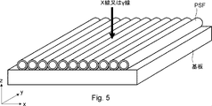
- FIG. 5 is a perspective view showing an application example of the plastic scintillation fiber according to the first embodiment.
- the plastic scintillation fiber PSF according to the first embodiment is arranged in an array on the substrate.
- the right-handed xyz orthogonal coordinates shown in FIG. 5 are for convenience in explaining the positional relationship of the components. Normally, the z-axis positive direction is vertically upward, and the xy plane is a horizontal plane.
- a photoelectric detector such as a photomultiplier tube is connected to each plastic scintillation fiber (PSF) (not shown), and the transmitted light can be detected.
- PSF plastic scintillation fiber
- one-dimensional image detection position detection
- the resolution is equal to the diameter of the plastic scintillation fiber PSF.
- PSF plastic scintillation fibers
- the image detection of X-rays and ⁇ -rays having high spatial resolution can be realized easily and at low cost by using the plastic scintillation fiber according to the present embodiment.
- Example 1 Add 20% by mass of lead methacrylate and 1% by mass of phosphor 2- (4-t-butylphenyl) -5- (4-biphenyl) -1,3,4-oxadiazole (b-PBD) to the styrene monomer. And copolymerized to form a cylinder for the outermost layer (first cylinder 11 in FIG. 4) having an outer diameter of 95 mm and an inner diameter of 71 mm.
- a core rod (rod 12 in FIG. 4) having a diameter of 65 mm made of polystyrene (refractive index 1.59) and a cylinder for a clad layer having an outer diameter of 70 mm and an inner diameter of 66 mm made of polymethylmethacrylate (refractive index 1.49).
- the second cylinder 13) of FIG. 4 was prepared.
- 2,5-Bis- (5-t-butyl-benzoxazoyl) thiophene (BBOT) as a wavelength conversion phosphor was dissolved in the core rod at a concentration of 200 mass ppm.
- the cylinder for the clad layer was inserted inside the cylinder for the outermost peripheral layer, and the rod for the core was inserted inside the cylinder for the clad layer to prepare a preform. While heating the tip of this preform, an integral wire was drawn so that the outer diameter was 1 mm under reduced pressure to obtain a plastic scintillation fiber according to Example 1.
- This plastic scintillation fiber has the cross-sectional configuration shown in FIG. The outer diameter was 1 mm, the diameter of the clad layer 3 was 0.72 mm, the diameter of the core 2 was 0.68 mm, the thickness of the outermost peripheral layer 1 was 0.14 mm, and the thickness of the clad layer 3 was 0.02 mm.
- FIG. 6 shows the emission spectra of the fluorophore 2- (4-t-butylphenyl) -5- (4-biphenyl) -1,3,4-oxadiazole (b-PBD) added to the outermost layer 1. It is a graph which shows the absorption and emission spectrum of the wavelength conversion phosphor BBOT. As shown in FIG. 6, the overlap between the emission spectrum of the outermost layer 1 and the absorption spectrum of the wavelength conversion phosphor is large.
- the plastic scintillation fiber according to the first embodiment is more than a conventional plastic scintillation fiber. Also improved the detection sensitivity to X-rays and ⁇ -rays.
- Example 2 In the same manner as in Example 1, a cylinder for the outermost peripheral layer (first cylinder 11 in FIG. 4) having an outer diameter of 95 mm and an inner diameter of 76 mm was molded. Further, as in Example 1, a core rod (rod 12 in FIG. 4) having a diameter of 65 mm made of polystyrene (refractive index 1.59) and an outer diameter 70 mm made of polymethylmethacrylate (refractive index 1.49). A cylinder for an inner clad layer having an inner diameter of 66 mm (second cylinder 13 in FIG. 4) was prepared. BBOT was dissolved in the core rod as a wavelength conversion phosphor at a concentration of 300 mass ppm.
- Example 2 a cylindrical body (not shown) for an outer clad layer having an outer diameter of 75 mm and an inner diameter of 71 mm made of a copolymer of a fluorinated monomer such as perfluoroalkyl acrylate (refractive index 1.42) was prepared.
- the cylinder for the outer clad layer constitutes the clad layer 4 shown in FIG. 3 after the line drawing process.
- a preform is produced by inserting the cylinder for the outer clad layer inside the cylinder for the outermost layer, inserting the cylinder for the inner clad layer inside the cylinder, and inserting the rod for the core inside the cylinder. bottom.
- This plastic scintillation fiber has the cross-sectional configuration shown in FIG.
- the outer diameter is 1 mm
- the outer diameter of the clad layer 4 is 0.76 mm
- the outer diameter of the clad layer 3 is 0.72 mm
- the diameter of the core 2 is 0.68 mm
- the thickness of the outermost peripheral layer 1 is 0.12 mm
- the clad layer 4 The thickness of the clad layer 3 was 0.02 mm
- the thickness of the clad layer 3 was 0.02 mm.
- Example 2 When X-rays were incident on the plastic scintillation fiber according to Example 2, a light amount about 30% higher than that of Example 1 could be observed at the tip 10 m away. Although the diameter of the core 2 was smaller than that of the first embodiment, it is considered that the total reflection angle was widened and the light emission was higher due to the provision of the clad layer 4 having a lower refraction.
- Example 3 Add 10% by mass of triphenylbismuth and 1% by mass of phosphor 2- (4-t-butylphenyl) -5 (4-biphenyl) -1,3,4-oxadiazole (b-PBD) to the styrene monomer. And polymerized, a cylinder for the outermost layer (first cylinder 11 in FIG. 4) having an outer diameter of 95 mm and an inner diameter of 71 mm was formed.
- a core rod (rod 12 in FIG. 4) having a diameter of 65 mm made of polystyrene (refractive index 1.59) and a cylinder for a clad layer having an outer diameter of 70 mm and an inner diameter of 66 mm made of polymethylmethacrylate (refractive index 1.49).
- the second cylinder 13) of FIG. 4 was prepared.
- 2,5-Bis- (5-t-butyl-benzoxazoyl) thiophene (BBOT) as a wavelength conversion phosphor was dissolved in the core rod at a concentration of 200 mass ppm.
- the cylinder for the clad layer was inserted inside the cylinder for the outermost peripheral layer, and the rod for the core was inserted inside the cylinder for the clad layer to prepare a preform. While heating the tip of this preform, an integral wire was drawn so that the outer diameter was 1 mm under reduced pressure to obtain a plastic scintillation fiber according to Example 3.
- This plastic scintillation fiber has the cross-sectional configuration shown in FIG. The outer diameter was 1 mm, the diameter of the clad layer 3 was 0.72 mm, the diameter of the core 2 was 0.68 mm, the thickness of the outermost peripheral layer 1 was 0.14 mm, and the thickness of the clad layer 3 was 0.02 mm.
- the plastic scintillation fiber according to the third embodiment is more than a conventional plastic scintillation fiber. Also improved the detection sensitivity to X-rays and ⁇ -rays.
- Example 4 An aluminum film was formed on the surface of the plastic scintillation fiber according to Example 1 by a thin-film deposition method to a thickness of about 50 nm. The scintillation light emitted by the outermost peripheral layer 1 and the light wavelength-converted by the core 2 are reflected by the reflection layer 5, so that the light is less likely to leak from the side surface of the fiber to the outside, resulting in high emission.
Landscapes
- Physics & Mathematics (AREA)
- Chemical & Material Sciences (AREA)
- General Physics & Mathematics (AREA)
- Engineering & Computer Science (AREA)
- Optics & Photonics (AREA)
- Health & Medical Sciences (AREA)
- Organic Chemistry (AREA)
- Materials Engineering (AREA)
- Inorganic Chemistry (AREA)
- Molecular Biology (AREA)
- High Energy & Nuclear Physics (AREA)
- Spectroscopy & Molecular Physics (AREA)
- Life Sciences & Earth Sciences (AREA)
- Mechanical Engineering (AREA)
- Ophthalmology & Optometry (AREA)
- Manufacturing & Machinery (AREA)
- Measurement Of Radiation (AREA)
Priority Applications (4)
| Application Number | Priority Date | Filing Date | Title |
|---|---|---|---|
| EP21879700.9A EP4231057A4 (en) | 2020-10-15 | 2021-07-01 | Plastic scintillating fiber and production method therefor |
| US18/032,065 US12270955B2 (en) | 2020-10-15 | 2021-07-01 | Plastic scintillating fiber and its manufacturing method |
| JP2022556401A JP7645899B2 (ja) | 2020-10-15 | 2021-07-01 | プラスチックシンチレーションファイバ及びその製造方法 |
| CN202180070610.7A CN116324514B (zh) | 2020-10-15 | 2021-07-01 | 塑料闪烁光纤及其制造方法 |
Applications Claiming Priority (2)
| Application Number | Priority Date | Filing Date | Title |
|---|---|---|---|
| JP2020-173826 | 2020-10-15 | ||
| JP2020173826 | 2020-10-15 |
Publications (1)
| Publication Number | Publication Date |
|---|---|
| WO2022079957A1 true WO2022079957A1 (ja) | 2022-04-21 |
Family
ID=81207908
Family Applications (1)
| Application Number | Title | Priority Date | Filing Date |
|---|---|---|---|
| PCT/JP2021/025035 Ceased WO2022079957A1 (ja) | 2020-10-15 | 2021-07-01 | プラスチックシンチレーションファイバ及びその製造方法 |
Country Status (5)
| Country | Link |
|---|---|
| US (1) | US12270955B2 (https=) |
| EP (1) | EP4231057A4 (https=) |
| JP (1) | JP7645899B2 (https=) |
| CN (1) | CN116324514B (https=) |
| WO (1) | WO2022079957A1 (https=) |
Families Citing this family (3)
| Publication number | Priority date | Publication date | Assignee | Title |
|---|---|---|---|---|
| WO2021085401A1 (ja) * | 2019-10-31 | 2021-05-06 | 株式会社クラレ | プラスチックシンチレーションファイバ及びその製造方法 |
| JP7645899B2 (ja) | 2020-10-15 | 2025-03-14 | 株式会社クラレ | プラスチックシンチレーションファイバ及びその製造方法 |
| EP4231056A4 (en) * | 2020-10-15 | 2024-11-06 | Kuraray Co., Ltd. | PLASTIC SCINTILLATING FIBER AND MANUFACTURING METHOD THEREFOR |
Citations (8)
| Publication number | Priority date | Publication date | Assignee | Title |
|---|---|---|---|---|
| US3041287A (en) * | 1959-01-27 | 1962-06-26 | Jr Mark Hyman | Heavy metal loaded plastic scintillating compositions |
| JPH06201835A (ja) * | 1992-12-28 | 1994-07-22 | Tohoku Electric Power Co Inc | 放射線検出光伝送装置 |
| JPH06317713A (ja) * | 1992-12-17 | 1994-11-15 | Nanoptics Inc | 高効率、高解像度、リアルタイムラジオグラフイメージング系 |
| JPH09236669A (ja) * | 1996-03-01 | 1997-09-09 | Tohoku Electric Power Co Inc | ファイバ型放射線検出器 |
| JP2011141239A (ja) | 2010-01-08 | 2011-07-21 | Japan Atomic Energy Agency | ピクセル型二次元イメージ検出器 |
| JP2015072227A (ja) | 2013-10-04 | 2015-04-16 | 独立行政法人日本原子力研究開発機構 | 中性子検出器 |
| JP2015513075A (ja) * | 2012-02-14 | 2015-04-30 | アメリカン サイエンス アンド エンジニアリング,インコーポレイテッドAmerican Science and Engineering,Inc. | 波長シフトファイバ結合シンチレーション検出器を用いるx線検査 |
| JP2020173826A (ja) | 2020-06-17 | 2020-10-22 | ソニー株式会社 | 情報処理装置、情報処理方法、および情報処理プログラム |
Family Cites Families (16)
| Publication number | Priority date | Publication date | Assignee | Title |
|---|---|---|---|---|
| US5308986A (en) | 1992-12-17 | 1994-05-03 | Nanoptics Incorporated | High efficiency, high resolution, real-time radiographic imaging system |
| DE19610538A1 (de) * | 1996-03-18 | 1997-09-25 | Deutsches Krebsforsch | Strahlungsermittlungsvorrichtung |
| JP2000065939A (ja) | 1998-08-18 | 2000-03-03 | Wired Japan:Kk | 光ファイバ及び光ファイバケーブル |
| JP2000137122A (ja) * | 1998-10-30 | 2000-05-16 | Nissei Denki Kk | プラスチックシンチレーションファイバ |
| DE69929027T2 (de) * | 1998-12-28 | 2006-08-24 | Kabushiki Kaisha Toshiba, Kawasaki | Strahlungsdetektoreinrichtung |
| JP4312365B2 (ja) * | 2000-10-11 | 2009-08-12 | 株式会社クラレ | 透明プラスチック線状体の製造方法 |
| JP4289913B2 (ja) | 2003-03-12 | 2009-07-01 | キヤノン株式会社 | 放射線検出装置及びその製造方法 |
| CN102183812A (zh) * | 2011-02-21 | 2011-09-14 | 北京大学 | 一种闪烁—移波光纤及快中子转换屏 |
| WO2015064588A1 (ja) | 2013-10-28 | 2015-05-07 | 株式会社トクヤマ | 中性子シンチレーター、中性子検出器及び中性子シンチレーターの製造方法 |
| US9482763B2 (en) * | 2014-05-08 | 2016-11-01 | Baker Hughes Incorporated | Neutron and gamma sensitive fiber scintillators |
| FR3030776B1 (fr) | 2014-12-22 | 2017-02-10 | Commissariat Energie Atomique | Scintillateur organique solide structure charge au plomb |
| JP6963547B2 (ja) * | 2016-06-21 | 2021-11-10 | 株式会社クラレ | プラスチックシンチレーションファイバ及びその製造方法 |
| JP6833611B2 (ja) * | 2017-05-25 | 2021-02-24 | 株式会社クラレ | プラスチック波長変換ファイバ及びその製造方法 |
| JP7048349B2 (ja) * | 2018-02-28 | 2022-04-05 | 株式会社クラレ | 高線量場プラスチックシンチレーションファイバー及びその製造方法 |
| EP4231056A4 (en) * | 2020-10-15 | 2024-11-06 | Kuraray Co., Ltd. | PLASTIC SCINTILLATING FIBER AND MANUFACTURING METHOD THEREFOR |
| JP7645899B2 (ja) | 2020-10-15 | 2025-03-14 | 株式会社クラレ | プラスチックシンチレーションファイバ及びその製造方法 |
-
2021
- 2021-07-01 JP JP2022556401A patent/JP7645899B2/ja active Active
- 2021-07-01 US US18/032,065 patent/US12270955B2/en active Active
- 2021-07-01 WO PCT/JP2021/025035 patent/WO2022079957A1/ja not_active Ceased
- 2021-07-01 CN CN202180070610.7A patent/CN116324514B/zh active Active
- 2021-07-01 EP EP21879700.9A patent/EP4231057A4/en active Pending
Patent Citations (8)
| Publication number | Priority date | Publication date | Assignee | Title |
|---|---|---|---|---|
| US3041287A (en) * | 1959-01-27 | 1962-06-26 | Jr Mark Hyman | Heavy metal loaded plastic scintillating compositions |
| JPH06317713A (ja) * | 1992-12-17 | 1994-11-15 | Nanoptics Inc | 高効率、高解像度、リアルタイムラジオグラフイメージング系 |
| JPH06201835A (ja) * | 1992-12-28 | 1994-07-22 | Tohoku Electric Power Co Inc | 放射線検出光伝送装置 |
| JPH09236669A (ja) * | 1996-03-01 | 1997-09-09 | Tohoku Electric Power Co Inc | ファイバ型放射線検出器 |
| JP2011141239A (ja) | 2010-01-08 | 2011-07-21 | Japan Atomic Energy Agency | ピクセル型二次元イメージ検出器 |
| JP2015513075A (ja) * | 2012-02-14 | 2015-04-30 | アメリカン サイエンス アンド エンジニアリング,インコーポレイテッドAmerican Science and Engineering,Inc. | 波長シフトファイバ結合シンチレーション検出器を用いるx線検査 |
| JP2015072227A (ja) | 2013-10-04 | 2015-04-16 | 独立行政法人日本原子力研究開発機構 | 中性子検出器 |
| JP2020173826A (ja) | 2020-06-17 | 2020-10-22 | ソニー株式会社 | 情報処理装置、情報処理方法、および情報処理プログラム |
Non-Patent Citations (4)
| Title |
|---|
| HAMEL MATTHIEU; BERTRAND GUILLAUME H. V.; CARREL FREDERICK; COULON ROMAIN; DUMAZERT JONATHAN; MONTBARBON EVA; SGUERRA FABIEN: "Plastic scintillators modifications for a selective radiation detection", 2015 4TH INTERNATIONAL CONFERENCE ON ADVANCEMENTS IN NUCLEAR INSTRUMENTATION MEASUREMENT METHODS AND THEIR APPLICATIONS (ANIMMA), IEEE, 20 April 2015 (2015-04-20), pages 1 - 6, XP032897850, DOI: 10.1109/ANIMMA.2015.7465496 * |
| JAPANESE JOURNAL OF APPLIED PHYSICS, vol. 54, 2015, pages 102202 |
| See also references of EP4231057A4 |
| TIBOR JACOB HAJAGOS, CHAO LIU, NERINE J. CHEREPY, QIBING PEI: "High-Z Sensitized Plastic Scintillators: A Review.", ADVANCED MATERIALS, vol. 30, no. 27, 5 July 2018 (2018-07-05), pages 1 - 13, XP055914014, DOI: 10.1002/adma.201706956 * |
Also Published As
| Publication number | Publication date |
|---|---|
| EP4231057A1 (en) | 2023-08-23 |
| JPWO2022079957A1 (https=) | 2022-04-21 |
| CN116324514A (zh) | 2023-06-23 |
| EP4231057A4 (en) | 2024-10-30 |
| CN116324514B (zh) | 2026-03-17 |
| US12270955B2 (en) | 2025-04-08 |
| US20230391030A1 (en) | 2023-12-07 |
| JP7645899B2 (ja) | 2025-03-14 |
Similar Documents
| Publication | Publication Date | Title |
|---|---|---|
| JP7629467B2 (ja) | プラスチックシンチレーションファイバ及びその製造方法 | |
| JP7645899B2 (ja) | プラスチックシンチレーションファイバ及びその製造方法 | |
| US9645257B2 (en) | Radiation sensor to detect different targeted radiation and radiation detection system including the radiation sensor | |
| JP6868643B2 (ja) | プラスチックシンチレーションファイバ及びその製造方法 | |
| JP6833611B2 (ja) | プラスチック波長変換ファイバ及びその製造方法 | |
| JP7048349B2 (ja) | 高線量場プラスチックシンチレーションファイバー及びその製造方法 | |
| JP6902549B2 (ja) | 高線量場プラスチックシンチレーションファイバー及びその製造方法 | |
| JP7645894B2 (ja) | プラスチックシンチレーションファイバ及びその製造方法 | |
| JP7394073B2 (ja) | 低透過性放射線検出プラスチックシンチレーションファイバ | |
| WO2021085401A1 (ja) | プラスチックシンチレーションファイバ及びその製造方法 | |
| JP7428714B2 (ja) | プラスチック波長変換ファイバ |
Legal Events
| Date | Code | Title | Description |
|---|---|---|---|
| 121 | Ep: the epo has been informed by wipo that ep was designated in this application |
Ref document number: 21879700 Country of ref document: EP Kind code of ref document: A1 |
|
| ENP | Entry into the national phase |
Ref document number: 2022556401 Country of ref document: JP Kind code of ref document: A |
|
| NENP | Non-entry into the national phase |
Ref country code: DE |
|
| ENP | Entry into the national phase |
Ref document number: 2021879700 Country of ref document: EP Effective date: 20230515 |
|
| WWG | Wipo information: grant in national office |
Ref document number: 18032065 Country of ref document: US |