WO2022079796A1 - 故障診断装置、学習装置、学習方法、および故障診断システム - Google Patents
故障診断装置、学習装置、学習方法、および故障診断システム Download PDFInfo
- Publication number
- WO2022079796A1 WO2022079796A1 PCT/JP2020/038607 JP2020038607W WO2022079796A1 WO 2022079796 A1 WO2022079796 A1 WO 2022079796A1 JP 2020038607 W JP2020038607 W JP 2020038607W WO 2022079796 A1 WO2022079796 A1 WO 2022079796A1
- Authority
- WO
- WIPO (PCT)
- Prior art keywords
- motor
- wear
- estimation
- unit
- bearing
- Prior art date
- Legal status (The legal status is an assumption and is not a legal conclusion. Google has not performed a legal analysis and makes no representation as to the accuracy of the status listed.)
- Ceased
Links
Images


Classifications
-
- G—PHYSICS
- G01—MEASURING; TESTING
- G01M—TESTING STATIC OR DYNAMIC BALANCE OF MACHINES OR STRUCTURES; TESTING OF STRUCTURES OR APPARATUS, NOT OTHERWISE PROVIDED FOR
- G01M13/00—Testing of machine parts
- G01M13/04—Bearings
-
- G—PHYSICS
- G01—MEASURING; TESTING
- G01N—INVESTIGATING OR ANALYSING MATERIALS BY DETERMINING THEIR CHEMICAL OR PHYSICAL PROPERTIES
- G01N3/00—Investigating strength properties of solid materials by application of mechanical stress
- G01N3/56—Investigating resistance to wear or abrasion
-
- H—ELECTRICITY
- H02—GENERATION; CONVERSION OR DISTRIBUTION OF ELECTRIC POWER
- H02P—CONTROL OR REGULATION OF ELECTRIC MOTORS, ELECTRIC GENERATORS OR DYNAMO-ELECTRIC CONVERTERS; CONTROLLING TRANSFORMERS, REACTORS OR CHOKE COILS
- H02P21/00—Arrangements or methods for the control of electric machines by vector control, e.g. by control of field orientation
- H02P21/14—Estimation or adaptation of machine parameters, e.g. flux, current or voltage
-
- H—ELECTRICITY
- H02—GENERATION; CONVERSION OR DISTRIBUTION OF ELECTRIC POWER
- H02P—CONTROL OR REGULATION OF ELECTRIC MOTORS, ELECTRIC GENERATORS OR DYNAMO-ELECTRIC CONVERTERS; CONTROLLING TRANSFORMERS, REACTORS OR CHOKE COILS
- H02P27/00—Arrangements or methods for the control of AC motors characterised by the kind of supply voltage
- H02P27/04—Arrangements or methods for the control of AC motors characterised by the kind of supply voltage using variable-frequency supply voltage, e.g. inverter or converter supply voltage
- H02P27/06—Arrangements or methods for the control of AC motors characterised by the kind of supply voltage using variable-frequency supply voltage, e.g. inverter or converter supply voltage using DC to AC converters or inverters
-
- H—ELECTRICITY
- H02—GENERATION; CONVERSION OR DISTRIBUTION OF ELECTRIC POWER
- H02P—CONTROL OR REGULATION OF ELECTRIC MOTORS, ELECTRIC GENERATORS OR DYNAMO-ELECTRIC CONVERTERS; CONTROLLING TRANSFORMERS, REACTORS OR CHOKE COILS
- H02P29/00—Arrangements for regulating or controlling electric motors, appropriate for both AC and DC motors
- H02P29/02—Providing protection against overload without automatic interruption of supply
- H02P29/024—Detecting a fault condition, e.g. short circuit, locked rotor, open circuit or loss of load
- H02P29/028—Detecting a fault condition, e.g. short circuit, locked rotor, open circuit or loss of load the motor continuing operation despite the fault condition, e.g. eliminating, compensating for or remedying the fault
-
- H—ELECTRICITY
- H02—GENERATION; CONVERSION OR DISTRIBUTION OF ELECTRIC POWER
- H02P—CONTROL OR REGULATION OF ELECTRIC MOTORS, ELECTRIC GENERATORS OR DYNAMO-ELECTRIC CONVERTERS; CONTROLLING TRANSFORMERS, REACTORS OR CHOKE COILS
- H02P6/00—Arrangements for controlling synchronous motors or other dynamo-electric motors using electronic commutation dependent on the rotor position; Electronic commutators therefor
- H02P6/14—Electronic commutators
- H02P6/16—Circuit arrangements for detecting position
- H02P6/18—Circuit arrangements for detecting position without separate position detecting elements
-
- H—ELECTRICITY
- H02—GENERATION; CONVERSION OR DISTRIBUTION OF ELECTRIC POWER
- H02P—CONTROL OR REGULATION OF ELECTRIC MOTORS, ELECTRIC GENERATORS OR DYNAMO-ELECTRIC CONVERTERS; CONTROLLING TRANSFORMERS, REACTORS OR CHOKE COILS
- H02P23/00—Arrangements or methods for the control of AC motors characterised by a control method other than vector control
- H02P23/0004—Control strategies in general, e.g. linear type, e.g. P, PI, PID, using robust control
- H02P23/0018—Control strategies in general, e.g. linear type, e.g. P, PI, PID, using robust control using neural networks
Definitions
- This disclosure relates to a failure diagnosis device, a learning device, a learning method, and a failure diagnosis system for diagnosing a failure of a motor.
- Patent Document 1 a plurality of state quantities of a diagnosis target machine are applied to a mathematical model showing a relationship between a plurality of deterioration degrees of a device, a plurality of state quantities, and a plurality of parameters indicating sensitivity for diagnosis.
- a failure diagnosis device that estimates a plurality of deterioration degrees of the target machine is described.
- Patent Document 1 does not describe in what driving state the motor estimates the degree of deterioration (wear amount), and temporarily determines the degree of deterioration of the bearing of the motor while the motor is being accelerated / decelerated.
- an error occurs in the estimated degree of deterioration due to the driving state of the motor, and the accuracy of failure diagnosis deteriorates.
- the failure diagnosis device erroneously diagnoses that the bearing of the motor is deteriorated, and there is a risk of causing downtime to stop the compressor for maintenance.
- This disclosure is made to solve the above-mentioned problems, and is a failure diagnosis device that can accurately estimate the failure of a motor so that unexpected downtime can be suppressed and appropriate maintenance measures can be taken. It is an object of the present invention to provide a learning device, a learning method, and a failure diagnosis system.
- the failure diagnosis device diagnoses a failure of the electric motor that drives the device.
- the failure diagnosis device includes a control unit that controls the drive of the motor, a wear estimation unit that estimates the wear information of the motor bearings based on the current flowing through the motor, and a wear estimation unit that estimates the wear information of the motor bearings. Based on this, it is provided with a failure notification unit that diagnoses a failure of the motor and notifies the user.
- the wear estimation unit estimates the wear information of the bearing of the motor
- the control unit controls the drive of the motor so that the motor is driven constantly.
- FIG. It is a block diagram for demonstrating an example of the structure of the failure diagnosis system in Embodiment 1.
- FIG. It is sectional drawing which shows an example of the internal structure of a compressor. It is sectional drawing of the spindle and the spindle of a compressor. It is a control block diagram of a control part. It is a flowchart for demonstrating an example of processing in a control part. It is a figure explaining the relationship between the operating state of a motor, and the current of a motor. It is a control block diagram which shows an example of the wear estimation part. It is a figure explaining an example of the display form of the exchange time of a compressor. It is a figure explaining an example of the notification timing of the diagnosis time.
- FIG. It is a control block diagram of the control part which concerns on Embodiment 2.
- FIG. It is a flowchart for demonstrating an example of the processing in the control part which concerns on Embodiment 2. It is a figure explaining the estimation error of the wear amount with respect to the speed of a motor.
- FIG. It is a figure for demonstrating the structural example of the learning part in Embodiment 3.
- FIG. This is an example of a flowchart of the learning process in the learning unit in the third embodiment.
- This is an example of a flowchart of the estimation process in the estimation unit in the fourth embodiment.
- the forms of the components shown in all the embodiments described below are merely examples, and are not limited to the forms described below.
- the combination of components is not limited to the combination in each embodiment, and the components described in other embodiments can be applied to other embodiments.
- the high and low of parameters such as pressure and temperature, the high and low are not determined in relation to the absolute value, but are relatively determined by the state and operation of the device and the like.
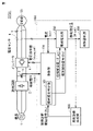
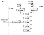
- FIG. 1 is a block diagram for explaining an example of the configuration of the failure diagnosis system SYS1 according to the first embodiment.
- the failure diagnosis system SYS1 shown in FIG. 1 includes a compressor 50 including an electric motor (not shown) which is a target of failure diagnosis, and a failure diagnosis device 1000 for diagnosing a failure of the electric motor.
- the configuration for driving the compressor 50 includes an AC power supply 1, a rectifier circuit 2, an electrolytic capacitor 3, and an inverter 4.
- the rectifier circuit 2 converts the three-phase (UVW phase) AC power from the AC power supply 1 into DC power.
- the electrolytic capacitor 3 smoothes the DC power from the rectifier circuit 2.
- the inverter 4 converts the DC power from the rectifier circuit 2 into three-phase AC power, and outputs the three-phase AC power to the compressor 50.
- the voltage sensor 5 detects the bus voltage Vdc applied to the electrolytic capacitor 3.
- the current sensor 6 is provided in the middle of the wiring 7 from the inverter 4 to the compressor 50, and detects two-phase currents (for example, current Iu and current Iv) in the three-phase AC flowing from the inverter 4 to the compressor 50. do.
- the configuration for driving the compressor 50 includes a control unit 100 for controlling the drive of the compressor 50.
- the control unit 100 outputs a voltage command value (Vuvw_ref) to the inverter 4 based on the results detected by the voltage sensor 5 and the current sensor 6, and drives the compressor 50 by PWM (Pulse Width Modulation) control.
- the control unit 100 not only controls the drive of the compressor 50, but also functions as a part of the configuration of the failure diagnosis device 1000.
- the failure diagnosis device 1000 includes a control unit 100, a wear estimation unit 200, a failure notification unit 300, and a wear diagnosis generation unit 400.
- the failure diagnosis device 1000 can be realized by hardware such as a computer that executes various programs, and the arithmetic unit that executes various processes includes, for example, a CPU (Central Processing Unit) and an FPGA (Field-Programmable Gate). Array) etc. are used.
- a CPU Central Processing Unit
- FPGA Field-Programmable Gate
- the control unit 100 has a wear estimation determination device 101. Further, the control unit 100 is a wear estimation unit based on the failure diagnosis start signal Fs from the wear diagnosis generation unit 400, the bus voltage Vdc from the voltage sensor 5, and the two-phase current Iuv in the three-phase alternating current.
- the estimation start signal Es and the phase estimation value ⁇ _est are output to 200.
- the phase estimated value ⁇ _est is a value estimated by the control unit 100 based on the currents of two phases of the three-phase alternating current detected by the current sensor 6.
- the wear estimation unit 200 estimates the degree of deterioration (wear amount) of the bearing of the motor that drives the compressor 50 from the currents of the two phases of the three-phase alternating current, the estimation start signal Es, and the phase estimation value ⁇ _est. ..
- the wear amount of the bearing of the motor will be described below, but the present invention is not limited to this.
- the wear estimation unit 200 sets the estimated wear amount as the wear estimation amount W_est and outputs the estimated wear amount to the failure notification unit 300 and the wear diagnosis generation unit 400.
- the amount of wear of the bearing of the motor is one of the wear information.
- the degree of deterioration is not limited to the three-phase alternating current, and three of the three-phase alternating currents are used.
- a phase or one-phase current may be used to estimate the degree of deterioration of the motor bearings.
- the failure notification unit 300 notifies the replacement time of the compressor 50 according to the wear estimation amount W_est estimated by the wear estimation unit 200.
- the wear diagnosis generation unit 400 outputs a failure diagnosis start signal Fs for starting the wear estimation of the bearing of the motor to the wear estimation determination device 101 of the control unit 100 according to the wear estimation amount W_est estimated by the wear estimation unit 200.
- FIG. 2 is a cross-sectional view showing an example of the internal structure of the compressor 50.
- the compressor 50 shown in FIG. 2 includes a suction pipe 51, a spindle 52, an electric motor 53, a lubricating oil 54, an oil pump 55, an auxiliary bearing 56, a main bearing 57, a compression mechanism 58, and a discharge pipe 59. including.
- the compressor 50 constitutes a part of the air conditioning equipment and forms a refrigerating cycle for compressing the refrigerant flowing through the pipe. Further, the refrigerant is sucked from the suction pipe 51 of the compressor 50 and discharged from the discharge pipe 59.
- the suction pipe 51 is a pipe for sucking a low-temperature and low-pressure refrigerant into the compressor 50.
- a pressure sensor, a temperature sensor, a humidity sensor, or the like may be attached to the suction pipe 51 to measure the pressure, temperature, humidity, and the like of the refrigerant flowing in the pipe. Further, these sensors may be attached to the pipes in the air conditioner to estimate the pressure, temperature, humidity and the like of the refrigerant flowing in the suction pipe 51.
- the motor 53 is connected to a three-phase alternating current power line and is driven according to the voltage applied from the inverter 4.
- the spindle 52 is connected to the motor 53 and transmits rotational energy to the compression mechanism 58.
- the lubricating oil 54 is accumulated in the bottom of the compressor 50 and is supplied to the auxiliary bearing 56 and the main shaft 52 by the oil pump 55 to lubricate the auxiliary bearing 56 and the main shaft 52.
- a liquid level sensor capable of detecting the height of the oil level of the lubricating oil 54 may be attached to measure the amount of the lubricating oil 54.
- the discharge pipe 59 is a pipe for discharging the high-temperature and high-pressure refrigerant compressed by the compression mechanism 58 to the outside of the compressor 50.
- a pressure sensor, a temperature sensor, a humidity sensor, or the like may be attached to the discharge pipe 59 to measure the pressure, temperature, humidity, and the like of the refrigerant flowing in the pipe. Further, these sensors may be attached to the pipes in the air conditioner to estimate the pressure, temperature, humidity and the like of the refrigerant flowing in the discharge pipe 59.
- FIG. 3 is a cross-sectional view of the main shaft 52 and the main bearing 57 of the compressor 50. Note that FIG. 3A shows a cross-sectional view of the main shaft 52 and the main bearing 57 in a lubricated state during normal driving, and FIG. 3B shows a cross-sectional view of the main shaft 52 and the main bearing 57 in a lubricated state. Instead, a cross-sectional view of the abnormal drive is shown. As shown in FIG.
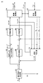
- FIG. 4 is a control block diagram of the control unit 100.
- the control unit 100 includes a wear estimation determination device 101, an excitation current command generator 102, a PI (proportional integral) controller 103, a coordinate converter 104, a PI controller 105, a PI controller 106, and coordinate conversion.
- the device 107 and the speed estimator 108 are included.
- the wear estimation determination device 101 receives the failure diagnosis start signal Fs from the wear diagnosis generation unit 400, outputs the estimation start signal Es to the wear estimation unit 200, and generates the speed command value ⁇ _ref.
- the excitation current command generator 102 generates an excitation current command value Id_ref according to the velocity command value ⁇ _ref.
- the PI controller 103 performs proportional integral control based on the difference value between the excitation current command value Id_ref and the d-axis current Id converted by the coordinate converter 107 to calculate the d-axis voltage command value Vd_ref, and calculates the d-axis voltage command value Vd_ref.
- the command value Vd_ref is output to the coordinate converter 104.
- the coordinate converter 104 coordinates the d-axis voltage command value Vd_ref from the PI controller 103 and the q-axis voltage command value Vq_ref from the PI controller 106 based on the phase estimation value ⁇ _est estimated by the speed estimator 108.
- the conversion process is performed, the voltage command value Vuvw_ref of the three-phase AC is calculated, and the voltage command value Vuvw_ref is output to the inverter 4.
- the PI controller 105 performs proportional integral control based on the difference value between the speed command value ⁇ _ref and the speed estimated value ⁇ _est estimated by the speed estimator 108 to calculate the q-axis current command value Iq_ref, and the q-axis current command.
- the value Iq_ref is output to the PI controller 106.
- the PI controller 106 performs proportional integral control based on the difference value between the q-axis current command value Iq_ref and the q-axis current Iq converted by the coordinate converter 107 to calculate the q-axis voltage command value Vq_ref, and calculates the q-axis voltage command value Vq_ref.
- the voltage command value Vq_ref is output to the coordinate converter 104.
- the velocity estimator 108 estimates the velocity estimation value ⁇ _est and the phase estimation value ⁇ _est based on the d-axis voltage command value Vd_ref, the q-axis voltage command value Vq_ref, and the d-axis current Id and the q-axis current Iq. Then, the estimated speed estimation value ⁇ _est is output to the PI controller 105, and the estimated phase estimation value ⁇ _est is output to the coordinate converter 104, the coordinate converter 107, and the wear estimation unit 200.
- the velocity estimator 108 estimates the velocity estimation value ⁇ _est and the phase estimation value ⁇ _est by applying, for example, an adaptive magnetic flux observer which is a known technique.
- the applied magnetic flux observer is excellent in that it has robustness against fluctuations in the number of interlinkage magnetic fluxes and does not cause an error in steady velocity estimation. For this reason, the adaptive flux observer is widely recognized as a high-performance velocity estimation method.
- the velocity estimator 108 is not limited to the configuration in which the velocity is estimated by using the adaptive magnetic flux observer.
- the control unit 100 estimates the speed of the electric motor 53 that drives the compressor 50, and controls the speed of the electric motor 53 so as to follow the speed command value ⁇ _ref generated by the wear estimation determination device 101. Can be done.
- FIG. 5 is a flowchart for explaining an example of processing in the control unit 100.
- FIG. 5 describes a control flow of the wear estimation determination device 101.
- the wear estimation determination device 101 determines whether or not the failure diagnosis start signal Fs from the wear diagnosis generation unit 400 is an “ON” signal (step S101).
- the wear estimation determination device 101 determines that the failure diagnosis is to be started, and generates a command value so that the speed command value ⁇ _ref becomes a constant value. Then, the speed command value ⁇ _ref is output to the exciting current command generator 102 and the PI controller 105 (step S102).
- the wear estimation determination device 101 generates the speed command value ⁇ _ref, and then outputs the estimation start signal Es of the “ON” signal to the wear estimation unit 200 (step S103).
- the wear estimation unit 200 performs a process of estimating the amount of wear of the main bearing 57 by receiving the estimation start signal Es.
- the wear estimation determination device 101 determines that the compressor 50 is normally operated (step S104). In the case of normal operation, the wear estimation determination device 101 generates a speed command value ⁇ _ref according to the load state of the compressor 50, and outputs the speed command value ⁇ _ref to the exciting current command generator 102 and the PI controller 105. .. For example, the wear estimation determination device 101 generates a high speed command value ⁇ _ref when the load state of the compressor 50 is high, and generates a low speed command value ⁇ _ref when the load state of the compressor 50 is low, and the load state.
- the wear estimation determination device 101 generates a speed command value ⁇ _ref that drives the motor 53 constantly in order to start the failure diagnosis when the failure diagnosis start signal Fs is an “ON” signal. , "OFF" signal, the speed command value ⁇ _ref corresponding to the load state of the compressor 50 is generated for normal operation.
- FIG. 6 is a diagram illustrating the relationship between the operating state of the motor 53 and the current of the motor 53.
- FIG. 6A illustrates changes in the speed command value and the current value while the motor 53 is being accelerated and driven.
- the horizontal axis is the elapsed time (sec) and the vertical axis is the speed command value (rad / sec).
- the horizontal axis is the elapsed time (note that the scale is different from the elapsed time in the upper graph)
- the vertical axis is the current value of the U phase of the motor 53.
- FIG. 6B illustrates changes in the speed command value and the current value while the motor 53 is being driven constantly.
- the horizontal axis is the elapsed time (sec) and the vertical axis is the speed command value (rad / sec).
- the horizontal axis is the elapsed time (note that the scale is different from the elapsed time in the upper graph), and the vertical axis is the current value of the U phase of the motor 53.
- the period Ta, the period Tb, and the period Tc shown in FIG. 6 represent one cycle of the current of the motor 53 at a certain time point.
- the speed command value ⁇ _ref increases with the passage of time, and the amplitude of the current of the electric motor 53 gradually increases.
- the speed command value ⁇ _ref increases, the length of one cycle of the current of the motor 53 gradually shortens (Ta> Tb).
- the speed command value ⁇ _ref becomes lower with the passage of time, and the amplitude of the current of the motor 53 gradually becomes smaller.
- the speed command value ⁇ _ref decreases, the length of one cycle of the current of the motor 53 gradually increases (Ta ⁇ Tb).
- the speed command value ⁇ _ref becomes constant, and the amplitude of the current of the motor 53 also becomes constant. Further, when the speed command value ⁇ _ref is constant, the length of one cycle of the current of the motor 53 is also constant (Tc). Therefore, when the motor 53 of the compressor 50 is constantly driven, the fluctuation of the current of the motor 53 is smaller than that of the case where the motor 53 is being driven for acceleration / deceleration, and the condition is that the amount of wear of the main bearing 57 is estimated.
- the constant drive is preferably a state in which the rotation speed of the electric motor 53 is driven within ⁇ 1% of the target rotation speed. If the rotation speed is in this section, the accuracy of estimating the friction information can be improved. It is desirable that the rotation speed is substantially the same and does not change because the accuracy of estimating the friction information is further improved.
- FIG. 7 is a control block diagram showing an example of the wear estimation unit 200.
- the wear estimation unit 200 includes a three-phase converter 201, a phase converter 202, a coordinate converter 203, a low-pass filters 204 and 205, an absolute value calculator 206, and a switch 207.
- the three-phase converter 201 calculates the W-phase current Iw from the two-phase currents (Iu, Iv) using Equation 1, and outputs the three-phase alternating current Iuvw to the coordinate converter 203.
- the phase converter 202 the phase estimated value ⁇ _est from the speed estimator 108 is inverted, and the inverted phase estimated value ⁇ _est is calculated.
- the coordinate converter 203 performs coordinate conversion processing on the three-phase alternating current Iuvw using the phase estimation value ⁇ _est inverted by the phase converter 202, and the two-axis DC component orthogonal to the three-phase alternating current Iuvw. Convert to.
- the low-pass filters 204 and 205 remove the AC component from the two-axis DC component converted by the coordinate converter 203, and extract only the necessary DC component.
- the absolute value calculator 206 the absolute value of the DC component of the two axes, that is, the square root value of the sum of squares is obtained to obtain the reverse phase current value. Further, the absolute value calculator 206 calculates the wear estimation amount W_est1 according to the reverse phase current value, and outputs the wear estimation amount W_est1 to the switch 207.
- the coordinate converter 203 and the low-pass filters 204 and 205 are band-pass filters specialized for the current component that rotates in the opposite direction, have the effect of extracting the DC component, and function as a simple and high-performance filter. ing.
- the switch 207 switches whether or not to output the wear estimation amount W_est1 according to the estimation start signal Es. Specifically, when the estimation start signal Es is an "ON" signal, the switch 207 outputs the wear estimator W_est1 output from the absolute value calculator 206, and the estimation start signal Es is an "OFF" signal. In this case, the previous wear estimation amount W_est is output as the wear estimation amount W_est2.
- FIG. 8 is a diagram illustrating an example of a display form of the replacement time of the compressor 50.
- the failure notification unit 300 notifies the user of the period until the failure according to the value of the wear estimation amount W_est based on the reference shown in FIG. 8 (a).
- the wear estimation amount W_est is large, the display period of the failure notification unit 300 is set to be short. For example, if the wear estimation amount is 0 " ⁇ m", the failure notification unit 300 sets "12 months” as the display period. If the estimated wear amount is less than 20 “ ⁇ m”, the failure notification unit 300 sets "10 months” as the display period. If the estimated wear amount is less than 40 " ⁇ m”, the failure notification unit 300 sets "8 months” as the display period.
- the failure notification unit 300 sets "6 months” as the display period. If the estimated wear amount is less than 80 " ⁇ m”, the failure notification unit 300 sets "4 months” as the display period. If the estimated wear amount is less than 100 " ⁇ m”, the failure notification unit 300 sets "2 months” as the display period. Further, according to the display period set in FIG. 8A, for example, the failure notification unit 300 should replace the compressor within ⁇ as shown in FIG. 8B. Is displayed on the display (not shown) to urge the user to replace the compressor 50.
- ⁇ means the display period.
- the target for which the failure notification unit 300 prompts the user to replace is not limited to the compressor 50, but may be the electric motor 53 or the main bearing 57 of the electric motor 53.
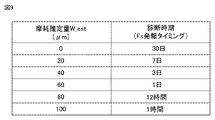
- FIG. 9 is a diagram illustrating an example of the notification timing of the diagnosis time.
- the wear diagnosis generation unit 400 performs failure diagnosis at a diagnosis time according to the value of the wear estimation amount W_est based on the reference shown in FIG.
- the wear diagnosis generation unit 400 issues a failure diagnosis start signal Fs to the control unit 100 for each diagnosis period shown in FIG.
- the wear diagnosis generation unit 400 is set so that the diagnosis period is shortened if the wear estimation amount W_est is large. For example, if the wear estimation amount is 0 “ ⁇ m”, the wear diagnosis generation unit 400 issues a failure diagnosis start signal Fs at intervals of “30 days”. Further, if the wear estimation amount is less than 20 " ⁇ m", the wear diagnosis generation unit 400 issues a failure diagnosis start signal Fs at intervals of "7 days".
- the wear diagnosis generation unit 400 issues a failure diagnosis start signal Fs at intervals of "3 days”. Further, if the wear estimation amount is less than 60 “ ⁇ m”, the wear diagnosis generation unit 400 issues a failure diagnosis start signal Fs at intervals of "1 day”. Further, if the wear estimation amount is less than 80 " ⁇ m”, the wear diagnosis generation unit 400 issues a failure diagnosis start signal Fs at intervals of "12 hours”. Further, if the wear estimation amount is less than 100 " ⁇ m”, the wear diagnosis generation unit 400 issues a failure diagnosis start signal Fs at intervals of "1 hour”.
- the fact that the wear diagnosis generation unit 400 issues the failure diagnosis start signal Fs means that the failure diagnosis start signal Fs of the "ON" signal is output, and other than that, the failure of the "OFF” signal.
- the diagnosis start signal Fs is output.
- the wear diagnosis generation unit 400 sets the diagnosis time in a period shorter than the period in which the failure notification unit 300 displays a display prompting the user to replace the compressor 50. That is, the wear diagnosis generation unit 400 generates a signal indicating the start of the failure diagnosis in a period shorter than the period in which the failure notification unit 300 notifies the user of information based on the wear information (for example, information prompting the replacement of the compressor 50). do.
- the failure diagnosis device 1000 diagnoses the failure of the electric motor that drives the device.
- the failure diagnosis device 1000 is estimated by the control unit 100 that controls the drive of the motor 53, the wear estimation unit 200 that estimates the wear amount of the bearing of the motor 53 based on the current flowing through the motor 53, and the wear estimation unit 200.
- a failure notification unit 300 for diagnosing a failure of the motor 53 and notifying the user based on the amount of wear of the bearing of the motor 53 is provided.
- the control unit 100 controls the drive of the motor 53 so that the motor 53 is driven constantly.
- the failure diagnosis device 1000 estimates the amount of wear of the bearing while the motor 53 is in constant drive, so that the amount of wear can be estimated more accurately than when the motor 53 is in acceleration / deceleration drive, and unexpected downtime is suppressed. Appropriate maintenance measures can be taken.
- control unit 100 may control the motor 53 by driving the rotation speed to be constant (for example, generate a command value so that the speed command value ⁇ _ref becomes a constant value).
- control unit 100 can control the electric motor 53 by driving the rotation speed to be constant, and cause the wear estimation unit 200 to estimate the amount of wear of the bearing while the electric motor 53 is constantly driven.
- a wear diagnosis generation unit 400 that generates a signal indicating the start of failure diagnosis to the control unit 100 based on the wear amount estimated by the wear estimation unit 200.
- the control unit 100 can control the start of the failure diagnosis based on the signal indicating the start of the failure diagnosis (fault diagnosis start signal Fs).
- the wear diagnosis generation unit 400 generates a signal indicating the start of the failure diagnosis in a shorter period than the period in which the failure notification unit 300 notifies the user of the information based on the wear information.
- the failure notification unit 300 notifies the user of the replacement time of the bearing of the motor 53 based on the wear amount of the bearing of the motor 53 estimated by the wear estimation unit 200.
- the failure notification unit 300 can appropriately urge the user to replace the bearing of the motor 53 or the motor 53, and can make the user aware of the timing of performing maintenance in advance, which is appropriate. Maintenance measures can be taken.
- the failure diagnosis system SYS1 controls the driving of the electric motor 53 by outputting a voltage command to the electric motor 53 for driving the equipment, the inverter 4 for supplying power to the electric motor 53, and the inverter 4.
- the motor 53 is based on the wear estimation unit 200 that estimates the wear amount of the bearing of the motor 53 based on the control unit 100 and the current flowing through the motor 53, and the wear amount of the bearing of the motor 53 estimated by the wear estimation unit 200. It is provided with a failure notification unit 300 that diagnoses the failure and notifies the user of the failure.
- the wear estimation unit 200 estimates the amount of wear of the bearing of the motor 53
- the control unit 100 controls the drive of the motor 53 so that the motor 53 is driven constantly.
- the failure diagnosis system SYS1 estimates the amount of wear of the bearing while the motor 53 is in constant drive, so that the amount of wear can be estimated more accurately than when the motor 53 is in acceleration / deceleration drive, and unexpected downtime is suppressed. Appropriate maintenance measures can be taken.
- Embodiment 2 In the failure diagnosis device 1000 of the first embodiment, a configuration is described in which control is performed to drive the electric motor 53 constantly and the amount of wear of the bearing of the electric motor 53 is estimated while the electric motor 53 is constantly driven.
- FIG. 10 is a control block diagram of the control unit 100 according to the second embodiment.
- the input / output information of the wear estimation determination device 109 is different from that of the first embodiment.
- the other configurations of the failure diagnosis system according to the second embodiment are the same as the configurations of the first embodiment, and the same configurations are designated by the same reference numerals and detailed description thereof will not be repeated.
- the wear estimation determination device 109 has a failure diagnosis start signal Fs, a bus voltage Vdc from the voltage sensor 5, a d-axis voltage command value Vd_ref from the PI controller 103, and the PI controller 106.
- the q-axis voltage command value Vq_ref of is input. That is, the wear estimation determination device 109 generates the estimation start signal Es and the speed command value ⁇ _ref in consideration of the bus voltage Vdc, the d-axis voltage command value Vd_ref, and the q-axis voltage command value Vq_ref.
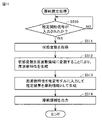
- FIG. 11 is a flowchart for explaining an example of processing in the control unit 100 according to the second embodiment.
- FIG. 11 describes a control flow of the wear estimation determination device 109.
- the wear estimation determination device 109 determines whether or not the failure diagnosis start signal Fs from the wear diagnosis generation unit 400 is an “ON” signal (step S101).
- the wear estimation determiner 109 calculates the modulation factor based on the bus voltage Vdc, the d-axis voltage command value Vd_ref, and the q-axis voltage command value Vq_ref. (Step S105). Specifically, the wear estimation determination device 109 calculates the modulation factor Duty using the following (Equation 2).
- the wear estimation determination device 109 determines whether or not the calculated modulation factor Duty is equal to or greater than the preset value A and less than the preset value B (step S106).
- the wear estimation determiner 109 determines that the failure diagnosis is to be started, and the speed command value ⁇ _ref is set.
- a command value is generated so as to be a constant value, and the speed command value ⁇ _ref is output to the exciting current command generator 102 and the PI controller 105 (step S102).
- the wear estimation determination device 109 generates the speed command value ⁇ _ref and then outputs the estimation start signal Es of the “ON” signal to the wear estimation unit 200 (step S103).
- the wear estimation unit 200 performs a process of estimating the amount of wear of the main bearing 57 by receiving the estimation start signal Es.
- step S101 when the failure diagnosis start signal Fs is an "OFF" signal (NO in step S101), or when the calculated modulation factor Wear is less than the preset value A or greater than or equal to the preset value B (in step S106). NO), the wear estimation determination device 109 determines that the compressor 50 is normally operated (step S104).
- the preset value A may be set to a value less than 1 at which voltage saturation occurs, and is set to 0.9 in consideration of load fluctuation of the compressor 50, for example. Further, the preset value B is set to less than 1 at which voltage saturation does not occur.
- FIG. 12 is a diagram illustrating an error in estimating the amount of wear with respect to the speed of the motor 53.
- the horizontal axis shown in FIG. 12 represents the speed (rotational speed) of the motor 53, and the vertical axis represents the wear estimation error of the main bearing 57.
- the wear estimation error is the difference between the absolute values of the wear estimation amount W_est and the actual wear amount.
- the actual amount of wear is the amount of wear when the bearing is shaved to a predetermined value in advance to reproduce the wear.
- the wear estimation error is large at the speed of the motor 53, it is not suitable for the period for estimating the wear amount, and conversely, if the wear estimation error is small, it is suitable for estimating the wear amount. It is a period.
- the speed of the motor 53 is low (region of modulation factor ⁇ 1), the speed estimation error is easily affected in the speed estimator 108, so that an error occurs in the phase estimation value ⁇ _est. Therefore, the wear estimation error becomes large, and a modulation factor smaller than the preset value A is not suitable for the period for estimating the wear amount.
- the wear estimation determination device 109 generates a command value so that the speed command value ⁇ _ref becomes a constant value in the range where the modulation factor is equal to or higher than the preset value A and less than the preset value B, thereby causing wear. Since the wear estimation error in the estimation unit 200 becomes small, it can be determined that it is suitable for the period for estimating the wear amount.
- step S101 to step S104 are the same as the contents described in the first embodiment.
- the failure diagnosis device 1000 determines whether or not the control unit 100 controls to drive the electric motor 53 constantly based on the calculated modulation factor. As a result, the failure diagnosis device 1000 can determine the speed command value of the electric motor 53 according to the modulation factor and estimate the wear amount. Therefore, the wear amount is estimated in consideration of the influence of the load fluctuation of the compressor 50. Can be carried out accurately. Further, in the second embodiment, unexpected downtime can be suppressed and appropriate maintenance measures can be taken.
- the control unit 100 preferably controls to drive the motor constantly. As a result, the control unit 100 determines the speed command value when the modulation factor is in the vicinity of 1, and estimates the wear amount. Therefore, the accuracy of estimating the wear amount deteriorates due to the phase estimation error in the low speed range, and the voltage in the high speed range. It is possible to suppress deterioration of the estimation accuracy of the amount of wear due to saturation.
- Embodiment 3 In the failure diagnosis device 1000 according to the third embodiment, a configuration for estimating wear information (wear amount) of the bearing of the motor 53 by using so-called artificial intelligence (AI) will be described.
- AI artificial intelligence
- the learning process will be described first, prior to the explanation of estimating the wear information of the main bearing 57 of the electric motor 53.
- This learning process is a process for generating an estimation model used for estimating wear information of a bearing of a motor.
- the process of estimating the wear information of the bearing of the motor using the estimation model generated in the third embodiment will be described.
- FIG. 13 is a block diagram for explaining an example of the configuration of the failure diagnosis system SYS2 in the third embodiment.
- the failure diagnosis system SYS2 in the third embodiment has the same configuration as the failure diagnosis system SYS1 in the first embodiment except that the wear estimation unit 200 is different from the wear estimation unit 500, and the same configuration has the same reference numeral. Do not repeat the detailed explanation.
- the wear estimation unit 500 differs from the wear estimation unit 200 in input / output information and internal processing.
- the wear estimation unit 500 includes an estimation start signal Es from the control unit 100, two-phase currents (for example, Iu and Iv) in the three-phase AC detected by the current sensor 6, and the pressure of the refrigerant in the compressor 50.
- the state quantity including the temperature around the compressor 50, the humidity around the compressor 50, and the flow rate of the refrigerant is acquired.
- the "refrigerant pressure in the compressor 50" is referred to as “refrigerant pressure”.
- the "temperature around the compressor 50" is called “temperature”.
- Humidity around the compressor 50” is called “humidity”.
- the "refrigerant flow rate” is called “refrigerant flow rate”.
- Refrigerant pressure, temperature, humidity, and refrigerant flow rate are state quantities indicating the operating state of the air conditioner. Then, the wear estimation unit 500 sets the wear estimation amount W_est estimated by artificial intelligence based on the current of two phases in the three-phase AC detected by the current sensor 6 and the state amount indicating the operating state to the failure notification unit 300. And output to the wear diagnosis generation unit 400.
- the wear estimation unit 500 includes a learning unit 500A and an estimation unit 500B. First, the learning unit 500A will be described.
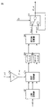
- FIG. 14 is a diagram for explaining a configuration example of the learning unit 500A in the third embodiment.
- the learning unit 500A includes a first measuring device 501, a second measuring device 502, a wear determining device 503, an observing device 504, a converter 505, an acquirer 506, an extractor 507, and a learning device 508. Have.
- the first measuring instrument 501 measures the current (Iuv) of two phases of the three-phase alternating current detected by the current sensor 6.
- the first measuring instrument 501 outputs the detected current to the observer 504 as time series data. Further, the current detected by the current sensor 6 is also referred to as a "first state variable".
- the second measuring instrument 502 outputs the refrigerant pressure, temperature, humidity, and refrigerant flow rate to the observer 504 as time series data.
- Refrigerant pressure, temperature, humidity, and refrigerant flow rate are also referred to as "second state variables" or “variables indicating the operating state of air conditioning equipment”.
- the second state variable is not limited to including all information on refrigerant pressure, temperature, humidity, and refrigerant flow rate, and even if it is at least one piece of information on refrigerant pressure, temperature, humidity, and refrigerant flow rate, the refrigerant pressure,
- the temperature, humidity, and refrigerant flow information may include additional information (eg, operating noise around the compressor 50).
- the first state variable and the second state variable are collectively referred to as a "state variable".
- the "state variable” may be expressed as a "parameter” or a "feature amount”.
- the observer 504 acquires each state variable from these time-series data by observing the time-series data from the first measuring instrument 501 and the second measuring instrument 502.
- Each state variable acquired by the observer 504 is input to the converter 505.
- the converter 505 converts each of the acquired state variables into a frequency domain.
- the converter 505 transforms each of the acquired state variables into a frequency domain, for example, by Fourier transform or fast Fourier transform.
- the converter 505 may convert each of the acquired state variables into a frequency domain by another method.
- the frequency characteristics of each state variable converted into the frequency domain by the converter 505 are output to the acquirer 506.
- the wear determination device 503 determines the wear of the main bearing 57 of the electric motor 53 by using, for example, a predetermined method.
- the wear determination device 503 generates wear information independently of the wear information estimated by the estimation unit 500B described in the fourth embodiment.
- the wear information includes at least information on the amount of wear of the main bearing 57 of the motor 53, and may include other information such as the presence or absence of wear of the main bearing 57 of the motor 53. Further, the wear determining device 503 determines whether or not to estimate the wear information based on the estimation start signal Es.
- the wear determining device 503 reproduces the wear state of the main bearing 57 of the electric motor 53 in a simulation environment simulating the estimation unit 500B described in the fourth embodiment, and outputs wear information in response to the wear state. You may estimate.
- the wear information generated by the wear determination device 503 is input to the acquirer 506.
- the acquirer 506 acquires a learning data set including a plurality of learning data in which bearing wear information is labeled with the frequency characteristics of each state variable of the motor 53.
- the acquirer 506 acquires, for example, the frequency characteristics of each state variable converted by the converter 505 in association with the wear information generated by the wear determiner 503 as a learning data set.
- the extractor 507 also extracts frequency characteristics from the learning data set.
- the learner 508 inputs the frequency characteristics extracted from the training data set into the estimation model so that the estimation result output from the estimation model approaches the wear information labeled in the training data set. , Optimize the parameters of the estimation model.
- the estimation model includes, for example, a neural network and the parameters used by the neural network.
- FIG. 15 is an example of a flowchart of the learning process in the learning unit 500A in the third embodiment.
- the learning unit 500A determines in the wear determination device 503 to determine the start of estimation of wear information based on whether or not the estimation start signal Es from the wear estimation determination device 101 is an “ON” signal (step S501). When the estimation start signal Es is an "OFF" signal (NO in step S501), the learning unit 500A returns the process to step S501.
- the learning unit 500A when the estimation start signal Es is an "ON" signal (YES in step S501), the learning unit 500A generates wear information in the wear determination device 503 and acquires the generated wear information in the acquirer 506 (YES in step S501). Step S502).
- the learning unit 500A acquires each state variable from the time-series data of the first measuring instrument 501 and the second measuring instrument 502 by the observer 504 (step S503).
- the learning unit 500A generates the frequency characteristics of each state variable by converting each acquired state variable into a frequency domain by the converter 505 (step S504).
- the learning unit 500A associates the wear information acquired in step S502 with the frequency characteristics generated in step S504 and generates it as a learning data set (step S505).
- the learning unit 500A selects one learning data from a plurality of learning data included in the learning data set in the extractor 507 (step S506).
- the learning unit 500A extracts each frequency characteristic from the selected learning data in the extractor 507 (step S507).
- the learning unit 500A inputs each extracted frequency characteristic into the estimation model in the extractor 507 to generate an estimation result (step S508).
- the learning unit 500A optimizes the parameters of the estimation model in the learning device 508 based on the error between the wear information of the training data selected in step S506 and the estimation result generated in step S508 (step S509). ..
- the learning unit 500A determines whether or not all of the generated learning data sets have been processed by the learning device 508 (step S510). When it is determined that all of the training data sets have not been processed (NO in step S510), the learning unit 500A returns the processing to step S506. On the other hand, when it is determined that all of the learning data sets have been processed (YES in step S510), the learning unit 500A ends the learning process.
- the learning unit 500A can appropriately generate a trained estimation model when the learning process is completed.
- the learning unit 500A executes a learning process based on so-called supervised learning using the wear information generated by the wear determining device 503.
- the learning process in the learning unit 500A is not limited to the learning process based on supervised learning, and the learning process based on so-called unsupervised learning may be executed.
- the learning process based on unsupervised learning is for learning how the input data is distributed by giving a large amount of input data (for example, each frequency characteristic) to the learning unit 500A, and corresponding learning. It is a process of compressing, classifying, shaping, and learning the input data without giving correct answer information (for example, wear information) to the data set.
- the learning unit 500A clusters the characteristics of the learning data set with similar data sets.
- the learning unit 500A may use the result of this clustering to assign some criteria to the output from the estimation model and update the parameters of the estimation model so that the training data set is optimized.
- the learning unit 500A may execute a learning process based on "semi-supervised learning".
- the learning process based on semi-supervised learning is learning with learning data using the corresponding wear information for some of the frequency characteristics, and the corresponding wear for other frequency characteristics. It is a learning process that performs learning without using information.
- the learning unit 500A is a learning device for learning an estimation model for estimating wear information of the bearing of the electric motor 53 that drives the device.
- the estimation model estimates the wear information of the bearing of the motor 53 from the first state variable indicating the current flowing through the motor 53 and the second state variable of at least one of the variables indicating the operating state of the air conditioner.
- the learning unit 500A acquires a learning data set including a plurality of learning data labeled with wear information of the bearing of the electric motor 53 which has been acquired in advance for the first state variable and the second state variable.
- a learner 508 that optimizes the estimation model so that the estimation result approaches the wear information of the bearing of the motor 53 labeled with the learning data set acquired by the acquirer 506.
- the learning unit 500A uses the learning data set to optimize the estimation model so that the estimation result approaches the wear information of the bearing of the motor 53 to which the estimation result is labeled, thereby using the estimation model. It becomes possible to estimate the wear information of the bearing of the motor 53 while the motor 53 is in constant operation with high accuracy.
- the learning unit 500A is a learning method for learning an estimation model for estimating wear information of the bearing of the electric motor 53 that drives the device, and has been acquired in advance for the first state variable and the second state variable.
- the step of acquiring a learning data set containing a plurality of learning data labeled with wear information of the bearing of the electric motor 53, and the bearing of the electric motor 53 to which the estimation result is labeled using the acquired learning data set. Includes steps to optimize the estimation model to get closer to wear information.
- Embodiment 4 the estimation process for estimating the wear information of the main bearing 57 of the electric motor 53 will be described using the estimation model learned in the third embodiment.
- the estimation unit 500B estimates the wear information of the main bearing 57 using the trained estimation model generated in the third embodiment. Further, the estimation unit 500B may acquire the learned estimation model from the learning unit 500A of another failure diagnosis device 2000 via a network (not shown). Further, the estimation unit 500B may be integrated with the learning unit 500A, and the estimation unit 500B may acquire the learned estimation model generated by the learning unit 500A.
- FIG. 16 is a diagram for explaining a configuration example of the estimation unit 500B in the fourth embodiment. Since the failure diagnosis system in the fourth embodiment has the same configuration as the failure diagnosis system SYS2 shown in FIG. 13 of the third embodiment, the same configuration is designated by the same reference numerals and detailed description thereof will not be repeated.
- the estimation unit 500B estimates the wear information of the main bearing 57 of the motor 53 shown in FIG.
- the estimation unit 500B includes a first measuring device 501, a second measuring device 502, an observing device 509, a converter 505, a generator 510, and an output device 511.
- the first measuring instrument 501 measures the current (Iuv) of two phases of the three-phase alternating current detected by the current sensor 6.
- the first measuring instrument 501 outputs the detected current to the observer 509 as time series data.
- the second measuring instrument 502 outputs the refrigerant pressure, temperature, humidity, and refrigerant flow rate as time-series data to the observer 509.
- the observer 509 acquires each state variable from these time-series data by observing the time-series data from the first measuring device 501 and the second measuring device 502 according to the estimation start signal Es.
- the state variable is the state variable described in the third embodiment.
- the converter 505 converts each of the acquired state variables into a frequency domain.
- the generator 510 includes a trained estimation model 5100.
- the trained estimation model 5100 is an estimation model generated by executing a learning process in the learning unit 500A.
- the generator 510 uses the frequency characteristics converted by the transducer 505 and the trained estimation model 5100 to generate wear information for the main bearing 57.
- the trained estimation model 5100 is an estimation model showing the relationship between the frequency characteristics of the state variables converted into the frequency domain by the converter 505 and the wear information of the main bearing 57.
- the output device 511 outputs the wear information of the main bearing 57 generated by the generator 510 as the wear estimation amount W_est.
- the output destinations of the output device 511 are the wear diagnosis generation unit 400 and the failure notification unit 300.
- FIG. 17 is an example of a flowchart of the estimation process in the estimation unit 500B in the fourth embodiment.
- the estimation unit 500B determines the start of estimation of wear information based on whether or not the estimation start signal Es from the wear estimation determination device 101 is an “ON” signal (step S510). When the estimation start signal Es is an "OFF" signal (NO in step S510), the estimation unit 500B returns the process to step S510. On the other hand, when the estimation start signal Es is an "ON" signal (YES in step S510), the estimation unit 500B obtains each state variable from the time series data of the first measuring instrument 501 and the second measuring instrument 502. Acquired in (step S511).
- the estimation unit 500B generates the frequency characteristics of each state variable by converting each acquired state variable into a frequency domain by the converter 505 (step S512).
- the estimation unit 500B inputs the generated frequency characteristics into the trained estimation model 5100 and generates the estimation result as wear information (step S513).
- the estimation unit 500B outputs the generated wear information as a wear estimation amount W_est from the output device 511.
- the estimation unit 500B has the first state variable indicating the current flowing through the electric motor 53 and the air conditioning device based on the estimation model generated by the learning process using the learning data set.
- the wear information of the bearing of the motor 53 is estimated from at least one second state variable among the variables indicating the operating state of the motor 53.
- the learning data set includes a plurality of learning data in which the wear information of the bearing of the motor 53 acquired in advance is labeled with respect to the first state variable and the second state variable.
- the estimation unit 500B uses the estimation model learned so as to approach the wear information of the bearing of the motor 53 to which the estimation result is labeled using the learning data set, and the motor 53 is in constant operation. It becomes possible to estimate the wear information of the bearings of 53 with high accuracy. Since the estimation unit 500B uses the second state variable of the compressor for machine learning in addition to the current of the motor 53, the factors leading to wear are complicated, and it is difficult to set a function for estimating wear information in advance. Even in some cases, it becomes possible to infer wear information with high accuracy.
- the estimation unit 500B may include a converter 505 that converts the first state variable and the second state variable into a predetermined frequency domain and outputs them as the frequency characteristics of the first state variable and the second state variable. preferable. This makes it easy for the estimation unit 500B to input the first state variable and the second state variable into the estimation model and perform a predetermined operation.
- the device is a compressor 50
- the electric motor 53 for driving the compressor 50 is connected to the inverter 4
- the inverter 4 outputs AC power from the bus to the electric motor 53.
- the first state variable is the current flowing from the inverter 4 to the motor 53.
- the second state variable is at least one of the pressure of the refrigerant flowing in the compressor 50, the flow rate of the refrigerant, the temperature around the compressor 50, the operating noise around the compressor 50, and the humidity around the compressor 50. It is preferable to include.
- FIG. 18 is a block diagram for explaining an example of the configuration of the failure diagnosis system SYS3 according to the fifth embodiment.
- the same configurations as the failure diagnosis system SYS1 in the first embodiment and the failure diagnosis system SYS2 in the third embodiment are designated by the same reference numerals, and detailed description thereof will not be repeated.
- the failure diagnosis system SYS3 differs from the failure diagnosis system SYS1 of the first embodiment in the functions of the failure notification unit 600 and the wear diagnosis generation unit 700, and the signal transmission method with other devices.
- the failure diagnosis system SYS3 for example, the rectifier circuit 2, the electrolytic capacitor 3, the inverter 4, the voltage sensor 5, the current sensor 6, the compressor 50, the control unit 100, and the wear estimation unit 200 are set in the field (for example, a building). Install it in the control box on the roof of the building.
- the control box installed in the field is defined as a control unit.
- the control unit has a communication unit that transmits a signal of the wear estimation amount W_est by wire or wirelessly and receives the failure diagnosis start signal Fs by wire or wirelessly.
- the control unit transmits the wear estimation amount W_est to the failure notification unit 600 and the wear diagnosis generation unit 700 using the communication unit. Further, the control unit receives the failure diagnosis start signal Fs from the wear diagnosis generation unit 700 by using the communication unit.
- the failure notification unit 600 is installed indoors (for example, a management room). Further, although not shown, the failure notification unit 600 has a communication unit that receives a signal of the wear estimation amount W_est from the control unit. Further, the failure notification unit 600 has a display or the like that displays the replacement period of the compressor 50 based on the received wear estimation amount W_est and prompts the user to replace the compressor 50 (see FIG. 8).
- the failure notification unit 600 is not limited to a terminal installed indoors such as a management room, and may be a mobile terminal carried by the user. In order to use the mobile terminal as the failure notification unit 600, it is necessary to install software having the same function as the failure notification unit 600 in advance.
- the user can know the replacement period of the compressor 50 on the mobile terminal.
- the replacement period of the compressor 50 is known. be able to.
- the wear diagnosis generation unit 700 may be installed on a server, for example. Although not shown, the wear diagnosis generation unit 700 installed in the server has a communication unit that receives a signal of the wear estimation amount W_est from the control unit and transmits a failure diagnosis start signal Fs to the control unit. Specifically, the wear diagnosis generation unit 700 issues a failure diagnosis start signal Fs to the control unit 100 for each diagnosis period based on the received wear estimation amount W_est (see FIG. 9). The wear diagnosis generation unit 700 may be installed on a server on the cloud. Further, the failure diagnosis start signal Fs may be issued based on the information from the user who knows the replacement period of the compressor 50.
- the wear diagnosis generation unit 700 may be connected so as to be able to communicate with a plurality of control units, and the control unit that has received the signal of the wear estimation amount W_est is diagnosed according to the diagnosis period of the control unit.
- the start signal Fs may be transmitted.
- the failure notification unit 600 can communicate with the wear estimation unit 200, and the wear estimation of the bearing of the motor estimated by the wear estimation unit 200.
- the estimator W_est is acquired by communication.
- the failure notification unit 600 can be installed at a position away from the motor 53, and the replacement time of the motor 53 can be known even at a remote location.
Landscapes
- Power Engineering (AREA)
- Engineering & Computer Science (AREA)
- Physics & Mathematics (AREA)
- General Physics & Mathematics (AREA)
- Biochemistry (AREA)
- Analytical Chemistry (AREA)
- Chemical & Material Sciences (AREA)
- General Health & Medical Sciences (AREA)
- Immunology (AREA)
- Pathology (AREA)
- Life Sciences & Earth Sciences (AREA)
- Health & Medical Sciences (AREA)
- Control Of Positive-Displacement Pumps (AREA)
- Control Of Electric Motors In General (AREA)
Priority Applications (3)
| Application Number | Priority Date | Filing Date | Title |
|---|---|---|---|
| US18/042,506 US12130200B2 (en) | 2020-10-13 | 2020-10-13 | Failure diagnosis apparatus, training apparatus, training method, and failure diagnosis system |
| JP2022556720A JP7378637B2 (ja) | 2020-10-13 | 2020-10-13 | 故障診断装置、学習装置、学習方法、および故障診断システム |
| PCT/JP2020/038607 WO2022079796A1 (ja) | 2020-10-13 | 2020-10-13 | 故障診断装置、学習装置、学習方法、および故障診断システム |
Applications Claiming Priority (1)
| Application Number | Priority Date | Filing Date | Title |
|---|---|---|---|
| PCT/JP2020/038607 WO2022079796A1 (ja) | 2020-10-13 | 2020-10-13 | 故障診断装置、学習装置、学習方法、および故障診断システム |
Publications (1)
| Publication Number | Publication Date |
|---|---|
| WO2022079796A1 true WO2022079796A1 (ja) | 2022-04-21 |
Family
ID=81207855
Family Applications (1)
| Application Number | Title | Priority Date | Filing Date |
|---|---|---|---|
| PCT/JP2020/038607 Ceased WO2022079796A1 (ja) | 2020-10-13 | 2020-10-13 | 故障診断装置、学習装置、学習方法、および故障診断システム |
Country Status (3)
| Country | Link |
|---|---|
| US (1) | US12130200B2 (https=) |
| JP (1) | JP7378637B2 (https=) |
| WO (1) | WO2022079796A1 (https=) |
Cited By (4)
| Publication number | Priority date | Publication date | Assignee | Title |
|---|---|---|---|---|
| JPWO2024121931A1 (https=) * | 2022-12-06 | 2024-06-13 | ||
| WO2024166452A1 (ja) * | 2023-02-07 | 2024-08-15 | 株式会社日立産機システム | 電力変換装置、機器システム及び異常診断方法 |
| WO2024247114A1 (ja) * | 2023-05-30 | 2024-12-05 | 三菱電機株式会社 | 劣化診断装置、劣化診断システム、劣化推定学習装置および劣化診断方法 |
| WO2025088686A1 (ja) * | 2023-10-24 | 2025-05-01 | 三菱電機株式会社 | 劣化診断装置、劣化診断システム、劣化推定学習装置および劣化診断方法 |
Families Citing this family (1)
| Publication number | Priority date | Publication date | Assignee | Title |
|---|---|---|---|---|
| WO2025105499A1 (ja) * | 2023-11-17 | 2025-05-22 | ダイキン工業株式会社 | 劣化情報システム及びプログラム |
Citations (4)
| Publication number | Priority date | Publication date | Assignee | Title |
|---|---|---|---|---|
| US4907105A (en) * | 1988-03-11 | 1990-03-06 | Maxtor Corporation | Synchronized spindle control for disk drives |
| WO2019003389A1 (ja) * | 2017-06-29 | 2019-01-03 | 三菱電機株式会社 | 電動機の診断装置 |
| WO2019049188A1 (ja) * | 2017-09-05 | 2019-03-14 | 株式会社日立製作所 | 交流電動機の監視装置および監視方法、ならびに電動機駆動システムの監視装置および監視方法 |
| JP2020038313A (ja) * | 2018-09-05 | 2020-03-12 | コニカミノルタ株式会社 | 画像形成装置 |
Family Cites Families (2)
| Publication number | Priority date | Publication date | Assignee | Title |
|---|---|---|---|---|
| JP6397302B2 (ja) | 2014-10-20 | 2018-09-26 | 株式会社日立ビルシステム | 機器診断装置、機器診断方法及び機器診断プログラム |
| US10715074B2 (en) * | 2015-12-21 | 2020-07-14 | Nissan Motor Co., Ltd. | Motor diagnosis method and power conversion device using same |
-
2020
- 2020-10-13 WO PCT/JP2020/038607 patent/WO2022079796A1/ja not_active Ceased
- 2020-10-13 JP JP2022556720A patent/JP7378637B2/ja active Active
- 2020-10-13 US US18/042,506 patent/US12130200B2/en active Active
Patent Citations (4)
| Publication number | Priority date | Publication date | Assignee | Title |
|---|---|---|---|---|
| US4907105A (en) * | 1988-03-11 | 1990-03-06 | Maxtor Corporation | Synchronized spindle control for disk drives |
| WO2019003389A1 (ja) * | 2017-06-29 | 2019-01-03 | 三菱電機株式会社 | 電動機の診断装置 |
| WO2019049188A1 (ja) * | 2017-09-05 | 2019-03-14 | 株式会社日立製作所 | 交流電動機の監視装置および監視方法、ならびに電動機駆動システムの監視装置および監視方法 |
| JP2020038313A (ja) * | 2018-09-05 | 2020-03-12 | コニカミノルタ株式会社 | 画像形成装置 |
Cited By (6)
| Publication number | Priority date | Publication date | Assignee | Title |
|---|---|---|---|---|
| JPWO2024121931A1 (https=) * | 2022-12-06 | 2024-06-13 | ||
| WO2024121931A1 (ja) * | 2022-12-06 | 2024-06-13 | 三菱電機株式会社 | 集中管理システム、学習装置、および集中管理方法 |
| WO2024166452A1 (ja) * | 2023-02-07 | 2024-08-15 | 株式会社日立産機システム | 電力変換装置、機器システム及び異常診断方法 |
| JP2024112058A (ja) * | 2023-02-07 | 2024-08-20 | 株式会社日立産機システム | 電力変換装置、機器システム及び異常診断方法 |
| WO2024247114A1 (ja) * | 2023-05-30 | 2024-12-05 | 三菱電機株式会社 | 劣化診断装置、劣化診断システム、劣化推定学習装置および劣化診断方法 |
| WO2025088686A1 (ja) * | 2023-10-24 | 2025-05-01 | 三菱電機株式会社 | 劣化診断装置、劣化診断システム、劣化推定学習装置および劣化診断方法 |
Also Published As
| Publication number | Publication date |
|---|---|
| US20230324258A1 (en) | 2023-10-12 |
| JP7378637B2 (ja) | 2023-11-13 |
| US12130200B2 (en) | 2024-10-29 |
| JPWO2022079796A1 (https=) | 2022-04-21 |
Similar Documents
| Publication | Publication Date | Title |
|---|---|---|
| JP7378637B2 (ja) | 故障診断装置、学習装置、学習方法、および故障診断システム | |
| CA3086905C (en) | SYSTEM AND METHODS FOR FORECASTING AND PREVENTING FAILURES OF ROTATING ELECTRICAL MACHINERY | |
| US10273940B2 (en) | System and method for detecting pitch bearing damage in a wind turbine | |
| JP6765320B2 (ja) | 交流電動機の制御装置 | |
| EP3816803B1 (en) | Method for monitoring and identifying sensor failure in electric drive system | |
| WO2008148075A1 (en) | Machine condition assessment through power distribution networks | |
| JP2005251185A (ja) | 電気設備診断システム | |
| KR20090052168A (ko) | 공기조화기의 전동기 제어장치 | |
| CN116057364A (zh) | 异常判断装置、异常判断方法及程序 | |
| CN111448752A (zh) | 电力转换装置及空气调节机 | |
| US20250211147A1 (en) | Motor drive device, refrigeration cycle apparatus, and refrigeration cycle system | |
| JPWO2022079796A5 (https=) | ||
| MX2012011414A (es) | Sistema y metodo de amortiguacion en modo de torsion a base de rectificador e inversor. | |
| CA3229738A1 (en) | Method for detecting a fault, in particular an impeller blockage, in a centrifugal pump, and centrifugal pump | |
| EP4439971A1 (en) | Electric motor control device, electric motor control system, and electric motor control method | |
| ITCO20100012A1 (it) | Sistema e metodo di smorzamento del modo torsionale basato su raddrizzatore | |
| EP3993258B1 (en) | Rotating machine drive system and control method for rotating machine drive system | |
| CN102906991A (zh) | 无传感器扭转模态阻尼系统和方法 | |
| JP7643124B2 (ja) | モータの異常診断装置、異常診断方法及び異常診断プログラム | |
| US20240085051A1 (en) | Method for estimating external static pressure in air duct of air conditioning system and method for controlling air conditioning system | |
| JP4230443B2 (ja) | 同期電動機の駆動装置 | |
| WO2024204802A1 (ja) | 状態推定装置、駆動システム、冷凍システム、ファンシステム、状態推定方法、状態推定プログラム | |
| US11005407B2 (en) | Data obtaining method, inverter, and rotating electric machine | |
| Saad | The Utilisation of Information Available in a Sensorless Control System of an AC Induction Motor for Condition Monitoring | |
| US20220381829A1 (en) | Diagnostic apparatus, diagnostic method, recording medium having recorded thereon diagnostic program, and power conversion apparatus including diagnostic apparatus |
Legal Events
| Date | Code | Title | Description |
|---|---|---|---|
| 121 | Ep: the epo has been informed by wipo that ep was designated in this application |
Ref document number: 20957625 Country of ref document: EP Kind code of ref document: A1 |
|
| ENP | Entry into the national phase |
Ref document number: 2022556720 Country of ref document: JP Kind code of ref document: A |
|
| NENP | Non-entry into the national phase |
Ref country code: DE |
|
| 122 | Ep: pct application non-entry in european phase |
Ref document number: 20957625 Country of ref document: EP Kind code of ref document: A1 |