WO2022079796A1 - 故障診断装置、学習装置、学習方法、および故障診断システム - Google Patents
故障診断装置、学習装置、学習方法、および故障診断システム Download PDFInfo
- Publication number
- WO2022079796A1 WO2022079796A1 PCT/JP2020/038607 JP2020038607W WO2022079796A1 WO 2022079796 A1 WO2022079796 A1 WO 2022079796A1 JP 2020038607 W JP2020038607 W JP 2020038607W WO 2022079796 A1 WO2022079796 A1 WO 2022079796A1
- Authority
- WO
- WIPO (PCT)
- Prior art keywords
- motor
- wear
- estimation
- unit
- bearing
- Prior art date
- Legal status (The legal status is an assumption and is not a legal conclusion. Google has not performed a legal analysis and makes no representation as to the accuracy of the status listed.)
- Ceased
Links
Images










Classifications
-
- G—PHYSICS
- G01—MEASURING; TESTING
- G01M—TESTING STATIC OR DYNAMIC BALANCE OF MACHINES OR STRUCTURES; TESTING OF STRUCTURES OR APPARATUS, NOT OTHERWISE PROVIDED FOR
- G01M13/00—Testing of machine parts
- G01M13/04—Bearings
-
- G—PHYSICS
- G01—MEASURING; TESTING
- G01N—INVESTIGATING OR ANALYSING MATERIALS BY DETERMINING THEIR CHEMICAL OR PHYSICAL PROPERTIES
- G01N3/00—Investigating strength properties of solid materials by application of mechanical stress
- G01N3/56—Investigating resistance to wear or abrasion
-
- H—ELECTRICITY
- H02—GENERATION; CONVERSION OR DISTRIBUTION OF ELECTRIC POWER
- H02P—CONTROL OR REGULATION OF ELECTRIC MOTORS, ELECTRIC GENERATORS OR DYNAMO-ELECTRIC CONVERTERS; CONTROLLING TRANSFORMERS, REACTORS OR CHOKE COILS
- H02P21/00—Arrangements or methods for the control of electric machines by vector control, e.g. by control of field orientation
- H02P21/14—Estimation or adaptation of machine parameters, e.g. flux, current or voltage
-
- H—ELECTRICITY
- H02—GENERATION; CONVERSION OR DISTRIBUTION OF ELECTRIC POWER
- H02P—CONTROL OR REGULATION OF ELECTRIC MOTORS, ELECTRIC GENERATORS OR DYNAMO-ELECTRIC CONVERTERS; CONTROLLING TRANSFORMERS, REACTORS OR CHOKE COILS
- H02P27/00—Arrangements or methods for the control of AC motors characterised by the kind of supply voltage
- H02P27/04—Arrangements or methods for the control of AC motors characterised by the kind of supply voltage using variable-frequency supply voltage, e.g. inverter or converter supply voltage
- H02P27/06—Arrangements or methods for the control of AC motors characterised by the kind of supply voltage using variable-frequency supply voltage, e.g. inverter or converter supply voltage using DC to AC converters or inverters
-
- H—ELECTRICITY
- H02—GENERATION; CONVERSION OR DISTRIBUTION OF ELECTRIC POWER
- H02P—CONTROL OR REGULATION OF ELECTRIC MOTORS, ELECTRIC GENERATORS OR DYNAMO-ELECTRIC CONVERTERS; CONTROLLING TRANSFORMERS, REACTORS OR CHOKE COILS
- H02P29/00—Arrangements for regulating or controlling electric motors, appropriate for both AC and DC motors
- H02P29/02—Providing protection against overload without automatic interruption of supply
- H02P29/024—Detecting a fault condition, e.g. short circuit, locked rotor, open circuit or loss of load
-
- H—ELECTRICITY
- H02—GENERATION; CONVERSION OR DISTRIBUTION OF ELECTRIC POWER
- H02P—CONTROL OR REGULATION OF ELECTRIC MOTORS, ELECTRIC GENERATORS OR DYNAMO-ELECTRIC CONVERTERS; CONTROLLING TRANSFORMERS, REACTORS OR CHOKE COILS
- H02P29/00—Arrangements for regulating or controlling electric motors, appropriate for both AC and DC motors
- H02P29/02—Providing protection against overload without automatic interruption of supply
- H02P29/024—Detecting a fault condition, e.g. short circuit, locked rotor, open circuit or loss of load
- H02P29/028—Detecting a fault condition, e.g. short circuit, locked rotor, open circuit or loss of load the motor continuing operation despite the fault condition, e.g. eliminating, compensating for or remedying the fault
-
- H—ELECTRICITY
- H02—GENERATION; CONVERSION OR DISTRIBUTION OF ELECTRIC POWER
- H02P—CONTROL OR REGULATION OF ELECTRIC MOTORS, ELECTRIC GENERATORS OR DYNAMO-ELECTRIC CONVERTERS; CONTROLLING TRANSFORMERS, REACTORS OR CHOKE COILS
- H02P6/00—Arrangements for controlling synchronous motors or other dynamo-electric motors using electronic commutation dependent on the rotor position; Electronic commutators therefor
- H02P6/14—Electronic commutators
- H02P6/16—Circuit arrangements for detecting position
- H02P6/18—Circuit arrangements for detecting position without separate position detecting elements
-
- H—ELECTRICITY
- H02—GENERATION; CONVERSION OR DISTRIBUTION OF ELECTRIC POWER
- H02P—CONTROL OR REGULATION OF ELECTRIC MOTORS, ELECTRIC GENERATORS OR DYNAMO-ELECTRIC CONVERTERS; CONTROLLING TRANSFORMERS, REACTORS OR CHOKE COILS
- H02P23/00—Arrangements or methods for the control of AC motors characterised by a control method other than vector control
- H02P23/0004—Control strategies in general, e.g. linear type, e.g. P, PI, PID, using robust control
- H02P23/0018—Control strategies in general, e.g. linear type, e.g. P, PI, PID, using robust control using neural networks
Definitions
- This disclosure relates to a failure diagnosis device, a learning device, a learning method, and a failure diagnosis system for diagnosing a failure of a motor.
- Patent Document 1 a plurality of state quantities of a diagnosis target machine are applied to a mathematical model showing a relationship between a plurality of deterioration degrees of a device, a plurality of state quantities, and a plurality of parameters indicating sensitivity for diagnosis.
- a failure diagnosis device that estimates a plurality of deterioration degrees of the target machine is described.
- Patent Document 1 does not describe in what driving state the motor estimates the degree of deterioration (wear amount), and temporarily determines the degree of deterioration of the bearing of the motor while the motor is being accelerated / decelerated.
- an error occurs in the estimated degree of deterioration due to the driving state of the motor, and the accuracy of failure diagnosis deteriorates.
- the failure diagnosis device erroneously diagnoses that the bearing of the motor is deteriorated, and there is a risk of causing downtime to stop the compressor for maintenance.
- This disclosure is made to solve the above-mentioned problems, and is a failure diagnosis device that can accurately estimate the failure of a motor so that unexpected downtime can be suppressed and appropriate maintenance measures can be taken. It is an object of the present invention to provide a learning device, a learning method, and a failure diagnosis system.
- the failure diagnosis device diagnoses a failure of the electric motor that drives the device.
- the failure diagnosis device includes a control unit that controls the drive of the motor, a wear estimation unit that estimates the wear information of the motor bearings based on the current flowing through the motor, and a wear estimation unit that estimates the wear information of the motor bearings. Based on this, it is provided with a failure notification unit that diagnoses a failure of the motor and notifies the user.
- the wear estimation unit estimates the wear information of the bearing of the motor
- the control unit controls the drive of the motor so that the motor is driven constantly.
- FIG. It is a block diagram for demonstrating an example of the structure of the failure diagnosis system in Embodiment 1.
- FIG. It is sectional drawing which shows an example of the internal structure of a compressor. It is sectional drawing of the spindle and the spindle of a compressor. It is a control block diagram of a control part. It is a flowchart for demonstrating an example of processing in a control part. It is a figure explaining the relationship between the operating state of a motor, and the current of a motor. It is a control block diagram which shows an example of the wear estimation part. It is a figure explaining an example of the display form of the exchange time of a compressor. It is a figure explaining an example of the notification timing of the diagnosis time.
- FIG. It is a control block diagram of the control part which concerns on Embodiment 2.
- FIG. It is a flowchart for demonstrating an example of the processing in the control part which concerns on Embodiment 2. It is a figure explaining the estimation error of the wear amount with respect to the speed of a motor.
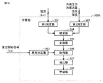
- FIG. It is a figure for demonstrating the structural example of the learning part in Embodiment 3.
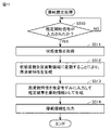
- FIG. This is an example of a flowchart of the learning process in the learning unit in the third embodiment.
- This is an example of a flowchart of the estimation process in the estimation unit in the fourth embodiment.
- the forms of the components shown in all the embodiments described below are merely examples, and are not limited to the forms described below.
- the combination of components is not limited to the combination in each embodiment, and the components described in other embodiments can be applied to other embodiments.
- the high and low of parameters such as pressure and temperature, the high and low are not determined in relation to the absolute value, but are relatively determined by the state and operation of the device and the like.
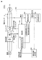
- FIG. 1 is a block diagram for explaining an example of the configuration of the failure diagnosis system SYS1 according to the first embodiment.
- the failure diagnosis system SYS1 shown in FIG. 1 includes a compressor 50 including an electric motor (not shown) which is a target of failure diagnosis, and a failure diagnosis device 1000 for diagnosing a failure of the electric motor.
- the configuration for driving the compressor 50 includes an AC power supply 1, a rectifier circuit 2, an electrolytic capacitor 3, and an inverter 4.
- the rectifier circuit 2 converts the three-phase (UVW phase) AC power from the AC power supply 1 into DC power.
- the electrolytic capacitor 3 smoothes the DC power from the rectifier circuit 2.
- the inverter 4 converts the DC power from the rectifier circuit 2 into three-phase AC power, and outputs the three-phase AC power to the compressor 50.
- the voltage sensor 5 detects the bus voltage Vdc applied to the electrolytic capacitor 3.
- the current sensor 6 is provided in the middle of the wiring 7 from the inverter 4 to the compressor 50, and detects two-phase currents (for example, current Iu and current Iv) in the three-phase AC flowing from the inverter 4 to the compressor 50. do.
- the configuration for driving the compressor 50 includes a control unit 100 for controlling the drive of the compressor 50.
- the control unit 100 outputs a voltage command value (Vuvw_ref) to the inverter 4 based on the results detected by the voltage sensor 5 and the current sensor 6, and drives the compressor 50 by PWM (Pulse Width Modulation) control.
- the control unit 100 not only controls the drive of the compressor 50, but also functions as a part of the configuration of the failure diagnosis device 1000.
- the failure diagnosis device 1000 includes a control unit 100, a wear estimation unit 200, a failure notification unit 300, and a wear diagnosis generation unit 400.
- the failure diagnosis device 1000 can be realized by hardware such as a computer that executes various programs, and the arithmetic unit that executes various processes includes, for example, a CPU (Central Processing Unit) and an FPGA (Field-Programmable Gate). Array) etc. are used.
- a CPU Central Processing Unit
- FPGA Field-Programmable Gate
- the control unit 100 has a wear estimation determination device 101. Further, the control unit 100 is a wear estimation unit based on the failure diagnosis start signal Fs from the wear diagnosis generation unit 400, the bus voltage Vdc from the voltage sensor 5, and the two-phase current Iuv in the three-phase alternating current.
- the estimation start signal Es and the phase estimation value ⁇ _est are output to 200.
- the phase estimated value ⁇ _est is a value estimated by the control unit 100 based on the currents of two phases of the three-phase alternating current detected by the current sensor 6.
- the wear estimation unit 200 estimates the degree of deterioration (wear amount) of the bearing of the motor that drives the compressor 50 from the currents of the two phases of the three-phase alternating current, the estimation start signal Es, and the phase estimation value ⁇ _est. ..
- the wear amount of the bearing of the motor will be described below, but the present invention is not limited to this.
- the wear estimation unit 200 sets the estimated wear amount as the wear estimation amount W_est and outputs the estimated wear amount to the failure notification unit 300 and the wear diagnosis generation unit 400.
- the amount of wear of the bearing of the motor is one of the wear information.
- the degree of deterioration is not limited to the three-phase alternating current, and three of the three-phase alternating currents are used.
- a phase or one-phase current may be used to estimate the degree of deterioration of the motor bearings.
- the failure notification unit 300 notifies the replacement time of the compressor 50 according to the wear estimation amount W_est estimated by the wear estimation unit 200.
- the wear diagnosis generation unit 400 outputs a failure diagnosis start signal Fs for starting the wear estimation of the bearing of the motor to the wear estimation determination device 101 of the control unit 100 according to the wear estimation amount W_est estimated by the wear estimation unit 200.
- FIG. 2 is a cross-sectional view showing an example of the internal structure of the compressor 50.
- the compressor 50 shown in FIG. 2 includes a suction pipe 51, a spindle 52, an electric motor 53, a lubricating oil 54, an oil pump 55, an auxiliary bearing 56, a main bearing 57, a compression mechanism 58, and a discharge pipe 59. including.
- the compressor 50 constitutes a part of the air conditioning equipment and forms a refrigerating cycle for compressing the refrigerant flowing through the pipe. Further, the refrigerant is sucked from the suction pipe 51 of the compressor 50 and discharged from the discharge pipe 59.
- the suction pipe 51 is a pipe for sucking a low-temperature and low-pressure refrigerant into the compressor 50.
- a pressure sensor, a temperature sensor, a humidity sensor, or the like may be attached to the suction pipe 51 to measure the pressure, temperature, humidity, and the like of the refrigerant flowing in the pipe. Further, these sensors may be attached to the pipes in the air conditioner to estimate the pressure, temperature, humidity and the like of the refrigerant flowing in the suction pipe 51.
- the motor 53 is connected to a three-phase alternating current power line and is driven according to the voltage applied from the inverter 4.
- the spindle 52 is connected to the motor 53 and transmits rotational energy to the compression mechanism 58.
- the lubricating oil 54 is accumulated in the bottom of the compressor 50 and is supplied to the auxiliary bearing 56 and the main shaft 52 by the oil pump 55 to lubricate the auxiliary bearing 56 and the main shaft 52.
- a liquid level sensor capable of detecting the height of the oil level of the lubricating oil 54 may be attached to measure the amount of the lubricating oil 54.
- the discharge pipe 59 is a pipe for discharging the high-temperature and high-pressure refrigerant compressed by the compression mechanism 58 to the outside of the compressor 50.
- a pressure sensor, a temperature sensor, a humidity sensor, or the like may be attached to the discharge pipe 59 to measure the pressure, temperature, humidity, and the like of the refrigerant flowing in the pipe. Further, these sensors may be attached to the pipes in the air conditioner to estimate the pressure, temperature, humidity and the like of the refrigerant flowing in the discharge pipe 59.
- FIG. 3 is a cross-sectional view of the main shaft 52 and the main bearing 57 of the compressor 50. Note that FIG. 3A shows a cross-sectional view of the main shaft 52 and the main bearing 57 in a lubricated state during normal driving, and FIG. 3B shows a cross-sectional view of the main shaft 52 and the main bearing 57 in a lubricated state. Instead, a cross-sectional view of the abnormal drive is shown. As shown in FIG.
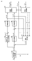
- FIG. 4 is a control block diagram of the control unit 100.
- the control unit 100 includes a wear estimation determination device 101, an excitation current command generator 102, a PI (proportional integral) controller 103, a coordinate converter 104, a PI controller 105, a PI controller 106, and coordinate conversion.
- the device 107 and the speed estimator 108 are included.
- the wear estimation determination device 101 receives the failure diagnosis start signal Fs from the wear diagnosis generation unit 400, outputs the estimation start signal Es to the wear estimation unit 200, and generates the speed command value ⁇ _ref.
- the excitation current command generator 102 generates an excitation current command value Id_ref according to the velocity command value ⁇ _ref.
- the PI controller 103 performs proportional integral control based on the difference value between the excitation current command value Id_ref and the d-axis current Id converted by the coordinate converter 107 to calculate the d-axis voltage command value Vd_ref, and calculates the d-axis voltage command value Vd_ref.
- the command value Vd_ref is output to the coordinate converter 104.
- the coordinate converter 104 coordinates the d-axis voltage command value Vd_ref from the PI controller 103 and the q-axis voltage command value Vq_ref from the PI controller 106 based on the phase estimation value ⁇ _est estimated by the speed estimator 108.
- the conversion process is performed, the voltage command value Vuvw_ref of the three-phase AC is calculated, and the voltage command value Vuvw_ref is output to the inverter 4.
- the PI controller 105 performs proportional integral control based on the difference value between the speed command value ⁇ _ref and the speed estimated value ⁇ _est estimated by the speed estimator 108 to calculate the q-axis current command value Iq_ref, and the q-axis current command.
- the value Iq_ref is output to the PI controller 106.
- the PI controller 106 performs proportional integral control based on the difference value between the q-axis current command value Iq_ref and the q-axis current Iq converted by the coordinate converter 107 to calculate the q-axis voltage command value Vq_ref, and calculates the q-axis voltage command value Vq_ref.
- the voltage command value Vq_ref is output to the coordinate converter 104.
- the velocity estimator 108 estimates the velocity estimation value ⁇ _est and the phase estimation value ⁇ _est based on the d-axis voltage command value Vd_ref, the q-axis voltage command value Vq_ref, and the d-axis current Id and the q-axis current Iq. Then, the estimated speed estimation value ⁇ _est is output to the PI controller 105, and the estimated phase estimation value ⁇ _est is output to the coordinate converter 104, the coordinate converter 107, and the wear estimation unit 200.
- the velocity estimator 108 estimates the velocity estimation value ⁇ _est and the phase estimation value ⁇ _est by applying, for example, an adaptive magnetic flux observer which is a known technique.
- the applied magnetic flux observer is excellent in that it has robustness against fluctuations in the number of interlinkage magnetic fluxes and does not cause an error in steady velocity estimation. For this reason, the adaptive flux observer is widely recognized as a high-performance velocity estimation method.
- the velocity estimator 108 is not limited to the configuration in which the velocity is estimated by using the adaptive magnetic flux observer.
- the control unit 100 estimates the speed of the electric motor 53 that drives the compressor 50, and controls the speed of the electric motor 53 so as to follow the speed command value ⁇ _ref generated by the wear estimation determination device 101. Can be done.
- FIG. 5 is a flowchart for explaining an example of processing in the control unit 100.
- FIG. 5 describes a control flow of the wear estimation determination device 101.
- the wear estimation determination device 101 determines whether or not the failure diagnosis start signal Fs from the wear diagnosis generation unit 400 is an “ON” signal (step S101).
- the wear estimation determination device 101 determines that the failure diagnosis is to be started, and generates a command value so that the speed command value ⁇ _ref becomes a constant value. Then, the speed command value ⁇ _ref is output to the exciting current command generator 102 and the PI controller 105 (step S102).
- the wear estimation determination device 101 generates the speed command value ⁇ _ref, and then outputs the estimation start signal Es of the “ON” signal to the wear estimation unit 200 (step S103).
- the wear estimation unit 200 performs a process of estimating the amount of wear of the main bearing 57 by receiving the estimation start signal Es.
- the wear estimation determination device 101 determines that the compressor 50 is normally operated (step S104). In the case of normal operation, the wear estimation determination device 101 generates a speed command value ⁇ _ref according to the load state of the compressor 50, and outputs the speed command value ⁇ _ref to the exciting current command generator 102 and the PI controller 105. .. For example, the wear estimation determination device 101 generates a high speed command value ⁇ _ref when the load state of the compressor 50 is high, and generates a low speed command value ⁇ _ref when the load state of the compressor 50 is low, and the load state.
- the wear estimation determination device 101 generates a speed command value ⁇ _ref that drives the motor 53 constantly in order to start the failure diagnosis when the failure diagnosis start signal Fs is an “ON” signal. , "OFF" signal, the speed command value ⁇ _ref corresponding to the load state of the compressor 50 is generated for normal operation.
- FIG. 6 is a diagram illustrating the relationship between the operating state of the motor 53 and the current of the motor 53.
- FIG. 6A illustrates changes in the speed command value and the current value while the motor 53 is being accelerated and driven.
- the horizontal axis is the elapsed time (sec) and the vertical axis is the speed command value (rad / sec).
- the horizontal axis is the elapsed time (note that the scale is different from the elapsed time in the upper graph)
- the vertical axis is the current value of the U phase of the motor 53.
- FIG. 6B illustrates changes in the speed command value and the current value while the motor 53 is being driven constantly.
- the horizontal axis is the elapsed time (sec) and the vertical axis is the speed command value (rad / sec).
- the horizontal axis is the elapsed time (note that the scale is different from the elapsed time in the upper graph), and the vertical axis is the current value of the U phase of the motor 53.
- the period Ta, the period Tb, and the period Tc shown in FIG. 6 represent one cycle of the current of the motor 53 at a certain time point.
- the speed command value ⁇ _ref increases with the passage of time, and the amplitude of the current of the electric motor 53 gradually increases.
- the speed command value ⁇ _ref increases, the length of one cycle of the current of the motor 53 gradually shortens (Ta> Tb).
- the speed command value ⁇ _ref becomes lower with the passage of time, and the amplitude of the current of the motor 53 gradually becomes smaller.
- the speed command value ⁇ _ref decreases, the length of one cycle of the current of the motor 53 gradually increases (Ta ⁇ Tb).
- the speed command value ⁇ _ref becomes constant, and the amplitude of the current of the motor 53 also becomes constant. Further, when the speed command value ⁇ _ref is constant, the length of one cycle of the current of the motor 53 is also constant (Tc). Therefore, when the motor 53 of the compressor 50 is constantly driven, the fluctuation of the current of the motor 53 is smaller than that of the case where the motor 53 is being driven for acceleration / deceleration, and the condition is that the amount of wear of the main bearing 57 is estimated.
- the constant drive is preferably a state in which the rotation speed of the electric motor 53 is driven within ⁇ 1% of the target rotation speed. If the rotation speed is in this section, the accuracy of estimating the friction information can be improved. It is desirable that the rotation speed is substantially the same and does not change because the accuracy of estimating the friction information is further improved.
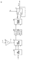
- FIG. 7 is a control block diagram showing an example of the wear estimation unit 200.
- the wear estimation unit 200 includes a three-phase converter 201, a phase converter 202, a coordinate converter 203, a low-pass filters 204 and 205, an absolute value calculator 206, and a switch 207.
- the three-phase converter 201 calculates the W-phase current Iw from the two-phase currents (Iu, Iv) using Equation 1, and outputs the three-phase alternating current Iuvw to the coordinate converter 203.
- the phase converter 202 the phase estimated value ⁇ _est from the speed estimator 108 is inverted, and the inverted phase estimated value ⁇ _est is calculated.
- the coordinate converter 203 performs coordinate conversion processing on the three-phase alternating current Iuvw using the phase estimation value ⁇ _est inverted by the phase converter 202, and the two-axis DC component orthogonal to the three-phase alternating current Iuvw. Convert to.
- the low-pass filters 204 and 205 remove the AC component from the two-axis DC component converted by the coordinate converter 203, and extract only the necessary DC component.
- the absolute value calculator 206 the absolute value of the DC component of the two axes, that is, the square root value of the sum of squares is obtained to obtain the reverse phase current value. Further, the absolute value calculator 206 calculates the wear estimation amount W_est1 according to the reverse phase current value, and outputs the wear estimation amount W_est1 to the switch 207.
- the coordinate converter 203 and the low-pass filters 204 and 205 are band-pass filters specialized for the current component that rotates in the opposite direction, have the effect of extracting the DC component, and function as a simple and high-performance filter. ing.
- the switch 207 switches whether or not to output the wear estimation amount W_est1 according to the estimation start signal Es. Specifically, when the estimation start signal Es is an "ON" signal, the switch 207 outputs the wear estimator W_est1 output from the absolute value calculator 206, and the estimation start signal Es is an "OFF" signal. In this case, the previous wear estimation amount W_est is output as the wear estimation amount W_est2.
- FIG. 8 is a diagram illustrating an example of a display form of the replacement time of the compressor 50.
- the failure notification unit 300 notifies the user of the period until the failure according to the value of the wear estimation amount W_est based on the reference shown in FIG. 8 (a).
- the wear estimation amount W_est is large, the display period of the failure notification unit 300 is set to be short. For example, if the wear estimation amount is 0 " ⁇ m", the failure notification unit 300 sets "12 months” as the display period. If the estimated wear amount is less than 20 “ ⁇ m”, the failure notification unit 300 sets "10 months” as the display period. If the estimated wear amount is less than 40 " ⁇ m”, the failure notification unit 300 sets "8 months” as the display period.
- the failure notification unit 300 sets "6 months” as the display period. If the estimated wear amount is less than 80 " ⁇ m”, the failure notification unit 300 sets "4 months” as the display period. If the estimated wear amount is less than 100 " ⁇ m”, the failure notification unit 300 sets "2 months” as the display period. Further, according to the display period set in FIG. 8A, for example, the failure notification unit 300 should replace the compressor within ⁇ as shown in FIG. 8B. Is displayed on the display (not shown) to urge the user to replace the compressor 50.
- ⁇ means the display period.
- the target for which the failure notification unit 300 prompts the user to replace is not limited to the compressor 50, but may be the electric motor 53 or the main bearing 57 of the electric motor 53.
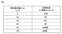
- FIG. 9 is a diagram illustrating an example of the notification timing of the diagnosis time.
- the wear diagnosis generation unit 400 performs failure diagnosis at a diagnosis time according to the value of the wear estimation amount W_est based on the reference shown in FIG.
- the wear diagnosis generation unit 400 issues a failure diagnosis start signal Fs to the control unit 100 for each diagnosis period shown in FIG.
- the wear diagnosis generation unit 400 is set so that the diagnosis period is shortened if the wear estimation amount W_est is large. For example, if the wear estimation amount is 0 “ ⁇ m”, the wear diagnosis generation unit 400 issues a failure diagnosis start signal Fs at intervals of “30 days”. Further, if the wear estimation amount is less than 20 " ⁇ m", the wear diagnosis generation unit 400 issues a failure diagnosis start signal Fs at intervals of "7 days".
- the wear diagnosis generation unit 400 issues a failure diagnosis start signal Fs at intervals of "3 days”. Further, if the wear estimation amount is less than 60 “ ⁇ m”, the wear diagnosis generation unit 400 issues a failure diagnosis start signal Fs at intervals of "1 day”. Further, if the wear estimation amount is less than 80 " ⁇ m”, the wear diagnosis generation unit 400 issues a failure diagnosis start signal Fs at intervals of "12 hours”. Further, if the wear estimation amount is less than 100 " ⁇ m”, the wear diagnosis generation unit 400 issues a failure diagnosis start signal Fs at intervals of "1 hour”.
- the fact that the wear diagnosis generation unit 400 issues the failure diagnosis start signal Fs means that the failure diagnosis start signal Fs of the "ON" signal is output, and other than that, the failure of the "OFF” signal.
- the diagnosis start signal Fs is output.
- the wear diagnosis generation unit 400 sets the diagnosis time in a period shorter than the period in which the failure notification unit 300 displays a display prompting the user to replace the compressor 50. That is, the wear diagnosis generation unit 400 generates a signal indicating the start of the failure diagnosis in a period shorter than the period in which the failure notification unit 300 notifies the user of information based on the wear information (for example, information prompting the replacement of the compressor 50). do.
- the failure diagnosis device 1000 diagnoses the failure of the electric motor that drives the device.
- the failure diagnosis device 1000 is estimated by the control unit 100 that controls the drive of the motor 53, the wear estimation unit 200 that estimates the wear amount of the bearing of the motor 53 based on the current flowing through the motor 53, and the wear estimation unit 200.
- a failure notification unit 300 for diagnosing a failure of the motor 53 and notifying the user based on the amount of wear of the bearing of the motor 53 is provided.
- the control unit 100 controls the drive of the motor 53 so that the motor 53 is driven constantly.
- the failure diagnosis device 1000 estimates the amount of wear of the bearing while the motor 53 is in constant drive, so that the amount of wear can be estimated more accurately than when the motor 53 is in acceleration / deceleration drive, and unexpected downtime is suppressed. Appropriate maintenance measures can be taken.
- control unit 100 may control the motor 53 by driving the rotation speed to be constant (for example, generate a command value so that the speed command value ⁇ _ref becomes a constant value).
- control unit 100 can control the electric motor 53 by driving the rotation speed to be constant, and cause the wear estimation unit 200 to estimate the amount of wear of the bearing while the electric motor 53 is constantly driven.
- a wear diagnosis generation unit 400 that generates a signal indicating the start of failure diagnosis to the control unit 100 based on the wear amount estimated by the wear estimation unit 200.
- the control unit 100 can control the start of the failure diagnosis based on the signal indicating the start of the failure diagnosis (fault diagnosis start signal Fs).
- the wear diagnosis generation unit 400 generates a signal indicating the start of the failure diagnosis in a shorter period than the period in which the failure notification unit 300 notifies the user of the information based on the wear information.
- the failure notification unit 300 notifies the user of the replacement time of the bearing of the motor 53 based on the wear amount of the bearing of the motor 53 estimated by the wear estimation unit 200.
- the failure notification unit 300 can appropriately urge the user to replace the bearing of the motor 53 or the motor 53, and can make the user aware of the timing of performing maintenance in advance, which is appropriate. Maintenance measures can be taken.
- the failure diagnosis system SYS1 controls the driving of the electric motor 53 by outputting a voltage command to the electric motor 53 for driving the equipment, the inverter 4 for supplying power to the electric motor 53, and the inverter 4.
- the motor 53 is based on the wear estimation unit 200 that estimates the wear amount of the bearing of the motor 53 based on the control unit 100 and the current flowing through the motor 53, and the wear amount of the bearing of the motor 53 estimated by the wear estimation unit 200. It is provided with a failure notification unit 300 that diagnoses the failure and notifies the user of the failure.
- the wear estimation unit 200 estimates the amount of wear of the bearing of the motor 53
- the control unit 100 controls the drive of the motor 53 so that the motor 53 is driven constantly.
- the failure diagnosis system SYS1 estimates the amount of wear of the bearing while the motor 53 is in constant drive, so that the amount of wear can be estimated more accurately than when the motor 53 is in acceleration / deceleration drive, and unexpected downtime is suppressed. Appropriate maintenance measures can be taken.
- Embodiment 2 In the failure diagnosis device 1000 of the first embodiment, a configuration is described in which control is performed to drive the electric motor 53 constantly and the amount of wear of the bearing of the electric motor 53 is estimated while the electric motor 53 is constantly driven.
- FIG. 10 is a control block diagram of the control unit 100 according to the second embodiment.
- the input / output information of the wear estimation determination device 109 is different from that of the first embodiment.
- the other configurations of the failure diagnosis system according to the second embodiment are the same as the configurations of the first embodiment, and the same configurations are designated by the same reference numerals and detailed description thereof will not be repeated.
- the wear estimation determination device 109 has a failure diagnosis start signal Fs, a bus voltage Vdc from the voltage sensor 5, a d-axis voltage command value Vd_ref from the PI controller 103, and the PI controller 106.
- the q-axis voltage command value Vq_ref of is input. That is, the wear estimation determination device 109 generates the estimation start signal Es and the speed command value ⁇ _ref in consideration of the bus voltage Vdc, the d-axis voltage command value Vd_ref, and the q-axis voltage command value Vq_ref.
- FIG. 11 is a flowchart for explaining an example of processing in the control unit 100 according to the second embodiment.
- FIG. 11 describes a control flow of the wear estimation determination device 109.
- the wear estimation determination device 109 determines whether or not the failure diagnosis start signal Fs from the wear diagnosis generation unit 400 is an “ON” signal (step S101).
- the wear estimation determiner 109 calculates the modulation factor based on the bus voltage Vdc, the d-axis voltage command value Vd_ref, and the q-axis voltage command value Vq_ref. (Step S105). Specifically, the wear estimation determination device 109 calculates the modulation factor Duty using the following (Equation 2).
- the wear estimation determination device 109 determines whether or not the calculated modulation factor Duty is equal to or greater than the preset value A and less than the preset value B (step S106).
- the wear estimation determiner 109 determines that the failure diagnosis is to be started, and the speed command value ⁇ _ref is set.
- a command value is generated so as to be a constant value, and the speed command value ⁇ _ref is output to the exciting current command generator 102 and the PI controller 105 (step S102).
- the wear estimation determination device 109 generates the speed command value ⁇ _ref and then outputs the estimation start signal Es of the “ON” signal to the wear estimation unit 200 (step S103).
- the wear estimation unit 200 performs a process of estimating the amount of wear of the main bearing 57 by receiving the estimation start signal Es.
- step S101 when the failure diagnosis start signal Fs is an "OFF" signal (NO in step S101), or when the calculated modulation factor Wear is less than the preset value A or greater than or equal to the preset value B (in step S106). NO), the wear estimation determination device 109 determines that the compressor 50 is normally operated (step S104).
- the preset value A may be set to a value less than 1 at which voltage saturation occurs, and is set to 0.9 in consideration of load fluctuation of the compressor 50, for example. Further, the preset value B is set to less than 1 at which voltage saturation does not occur.
- FIG. 12 is a diagram illustrating an error in estimating the amount of wear with respect to the speed of the motor 53.
- the horizontal axis shown in FIG. 12 represents the speed (rotational speed) of the motor 53, and the vertical axis represents the wear estimation error of the main bearing 57.
- the wear estimation error is the difference between the absolute values of the wear estimation amount W_est and the actual wear amount.
- the actual amount of wear is the amount of wear when the bearing is shaved to a predetermined value in advance to reproduce the wear.
- the wear estimation error is large at the speed of the motor 53, it is not suitable for the period for estimating the wear amount, and conversely, if the wear estimation error is small, it is suitable for estimating the wear amount. It is a period.
- the speed of the motor 53 is low (region of modulation factor ⁇ 1), the speed estimation error is easily affected in the speed estimator 108, so that an error occurs in the phase estimation value ⁇ _est. Therefore, the wear estimation error becomes large, and a modulation factor smaller than the preset value A is not suitable for the period for estimating the wear amount.
- the wear estimation determination device 109 generates a command value so that the speed command value ⁇ _ref becomes a constant value in the range where the modulation factor is equal to or higher than the preset value A and less than the preset value B, thereby causing wear. Since the wear estimation error in the estimation unit 200 becomes small, it can be determined that it is suitable for the period for estimating the wear amount.
- step S101 to step S104 are the same as the contents described in the first embodiment.
- the failure diagnosis device 1000 determines whether or not the control unit 100 controls to drive the electric motor 53 constantly based on the calculated modulation factor. As a result, the failure diagnosis device 1000 can determine the speed command value of the electric motor 53 according to the modulation factor and estimate the wear amount. Therefore, the wear amount is estimated in consideration of the influence of the load fluctuation of the compressor 50. Can be carried out accurately. Further, in the second embodiment, unexpected downtime can be suppressed and appropriate maintenance measures can be taken.
- the control unit 100 preferably controls to drive the motor constantly. As a result, the control unit 100 determines the speed command value when the modulation factor is in the vicinity of 1, and estimates the wear amount. Therefore, the accuracy of estimating the wear amount deteriorates due to the phase estimation error in the low speed range, and the voltage in the high speed range. It is possible to suppress deterioration of the estimation accuracy of the amount of wear due to saturation.
- Embodiment 3 In the failure diagnosis device 1000 according to the third embodiment, a configuration for estimating wear information (wear amount) of the bearing of the motor 53 by using so-called artificial intelligence (AI) will be described.
- AI artificial intelligence
- the learning process will be described first, prior to the explanation of estimating the wear information of the main bearing 57 of the electric motor 53.
- This learning process is a process for generating an estimation model used for estimating wear information of a bearing of a motor.
- the process of estimating the wear information of the bearing of the motor using the estimation model generated in the third embodiment will be described.
- FIG. 13 is a block diagram for explaining an example of the configuration of the failure diagnosis system SYS2 in the third embodiment.
- the failure diagnosis system SYS2 in the third embodiment has the same configuration as the failure diagnosis system SYS1 in the first embodiment except that the wear estimation unit 200 is different from the wear estimation unit 500, and the same configuration has the same reference numeral. Do not repeat the detailed explanation.
- the wear estimation unit 500 differs from the wear estimation unit 200 in input / output information and internal processing.
- the wear estimation unit 500 includes an estimation start signal Es from the control unit 100, two-phase currents (for example, Iu and Iv) in the three-phase AC detected by the current sensor 6, and the pressure of the refrigerant in the compressor 50.
- the state quantity including the temperature around the compressor 50, the humidity around the compressor 50, and the flow rate of the refrigerant is acquired.
- the "refrigerant pressure in the compressor 50" is referred to as “refrigerant pressure”.
- the "temperature around the compressor 50" is called “temperature”.
- Humidity around the compressor 50” is called “humidity”.
- the "refrigerant flow rate” is called “refrigerant flow rate”.
- Refrigerant pressure, temperature, humidity, and refrigerant flow rate are state quantities indicating the operating state of the air conditioner. Then, the wear estimation unit 500 sets the wear estimation amount W_est estimated by artificial intelligence based on the current of two phases in the three-phase AC detected by the current sensor 6 and the state amount indicating the operating state to the failure notification unit 300. And output to the wear diagnosis generation unit 400.
- the wear estimation unit 500 includes a learning unit 500A and an estimation unit 500B. First, the learning unit 500A will be described.
- FIG. 14 is a diagram for explaining a configuration example of the learning unit 500A in the third embodiment.
- the learning unit 500A includes a first measuring device 501, a second measuring device 502, a wear determining device 503, an observing device 504, a converter 505, an acquirer 506, an extractor 507, and a learning device 508. Have.
- the first measuring instrument 501 measures the current (Iuv) of two phases of the three-phase alternating current detected by the current sensor 6.
- the first measuring instrument 501 outputs the detected current to the observer 504 as time series data. Further, the current detected by the current sensor 6 is also referred to as a "first state variable".
- the second measuring instrument 502 outputs the refrigerant pressure, temperature, humidity, and refrigerant flow rate to the observer 504 as time series data.
- Refrigerant pressure, temperature, humidity, and refrigerant flow rate are also referred to as "second state variables" or “variables indicating the operating state of air conditioning equipment”.
- the second state variable is not limited to including all information on refrigerant pressure, temperature, humidity, and refrigerant flow rate, and even if it is at least one piece of information on refrigerant pressure, temperature, humidity, and refrigerant flow rate, the refrigerant pressure,
- the temperature, humidity, and refrigerant flow information may include additional information (eg, operating noise around the compressor 50).
- the first state variable and the second state variable are collectively referred to as a "state variable".
- the "state variable” may be expressed as a "parameter” or a "feature amount”.
- the observer 504 acquires each state variable from these time-series data by observing the time-series data from the first measuring instrument 501 and the second measuring instrument 502.
- Each state variable acquired by the observer 504 is input to the converter 505.
- the converter 505 converts each of the acquired state variables into a frequency domain.
- the converter 505 transforms each of the acquired state variables into a frequency domain, for example, by Fourier transform or fast Fourier transform.
- the converter 505 may convert each of the acquired state variables into a frequency domain by another method.
- the frequency characteristics of each state variable converted into the frequency domain by the converter 505 are output to the acquirer 506.
- the wear determination device 503 determines the wear of the main bearing 57 of the electric motor 53 by using, for example, a predetermined method.
- the wear determination device 503 generates wear information independently of the wear information estimated by the estimation unit 500B described in the fourth embodiment.
- the wear information includes at least information on the amount of wear of the main bearing 57 of the motor 53, and may include other information such as the presence or absence of wear of the main bearing 57 of the motor 53. Further, the wear determining device 503 determines whether or not to estimate the wear information based on the estimation start signal Es.
- the wear determining device 503 reproduces the wear state of the main bearing 57 of the electric motor 53 in a simulation environment simulating the estimation unit 500B described in the fourth embodiment, and outputs wear information in response to the wear state. You may estimate.
- the wear information generated by the wear determination device 503 is input to the acquirer 506.
- the acquirer 506 acquires a learning data set including a plurality of learning data in which bearing wear information is labeled with the frequency characteristics of each state variable of the motor 53.
- the acquirer 506 acquires, for example, the frequency characteristics of each state variable converted by the converter 505 in association with the wear information generated by the wear determiner 503 as a learning data set.
- the extractor 507 also extracts frequency characteristics from the learning data set.
- the learner 508 inputs the frequency characteristics extracted from the training data set into the estimation model so that the estimation result output from the estimation model approaches the wear information labeled in the training data set. , Optimize the parameters of the estimation model.
- the estimation model includes, for example, a neural network and the parameters used by the neural network.
- FIG. 15 is an example of a flowchart of the learning process in the learning unit 500A in the third embodiment.
- the learning unit 500A determines in the wear determination device 503 to determine the start of estimation of wear information based on whether or not the estimation start signal Es from the wear estimation determination device 101 is an “ON” signal (step S501). When the estimation start signal Es is an "OFF" signal (NO in step S501), the learning unit 500A returns the process to step S501.
- the learning unit 500A when the estimation start signal Es is an "ON" signal (YES in step S501), the learning unit 500A generates wear information in the wear determination device 503 and acquires the generated wear information in the acquirer 506 (YES in step S501). Step S502).
- the learning unit 500A acquires each state variable from the time-series data of the first measuring instrument 501 and the second measuring instrument 502 by the observer 504 (step S503).
- the learning unit 500A generates the frequency characteristics of each state variable by converting each acquired state variable into a frequency domain by the converter 505 (step S504).
- the learning unit 500A associates the wear information acquired in step S502 with the frequency characteristics generated in step S504 and generates it as a learning data set (step S505).
- the learning unit 500A selects one learning data from a plurality of learning data included in the learning data set in the extractor 507 (step S506).
- the learning unit 500A extracts each frequency characteristic from the selected learning data in the extractor 507 (step S507).
- the learning unit 500A inputs each extracted frequency characteristic into the estimation model in the extractor 507 to generate an estimation result (step S508).
- the learning unit 500A optimizes the parameters of the estimation model in the learning device 508 based on the error between the wear information of the training data selected in step S506 and the estimation result generated in step S508 (step S509). ..
- the learning unit 500A determines whether or not all of the generated learning data sets have been processed by the learning device 508 (step S510). When it is determined that all of the training data sets have not been processed (NO in step S510), the learning unit 500A returns the processing to step S506. On the other hand, when it is determined that all of the learning data sets have been processed (YES in step S510), the learning unit 500A ends the learning process.
- the learning unit 500A can appropriately generate a trained estimation model when the learning process is completed.
- the learning unit 500A executes a learning process based on so-called supervised learning using the wear information generated by the wear determining device 503.
- the learning process in the learning unit 500A is not limited to the learning process based on supervised learning, and the learning process based on so-called unsupervised learning may be executed.
- the learning process based on unsupervised learning is for learning how the input data is distributed by giving a large amount of input data (for example, each frequency characteristic) to the learning unit 500A, and corresponding learning. It is a process of compressing, classifying, shaping, and learning the input data without giving correct answer information (for example, wear information) to the data set.
- the learning unit 500A clusters the characteristics of the learning data set with similar data sets.
- the learning unit 500A may use the result of this clustering to assign some criteria to the output from the estimation model and update the parameters of the estimation model so that the training data set is optimized.
- the learning unit 500A may execute a learning process based on "semi-supervised learning".
- the learning process based on semi-supervised learning is learning with learning data using the corresponding wear information for some of the frequency characteristics, and the corresponding wear for other frequency characteristics. It is a learning process that performs learning without using information.
- the learning unit 500A is a learning device for learning an estimation model for estimating wear information of the bearing of the electric motor 53 that drives the device.
- the estimation model estimates the wear information of the bearing of the motor 53 from the first state variable indicating the current flowing through the motor 53 and the second state variable of at least one of the variables indicating the operating state of the air conditioner.
- the learning unit 500A acquires a learning data set including a plurality of learning data labeled with wear information of the bearing of the electric motor 53 which has been acquired in advance for the first state variable and the second state variable.
- a learner 508 that optimizes the estimation model so that the estimation result approaches the wear information of the bearing of the motor 53 labeled with the learning data set acquired by the acquirer 506.
- the learning unit 500A uses the learning data set to optimize the estimation model so that the estimation result approaches the wear information of the bearing of the motor 53 to which the estimation result is labeled, thereby using the estimation model. It becomes possible to estimate the wear information of the bearing of the motor 53 while the motor 53 is in constant operation with high accuracy.
- the learning unit 500A is a learning method for learning an estimation model for estimating wear information of the bearing of the electric motor 53 that drives the device, and has been acquired in advance for the first state variable and the second state variable.
- the step of acquiring a learning data set containing a plurality of learning data labeled with wear information of the bearing of the electric motor 53, and the bearing of the electric motor 53 to which the estimation result is labeled using the acquired learning data set. Includes steps to optimize the estimation model to get closer to wear information.
- Embodiment 4 the estimation process for estimating the wear information of the main bearing 57 of the electric motor 53 will be described using the estimation model learned in the third embodiment.
- the estimation unit 500B estimates the wear information of the main bearing 57 using the trained estimation model generated in the third embodiment. Further, the estimation unit 500B may acquire the learned estimation model from the learning unit 500A of another failure diagnosis device 2000 via a network (not shown). Further, the estimation unit 500B may be integrated with the learning unit 500A, and the estimation unit 500B may acquire the learned estimation model generated by the learning unit 500A.
- FIG. 16 is a diagram for explaining a configuration example of the estimation unit 500B in the fourth embodiment. Since the failure diagnosis system in the fourth embodiment has the same configuration as the failure diagnosis system SYS2 shown in FIG. 13 of the third embodiment, the same configuration is designated by the same reference numerals and detailed description thereof will not be repeated.
- the estimation unit 500B estimates the wear information of the main bearing 57 of the motor 53 shown in FIG.
- the estimation unit 500B includes a first measuring device 501, a second measuring device 502, an observing device 509, a converter 505, a generator 510, and an output device 511.
- the first measuring instrument 501 measures the current (Iuv) of two phases of the three-phase alternating current detected by the current sensor 6.
- the first measuring instrument 501 outputs the detected current to the observer 509 as time series data.
- the second measuring instrument 502 outputs the refrigerant pressure, temperature, humidity, and refrigerant flow rate as time-series data to the observer 509.
- the observer 509 acquires each state variable from these time-series data by observing the time-series data from the first measuring device 501 and the second measuring device 502 according to the estimation start signal Es.
- the state variable is the state variable described in the third embodiment.
- the converter 505 converts each of the acquired state variables into a frequency domain.
- the generator 510 includes a trained estimation model 5100.
- the trained estimation model 5100 is an estimation model generated by executing a learning process in the learning unit 500A.
- the generator 510 uses the frequency characteristics converted by the transducer 505 and the trained estimation model 5100 to generate wear information for the main bearing 57.
- the trained estimation model 5100 is an estimation model showing the relationship between the frequency characteristics of the state variables converted into the frequency domain by the converter 505 and the wear information of the main bearing 57.
- the output device 511 outputs the wear information of the main bearing 57 generated by the generator 510 as the wear estimation amount W_est.
- the output destinations of the output device 511 are the wear diagnosis generation unit 400 and the failure notification unit 300.
- FIG. 17 is an example of a flowchart of the estimation process in the estimation unit 500B in the fourth embodiment.
- the estimation unit 500B determines the start of estimation of wear information based on whether or not the estimation start signal Es from the wear estimation determination device 101 is an “ON” signal (step S510). When the estimation start signal Es is an "OFF" signal (NO in step S510), the estimation unit 500B returns the process to step S510. On the other hand, when the estimation start signal Es is an "ON" signal (YES in step S510), the estimation unit 500B obtains each state variable from the time series data of the first measuring instrument 501 and the second measuring instrument 502. Acquired in (step S511).
- the estimation unit 500B generates the frequency characteristics of each state variable by converting each acquired state variable into a frequency domain by the converter 505 (step S512).
- the estimation unit 500B inputs the generated frequency characteristics into the trained estimation model 5100 and generates the estimation result as wear information (step S513).
- the estimation unit 500B outputs the generated wear information as a wear estimation amount W_est from the output device 511.
- the estimation unit 500B has the first state variable indicating the current flowing through the electric motor 53 and the air conditioning device based on the estimation model generated by the learning process using the learning data set.
- the wear information of the bearing of the motor 53 is estimated from at least one second state variable among the variables indicating the operating state of the motor 53.
- the learning data set includes a plurality of learning data in which the wear information of the bearing of the motor 53 acquired in advance is labeled with respect to the first state variable and the second state variable.
- the estimation unit 500B uses the estimation model learned so as to approach the wear information of the bearing of the motor 53 to which the estimation result is labeled using the learning data set, and the motor 53 is in constant operation. It becomes possible to estimate the wear information of the bearings of 53 with high accuracy. Since the estimation unit 500B uses the second state variable of the compressor for machine learning in addition to the current of the motor 53, the factors leading to wear are complicated, and it is difficult to set a function for estimating wear information in advance. Even in some cases, it becomes possible to infer wear information with high accuracy.
- the estimation unit 500B may include a converter 505 that converts the first state variable and the second state variable into a predetermined frequency domain and outputs them as the frequency characteristics of the first state variable and the second state variable. preferable. This makes it easy for the estimation unit 500B to input the first state variable and the second state variable into the estimation model and perform a predetermined operation.
- the device is a compressor 50
- the electric motor 53 for driving the compressor 50 is connected to the inverter 4
- the inverter 4 outputs AC power from the bus to the electric motor 53.
- the first state variable is the current flowing from the inverter 4 to the motor 53.
- the second state variable is at least one of the pressure of the refrigerant flowing in the compressor 50, the flow rate of the refrigerant, the temperature around the compressor 50, the operating noise around the compressor 50, and the humidity around the compressor 50. It is preferable to include.
- FIG. 18 is a block diagram for explaining an example of the configuration of the failure diagnosis system SYS3 according to the fifth embodiment.
- the same configurations as the failure diagnosis system SYS1 in the first embodiment and the failure diagnosis system SYS2 in the third embodiment are designated by the same reference numerals, and detailed description thereof will not be repeated.
- the failure diagnosis system SYS3 differs from the failure diagnosis system SYS1 of the first embodiment in the functions of the failure notification unit 600 and the wear diagnosis generation unit 700, and the signal transmission method with other devices.
- the failure diagnosis system SYS3 for example, the rectifier circuit 2, the electrolytic capacitor 3, the inverter 4, the voltage sensor 5, the current sensor 6, the compressor 50, the control unit 100, and the wear estimation unit 200 are set in the field (for example, a building). Install it in the control box on the roof of the building.
- the control box installed in the field is defined as a control unit.
- the control unit has a communication unit that transmits a signal of the wear estimation amount W_est by wire or wirelessly and receives the failure diagnosis start signal Fs by wire or wirelessly.
- the control unit transmits the wear estimation amount W_est to the failure notification unit 600 and the wear diagnosis generation unit 700 using the communication unit. Further, the control unit receives the failure diagnosis start signal Fs from the wear diagnosis generation unit 700 by using the communication unit.
- the failure notification unit 600 is installed indoors (for example, a management room). Further, although not shown, the failure notification unit 600 has a communication unit that receives a signal of the wear estimation amount W_est from the control unit. Further, the failure notification unit 600 has a display or the like that displays the replacement period of the compressor 50 based on the received wear estimation amount W_est and prompts the user to replace the compressor 50 (see FIG. 8).
- the failure notification unit 600 is not limited to a terminal installed indoors such as a management room, and may be a mobile terminal carried by the user. In order to use the mobile terminal as the failure notification unit 600, it is necessary to install software having the same function as the failure notification unit 600 in advance.
- the user can know the replacement period of the compressor 50 on the mobile terminal.
- the replacement period of the compressor 50 is known. be able to.
- the wear diagnosis generation unit 700 may be installed on a server, for example. Although not shown, the wear diagnosis generation unit 700 installed in the server has a communication unit that receives a signal of the wear estimation amount W_est from the control unit and transmits a failure diagnosis start signal Fs to the control unit. Specifically, the wear diagnosis generation unit 700 issues a failure diagnosis start signal Fs to the control unit 100 for each diagnosis period based on the received wear estimation amount W_est (see FIG. 9). The wear diagnosis generation unit 700 may be installed on a server on the cloud. Further, the failure diagnosis start signal Fs may be issued based on the information from the user who knows the replacement period of the compressor 50.
- the wear diagnosis generation unit 700 may be connected so as to be able to communicate with a plurality of control units, and the control unit that has received the signal of the wear estimation amount W_est is diagnosed according to the diagnosis period of the control unit.
- the start signal Fs may be transmitted.
- the failure notification unit 600 can communicate with the wear estimation unit 200, and the wear estimation of the bearing of the motor estimated by the wear estimation unit 200.
- the estimator W_est is acquired by communication.
- the failure notification unit 600 can be installed at a position away from the motor 53, and the replacement time of the motor 53 can be known even at a remote location.
Landscapes
- Power Engineering (AREA)
- Engineering & Computer Science (AREA)
- Physics & Mathematics (AREA)
- General Physics & Mathematics (AREA)
- Biochemistry (AREA)
- Analytical Chemistry (AREA)
- Chemical & Material Sciences (AREA)
- General Health & Medical Sciences (AREA)
- Immunology (AREA)
- Pathology (AREA)
- Life Sciences & Earth Sciences (AREA)
- Health & Medical Sciences (AREA)
- Control Of Electric Motors In General (AREA)
- Control Of Positive-Displacement Pumps (AREA)
Abstract
故障診断装置(1000)は、電動機(53)の駆動を制御する制御部(100)と、電動機(53)に流れる電流に基づいて、電動機(53)の軸受の摩耗量を推定する摩耗推定部(200)と、摩耗推定部(200)で推定した電動機(53)の軸受の摩耗量に基づいて、電動機(53)の故障を診断し、ユーザに通知する故障通知部(300)と、を備える。制御部(100)は、摩耗推定部(200)で電動機(53)の軸受の摩耗量を推定する場合に、電動機(53)が一定駆動するように電動機(53)の駆動を制御する。
Description
本開示では、電動機の故障を診断する故障診断装置、学習装置、学習方法、および故障診断システムに関する。
軸受を有する電動機を搭載している圧縮機において、故障原因の多くは、電動機の軸受の劣化、または軸受の破損に起因する。電動機の軸受が摩耗して劣化した状態で圧縮機を使用すると、劣化により電動機が停止して圧縮機の稼働に大きなダウンタイム(停止時間)が生じ、圧縮機の稼働率を低下させる。
そこで、電動機の軸受が摩耗して劣化する前に、電動機の軸受の劣化を検知し、劣化した電動機の軸受を、たとえば、修理する等の適切な措置を行うことで、圧縮機のダウンタイムを削減または短縮することができ、圧縮機の稼働率を向上させることができる。特許文献1には、機器の複数の劣化度と、複数の状態量と、感度を示す複数のパラメータとの関係を示す数理モデルに対して、診断対象機の複数の状態量を適用し、診断対象機の複数の劣化度を推定する故障診断装置が記載されている。
しかしながら、特許文献1では、電動機がどのような駆動状態で劣化度(摩耗量)を推定するのかについて記載されておらず、仮に電動機が加減速駆動している状態で電動機の軸受の劣化度を推定した場合、推定する劣化度に電動機の駆動状態による誤差が発生し、故障診断の精度が悪化する。故障診断の精度が悪化した場合、故障診断装置は、誤って電動機の軸受が劣化していると診断して、保守対応のため圧縮機を停止させるダウンタイムを発生させる虞があった。
本開示では、上記のような課題を解決するためになされたもので、不測のダウンタイムを抑制し、適切な保守対応を図ることができるように電動機の故障を精度よく推定できる故障診断装置、学習装置、学習方法、および故障診断システムを提供することを目的とする。
本開示に係る故障診断装置は、機器を駆動する電動機の故障を診断する。故障診断装置は、電動機の駆動を制御する制御部と、電動機に流れる電流に基づいて、電動機の軸受の摩耗情報を推定する摩耗推定部と、摩耗推定部で推定した電動機の軸受の摩耗情報に基づいて、電動機の故障を診断し、ユーザに通知する故障通知部と、を備える。制御部は、摩耗推定部で電動機の軸受の摩耗情報を推定する場合に、電動機が一定駆動するように前記電動機の駆動を制御する。
本開示によれば、電動機の軸受の摩耗を精度よく推定でき、不測のダウンタイムを抑制し、適切な保守対応を図ることができる。
以下、実施の形態に係る故障診断装置、学習装置、学習方法、および故障診断システムについて、図面を参照しながら説明する。ここで、各図面において、同一の符号を付した構成は、同一またはこれに相当する構成であり、以下に記載するすべての実施の形態において共通の構成であるとする。
また、以下に記載するすべての実施の形態に表わされている構成要素の形態は、あくまでも例示であって、以下に記載された形態に限定するものではない。特に、構成要素の組み合わせは、各実施の形態における組み合わせのみに限定するものではなく、他の実施の形態に記載した構成要素を、別の実施の形態に適用することができる。さらに、圧力、温度などのパラメータの高低については、特に絶対的な値との関係で高低が定まるものではなく、装置などの状態、動作において相対的に定まるものとする。
実施の形態1.
実施の形態1の故障診断システムSYS1について、図面を参照して説明する。図1は、実施の形態1における故障診断システムSYS1の構成の一例を説明するためのブロック図である。図1に示す故障診断システムSYS1は、故障診断の対象である電動機(図示せず)を含む圧縮機50と、当該電動機の故障を診断する故障診断装置1000とを含む。
実施の形態1の故障診断システムSYS1について、図面を参照して説明する。図1は、実施の形態1における故障診断システムSYS1の構成の一例を説明するためのブロック図である。図1に示す故障診断システムSYS1は、故障診断の対象である電動機(図示せず)を含む圧縮機50と、当該電動機の故障を診断する故障診断装置1000とを含む。
圧縮機50を駆動する構成には、交流電源1と、整流回路2と、電解コンデンサ3と、インバータ4とを含む。整流回路2は、交流電源1からの三相(UVW相)交流電力を直流電力に変換する。電解コンデンサ3は、整流回路2からの直流電力を平滑化する。インバータ4は、整流回路2からの直流電力を三相交流電力に変換し、当該三相交流電力を圧縮機50に出力する。電圧センサ5は、電解コンデンサ3に印加される母線電圧Vdcを検出する。電流センサ6は、インバータ4から圧縮機50に至る配線7の途中に設けられ、インバータ4から圧縮機50に流れる三相交流の内の2相の電流(たとえば、電流Iuおよび電流Iv)を検出する。
さらに、圧縮機50を駆動する構成には、圧縮機50の駆動を制御する制御部100を含む。制御部100は、電圧センサ5および電流センサ6で検出した結果に基づいて、インバータ4に電圧指令値(Vuvw_ref)を出力して圧縮機50をPWM(Pulse Width Modulation)制御で駆動する。実施の形態1では、当該制御部100が圧縮機50の駆動を制御する以外に、故障診断装置1000の構成の一部としても機能する。
故障診断装置1000は、制御部100と、摩耗推定部200と、故障通知部300と、摩耗診断生成部400とを含む。故障診断装置1000は、各種のプログラムを実行するコンピュータなどのハードウェアで実現することができ、各種の処理を実行する演算主体には、たとえば、CPU(Central Processing Unit)、FPGA(Field-Programmable Gate Array)などが用いられる。
制御部100は、摩耗推定判定器101を有している。また、制御部100は、摩耗診断生成部400からの故障診断開始信号Fsと、電圧センサ5からの母線電圧Vdcと、三相交流の内の2相の電流Iuvとに基づいて、摩耗推定部200に推定開始信号Esと位相推定値θ_estとを出力する。ここで、位相推定値θ_estとは、制御部100が電流センサ6で検出した三相交流の内の2相の電流に基づいて電動機の回転速度を推定した値である。
摩耗推定部200は、三相交流の内の2相の電流と、推定開始信号Esと、位相推定値θ_estとから、圧縮機50を駆動する電動機の軸受の劣化度(摩耗量)を推定する。なお、電動機の軸受の劣化度の一例として、以下の電動機の軸受の摩耗量を説明するが、これに限定されない。摩耗推定部200は、推定した摩耗量を摩耗推定量W_estとし、故障通知部300および摩耗診断生成部400に出力する。なお、電動機の軸受の摩耗量は、摩耗情報のうちの1つの情報である。また、本開示では、三相交流の内の2相の電流を用いて電動機の軸受の劣化度を推定する例を説明するが、三相交流に限定されず、また三相交流の内の3相または1相の電流を用いて電動機の軸受の劣化度を推定してもよい。
故障通知部300は、摩耗推定部200で推定した摩耗推定量W_estに応じて圧縮機50の交換時期を通知する。摩耗診断生成部400は、摩耗推定部200で推定した摩耗推定量W_estに応じて制御部100の摩耗推定判定器101に電動機の軸受の摩耗推定を開始させる故障診断開始信号Fsを出力する。
次に、圧縮機50の内部構造の一例について説明する。図2は、圧縮機50の内部構造の一例を示す断面図である。図2に示す圧縮機50は、吸入管51と、主軸52と、電動機53と、潤滑油54、オイルポンプ55と、副軸受56と、主軸受57と、圧縮機構58と、吐出管59とを含む。圧縮機50は、空調機器の一部を構成し、配管を流れる冷媒を圧縮する冷凍サイクルを形成している。また、冷媒は、圧縮機50の吸入管51から吸入され、吐出管59から吐出される。
吸入管51は、低温かつ低圧の冷媒を圧縮機50の内部に吸入するための管である。吸入管51には、圧力センサ、温度センサ、湿度センサなどを取り付け、管内を流れる冷媒の圧力、温度、湿度などを測定してもよい。また、空調機器内の配管にこれらセンサ類を取り付け、吸入管51内を流れる冷媒の圧力、温度、湿度などを推定してもよい。
電動機53は、図示してないが、三相交流の電力線と接続され、インバータ4から印加される電圧に応じて駆動する。主軸52は、電動機53と接続され、回転エネルギーを圧縮機構58に伝える。潤滑油54は、圧縮機50の底部に溜まっており、オイルポンプ55で副軸受56および主軸52に供給され、副軸受56および主軸52を潤滑する。なお、潤滑油54の量を確認する手段として、潤滑油54の油面の高さを検知することができる液面センサを取り付け、潤滑油54の量を測定してもよい。
吐出管59は、圧縮機構58で圧縮された高温かつ高圧の冷媒を圧縮機50の外部に吐出するための管である。吐出管59には、圧力センサ、温度センサ、湿度センサなどを取り付け、管内を流れる冷媒の圧力、温度、湿度などを測定してもよい。また、空調機器内の配管にこれらセンサ類を取り付け、吐出管59内を流れる冷媒の圧力、温度、湿度などを推定してもよい。
さらに、圧縮機50を駆動した場合の主軸52と主軸受57との状態を説明する。図3は、圧縮機50の主軸52および主軸受57の断面図である。なお、図3(a)には、主軸52と主軸受57とが潤滑状態で正常な駆動時の断面図が示され、図3(b)には、主軸52と主軸受57とが潤滑状態でなく異常な駆動時の断面図が示されている。図3(a)のように正常な駆動時、主軸52と主軸受57との間には十分な潤滑油54が満たされており、主軸52が主軸受57に対して一定の隙間を確保して円滑に回転している。一方で、図3(b)のように異常な駆動時、温度、経年劣化などの影響により、潤滑油54の粘度が低くなり、主軸52と主軸受57との間の油膜を確保できなくなる。そのため、主軸52と主軸受57とが一部で接触し、この接触した部分で主軸受57の摩耗が発生する。主軸受57が摩耗した状態で、さらに主軸52を回転し続ければ、主軸受57の摩耗がさらに悪化し、最終的に圧縮機50を停止(ダウンタイム)させて、圧縮機50の稼働率が低下する虞がある。
次に、制御部100での圧縮機50および故障診断装置1000の制御について説明する。図4は、制御部100の制御ブロック図である。制御部100は、摩耗推定判定器101と、励磁電流指令生成器102と、PI(比例積分)制御器103と、座標変換器104と、PI制御器105と、PI制御器106と、座標変換器107と、速度推定器108とを含む。摩耗推定判定器101は、摩耗診断生成部400からの故障診断開始信号Fsを受信して、摩耗推定部200に推定開始信号Esを出力し、速度指令値ω_refを生成する。励磁電流指令生成器102は、速度指令値ω_refに応じて励磁電流指令値Id_refを生成する。PI制御器103は、励磁電流指令値Id_refと座標変換器107で変換したd軸電流Idとの差分値に基づいて比例積分制御を施してd軸電圧指令値Vd_refを算出し、当該d軸電圧指令値Vd_refを座標変換器104に出力する。
座標変換器104は、PI制御器103からのd軸電圧指令値Vd_refおよびPI制御器106からのq軸電圧指令値Vq_refに対して、速度推定器108で推定した位相推定値θ_estに基づいて座標変換処理を施し、三相交流の電圧指令値Vuvw_refを算出し、当該電圧指令値Vuvw_refをインバータ4に出力する。
PI制御器105は、速度指令値ω_refと速度推定器108で推定した速度推定値ω_estとの差分値に基づいて比例積分制御を施してq軸電流指令値Iq_refを算出し、当該q軸電流指令値Iq_refをPI制御器106に出力する。
PI制御器106は、q軸電流指令値Iq_refと座標変換器107で変換したq軸電流Iqとの差分値に基づいて比例積分制御を施してq軸電圧指令値Vq_refを算出し、当該q軸電圧指令値Vq_refを座標変換器104に出力する。
座標変換器107は、式1を用いて三相交流の内の2相の電流(たとえば、IuおよびIv)から電流Iwを算出する。そして、座標変換器107は、速度推定器108で演算した位相推定値θ_estを使って三相交流の電流Iuvwに対して座標変換処理を施してd軸電流Idおよびq軸電流Iqを出力する。
Iw=-Iu-Iv ・・・ (式1)
速度推定器108は、d軸電圧指令値Vd_ref、q軸電圧指令値Vq_ref並びにd軸電流Idおよびq軸電流Iqに基づいて、速度推定値ω_estおよび位相推定値θ_estを推定する。そして、推定された速度推定値ω_estは、PI制御器105出力され、推定された位相推定値θ_estは、座標変換器104、座標変換器107および摩耗推定部200に出力される。ここで、速度推定器108は、たとえば、公知技術である適応磁束オブザーバを適用して速度推定値ω_estおよび位相推定値θ_estを推定する。適用磁束オブザーバについての詳しい説明は省略するが、適用磁束オブザーバは、鎖交磁束数の変動に対してロバスト性を有しており、定常的な速度推定に誤差が発生しない点で優れている。このため、適応磁束オブザーバは、高性能な速度推定法として広く認知されている。なお、速度推定器108は、適応磁束オブザーバを用いて速度推定を行う構成に限定されるものではない。
Iw=-Iu-Iv ・・・ (式1)
速度推定器108は、d軸電圧指令値Vd_ref、q軸電圧指令値Vq_ref並びにd軸電流Idおよびq軸電流Iqに基づいて、速度推定値ω_estおよび位相推定値θ_estを推定する。そして、推定された速度推定値ω_estは、PI制御器105出力され、推定された位相推定値θ_estは、座標変換器104、座標変換器107および摩耗推定部200に出力される。ここで、速度推定器108は、たとえば、公知技術である適応磁束オブザーバを適用して速度推定値ω_estおよび位相推定値θ_estを推定する。適用磁束オブザーバについての詳しい説明は省略するが、適用磁束オブザーバは、鎖交磁束数の変動に対してロバスト性を有しており、定常的な速度推定に誤差が発生しない点で優れている。このため、適応磁束オブザーバは、高性能な速度推定法として広く認知されている。なお、速度推定器108は、適応磁束オブザーバを用いて速度推定を行う構成に限定されるものではない。
制御部100では、図4で示すように圧縮機50を駆動する電動機53の速度推定を行い、摩耗推定判定器101で生成した速度指令値ω_refに追従するように電動機53の速度を制御することができる。
制御部100が、電動機53の故障診断を行うか否かの制御についてさらに詳しく説明する。図5は、制御部100での処理の一例を示す説明するためのフローチャートである。図5では、摩耗推定判定器101の制御フローについて説明する。摩耗推定判定器101は、摩耗診断生成部400からの故障診断開始信号Fsが「ON」信号であるか否かを判定する(ステップS101)。故障診断開始信号Fsが「ON」信号である場合(ステップS101でYES)、摩耗推定判定器101は、故障診断を開始すると判定し、速度指令値ω_refが一定値となるように指令値を生成して、当該速度指令値ω_refを励磁電流指令生成器102およびPI制御器105に出力する(ステップS102)。
摩耗推定判定器101は、速度指令値ω_refを生成した後、「ON」信号の推定開始信号Esを摩耗推定部200に出力する(ステップS103)。摩耗推定部200は、当該推定開始信号Esを受信することで主軸受57の摩耗量を推定する処理を実施する。
一方、故障診断開始信号Fsが「OFF」信号である場合(ステップS101でNO)、摩耗推定判定器101は、圧縮機50に対して通常運転を行うと判定する(ステップS104)。摩耗推定判定器101は、通常運転の場合、圧縮機50の負荷状態に応じた速度指令値ω_refを生成して、当該速度指令値ω_refを励磁電流指令生成器102およびPI制御器105に出力する。摩耗推定判定器101は、たとえば、圧縮機50の負荷状態が高ければ、高い速度指令値ω_refを生成し、圧縮機50の負荷状態が低ければ、低い速度指令値ω_refを生成して、負荷状態に応じて電動機53を加減速駆動する。つまり、摩耗推定判定器101は、図5で示すように、故障診断開始信号Fsが「ON」信号である場合、故障診断を開始するため電動機53を一定駆動となる速度指令値ω_refを生成し、「OFF」信号である場合、通常運転するため圧縮機50の負荷状態に応じた速度指令値ω_refを生成する。
図6は、電動機53の動作状態と電動機53の電流との関係を説明した図である。図6(a)では、電動機53が加速駆動中の速度指令値および電流値の変化が図示されている。図6(a)の上段のグラフは、横軸を経過時間(sec)、縦軸を速度指令値(rad/sec)としている。図6(a)の下段のグラフは、横軸を経過時間(なお、上段のグラフの経過時間とはスケールが異なる)、縦軸を電動機53のU相の電流値としている。
図6(b)では、電動機53が一定駆動中の速度指令値および電流値の変化が図示されている。図6(b)の上段のグラフは、横軸を経過時間(sec)、縦軸を速度指令値(rad/sec)としている。図6(b)の下段のグラフは、横軸を経過時間(なお、上段のグラフの経過時間とはスケールが異なる)、縦軸を電動機53のU相の電流値としている。
また、図6に示す期間Ta、期間Tb、期間Tcは、ある時点における電動機53の電流の1周期を表している。既に説明したように、圧縮機50に搭載された電動機53が加速駆動している場合、時間の経過と共に速度指令値ω_refが高くなり、電動機53の電流の振幅も徐々に大きくなる。また、速度指令値ω_refの上昇と共に、電動機53の電流の1周期の長さが徐々に短くなる(Ta>Tb)。なお、電動機53が減速駆動している場合、時間の経過と共に速度指令値ω_refが低くなり、電動機53の電流の振幅も徐々に小さくなる。また、速度指令値ω_refの低下と共に、電動機53の電流の1周期の長さが徐々に長くなる(Ta<Tb)。
一方、圧縮機50の負荷状態に急激な変動がない場合、速度指令値ω_refが一定となり、電動機53の電流の振幅も一定となる。また、速度指令値ω_refが一定の場合、電動機53の電流の1周期の長さも一定となる(Tc)。よって、圧縮機50の電動機53が一定駆動している場合、電動機53が加減速駆動中の場合と比較して、電動機53の電流の変動が小さく、主軸受57の摩耗量を推定する条件に適している。たとえば、一定駆動とは、電動機53の回転速度が目標とする回転速度に対して±1%以内で駆動している状態が望ましい。この区間の回転速度であれば、摩擦情報の推定の精度を高めることができる。回転速度が実質同じで変化していない状態であると、さらに摩擦情報の推定の精度が高まるため望ましい。
次に、摩耗推定部200で主軸受57の摩耗量を推定する処理について詳しく説明する。図7は、摩耗推定部200の一例を示す制御ブロック図である。摩耗推定部200は、図7に示すように、三相変換器201、位相変換器202、座標変換器203、ローパスフィルタ204,205、絶対値演算器206、切替器207を含む。
三相変換器201は、2相の電流(Iu、Iv)から式1を用いてW相電流Iwを演算し、三相交流の電流Iuvwを座標変換器203に出力する。位相変換器202では、速度推定器108からの位相推定値θ_estを反転し、反転した位相推定値-θ_estを算出する。座標変換器203は、位相変換器202で反転した位相推定値-θ_estを用いて三相交流の電流Iuvwに対して座標変換処理を行い、三相交流の電流Iuvwを直交する2軸の直流成分に変換する。
ローパスフィルタ204,205は、座標変換器203で変換した2軸の直流成分から交流成分を除去し、必要な直流成分のみを抽出する。絶対値演算器206では、2軸の直流成分の絶対値すなわち、二乗和の平方根値を求めて逆相電流値を得る。さらに、絶対値演算器206は、当該逆相電流値に応じた摩耗推定量W_est1を算出し、当該摩耗推定量W_est1を切替器207に出力する。なお、座標変換器203およびローパスフィルタ204,205は、逆方向に回転する電流成分に特化したバンドパスフィルタとなっており、直流成分を取り出せる効果があり、簡便で高性能のフィルタとして機能している。
切替器207は、推定開始信号Esに応じて摩耗推定量W_est1を出力するか否か切替える。具体的に、切替器207は、推定開始信号Esが「ON」信号である場合、絶対値演算器206から出力された摩耗推定量W_est1を出力し、推定開始信号Esが「OFF」信号である場合、前回の摩耗推定量W_estを摩耗推定量W_est2として出力する。
次に、図8は、圧縮機50の交換時期の表示形態の一例を説明する図である。故障通知部300では、図8(a)に示す基準に基づいて、摩耗推定量W_estの値に応じた故障までの期間をユーザに通知している。図8(a)に示す基準では、摩耗推定量W_estが大きければ、故障通知部300の表示期間が短くなるように設定されている。たとえば、摩耗推定量が0「μm」なら故障通知部300は「12ヶ月」を表示期間として設定する。また、摩耗推定量が20「μm」未満なら故障通知部300は「10ヶ月」を表示期間として設定する。また、摩耗推定量が40「μm」未満なら故障通知部300は「8ヶ月」を表示期間として設定する。また、摩耗推定量が60「μm」未満なら故障通知部300は「6ヶ月」を表示期間として設定する。また、摩耗推定量が80「μm」未満なら故障通知部300は「4ヶ月」を表示期間として設定する。また、摩耗推定量が100「μm」未満なら故障通知部300は「2ヶ月」を表示期間として設定する。さらに、図8(a)で設定された表示期間に応じて、たとえば、故障通知部300は、図8(b)に示すように「あと、●●●●以内に圧縮機を交換して下さい」とディスプレイ(図示せず)に表示して、ユーザに圧縮機50の交換を促す。ここで、●●●●は表示期間を意味している。なお、故障通知部300がユーザに交換を促す対象は圧縮機50に限られず、電動機53または電動機53の主軸受57などであってもよい。
次に、図9は、診断時期の発報タイミングの一例を説明した図である。摩耗診断生成部400は、図9に示す基準に基づいて、摩耗推定量W_estの値に応じた診断時期で故障診断を行っている。摩耗診断生成部400は、図9に示す診断期間毎に制御部100に対して故障診断開始信号Fsを発報する。摩耗診断生成部400は、摩耗推定量W_estが大きければ、診断期間が短くなるように設定されている。摩耗診断生成部400は、たとえば、摩耗推定量が0「μm」なら診断時期が「30日」の間隔で故障診断開始信号Fsを発報する。また、摩耗診断生成部400は、摩耗推定量が20「μm」未満なら診断時期が「7日」の間隔で故障診断開始信号Fsを発報する。また、摩耗診断生成部400は、摩耗推定量が40「μm」未満なら診断時期が「3日」の間隔で故障診断開始信号Fsを発報する。また、摩耗診断生成部400は、摩耗推定量が60「μm」未満なら診断時期が「1日」の間隔で故障診断開始信号Fsを発報する。また、摩耗診断生成部400は、摩耗推定量が80「μm」未満なら診断時期が「12時間」の間隔で故障診断開始信号Fsを発報する。また、摩耗診断生成部400は、摩耗推定量が100「μm」未満なら診断時期が「1時間」の間隔で故障診断開始信号Fsを発報する。ここで、摩耗診断生成部400が故障診断開始信号Fsを発報するとは、「ON」信号の故障診断開始信号Fsを出力することを意味しており、それ以外は、「OFF」信号の故障診断開始信号Fsを出力する。摩耗診断生成部400は、故障通知部300でユーザに圧縮機50の交換を促す表示を行う期間より短い期間で診断時期を設定する。つまり、摩耗診断生成部400は、故障通知部300が摩耗情報に基づく情報(たとえば、圧縮機50の交換を促す情報)をユーザに通知する期間より短い期間で故障診断の開始を示す信号を生成する。
以上のように、実施の形態1に係る故障診断装置1000は、機器を駆動する電動機の故障を診断する。故障診断装置1000は、電動機53の駆動を制御する制御部100と、電動機53に流れる電流に基づいて、電動機53の軸受の摩耗量を推定する摩耗推定部200と、摩耗推定部200で推定した電動機53の軸受の摩耗量に基づいて、電動機53の故障を診断し、ユーザに通知する故障通知部300と、を備える。制御部100は、摩耗推定部200で電動機53の軸受の摩耗量を推定する場合に、電動機53が一定駆動するように電動機53の駆動を制御する。
これにより、故障診断装置1000は、電動機53が一定駆動中に軸受の摩耗量を推定するため、電動機53が加減速駆動中よりも摩耗量を精度よく推定でき、不測のダウンタイムを抑制し、適切な保守対応を図ることができる。
また、制御部100は、電動機53を一定駆動させるために、回転速度を一定とする駆動で電動機53を制御(たとえば、速度指令値ω_refが一定値となるように指令値を生成)することが好ましい。これにより、制御部100は、回転速度を一定とする駆動で電動機53を制御して、電動機53が一定駆動中に軸受の摩耗量を摩耗推定部200に推定させることができる。
さらに、摩耗推定部200で推定した摩耗量に基づいて、制御部100に対して故障診断の開始を示す信号を生成する摩耗診断生成部400をさらに備えることが好ましい。これにより、制御部100は、故障診断の開始を示す信号(故障診断開始信号Fs)に基づいて故障診断の開始を制御できる。なお、摩耗診断生成部400は、故障通知部300が摩耗情報に基づく情報をユーザに通知する期間より短い期間で故障診断の開始を示す信号を生成することが好ましい。
また、故障通知部300は、摩耗推定部200で推定した電動機53の軸受の摩耗量に基づいて、電動機53の軸受の交換時期をユーザに通知することが好ましい。これにより、故障通知部300は、ユーザに対して電動機53の軸受または電動機53の交換を適切に促すことができ、また保守を実施するタイミングを事前に認知させることが可能となるので、適切な保守対応を図ることができる。
さらに、実施の形態1に係る故障診断システムSYS1は、機器を駆動する電動機53と、電動機53に電力を供給するインバータ4と、インバータ4に電圧指令を出力して、電動機53の駆動を制御する制御部100と、電動機53に流れる電流に基づいて、電動機53の軸受の摩耗量を推定する摩耗推定部200と、摩耗推定部200で推定した電動機53の軸受の摩耗量に基づいて、電動機53の故障を診断し、ユーザに通知する故障通知部300と、を備える。制御部100は、摩耗推定部200で電動機53の軸受の摩耗量を推定する場合に、電動機53が一定駆動するように電動機53の駆動を制御する。
これにより、故障診断システムSYS1は、電動機53が一定駆動中に軸受の摩耗量を推定するため、電動機53が加減速駆動中よりも摩耗量を精度よく推定でき、不測のダウンタイムを抑制し、適切な保守対応を図ることができる。
実施の形態2.
実施の形態1の故障診断装置1000では、電動機53を一定駆動する制御を行い、電動機53が一定駆動中に電動機53の軸受の摩耗量を推定する構成について説明した。実施の形態2では、電動機53の速度を考慮して電動機53を一定駆動する制御を行う構成について説明する。図10は、実施の形態2に係る制御部100の制御ブロック図である。実施の形態2では、実施の形態1と比較して、摩耗推定判定器109の入出力の情報が異なる。なお、実施の形態2に係る故障診断システムのその他の構成については、実施の形態1の構成と同じであり、同じ構成には同じ符号を付して詳細な説明は繰り返さない。
実施の形態1の故障診断装置1000では、電動機53を一定駆動する制御を行い、電動機53が一定駆動中に電動機53の軸受の摩耗量を推定する構成について説明した。実施の形態2では、電動機53の速度を考慮して電動機53を一定駆動する制御を行う構成について説明する。図10は、実施の形態2に係る制御部100の制御ブロック図である。実施の形態2では、実施の形態1と比較して、摩耗推定判定器109の入出力の情報が異なる。なお、実施の形態2に係る故障診断システムのその他の構成については、実施の形態1の構成と同じであり、同じ構成には同じ符号を付して詳細な説明は繰り返さない。
摩耗推定判定器109は、図10に示すように、故障診断開始信号Fsと、電圧センサ5からの母線電圧Vdcと、PI制御器103からのd軸電圧指令値Vd_refと、PI制御器106からのq軸電圧指令値Vq_refとが入力される。つまり、摩耗推定判定器109は、母線電圧Vdc、d軸電圧指令値Vd_refおよびq軸電圧指令値Vq_refを考慮して、推定開始信号Esおよび速度指令値ω_refを生成する。
図11は、実施の形態2に係る制御部100での処理の一例を示す説明するためのフローチャートである。図11では、摩耗推定判定器109の制御フローについて説明する。摩耗推定判定器109は、摩耗診断生成部400からの故障診断開始信号Fsが「ON」信号であるか否かを判定する(ステップS101)。故障診断開始信号Fsが「ON」信号である場合(ステップS101でYES)、摩耗推定判定器109は、母線電圧Vdc、d軸電圧指令値Vd_refおよびq軸電圧指令値Vq_refに基づき変調率を演算する(ステップS105)。具体的に、摩耗推定判定器109は、以下の(式2)を用いて変調率Dutyを演算する。

次に、摩耗推定判定器109は、演算した変調率Dutyが予め設定した値A以上で、予め設定した値B未満であるか否かを判定する(ステップS106)。演算した変調率Dutyが予め設定した値A以上で、予め設定した値B未満である場合(ステップS106でYES)、摩耗推定判定器109は、故障診断を開始すると判定し、速度指令値ω_refが一定値となるように指令値を生成して、当該速度指令値ω_refを励磁電流指令生成器102およびPI制御器105に出力する(ステップS102)。
摩耗推定判定器109は、速度指令値ω_refを生成した後、「ON」信号の推定開始信号Esを摩耗推定部200に出力する(ステップS103)。摩耗推定部200は、当該推定開始信号Esを受信することで主軸受57の摩耗量を推定する処理を実施する。
一方、故障診断開始信号Fsが「OFF」信号である場合(ステップS101でNO)、または演算した変調率Dutyが予め設定した値A未満、または予め設定した値B以上である場合(ステップS106でNO)、摩耗推定判定器109は、圧縮機50に対して通常運転を行うと判定する(ステップS104)。
なお、予め設定した値Aは、電圧飽和が発生する1未満の値に設定すればよく、たとえば、圧縮機50の負荷変動が発生することを考慮して0.9に設定する。また、予め設定した値Bは、電圧飽和が発生しない1未満に設定する。
ここで、電動機53の速度に対する摩耗推定誤差の関係について説明する。図12は、電動機53の速度に対する摩耗量の推定誤差を説明する図である。図12に示す横軸は、電動機53の速度(回転数)を表し、縦軸は、主軸受57の摩耗推定誤差を表している。ここで、摩耗推定誤差とは、摩耗推定量W_estと実摩耗量との絶対値の差分である。実摩耗量は、事前に軸受を決まった値に削って摩耗を再現したときの摩耗量である。
図12から分かるように、電動機53の速度において摩耗推定誤差が大きれば、摩耗量を推定する期間に適しておらず、逆に、摩耗推定誤差が小さければ、摩耗量の推定に適している期間である。ここで、電動機53の速度が低速の場合(変調率<1の領域)、速度推定器108内で速度推定誤差の影響を受けやすくなるため、位相推定値θ_estに誤差が発生する。そのため、摩耗推定誤差が大きくなり、予め設定した値Aより小さい変調率では摩耗量を推定する期間に適していない。
一方、電動機53の速度が高速の場合(変調率>1の領域)、電圧飽和状態となりインバータ4が過変調となり、座標変換器104は、意図した電圧指令値Vunw_refを出力できない。そのため、摩耗推定誤差が大きくなり、予め設定した値B以上の変調率では摩耗量を推定する期間に適していない。よって、摩耗推定判定器109は、変調率が予め設定した値A以上で、予め設定した値B未満の範囲で、速度指令値ω_refを一定値となるように指令値を生成することで、摩耗推定部200での摩耗推定誤差が小さくなるので、摩耗量を推定する期間に適していると判定できる。
なお、図11に示すフローチャートのうち、ステップS101からステップS104までの処理は、実施の形態1で説明した内容と同等である。
以上のように、実施の形態2に係る故障診断装置1000は、制御部100が、演算した変調率に基づいて、電動機53を一定駆動させる制御を行うか否かを判定する。これにより、故障診断装置1000は、変調率に応じて電動機53の速度指令値を決定し、摩耗量の推定を実施できるので、圧縮機50の負荷変動の影響も考慮して、摩耗量の推定を精度よく実施できる。さらに、実施の形態2では、不測のダウンタイムを抑制し、適切な保守対応を図ることができる。
また、制御部100は、演算した変調率が0.9以上1.0未満の場合、電動機を一定駆動させる制御を行うことが好ましい。これにより、制御部100は、変調率が1近傍で速度指令値を決定し摩耗量の推定を実施するので、低速域の位相推定誤差による摩耗量の推定精度の悪化、および、高速域の電圧飽和による摩耗量の推定精度の悪化を抑制できる。
実施の形態3.
実施の形態3に係る故障診断装置1000では、いわゆる人工知能(AI:artificial intelligence)を用いて、電動機53の軸受の摩耗情報(摩耗量)の推定を行う構成について説明する。なお、実施の形態3では、電動機53の主軸受57の摩耗情報の推定を行う説明に先立って、まず、学習処理について説明する。この学習処理は、電動機の軸受の摩耗情報を推定するために用いられる推定モデルを生成するため処理である。また、実施の形態4では、実施の形態3で生成した推定モデルを用いた電動機の軸受の摩耗情報を推定する処理について説明する。
実施の形態3に係る故障診断装置1000では、いわゆる人工知能(AI:artificial intelligence)を用いて、電動機53の軸受の摩耗情報(摩耗量)の推定を行う構成について説明する。なお、実施の形態3では、電動機53の主軸受57の摩耗情報の推定を行う説明に先立って、まず、学習処理について説明する。この学習処理は、電動機の軸受の摩耗情報を推定するために用いられる推定モデルを生成するため処理である。また、実施の形態4では、実施の形態3で生成した推定モデルを用いた電動機の軸受の摩耗情報を推定する処理について説明する。
図13は、実施の形態3における故障診断システムSYS2の構成の一例を説明するためのブロック図である。実施の形態3における故障診断システムSYS2では、実施の形態1における故障診断システムSYS1と比べて、摩耗推定部200が摩耗推定部500と異なる以外は構成が同じであり、同じ構成には同じ符号を付して詳細な説明を繰り返さない。
摩耗推定部500は、摩耗推定部200と入出力の情報と内部処理とが異なる。摩耗推定部500は、制御部100からの推定開始信号Es、電流センサ6で検出した三相交流の内の2相の電流(たとえば、IuおよびIv)、圧縮機50内での冷媒の圧力、圧縮機50周辺の温度、圧縮機50周辺の湿度、および冷媒の流量を含む状態量を取得する。ここで、「圧縮機50内での冷媒の圧力」を「冷媒圧力」という。「圧縮機50周辺の温度」を「温度」という。「圧縮機50周辺の湿度」を「湿度」という。「冷媒の流量」を「冷媒流量」という。冷媒圧力、温度、の湿度、および冷媒流量は、空調機器の運転状態を示す状態量である。そして、摩耗推定部500は、電流センサ6で検出した三相交流の内の2相の電流と、運転状態を示す状態量とに基づいて人工知能で推定した摩耗推定量W_estを故障通知部300と摩耗診断生成部400とに出力する。
摩耗推定部500には、学習部500Aと、推定部500Bとを含む。まず、学習部500Aについて説明する。図14は、実施の形態3における学習部500Aの構成例を説明するための図である。学習部500Aは、第1測定器501と、第2測定器502と、摩耗判定器503と、観測器504と、変換器505と、取得器506と、抽出器507と、学習器508とを有する。
第1測定器501は、電流センサ6が検出した三相交流の内の2相の電流(Iuv)を測定する。第1測定器501は、検出した電流を観測器504に時系列データとして出力する。また、電流センサ6が検出した電流を「第1状態変数」ともいう。
第2測定器502は、冷媒圧力、温度、湿度、および冷媒流量を時系列データとして観測器504に出力する。冷媒圧力、温度、湿度、および冷媒流量を、「第2状態変数」または「空調機器の運転状態を示す変数」ともいう。第2状態変数は、冷媒圧力、温度、湿度、および冷媒流量の情報をすべて含む場合に限られず、冷媒圧力、温度、湿度、および冷媒流量のうち少なくとも1つの情報であっても、冷媒圧力、温度、湿度、および冷媒流量の情報にさらに追加の情報(たとえば、圧縮機50の周辺の動作音など)を含んでいてもよい。第1状態変数および第2状態変数をまとめて「状態変数」ともいう。「状態変数」は、「パラメータ」または「特徴量」と表現してもよい。
観測器504は、第1測定器501および第2測定器502からの時系列データを観測することにより、これらの時系列データから各々の状態変数を取得する。観測器504が取得した各々の状態変数は、変換器505に入力される。変換器505は、取得した状態変数のそれぞれを周波数領域に変換する。変換器505は、たとえば、フーリエ変換または高速フーリエ変換により、取得した状態変数のそれぞれを周波数領域に変換する。なお、変換器505は、他の手法により、取得した状態変数のそれぞれを周波数領域に変換してもよい。変換器505により周波数領域に変換された各々の状態変数の周波数特性は、取得器506に出力される。
摩耗判定器503は、たとえば、予め定められた方法を用いて、電動機53の主軸受57の摩耗を判定する。実施の形態4で説明する推定部500Bによって推定される摩耗情報とは独立して、摩耗判定器503が摩耗情報を生成する。ここで、摩耗情報は、電動機53の主軸受57の摩耗量の情報を少なくとも含み、電動機53の主軸受57の摩耗の有無などの他の情報を含んでもよい。さらに、摩耗判定器503は、推定開始信号Esに基づいて摩耗情報を推定するか否かの判定を行う。また、摩耗判定器503は、実施の形態4で説明する推定部500Bを模擬したシミュレーション環境において、電動機53の主軸受57の摩耗状態を再現しておき、その摩耗状態に応答して摩耗情報を推定してもよい。摩耗判定器503が生成した摩耗情報は、取得器506に入力される。
取得器506は、電動機53の各々の状態変数の周波数特性に軸受の摩耗情報がラベル付けされた複数の学習用データを含む学習用データセットを取得する。取得器506は、たとえば、変換器505により変換された各々の状態変数の周波数特性と、摩耗判定器503が生成した摩耗情報とを対応付けて学習用データセットとして取得する。また、抽出器507は、学習用データセットから周波数特性を抽出する。学習器508は、学習用データセットから抽出された周波数特性を推定モデルに入力し、当該推定モデルから出力される推定結果が、当該学習用データセットにラベル付けされている摩耗情報に近づくように、推定モデルのパラメータを最適化する。推定モデルは、たとえば、ニューラルネットワークと当該ニューラルネットワークによって用いられるパラメータとを含む。
次に、学習部500Aでの学習処理についてフローチャートを用いて説明する。図15は、実施の形態3における学習部500Aでの学習処理のフローチャートの一例である。学習部500Aは、摩耗判定器503において、摩耗推定判定器101からの推定開始信号Esが「ON」信号であるか否かに基づいて摩耗情報の推定開始を判定する(ステップS501)。推定開始信号Esが「OFF」信号である場合(ステップS501でNO)、学習部500Aは、処理をステップS501に戻す。一方、推定開始信号Esが「ON」信号である場合(ステップS501でYES)、学習部500Aは、摩耗判定器503において摩耗情報を生成させ、生成された摩耗情報を取得器506で取得する(ステップS502)。
学習部500Aは、第1測定器501および第2測定器502の時系列データから各々の状態変数を観測器504で取得する(ステップS503)。学習部500Aは、取得した各々の状態変数を変換器505で周波数領域に変換することにより、各々の状態変数の周波数特性を生成する(ステップS504)。学習部500Aは、取得器506において、ステップS502で取得した摩耗情報とステップS504で生成された周波数特性とを対応づけて学習用データセットとして生成する(ステップS505)。
学習部500Aは、抽出器507において、学習用データセットに含まれる複数の学習用データのうちから1つの学習用データを選択する(ステップS506)。学習部500Aは、抽出器507において、選択した学習用データから各々の周波数特性を抽出する(ステップS507)。学習部500Aは、抽出器507において、抽出した各々の周波数特性を推定モデルに入力して推定結果を生成する(ステップS508)。学習部500Aは、学習器508で、ステップS506で選択した学習用データの摩耗情報と、ステップS508で生成された推定結果との誤差に基づいて、推定モデルのパラメータを最適化する(ステップS509)。
次に、学習部500Aは、学習器508で、生成した学習用データセットの全てについて処理済みか否かを判定する(ステップS510)。学習用データセットの全てについて処理済みでないと判定した場合(ステップS510でNO)、学習部500Aは、処理をステップS506に戻す。一方、学習用データセットの全てについて処理済みであると判定した場合(ステップS510でYES)、学習部500Aは、学習処理は終了する。学習部500Aは、学習処理が終了することで適切に、学習済の推定モデルを生成できる。
学習部500Aでは、摩耗判定器503により生成された摩耗情報を用いる、いわゆる教師あり学習に基づく学習処理を実行する。なお、学習部500Aでの学習処理は、教師あり学習に基づく学習処理に限定されず、いわゆる教師なし学習に基づく学習処理を実行してもよい。教師なし学習に基づく学習処理とは、入力データ(たとえば、各々の周波数特性)のみを大量に学習部500Aに与えることで、入力データがどのような分布をしているか学習し、対応する学習用データセットに正解情報(たとえば、摩耗情報)を与えなくても、入力データに対して圧縮・分類・整形等を行い学習する処理である。
学習部500Aでは、学習用データセットの特徴を、類似するデータセット同士にクラスタリングする。学習部500Aは、このクラスタリングの結果を用いて、何らかの基準を設けて学習用データセットが最適となるように、推定モデルからの出力に割り当てて推定モデルのパラメータを更新してもよい。また、教師なし学習と教師あり学習との中間的な学習処理として、学習部500Aは、「半教師あり学習」に基づいた学習処理を実行するようにしてもよい。半教師あり学習に基づく学習処理とは、全ての周波数特性のうち一部の周波数特性については、対応する摩耗情報を用いた学習用データで学習を行い、他の周波数特性については、対応する摩耗情報を用いずに学習を行う学習処理である。
以上のように、実施の形態3に係る学習部500Aは、機器を駆動する電動機53の軸受の摩耗情報を推定するための推定モデルを学習させる学習装置である。推定モデルは、電動機53に流れる電流を示す第1状態変数、および空調機器の運転状態を示す変数のうち少なくとも1つの第2状態変数から、電動機53の軸受の摩耗情報を推定する。学習部500Aは、第1状態変数および第2状態変数に対して、予め取得してある電動機53の軸受の摩耗情報をラベル付けした学習用データを複数含む学習用データセットを取得する取得器506と、取得器506で取得した学習用データセットを用いて、推定結果がラベル付けされている電動機53の軸受の摩耗情報に近づくように推定モデルを最適化する学習器508と、を備える。
これにより、学習部500Aは、学習用データセットを用いて、推定結果がラベル付けされている電動機53の軸受の摩耗情報に近づくように推定モデルを最適化することで、当該推定モデルを用いて電動機53が一定動作中の電動機53の軸受の摩耗情報を高い精度で推定することができるようになる。
学習部500Aにおいて、機器を駆動する電動機53の軸受の摩耗情報を推定するための推定モデルを学習させる学習方法であって、第1状態変数および第2状態変数に対して、予め取得してある電動機53の軸受の摩耗情報をラベル付けした学習用データを複数含む学習用データセットを取得するステップと、取得した学習用データセットを用いて、推定結果がラベル付けされている電動機53の軸受の摩耗情報に近づくように推定モデルを最適化するステップと、を含む。
実施の形態4.
実施の形態4では、実施の形態3で学習処理した推定モデルを用いて、電動機53の主軸受57の摩耗情報の推定を行う推定処理について説明する。推定部500Bは、実施の形態3で生成された学習済の推定モデルを用いて、主軸受57の摩耗情報を推定する。また、推定部500Bは、学習済の推定モデルを、ネットワーク(図示せず)経由で他の故障診断装置2000の学習部500Aから取得するようにしてもよい。さらに、推定部500Bは、学習部500Aと一体化させて、推定部500Bは、学習部500Aが生成した学習済の推定モデルを取得するようにしてもよい。
実施の形態4では、実施の形態3で学習処理した推定モデルを用いて、電動機53の主軸受57の摩耗情報の推定を行う推定処理について説明する。推定部500Bは、実施の形態3で生成された学習済の推定モデルを用いて、主軸受57の摩耗情報を推定する。また、推定部500Bは、学習済の推定モデルを、ネットワーク(図示せず)経由で他の故障診断装置2000の学習部500Aから取得するようにしてもよい。さらに、推定部500Bは、学習部500Aと一体化させて、推定部500Bは、学習部500Aが生成した学習済の推定モデルを取得するようにしてもよい。
図16は、実施の形態4における推定部500Bの構成例を説明するための図である。実施の形態4における故障診断システムは、実施の形態3の図13で示した故障診断システムSYS2の構成と同じであるため、同じ構成には同じ符号を付して詳細な説明を繰り返さない。
推定部500Bは、図2で示した電動機53の主軸受57の摩耗情報を推定する。推定部500Bは、第1測定器501と、第2測定器502と、観測器509と、変換器505と、生成器510と、出力器511とを有する。
第1測定器501は、電流センサ6が検出した三相交流の内の2相の電流(Iuv)を測定する。第1測定器501は、検出した電流を観測器509に時系列データとして出力する。第2測定器502は、冷媒圧力、温度、湿度、および冷媒流量を時系列データとして観測器509に出力する。
観測器509は、推定開始信号Esに応じて第1測定器501および第2測定器502からの時系列データを観測することにより、これらの時系列データから各々の状態変数を取得する。状態変数は、実施の形態3で説明した状態変数である。変換器505は、取得した状態変数のそれぞれを周波数領域に変換する。
生成器510は、学習済の推定モデル5100を含む。学習済の推定モデル5100は、学習部500Aにおいて学習処理を実行することで生成される推定モデルである。生成器510は、変換器505で変換した周波数特性と、学習済の推定モデル5100とを用いて、主軸受57の摩耗情報を生成する。学習済の推定モデル5100は、変換器505により周波数領域に変換された状態変数の周波数特性と、主軸受57の摩耗情報との関係を示す推定モデルである。出力器511は、生成器510により生成された主軸受57の摩耗情報を摩耗推定量W_estとして出力する。出力器511の出力先は、摩耗診断生成部400および故障通知部300である。
次に、推定部500Bでの推定処理についてフローチャートを用いて説明する。図17は、実施の形態4における推定部500Bでの推定処理のフローチャートの一例である。推定部500Bは、摩耗推定判定器101からの推定開始信号Esが「ON」信号であるか否かに基づいて摩耗情報の推定開始を判定する(ステップS510)。推定開始信号Esが「OFF」信号である場合(ステップS510でNO)、推定部500Bは、処理をステップS510に戻す。一方、推定開始信号Esが「ON」信号である場合(ステップS510でYES)、推定部500Bは、第1測定器501および第2測定器502の時系列データから各々の状態変数を観測器509で取得する(ステップS511)。
推定部500Bは、取得した各々の状態変数を変換器505で周波数領域に変換することにより、各々の状態変数の周波数特性を生成する(ステップS512)。推定部500Bは、生成器510において、生成した周波数特性を学習済の推定モデル5100に入力して推定結果を摩耗情報として生成する(ステップS513)。推定部500Bは、生成した摩耗情報を摩耗推定量W_estとして出力器511から出力する。
以上のように、実施の形態4に係る推定部500Bは、学習用データセットを用いた学習処理により生成された推定モデルに基づいて、電動機53に流れる電流を示す第1状態変数、および空調機器の運転状態を示す変数のうち少なくとも1つの第2状態変数から、電動機53の軸受の摩耗情報を推定する。学習用データセットは、第1状態変数および第2状態変数に対して、予め取得してある電動機53の軸受の摩耗情報をラベル付けした学習用データを複数含む。
これにより、推定部500Bは、学習用データセットを用いて推定結果がラベル付けされている電動機53の軸受の摩耗情報に近づくように学習した推定モデルを使って、電動機53が一定動作中の電動機53の軸受の摩耗情報を高い精度で推定することができるようになる。推定部500Bは、電動機53の電流以外に圧縮機の第2状態変数を機械学習に用いることにより、摩耗につながる要因が複雑であって、摩耗情報を推定する関数を予め設定するのが困難な場合であっても、高い精度で摩耗情報を推測することが可能になる。
また、推定部500Bは、第1状態変数および第2状態変数を予め定められた周波数領域に変換して、第1状態変数および第2状態変数の周波数特性として出力する変換器505を含むことが好ましい。これにより、推定部500Bは、第1状態変数および第2状態変数を推定モデルに入力して予め定められた演算を行うことが容易になる。
さらに、機器は圧縮機50であり、圧縮機50を駆動する電動機53はインバータ4に接続され、インバータ4は、母線から電動機53に対して交流電力を出力する。第1状態変数は、インバータ4から電動機53に流れる電流である。第2状態変数は、圧縮機50内に流れる冷媒の圧力、冷媒の流量、圧縮機50の周辺の温度、圧縮機50の周辺の動作音、および圧縮機50の周辺の湿度のうち少なくとも1つを含むことが好ましい。
実施の形態5.
これまで説明した実施の形態における故障診断システムでは、構成する各部の設置場所について特に言及していないが、実施の形態5における故障診断システムでは、構成する各部の設置場所について説明する。図18は、実施の形態5における故障診断システムSYS3の構成の一例を説明するためのブロック図である。なお、実施の形態5に係る故障診断システムにおいて、実施の形態1における故障診断システムSYS1および実施の形態3における故障診断システムSYS2と同じ構成には同じ符号を付して詳細な説明は繰り返さない。
これまで説明した実施の形態における故障診断システムでは、構成する各部の設置場所について特に言及していないが、実施の形態5における故障診断システムでは、構成する各部の設置場所について説明する。図18は、実施の形態5における故障診断システムSYS3の構成の一例を説明するためのブロック図である。なお、実施の形態5に係る故障診断システムにおいて、実施の形態1における故障診断システムSYS1および実施の形態3における故障診断システムSYS2と同じ構成には同じ符号を付して詳細な説明は繰り返さない。
まず、故障診断システムSYS3では、実施の形態1の故障診断システムSYS1と比較して、故障通知部600および摩耗診断生成部700における機能、および他の機器との信号伝達方法が異なる。具体的に、故障診断システムSYS3では、たとえば、整流回路2、電解コンデンサ3、インバータ4、電圧センサ5、電流センサ6、圧縮機50、制御部100、および摩耗推定部200を野外(たとえば、ビルの屋上など)にある制御ボックス内に設置する。この野外に設置される制御ボックスを制御ユニットと定義する。また、制御ユニットには、図示しないが、摩耗推定量W_estの信号を有線または無線で送信する、および故障診断開始信号Fsを有線または無線で受信する通信部を有している。制御ユニットは、当該通信部を用いて、摩耗推定量W_estを故障通知部600および摩耗診断生成部700に送信する。また、制御ユニットは、当該通信部を用いて、摩耗診断生成部700から故障診断開始信号Fsを受信する。
次に、故障通知部600は、屋内(たとえば、管理ルームなど)に設置される。また、故障通知部600は、図示しないが、制御ユニットからの摩耗推定量W_estの信号を受信する通信部を有している。さらに、故障通知部600は、受信した摩耗推定量W_estに基づいて、圧縮機50の交換期間を表示し、ユーザに圧縮機50の交換を促す(図8参照)ディスプレイなどを有している。なお、故障通知部600は、管理ルームなどの屋内に設置された端末に限定されず、ユーザが携帯している携帯端末であってもよい。携帯端末を故障通知部600として利用するためには、予め故障通知部600と同等の機能を有したソフトウェアをインストールしておく必要がある。ユーザは、携帯端末に当該ソフトウェアをインストールしておくことで、携帯端末で圧縮機50の交換期間を知ることができる。このように、制御ユニットと故障通知部600との設置場所を離すことで、ユーザが遠隔地にいる場合であっても、摩耗推定量W_estの信号を受信できれば、圧縮機50の交換期間を知ることができる。
摩耗診断生成部700は、たとえば、サーバに設置してもよい。サーバに設置した摩耗診断生成部700には、図示しないが、制御ユニットからの摩耗推定量W_estの信号を受信し、制御ユニットに故障診断開始信号Fsを送信する通信部を有している。具体的に、摩耗診断生成部700は、受信した摩耗推定量W_estに基づいて診断期間毎に制御部100に対して故障診断開始信号Fsを発報する(図9参照)。なお、摩耗診断生成部700は、クラウド上のサーバに設置してもよい。また、圧縮機50の交換期間を知ったユーザからの情報に基づいて故障診断開始信号Fsを発報してもよい。さらに、摩耗診断生成部700は、複数の制御ユニットと通信できるように接続してもよく、摩耗推定量W_estの信号を受信した制御ユニットに対して、当該制御ユニットの診断期間に応じて故障診断開始信号Fsを送信してもよい。
以上のように、実施の形態5に係る故障診断システムSYS3では、故障通知部600が、摩耗推定部200との通信することが可能であり、摩耗推定部200で推定した電動機の軸受の摩耗推定量W_estを通信により取得する。これにより、故障診断システムSYS3では、故障通知部600を電動機53から離れた位置に設置することが可能となり、電動機53の交換時期を遠隔地でも知ることができる。
今回開示された実施の形態はすべての点で例示であって制限的なものではないと考えられるべきである。本開示の範囲は、上記した説明ではなく、請求の範囲によって示され、請求の範囲と均等の意味および範囲内でのすべての変更が含まれることが意図される。
1 交流電源、2 整流回路、3 電解コンデンサ、4 インバータ、5 電圧センサ、6 電流センサ、50 圧縮機、51 吸入管、52 主軸、53 電動機、54 潤滑油、55 オイルポンプ、56 副軸受、57 主軸受、58 圧縮機構、59 吐出管、100 制御部、101,109 摩耗推定判定器、102 励磁電流指令生成器、103,105,106 PI制御器、104,107,203 座標変換器、108 速度推定器、200,500 摩耗推定部、201 三相変換器、202 位相変換器、204,205 ローパスフィルタ、206 絶対値演算器、207 切替器、300,600 故障通知部、400,700 摩耗診断生成部、500A 学習部、500B 推定部、501 第1測定器、502 第2測定器、503 摩耗判定器、504,509 観測器、505 変換器、506 取得器、507 抽出器、508 学習器、510 生成器、511 出力器、1000,2000 故障診断装置、5100 推定モデル。
Claims (14)
- 機器を駆動する電動機の故障を診断する故障診断装置であって、
前記電動機の駆動を制御する制御部と、
前記電動機に流れる電流に基づいて、前記電動機の軸受の摩耗情報を推定する摩耗推定部と、
前記摩耗推定部で推定した前記電動機の軸受の摩耗情報に基づいて、前記電動機の故障を診断し、ユーザに通知する故障通知部と、を備え、
前記制御部は、
前記摩耗推定部で前記電動機の軸受の摩耗情報を推定する場合に、前記電動機が一定駆動するように前記電動機の駆動を制御する、故障診断装置。 - 前記制御部は、前記電動機を一定駆動させるために、回転速度を一定とする駆動で前記電動機を制御する、請求項1に記載の故障診断装置。
- 前記制御部は、演算した変調率に基づいて、前記電動機を一定駆動させる制御を行うか否かを判定する、請求項1または請求項2に記載の故障診断装置。
- 前記制御部は、演算した変調率が0.9以上1.0未満の場合、前記電動機を一定駆動させる制御を行う、請求項3に記載の故障診断装置。
- 前記摩耗推定部は、学習用データセットを用いた学習処理により生成された推定モデルに基づいて、前記電動機に流れる電流を示す第1状態変数、および前記機器の状態を示す変数のうち少なくとも1つの第2状態変数から、前記電動機の軸受の摩耗情報を推定し、
前記学習用データセットは、前記第1状態変数および前記第2状態変数に対して、予め取得してある前記電動機の軸受の摩耗情報をラベル付けした学習用データを複数含む、請求項1~請求項4のいずれか1項に記載の故障診断装置。 - 前記摩耗推定部は、前記第1状態変数および前記第2状態変数を予め定められた周波数領域に変換して、前記第1状態変数および前記第2状態変数の周波数特性として出力する変換器を含む、請求項5に記載の故障診断装置。
- 前記機器は圧縮機であり、
前記圧縮機を駆動する前記電動機はインバータに接続され、
前記インバータは、母線から前記電動機に対して交流電力を出力し、
前記第1状態変数は、
前記インバータから前記電動機に流れる電流を示し、
前記第2状態変数は、
前記圧縮機内に流れる冷媒の圧力、前記冷媒の流量、前記圧縮機の周辺の温度、前記圧縮機の周辺の動作音、および前記圧縮機の周辺の湿度のうち少なくとも1つを含む、請求項5または請求項6に記載の故障診断装置。 - 前記摩耗推定部で推定した摩耗情報に基づいて、前記制御部に対して故障診断の開始を示す信号を生成する摩耗診断生成部をさらに備える、請求項1~請求項7のいずれか1項に記載の故障診断装置。
- 前記摩耗診断生成部は、前記故障通知部が摩耗情報に基づく情報をユーザに通知する期間より短い期間で故障診断の開始を示す信号を生成する、請求項8に記載の故障診断装置。
- 前記故障通知部は、前記摩耗推定部で推定した前記電動機の軸受の摩耗情報に基づいて、前記電動機の軸受の交換時期をユーザに通知する、請求項1~請求項9のいずれか1項に記載の故障診断装置。
- 前記故障通知部は、前記摩耗推定部との通信することが可能であり、前記摩耗推定部で推定した前記電動機の軸受の摩耗情報を通信により取得する、請求項1~請求項10のいずれか1項に記載の故障診断装置。
- 機器を駆動する電動機の軸受の摩耗情報を推定するための推定モデルを学習させる学習装置であって、
前記推定モデルは、
前記電動機に流れる電流を示す第1状態変数、および前記機器の状態を示す変数のうち少なくとも1つの第2状態変数から、前記電動機の軸受の摩耗情報を推定し、
前記第1状態変数および前記第2状態変数に対して、予め取得してある前記電動機の軸受の摩耗情報をラベル付けした学習用データを複数含む学習用データセットを取得する取得部と、
前記取得部で取得した前記学習用データセットを用いて、推定結果がラベル付けされている前記電動機の軸受の摩耗情報に近づくように前記推定モデルを最適化する学習部と、を備える、学習装置。 - 機器を駆動する電動機の軸受の摩耗情報を推定するための推定モデルを学習させる学習方法であって、
前記推定モデルは、
前記電動機に流れる電流を示す第1状態変数、および前記機器の状態を示す変数のうち少なくとも1つの第2状態変数から、前記電動機の軸受の摩耗情報を推定し、
前記第1状態変数および前記第2状態変数に対して、予め取得してある前記電動機の軸受の摩耗情報をラベル付けした学習用データを複数含む学習用データセットを取得するステップと、
取得した前記学習用データセットを用いて、推定結果がラベル付けされている前記電動機の軸受の摩耗情報に近づくように前記推定モデルを最適化するステップと、を含む、学習方法。 - 機器を駆動する電動機と、
前記電動機に電力を供給するインバータと、
前記インバータに電圧指令を出力して、前記電動機の駆動を制御する制御部と、
前記電動機に流れる電流に基づいて、前記電動機の軸受の摩耗情報を推定する摩耗推定部と、
前記摩耗推定部で推定した前記電動機の軸受の摩耗情報に基づいて、前記電動機の故障を診断し、ユーザに通知する故障通知部と、を備え、
前記制御部は、
前記摩耗推定部で前記電動機の軸受の摩耗情報を推定する場合に、前記電動機が一定駆動するように前記電動機の駆動を制御する、故障診断システム。
Priority Applications (3)
| Application Number | Priority Date | Filing Date | Title |
|---|---|---|---|
| PCT/JP2020/038607 WO2022079796A1 (ja) | 2020-10-13 | 2020-10-13 | 故障診断装置、学習装置、学習方法、および故障診断システム |
| US18/042,506 US12130200B2 (en) | 2020-10-13 | 2020-10-13 | Failure diagnosis apparatus, training apparatus, training method, and failure diagnosis system |
| JP2022556720A JP7378637B2 (ja) | 2020-10-13 | 2020-10-13 | 故障診断装置、学習装置、学習方法、および故障診断システム |
Applications Claiming Priority (1)
| Application Number | Priority Date | Filing Date | Title |
|---|---|---|---|
| PCT/JP2020/038607 WO2022079796A1 (ja) | 2020-10-13 | 2020-10-13 | 故障診断装置、学習装置、学習方法、および故障診断システム |
Publications (1)
| Publication Number | Publication Date |
|---|---|
| WO2022079796A1 true WO2022079796A1 (ja) | 2022-04-21 |
Family
ID=81207855
Family Applications (1)
| Application Number | Title | Priority Date | Filing Date |
|---|---|---|---|
| PCT/JP2020/038607 Ceased WO2022079796A1 (ja) | 2020-10-13 | 2020-10-13 | 故障診断装置、学習装置、学習方法、および故障診断システム |
Country Status (3)
| Country | Link |
|---|---|
| US (1) | US12130200B2 (ja) |
| JP (1) | JP7378637B2 (ja) |
| WO (1) | WO2022079796A1 (ja) |
Cited By (4)
| Publication number | Priority date | Publication date | Assignee | Title |
|---|---|---|---|---|
| WO2024121931A1 (ja) * | 2022-12-06 | 2024-06-13 | 三菱電機株式会社 | 集中管理システム、学習装置、および集中管理方法 |
| WO2024166452A1 (ja) * | 2023-02-07 | 2024-08-15 | 株式会社日立産機システム | 電力変換装置、機器システム及び異常診断方法 |
| WO2024247114A1 (ja) * | 2023-05-30 | 2024-12-05 | 三菱電機株式会社 | 劣化診断装置、劣化診断システム、劣化推定学習装置および劣化診断方法 |
| WO2025088686A1 (ja) * | 2023-10-24 | 2025-05-01 | 三菱電機株式会社 | 劣化診断装置、劣化診断システム、劣化推定学習装置および劣化診断方法 |
Families Citing this family (1)
| Publication number | Priority date | Publication date | Assignee | Title |
|---|---|---|---|---|
| JP7755202B2 (ja) * | 2023-11-17 | 2025-10-16 | ダイキン工業株式会社 | 劣化情報システム及びプログラム |
Citations (4)
| Publication number | Priority date | Publication date | Assignee | Title |
|---|---|---|---|---|
| US4907105A (en) * | 1988-03-11 | 1990-03-06 | Maxtor Corporation | Synchronized spindle control for disk drives |
| WO2019003389A1 (ja) * | 2017-06-29 | 2019-01-03 | 三菱電機株式会社 | 電動機の診断装置 |
| WO2019049188A1 (ja) * | 2017-09-05 | 2019-03-14 | 株式会社日立製作所 | 交流電動機の監視装置および監視方法、ならびに電動機駆動システムの監視装置および監視方法 |
| JP2020038313A (ja) * | 2018-09-05 | 2020-03-12 | コニカミノルタ株式会社 | 画像形成装置 |
Family Cites Families (2)
| Publication number | Priority date | Publication date | Assignee | Title |
|---|---|---|---|---|
| JP6397302B2 (ja) | 2014-10-20 | 2018-09-26 | 株式会社日立ビルシステム | 機器診断装置、機器診断方法及び機器診断プログラム |
| JP6525065B2 (ja) * | 2015-12-21 | 2019-06-05 | 日産自動車株式会社 | モータの診断方法及びこれを用いた電力変換装置 |
-
2020
- 2020-10-13 JP JP2022556720A patent/JP7378637B2/ja active Active
- 2020-10-13 WO PCT/JP2020/038607 patent/WO2022079796A1/ja not_active Ceased
- 2020-10-13 US US18/042,506 patent/US12130200B2/en active Active
Patent Citations (4)
| Publication number | Priority date | Publication date | Assignee | Title |
|---|---|---|---|---|
| US4907105A (en) * | 1988-03-11 | 1990-03-06 | Maxtor Corporation | Synchronized spindle control for disk drives |
| WO2019003389A1 (ja) * | 2017-06-29 | 2019-01-03 | 三菱電機株式会社 | 電動機の診断装置 |
| WO2019049188A1 (ja) * | 2017-09-05 | 2019-03-14 | 株式会社日立製作所 | 交流電動機の監視装置および監視方法、ならびに電動機駆動システムの監視装置および監視方法 |
| JP2020038313A (ja) * | 2018-09-05 | 2020-03-12 | コニカミノルタ株式会社 | 画像形成装置 |
Cited By (6)
| Publication number | Priority date | Publication date | Assignee | Title |
|---|---|---|---|---|
| WO2024121931A1 (ja) * | 2022-12-06 | 2024-06-13 | 三菱電機株式会社 | 集中管理システム、学習装置、および集中管理方法 |
| JPWO2024121931A1 (ja) * | 2022-12-06 | 2024-06-13 | ||
| WO2024166452A1 (ja) * | 2023-02-07 | 2024-08-15 | 株式会社日立産機システム | 電力変換装置、機器システム及び異常診断方法 |
| JP2024112058A (ja) * | 2023-02-07 | 2024-08-20 | 株式会社日立産機システム | 電力変換装置、機器システム及び異常診断方法 |
| WO2024247114A1 (ja) * | 2023-05-30 | 2024-12-05 | 三菱電機株式会社 | 劣化診断装置、劣化診断システム、劣化推定学習装置および劣化診断方法 |
| WO2025088686A1 (ja) * | 2023-10-24 | 2025-05-01 | 三菱電機株式会社 | 劣化診断装置、劣化診断システム、劣化推定学習装置および劣化診断方法 |
Also Published As
| Publication number | Publication date |
|---|---|
| US12130200B2 (en) | 2024-10-29 |
| JPWO2022079796A1 (ja) | 2022-04-21 |
| US20230324258A1 (en) | 2023-10-12 |
| JP7378637B2 (ja) | 2023-11-13 |
Similar Documents
| Publication | Publication Date | Title |
|---|---|---|
| JP7378637B2 (ja) | 故障診断装置、学習装置、学習方法、および故障診断システム | |
| CA3086905C (en) | SYSTEM AND METHODS FOR FORECASTING AND PREVENTING FAILURES OF ROTATING ELECTRICAL MACHINERY | |
| CN103380294B (zh) | 用于诊断监视风力涡轮发电机系统的方法 | |
| US10273940B2 (en) | System and method for detecting pitch bearing damage in a wind turbine | |
| JP6765320B2 (ja) | 交流電動機の制御装置 | |
| EP3816803B1 (en) | Method for monitoring and identifying sensor failure in electric drive system | |
| WO2008148075A1 (en) | Machine condition assessment through power distribution networks | |
| JP2005251185A (ja) | 電気設備診断システム | |
| KR20090052168A (ko) | 공기조화기의 전동기 제어장치 | |
| CN116057364A (zh) | 异常判断装置、异常判断方法及程序 | |
| US20250211147A1 (en) | Motor drive device, refrigeration cycle apparatus, and refrigeration cycle system | |
| JPWO2022079796A5 (ja) | ||
| MX2012011414A (es) | Sistema y metodo de amortiguacion en modo de torsion a base de rectificador e inversor. | |
| CA3229738A1 (en) | Method for detecting a fault, in particular an impeller blockage, in a centrifugal pump, and centrifugal pump | |
| EP4439971A1 (en) | Electric motor control device, electric motor control system, and electric motor control method | |
| ITCO20100012A1 (it) | Sistema e metodo di smorzamento del modo torsionale basato su raddrizzatore | |
| EP3993258B1 (en) | Rotating machine drive system and control method for rotating machine drive system | |
| CN102906991A (zh) | 无传感器扭转模态阻尼系统和方法 | |
| JP7643124B2 (ja) | モータの異常診断装置、異常診断方法及び異常診断プログラム | |
| US20240085051A1 (en) | Method for estimating external static pressure in air duct of air conditioning system and method for controlling air conditioning system | |
| JP4230443B2 (ja) | 同期電動機の駆動装置 | |
| WO2024204802A1 (ja) | 状態推定装置、駆動システム、冷凍システム、ファンシステム、状態推定方法、状態推定プログラム | |
| US11005407B2 (en) | Data obtaining method, inverter, and rotating electric machine | |
| US20220381829A1 (en) | Diagnostic apparatus, diagnostic method, recording medium having recorded thereon diagnostic program, and power conversion apparatus including diagnostic apparatus | |
| JP2023128604A (ja) | ベルトコンベアの異常検知装置 |
Legal Events
| Date | Code | Title | Description |
|---|---|---|---|
| 121 | Ep: the epo has been informed by wipo that ep was designated in this application |
Ref document number: 20957625 Country of ref document: EP Kind code of ref document: A1 |
|
| ENP | Entry into the national phase |
Ref document number: 2022556720 Country of ref document: JP Kind code of ref document: A |
|
| NENP | Non-entry into the national phase |
Ref country code: DE |
|
| 122 | Ep: pct application non-entry in european phase |
Ref document number: 20957625 Country of ref document: EP Kind code of ref document: A1 |