WO2022079792A1 - ビットレート制御システム、ビットレート制御方法及びビットレート制御プログラム - Google Patents
ビットレート制御システム、ビットレート制御方法及びビットレート制御プログラム Download PDFInfo
- Publication number
- WO2022079792A1 WO2022079792A1 PCT/JP2020/038602 JP2020038602W WO2022079792A1 WO 2022079792 A1 WO2022079792 A1 WO 2022079792A1 JP 2020038602 W JP2020038602 W JP 2020038602W WO 2022079792 A1 WO2022079792 A1 WO 2022079792A1
- Authority
- WO
- WIPO (PCT)
- Prior art keywords
- frame
- processed
- unit
- quantization step
- bit rate
- Prior art date
- Legal status (The legal status is an assumption and is not a legal conclusion. Google has not performed a legal analysis and makes no representation as to the accuracy of the status listed.)
- Ceased
Links
Images







Classifications
-
- H—ELECTRICITY
- H04—ELECTRIC COMMUNICATION TECHNIQUE
- H04N—PICTORIAL COMMUNICATION, e.g. TELEVISION
- H04N19/00—Methods or arrangements for coding, decoding, compressing or decompressing digital video signals
- H04N19/10—Methods or arrangements for coding, decoding, compressing or decompressing digital video signals using adaptive coding
- H04N19/169—Methods or arrangements for coding, decoding, compressing or decompressing digital video signals using adaptive coding characterised by the coding unit, i.e. the structural portion or semantic portion of the video signal being the object or the subject of the adaptive coding
- H04N19/17—Methods or arrangements for coding, decoding, compressing or decompressing digital video signals using adaptive coding characterised by the coding unit, i.e. the structural portion or semantic portion of the video signal being the object or the subject of the adaptive coding the unit being an image region, e.g. an object
- H04N19/172—Methods or arrangements for coding, decoding, compressing or decompressing digital video signals using adaptive coding characterised by the coding unit, i.e. the structural portion or semantic portion of the video signal being the object or the subject of the adaptive coding the unit being an image region, e.g. an object the region being a picture, frame or field
-
- H—ELECTRICITY
- H04—ELECTRIC COMMUNICATION TECHNIQUE
- H04N—PICTORIAL COMMUNICATION, e.g. TELEVISION
- H04N19/00—Methods or arrangements for coding, decoding, compressing or decompressing digital video signals
- H04N19/10—Methods or arrangements for coding, decoding, compressing or decompressing digital video signals using adaptive coding
- H04N19/102—Methods or arrangements for coding, decoding, compressing or decompressing digital video signals using adaptive coding characterised by the element, parameter or selection affected or controlled by the adaptive coding
- H04N19/124—Quantisation
-
- G—PHYSICS
- G06—COMPUTING OR CALCULATING; COUNTING
- G06T—IMAGE DATA PROCESSING OR GENERATION, IN GENERAL
- G06T7/00—Image analysis
- G06T7/0002—Inspection of images, e.g. flaw detection
-
- G—PHYSICS
- G06—COMPUTING OR CALCULATING; COUNTING
- G06V—IMAGE OR VIDEO RECOGNITION OR UNDERSTANDING
- G06V10/00—Arrangements for image or video recognition or understanding
- G06V10/20—Image preprocessing
- G06V10/28—Quantising the image, e.g. histogram thresholding for discrimination between background and foreground patterns
-
- G—PHYSICS
- G06—COMPUTING OR CALCULATING; COUNTING
- G06V—IMAGE OR VIDEO RECOGNITION OR UNDERSTANDING
- G06V10/00—Arrangements for image or video recognition or understanding
- G06V10/70—Arrangements for image or video recognition or understanding using pattern recognition or machine learning
- G06V10/82—Arrangements for image or video recognition or understanding using pattern recognition or machine learning using neural networks
-
- G—PHYSICS
- G06—COMPUTING OR CALCULATING; COUNTING
- G06V—IMAGE OR VIDEO RECOGNITION OR UNDERSTANDING
- G06V10/00—Arrangements for image or video recognition or understanding
- G06V10/98—Detection or correction of errors, e.g. by rescanning the pattern or by human intervention; Evaluation of the quality of the acquired patterns
- G06V10/993—Evaluation of the quality of the acquired pattern
-
- H—ELECTRICITY
- H04—ELECTRIC COMMUNICATION TECHNIQUE
- H04N—PICTORIAL COMMUNICATION, e.g. TELEVISION
- H04N19/00—Methods or arrangements for coding, decoding, compressing or decompressing digital video signals
- H04N19/10—Methods or arrangements for coding, decoding, compressing or decompressing digital video signals using adaptive coding
- H04N19/134—Methods or arrangements for coding, decoding, compressing or decompressing digital video signals using adaptive coding characterised by the element, parameter or criterion affecting or controlling the adaptive coding
- H04N19/146—Data rate or code amount at the encoder output
- H04N19/149—Data rate or code amount at the encoder output by estimating the code amount by means of a model, e.g. mathematical model or statistical model
-
- H—ELECTRICITY
- H04—ELECTRIC COMMUNICATION TECHNIQUE
- H04N—PICTORIAL COMMUNICATION, e.g. TELEVISION
- H04N19/00—Methods or arrangements for coding, decoding, compressing or decompressing digital video signals
- H04N19/10—Methods or arrangements for coding, decoding, compressing or decompressing digital video signals using adaptive coding
- H04N19/134—Methods or arrangements for coding, decoding, compressing or decompressing digital video signals using adaptive coding characterised by the element, parameter or criterion affecting or controlling the adaptive coding
- H04N19/146—Data rate or code amount at the encoder output
- H04N19/152—Data rate or code amount at the encoder output by measuring the fullness of the transmission buffer
-
- G—PHYSICS
- G06—COMPUTING OR CALCULATING; COUNTING
- G06T—IMAGE DATA PROCESSING OR GENERATION, IN GENERAL
- G06T2207/00—Indexing scheme for image analysis or image enhancement
- G06T2207/30—Subject of image; Context of image processing
- G06T2207/30168—Image quality inspection
Definitions
- the present invention relates to a bit rate control system, a bit rate control method, and a bit rate control program.
- bit rate is controlled according to the transmission load. For example, in the VBR (Variable Bit Rate) mode, a bit rate corresponding to the scene is assigned to each frame data of the moving image data.
- VBR Very Bit Rate
- the bit rate is controlled so that the image quality of the moving image data is maintained as much as possible within the range where overflow does not occur in the virtual buffer. For this reason, in the conventional coding process, there is a case where the area that is not necessary for the image recognition process by AI is transmitted with excessive image quality.
- One aspect is to realize bit rate control suitable for image recognition processing by AI.
- the bit rate control system By performing image recognition processing on the frame to be processed for moving images while changing the image quality, a specific unit that specifies the image quality at which the recognition accuracy of the object included in the frame to be processed is the permissible limit, and A first calculation unit that calculates a first quantization step corresponding to the specified image quality, and a first calculation unit.
- a determination unit that determines whether or not an overflow occurs in the virtual buffer when the code processing is performed on the frame to be processed using the calculated first quantization step. It has a control unit that controls to perform coding processing on the frame to be processed by using the calculated first quantization step when it is determined that overflow does not occur.
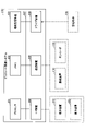
- FIG. 1 is a first diagram showing an example of a system configuration of a moving image transmission system.
- FIG. 2 is a diagram showing an example of a hardware configuration of a bit rate control system.
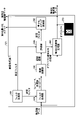
- FIG. 3 is a first diagram showing an example of the functional configuration of the image processing device.
- FIG. 4 is a diagram showing a specific example of image processing by an image processing device.
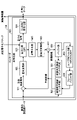
- FIG. 5 is a first diagram showing an example of the functional configuration of the control device.
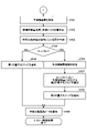
- FIG. 6 is a first flowchart showing the flow of the bit rate control process.
- FIG. 7 is a second flowchart showing the flow of the bit rate control process.
- FIG. 8 is a diagram showing a transition example of the virtual buffer position.
- FIG. 9 is a diagram showing an example of the functional configuration of the encoder.
- FIG. 9 is a diagram showing an example of the functional configuration of the encoder.
- FIG. 10 is a diagram showing details of the information amount prediction unit of the control device.
- FIG. 11 is a second diagram showing an example of the system configuration of the moving image transmission system.
- FIG. 12 is a second diagram showing an example of the functional configuration of the image processing device.
- FIG. 13 is a second diagram showing an example of the functional configuration of the control device.
- FIG. 14 is a third flowchart showing the flow of the bit rate control process.
- FIG. 1 is a first diagram showing an example of a system configuration of a moving image transmission system.
- the moving image transmission system 100 includes an image pickup device 110, a bit rate control system 120, an encoder 130, and a decoder 140.
- the encoder 130 and the decoder 140 are communicably connected via the network 150.
- the image pickup device 110 takes a picture at a predetermined frame cycle and transmits the moving image data to the bit rate control system 120. It is assumed that each frame data of the moving image data includes an object that is the target of image recognition processing by AI.
- the bit rate control system 120 has an image processing device 121 and a control device 122.
- the image processing device 121 and the control device 122 may be formed as an integrated device or as a separate device.
- the image processing device 121 identifies an object area included in the processing target frame data and an area other than the object area by performing image recognition processing on the frame data to be processed of the moving image data. .. Further, the image processing device 121 notifies the control device 122 and the encoder 130 of the invalidated moving image data in which the area other than the object area is invalidated.
- the image processing device 121 performs image recognition processing on the frame data to be processed of the moving image data while changing the image quality, so that the recognition accuracy of the object included in the frame data to be processed is the allowable limit. Identify the image quality.
- the image processing apparatus 121 calculates a first quantization step corresponding to the specified image quality. Further, the image processing device 121 notifies the control device 122 of the calculated first quantization step.
- the first quantization step corresponding to the image quality that is the allowable limit is -Of the image quality of the processed frame data generated by performing filtering etc. on the frame data to be processed, the image quality where the recognition accuracy of the object is the allowable limit and -The image quality of the decoded data generated by performing the coding process on the frame data to be processed and performing the decoding process on the coded data.
- the control device 122 measures the information amount (actual information amount) of the coded data measured when the encoder 130 performs the coding process on the frame data to be processed last time of the invalidated moving image data. Get more.
- control device 122 calculates a "virtual buffer position" indicating the remaining amount of the current virtual buffer based on the acquired actual information amount, and performs a first quantization step on the frame data to be processed. Predict the change in the virtual buffer position when the coding process is performed using.
- control device 122 determines whether or not an overflow occurs in the virtual buffer based on the prediction result of the virtual buffer position after the change. Further, when it is determined that the overflow does not occur, the control device 122 determines that the frame data to be processed is encoded by using the first quantization step.
- control device 122 determines that an overflow occurs, the control device 122 avoids the occurrence of the overflow even if the frame data to be processed is encoded under the current virtual buffer position. Calculates a possible second quantization step. In this case, the control device 122 determines to perform the coding process on the frame data to be processed by using the second quantization step.
- control device 122 notifies the encoder 130 of the quantization step (determined quantization step) determined as the quantization step used when performing the coding process on the frame data to be processed. Thereby, the control device 122 can control the encoder 130 to perform the coding process using the determination quantization step.
- the encoder 130 performs a coding process on the frame data to be processed of the invalidated moving image data by using the determination quantization step notified from the control device 122, and generates the coded data. Further, the encoder 130 transmits the generated coded data to the decoder 140 via the network 150.
- the decoder 140 performs a decoding process on the coded data transmitted from the encoder 130 and generates the decoded data.
- the decoded data generated by the decoder 140 is subjected to image recognition processing by AI (not shown).
- bit rate control system 120 -Identify the image quality at which the recognition accuracy when AI performs image recognition processing is the allowable limit. -When it is determined that overflow does not occur in the virtual buffer, the bit rate is controlled by using the first quantization step corresponding to the specified image quality.
- bit rate control system 120 According to the bit rate control system 120 according to the first embodiment, it is possible to realize bit rate control suitable for image recognition processing by AI.
- bit rate control system 120 ⁇ Hardware configuration of bit rate control system>
- the image processing device 121 and the control device 122 are formed as an integrated device.
- FIG. 2 is a diagram showing an example of the hardware configuration of the bit rate control system.
- the bit rate control system 120 includes a processor 201, a memory 202, an auxiliary storage device 203, an I / F (Interface) device 204, a communication device 205, and a drive device 206.
- the hardware of the bit rate control system 120 is connected to each other via the bus 207.
- the processor 201 has various arithmetic devices such as a CPU (Central Processing Unit) and a GPU (Graphics Processing Unit).
- the processor 201 reads various programs (for example, a bit rate control program described later) onto the memory 202 and executes them.
- the memory 202 has a main storage device such as a ROM (ReadOnlyMemory) and a RAM (RandomAccessMemory).
- the processor 201 and the memory 202 form a so-called computer, and the processor 201 realizes various functions by executing various programs read on the memory 202 (details of the various functions will be described later).
- the auxiliary storage device 203 stores various programs and various data used when various programs are executed by the processor 201.
- the I / F device 204 is a connection device that connects the operation device 210 and the display device 220, which are examples of external devices, and the bit rate control system 120.
- the I / F device 204 receives an operation on the bit rate control system 120 via the operating device 210. Further, the I / F device 204 displays the result of processing by the bit rate control system 120 via the display device 220.
- the communication device 205 is a communication device for communicating with other devices.
- the bit rate control system 120 communicates with the image pickup device 110 and the encoder 130 via the communication device 205.
- the drive device 206 is a device for setting the recording medium 230.
- the recording medium 230 referred to here includes a medium such as a CD-ROM, a flexible disk, a magneto-optical disk, or the like that optically, electrically, or magnetically records information. Further, the recording medium 230 may include a semiconductor memory or the like for electrically recording information such as a ROM or a flash memory.
- the various programs installed in the auxiliary storage device 203 are installed, for example, by setting the distributed recording medium 230 in the drive device 206 and reading the various programs recorded in the recording medium 230 by the drive device 206. Will be done.
- various programs installed in the auxiliary storage device 203 may be installed by being downloaded from the network via the communication device 205.
- FIG. 3 is a first diagram showing an example of the functional configuration of the image processing device.
- the bit rate control program is installed in the bit rate control system 120, and when the program is executed, the bit rate control system 120 has an image processing device 121.
- the filter setting unit 310 sequentially sets the setting filters having different processing intensities in the filter processing unit 320.
- What is "processing strength"? -The image quality of the frame data to be processed for moving image data and -The encoder 130 performs the coding process on the frame data to be processed by using the corresponding quantization step, and the decoder 140 performs the decoding process on the coded data to generate the decoded data.
- Image quality and It refers to the strength of the filter processing that causes the same degree of deterioration as the difference (degree of deterioration of image quality).
- the filter setting unit 310 also notifies the evaluation unit 340 of the setting filters sequentially set in the filter processing unit 320.
- the filter processing unit 320 notifies the image recognition unit 330 of the frame data to be processed among the frame data of the moving image data. Further, the filter processing unit 320 sequentially obtains the processed frame data generated by performing the filter processing on the frame data to be processed by using the setting filter sequentially set by the filter setting unit 310, in the image recognition unit 330. Notify to.
- the image recognition unit 330 has a trained model that performs image recognition processing.
- the image recognition unit 330 performs image recognition processing on the frame data to be processed notified by the filter processing unit 320, and notifies the evaluation unit 340 of the recognition result (including the recognition accuracy).
- the image recognition unit 330 performs image recognition processing on the processed frame data sequentially notified by the filter processing unit 320, and sequentially notifies the evaluation unit 340 of the recognition result (including recognition accuracy).
- the evaluation unit 340 is an example of a specific unit, and is an area of an object and an object included in the frame data to be processed based on the recognition result notified by performing the image recognition process on the frame data to be processed. Identify areas other than the area. Further, the evaluation unit 340 notifies the invalidation moving image generation unit 360 of an area other than the area of the specified object.
- the evaluation unit 340 monitors the recognition accuracy of the object included in the specified object area among the recognition results sequentially notified by performing the image recognition process on each processed frame data, and recognizes the object. Determine if the accuracy has dropped sharply.
- the evaluation unit 340 identifies the setting filter notified from the filter setting unit 310 at the timing immediately before the recognition accuracy drops sharply, and notifies the quantization step conversion unit 350.
- the quantization step conversion unit 350 is an example of the first calculation unit, and calculates the first quantization step corresponding to the setting filter specified by the evaluation unit 340.
- the quantization step conversion unit 350 notifies the control device 122 of the calculated first quantization step.
- the moving image generation unit 360 invalidates the area other than the object area for the frame data to be processed. Note that invalidating an area other than the object area means setting the pixel value of the pixel in the area other than the object area to zero among the pixels of the frame data to be processed.
- the invalidation moving image generation unit 360 notifies the control device 122 and the encoder 130 of the invalidated moving image data (for example, invalidated image data 370) generated by invalidating the frame data to be processed.
- FIG. 4 is a diagram showing a specific example of image processing by an image processing device.
- the image processing unit 330 when the filter processing unit 320 notifies the image recognition unit 330 of the frame data 400 to be processed, the image recognition unit 330 performs image recognition processing on the frame data 400 to be processed. I do.
- Reference numeral 401 indicates that the image recognition unit 330 recognizes the object by performing the image recognition processing on the frame data 400 to be processed.
- the evaluation unit 340 notifies the invalidation moving image generation unit 360 of the area other than the object area.
- the filter processing unit 320 sequentially filters the frame data 400 to be processed by using each setting filter sequentially set by the filter setting unit 310. Further, the image recognition unit 330 sequentially performs image recognition processing on the frame data after each processing.
- the filter processing unit 320 performs filter processing on the frame data 400 to be processed by using a setting filter having a processing intensity corresponding to QP 35 (setting filter corresponding to QP 35 ). It indicates that the processed frame data 410 has been generated. Further, in the example of FIG. 4, the image recognition unit 330 performs image recognition processing on the processed frame data 410 and outputs the recognition result 411, and the evaluation unit 340 sharply reduces the object recognition accuracy. It shows that it was judged.
- graph 430 shows a change in the recognition accuracy of an object when each setting filter is sequentially set in the filter processing unit 320. As shown in Graph 430, the recognition accuracy of the object is sharply lowered with the setting filter corresponding to the QP 35 as a boundary.
- the evaluation unit 340 identifies the setting filter (for example, the setting filter corresponding to the QP 34 ) notified at the timing immediately before the recognition accuracy drops sharply, and performs the quantization step conversion. Notify department 350.
- the quantization step conversion unit 350 notifies the control device 122 of the QP 34 as the first quantization step.
- FIG. 5 is a first diagram showing an example of the functional configuration of the control device.
- the bit rate control program is installed in the bit rate control system 120, and when the program is executed, the bit rate control system 120 has the control device 122.
- the information amount prediction unit 510 is an example of the prediction unit, and among the frame data of the invalidated moving image data, the frame data to be processed is encoded by using the first quantization step. Specify the amount of information (predicted information amount) of the coded data when it is performed.
- the information amount prediction unit 510 uses the statistical information amount 570 (encoding data when the image data of each attribute is coded by using each quantization step in advance. It has a table) that stores the statistical value of the information amount of the above as the predicted information amount.
- the information amount prediction unit 510 refers to the statistical information amount 570, and is the predicted information amount (statistical value) of the image data of the attribute corresponding to the attribute of the frame data to be processed, and is the first quantization step. Specify the predicted information amount (statistical value) of the quantization step corresponding to.
- the virtual buffer position calculation unit 520 calculates the current virtual buffer position based on the amount of actual information acquired from the encoder 130. Further, the virtual buffer position calculation unit 520 sets the first quantization step for the frame data to be processed based on the calculated current virtual buffer position and the predicted information amount specified by the information amount prediction unit 510. Predict the change in the virtual buffer position when the coding process is performed using.
- the overflow determination unit 530 is an example of the determination unit, and determines whether or not an overflow occurs based on the prediction result of the virtual buffer position after the change predicted by the virtual buffer position calculation unit 520. Further, the overflow determination unit 530 notifies the quantization step determination unit 560 of the first quantization step when it is determined that the overflow does not occur. When the overflow determination unit 530 determines that an overflow will occur, the overflow determination unit 530 does not notify the quantization step determination unit 560 of the first quantization step.
- the information amount candidate prediction unit 540 is a candidate for the amount of prediction information when coding processing is performed on the frame data to be processed among the frame data of the invalidated moving image data notified from the image processing device 121. To identify.
- the information amount candidate prediction unit 540 has a statistical information amount 570 in advance like the information amount prediction unit 510. Therefore, the information amount candidate prediction unit 540 refers to the statistical information amount 570 and specifies all the predicted information amount (statistical value) of the image data of the attribute corresponding to the attribute of the frame data to be processed as the predicted information amount candidate. do.
- the virtual buffer position determination unit 550 calculates the current virtual buffer position based on the amount of actual information acquired from the encoder 130. Further, the virtual buffer position determination unit 550 determines a target virtual buffer position in which overflow does not occur in the virtual buffer. Further, the virtual buffer position determination unit 550 specifies the predicted information amount corresponding to the difference between the determined target virtual buffer position and the calculated current virtual buffer position from the predicted information amount candidates. Further, the virtual buffer position determination unit 550 identifies the quantization step corresponding to the predicted information amount specified from the prediction information amount candidates as the second quantization step, and notifies the quantization step determination unit 560.
- the quantization step determination unit 560 is an example of a control unit, and when the overflow determination unit 530 notifies the first quantization step, the first quantization step is performed when the frame data to be processed is encoded. Decide to use one quantization step. Further, when the first quantization step is not notified from the overflow determination unit 530, the quantization step determination unit 560 performs the coding processing on the frame data to be processed, and the second quantum is performed. Decide to use the Quantization step.
- the quantization step determination unit 560 notifies the encoder 130 of the determined quantization step (decision quantization step).
- FIG. 6 is a first flowchart showing the flow of the bit rate control process.
- step S601 the filter processing unit 320 of the image processing device 121 acquires moving image data.
- step S602 the image recognition unit 330 of the image processing device 121 performs image recognition processing on the frame data to be processed among the frame data of the moving image data, and outputs the recognition result.
- step S603 the evaluation unit 340 of the image processing device 121 identifies an area other than the object area in the frame data to be processed based on the recognition result, and notifies the invalidation moving image generation unit 360.
- step S604 the filter setting unit 310 of the image processing device 121 sequentially sets a plurality of setting filters having different processing intensities in the filter processing unit 320 and notifies the evaluation unit 340. Further, the filter processing unit 320 of the image processing apparatus 121 sequentially performs filter processing on the frame data to be processed by using a plurality of set setting filters, and generates post-processed frame data respectively.
- step S605 the image recognition unit 330 of the image processing device 121 sequentially performs image recognition processing on each processed frame data, and outputs the recognition results.
- step S606 the evaluation unit 340 of the image processing device 121 monitors the recognition accuracy of the object among the recognition results sequentially notified from the image recognition unit 330, and determines whether the recognition accuracy of the object has dropped sharply.
- step S607 the evaluation unit 340 of the image processing device 121 identifies the setting filter notified by the filter setting unit 310 at the timing immediately before the object recognition accuracy drops sharply.
- step S608 the quantization step conversion unit 350 of the image processing apparatus 121 calculates the first quantization step, which is the quantization step corresponding to the specified setting filter.
- step S609 the invalidation moving image generation unit 360 of the image processing device 121 generates invalidation moving image data by invalidating an area other than the object area for the frame data to be processed.
- step S701 of FIG. 7 the information amount prediction unit 510 of the control device 122 performs coding processing on the frame data to be processed of the invalidated moving image data by using the first quantization step. Specify the amount of predicted information in the case of.
- step S702 the virtual buffer position calculation unit 520 of the control device 122 is the actual information amount which is the information amount of the coded data when the coding process is performed on the frame data to be processed last time by the encoder 130. And calculate the current virtual buffer position.
- step S703 when the virtual buffer position calculation unit 520 of the control device 122 performs coding processing on the frame data to be processed by using the first quantization step based on the specified predicted information amount. Predicts changes in the virtual buffer position.
- step S704 the overflow determination unit 530 of the control device 122 determines whether or not an overflow occurs based on the prediction result of the virtual buffer position after the change. If it is determined in step S704 that no overflow occurs (NO in step S704), the process proceeds to step S705.
- step S705 the overflow determination unit 530 of the control device 122 notifies the quantization step determination unit 560 of the first quantization step, and the quantization step determination unit 560 determines the first quantization step. Notify the encoder 130 as a step.
- step S704 determines whether an overflow will occur (YES in step S704). If it is determined in step S704 that an overflow will occur (YES in step S704), the process proceeds to step S706.
- step S706 the information amount candidate prediction unit 540 of the control device 122 specifies the prediction information amount candidate when the frame data to be processed of the invalidated moving image data is encoded.
- the virtual buffer position determining unit 550 of the control device 122 is the actual information amount which is the information amount of the coded data when the coded process is performed on the frame data to be processed last time by the encoder 130. And calculate the current virtual buffer position. Further, the virtual buffer position determination unit 550 of the control device 122 determines the target virtual buffer position where overflow does not occur in the virtual buffer, and specifies the predicted information amount satisfying the determined target virtual buffer position from the predicted information amount candidates. do. Further, the virtual buffer positioning unit 550 identifies a second quantization step corresponding to the specified predicted information amount.
- step S708 the virtual buffer positioning unit 550 of the control device 122 notifies the quantization step determination unit 560 of the second quantization step, and the quantization step determination unit 560 determines the second quantization step. Notify the encoder 130 as a quantization step.
- step S709 the invalidation moving image generation unit 360 of the image processing device 121 notifies the encoder 130 of the frame data to be processed among the invalidated moving image data.
- the encoder 130 can perform coding processing on the frame data to be processed of the invalidated moving image data by using the determination quantization step.
- FIG. 8 is a diagram showing a transition example of the virtual buffer position.
- the horizontal axis represents time and the vertical axis represents the amount of information of the virtual buffer seen from the encoder 130, and it is determined that overflow occurs when the predicted virtual buffer position exceeds the reference numeral 800. It represents that.
- the dotted line graph 810 shows the transition of the virtual buffer position when the conventional bit rate control process is performed.
- the coded frame data encoded data
- the coded processing is performed on the frame data n at the timing when the virtual buffer position transitions to the position indicated by the reference numeral 801.
- the coding processing is performed so that the image quality of the frame data is maintained as much as possible within the range where overflow does not occur, so that the virtual buffer position transitions to the reference numeral 811.
- the frame data n (encoded data) subjected to the coding process is transmitted, and the code processing is performed on the frame data (n + 1) at the timing when the virtual buffer position transitions to the position indicated by the reference numeral 812.
- the virtual buffer position transitions to reference numeral 813.
- the coding process is performed on the frame data (n + 2). Suppose it was done. As a result, the virtual buffer position transitions to reference numeral 815.
- the virtual buffer position changes with the passage of time within the range where overflow does not occur (see Graph 810).
- the bit rate control process is performed by the bit rate control system 120, and the first quantization step is notified by the control device 122 as the determination quantization step.
- the coded frame data encoded data
- the coded process is performed on the frame data n at the timing when the virtual buffer position transitions to the position indicated by the code 801.
- the first quantization step corresponds to the image quality at which the recognition accuracy is the allowable limit.
- the amount of information of the coded data when the coding process is performed using the first quantization step is the same as that of the coded data when the coding process is performed so that the image quality is maintained as much as possible. Less than the amount of information. As a result, the virtual buffer position transitions to reference numeral 821.
- the frame data n (encoded data) subjected to the coding process is transmitted, and the code processing is performed on the frame data (n + 1) at the timing when the virtual buffer position transitions to the position indicated by the reference numeral 822.
- the first quantization step is used. In this case, the virtual buffer position transitions to reference numeral 823.
- bit rate control system 120 As described above, according to the bit rate control system 120 according to the first embodiment, it is possible to realize bit rate control suitable for image recognition processing by AI.
- FIG. 9 is a diagram showing an example of the functional configuration of the encoder.
- a coding program is installed in the encoder 130, and when the program is executed, the encoder 130 functions as a coding unit 920.
- the coding unit 920 has a difference unit 921, an orthogonal transformation unit 922, a quantization unit 923, an entropy coding unit 924, an inverse quantization unit 925, and an inverse orthogonal transformation unit 926. Further, the coding unit 920 includes an addition unit 927, a buffer unit 928, an in-loop filter unit 929, a frame buffer unit 930, an in-screen prediction unit 931 and an inter-screen prediction unit 932.
- the difference unit 921 calculates the difference between the invalidated moving image data (for example, invalidated moving image data 370) and the predicted image data, and outputs the predicted residual signal.
- the orthogonal transformation unit 922 performs orthogonal transformation processing on the predicted residual signal output by the difference unit 921.
- the quantization unit 923 quantizes the predicted residual signal that has undergone orthogonal transformation processing, and generates a quantization signal.
- the quantization unit 923 generates a quantization signal using the determination quantization step.
- the entropy coding unit 924 generates coded data by performing an entropy coding process on the quantized signal.
- the amount of information of the generated coded data is notified to the control device 122 as the amount of actual information.
- the dequantization unit 925 dequantizes the quantization signal.
- the inverse orthogonal transformation unit 926 performs an inverse orthogonal transformation process on the inversely quantized quantized signal.
- the addition unit 927 generates reference image data by adding the signal output from the inverse orthogonal transformation unit 926 and the predicted image data.
- the buffer unit 928 stores the reference image data generated by the addition unit 927.
- the in-loop filter unit 929 performs a filter process on the reference image data stored in the buffer unit 928.
- the filter unit 929 in the loop has -Deblocking filter (DB), -Sample Adaptive Offset filter (SAO), -Adaptive loop filter (ALF), Is included.
- the frame buffer unit 930 stores the reference image data filtered by the in-loop filter unit 929 in frame units.
- the in-screen prediction unit 931 makes in-screen predictions based on the reference image data and generates predicted image data.
- the inter-screen prediction unit 932 performs motion compensation between frames using the input image data (for example, invalidated moving image data 370) and reference image data, and generates predicted image data.
- the predicted image data generated by the in-screen prediction unit 931 or the inter-screen prediction unit 932 is output to the difference unit 921 and the addition unit 927.
- the coding unit 920 uses MPEG-2, MPEG-4, H.M.
- the coding process is performed using an existing moving image coding method such as 264 or HEVC.
- the coding process by the coding unit 920 is not limited to these moving image coding methods, and may be performed by using an arbitrary moving image coding method in which the compression rate is controlled by parameters such as a quantization step.
- the bit rate control system performs image recognition processing on the frame data to be processed for moving image data while changing the image quality.
- the bit rate control system according to the first embodiment identifies the image quality at which the recognition accuracy of the object included in the frame data to be processed is the allowable limit, and the first quantization step corresponding to the specified image quality. Is calculated.
- bit rate control system predicts a change in the virtual buffer position when the code processing is performed on the frame data to be processed by using the calculated first quantization step. , Determine if overflow occurs in the virtual buffer.
- bit rate control system controls to perform coding processing on the frame to be processed by using the calculated first quantization step when it is determined that overflow does not occur. do.
- bit rate control system According to the bit rate control system according to the first embodiment, it is possible to realize bit rate control suitable for image recognition processing by AI.
- FIG. 10 is a diagram showing details of the information amount prediction unit of the control device.
- the information amount prediction unit 510 has a statistical information calculation unit 1001, a correction unit 1002, an effective domain extraction unit 1011 and a statistical information calculation unit 1012.
- the statistical information calculation unit 1001 and the correction unit 1002 specify the amount of prediction information when the coding process by inter-screen prediction (inter-prediction) is performed in the encoder 130.
- the statistical information calculation unit 1001 specifies the predicted information amount of the frame data to be processed of the invalidated moving image data based on the statistical information amount (for example, the statistical information amount 570). Further, in the correction unit 1002, among the past frame data that has been coded by inter-prediction, the coded data when the frame data that is close to the frame data to be processed is coded by inter-prediction. Correct using the amount of information (actual amount of information).
- the effective domain extraction unit 1011 and the statistical information calculation unit 1012 specify the amount of prediction information when the coding process by the in-screen prediction (intra prediction) is performed in the encoder 130.
- the effective area extraction unit 1011 extracts an object area as an effective area from the frame data to be processed of the invalidated moving image data, and notifies the statistical information calculation unit 1012 of the effective area moving image data. Further, the effective area extraction unit 1011 calculates the area of the extracted effective area and notifies the statistical information calculation unit 1012. Further, the statistical information calculation unit 1012 limits the amount of statistical information (for example, the amount of statistical information 570 to the effective area) of the frame data to be processed in the effective area moving image data while taking into account the area of the effective area. ) To specify the amount of predicted information.
- the statistical information calculation units 1001 and 1012 specify the predicted information amount by using the statistical information amount stored in advance (for example, the statistical information amount 570 and the like).
- the quantity may be updated, for example, by a learning function. Specifically, it is based on the difference between the predicted information amount specified by using the statistical information amount stored in advance and the information amount (actual information amount) of the coded data when the coding process is actually performed. , The amount of statistical information may be updated.
- inter-prediction inter-screen prediction
- intra-prediction in-screen prediction
- the frame rate is lowered to generate the overflow.
- the third embodiment will be described focusing on the differences from the first embodiment.
- FIG. 11 is a second diagram showing an example of the system configuration of the moving image transmission system.
- bit rate control system 1110 includes an image processing device 1111 and a control device 1112.
- the image processing device 1111 performs image recognition processing on the frame data to be processed of the moving image data to specify the area of the object included in the frame data to be processed and the area other than the area of the object. .. Further, the image processing device 1111 notifies the control device 1122 of the invalidated moving image data in which the area other than the object area is invalidated.
- the image processing device 1111 performs image recognition processing on the frame data to be processed of the moving image data while changing the image quality, so that the recognition accuracy of the object included in the frame data to be processed is the allowable limit. Identify the image quality.
- the image processing apparatus 1111 calculates the first quantization step corresponding to the specified image quality. Further, the image processing device 1111 notifies the control device 1112 of the calculated first quantization step.
- the image processing device 1111 outputs invalidated moving image data according to the frame rate. , Notify the encoder 130.
- the control device 1112 measures the information amount (actual information amount) of the coded data measured when the encoder 130 performs the coding process on the frame data to be processed last time of the invalidated moving image data. Get more.
- control device 1112 calculates the current virtual buffer position based on the acquired actual information amount and performs the coding process on the frame data to be processed by using the first quantization step. Predicts changes in the virtual buffer position.
- control device 1112 determines whether or not an overflow occurs in the virtual buffer based on the prediction result of the virtual buffer position after the change. Further, when the control device 1112 determines that the overflow does not occur, the control device 1112 performs the coding process on the frame data to be processed by using the first quantization step without changing the frame rate. To determine.
- control device 1112 determines that an overflow occurs, the control device 1112 calculates a frame rate capable of avoiding the occurrence of the overflow based on the calculated current virtual buffer position. Further, the control device 1112 notifies the image processing device 1111 of the calculated frame rate, and determines that the coding process is performed using the first quantization step.
- control device 1112 notifies the encoder 130 of the first quantization step as a determination quantization step. As a result, the control device 1112 can control the encoder 130 to perform the coding process on the invalidated moving image data whose frame rate has been changed by using the first quantization step.
- FIG. 12 is a second diagram showing an example of the functional configuration of the image processing device. The difference from the image processing device 121 described with reference to FIG. 3 is that it has a frame rate changing unit 1201.
- the frame rate changing unit 1201 acquires the invalidated moving image data output from the invalidated moving image generation unit 360, and thins out the frame data according to the frame rate notified from the control device 1112. Further, the frame rate changing unit 1201 notifies the encoder 130 of the invalidated moving image data obtained by thinning out the frame data according to the frame rate.
- FIG. 13 is a second diagram showing an example of the functional configuration of the control device.
- the difference from the control device 122 shown in FIG. 5 is that it has a frame rate calculation unit 1301 and that the function of the quantization step determination unit 1302 is different from the function of the quantization step determination unit 560.
- the frame rate calculation unit 1301 is an example of the second calculation unit, and when the overflow determination unit 530 determines that an overflow occurs, the frame rate that can avoid the occurrence of the overflow is calculated. Further, the frame rate calculation unit 1301 notifies the image processing device 1111 of the calculated frame rate.
- the quantization step determination unit 1302 determines the first quantization step notified by the overflow determination unit 530 as a quantization step used when performing coding processing on the frame data to be processed. Further, the quantization step determination unit 1302 notifies the encoder 130 of the determination quantization step.
- FIG. 14 is a third flowchart showing the flow of the bit rate control process. The difference from the second flowchart shown in FIG. 7 is steps S1401, S1411, and S1412.
- step S1401 the frame rate changing unit 1201 of the image processing device 1111 notifies the encoder 130 of the invalidated moving image data without changing the frame rate.
- step S1411 the overflow determination unit 530 of the control device 1122 notifies the quantization step determination unit 1302 of the first quantization step, and the quantization step determination unit 1302 notifies the encoder 130 of the first quantization step. do.
- step S1412 the frame rate calculation unit 1301 of the control device 1112 calculates a frame rate capable of avoiding the occurrence of overflow, and notifies the frame rate change unit 1201 of the image processing device 1111. Further, the frame rate changing unit 1201 of the image processing device 1111 notifies the encoder 130 of the invalidated moving image data obtained by thinning out the frame data according to the notified frame rate.
- the bit rate control system performs image recognition processing on the frame data to be processed of the moving image data while changing the image quality.
- the bit rate control system according to the third embodiment identifies the image quality at which the recognition accuracy of the object included in the frame data to be processed is the allowable limit, and the first quantization step corresponding to the specified image quality. Is calculated.
- bit rate control system predicts a change in the virtual buffer position when the code processing is performed on the frame data to be processed by using the calculated first quantization step. , Determine if overflow occurs in the virtual buffer.
- bit rate control system calculates a frame rate that can avoid the occurrence of overflow when it is determined that the overflow occurs. Further, the bit rate control system according to the third embodiment controls the invalidated moving image data according to the calculated frame rate to perform the coding process by using the calculated first quantization step. ..
- bit rate control system According to the bit rate control system according to the third embodiment, it is possible to realize bit rate control suitable for image recognition processing by AI.
- the image processing device has been described as having the invalidated moving image generation unit generate invalidated moving image data and notify the control device and the encoder.
- the image processing device may notify the control device and the encoder of the moving image data.
- the control device specifies the predicted information amount or the predicted information amount candidate based on the frame data of the moving image data.
- the encoder performs coding processing on the frame data of the moving image data.
- the frame rate changing unit 1201 does not mention the frame data thinned out from the invalidated moving image data, but the frame rate changing unit 1201 may thin out the frame data to be processed, for example. good.
- the frame data to be processed and the frame data to be processed next time may be thinned out. That is, the frame data thinned out from the invalidated moving image data is not limited to one, and may be plural.
- the occurrence of overflow is avoided by changing the frame rate and increasing the permissible value of the amount of information that can be allocated per frame, but in order to avoid the occurrence of overflow.
- the method is not limited to this, and other methods may be used.
- a plurality of methods for avoiding the occurrence of such overflow may be applied in combination.
- methods such as reducing color information or changing the resolution may be applied in combination.
- Video transmission system 120 Bit rate control system 121: Image processing device 122: Control device 130: Encoder 140: Decoder 310: Filter setting unit 320: Filter processing unit 330: Image recognition unit 340: Evaluation unit 350: Quantization Step conversion unit 360: Invalidation video generation unit 510: Information amount prediction unit 520: Virtual buffer position calculation unit 530: Overflow determination unit 540: Information amount candidate prediction unit 550: Virtual buffer position determination unit 560: Quantization step determination unit 1110: Bit rate control system 1111: Image processing device 1112: Control device 1201: Frame rate change unit 1301: Frame rate calculation unit 1302: Quantization step determination unit
Landscapes
- Engineering & Computer Science (AREA)
- Multimedia (AREA)
- Signal Processing (AREA)
- Physics & Mathematics (AREA)
- General Physics & Mathematics (AREA)
- Theoretical Computer Science (AREA)
- Quality & Reliability (AREA)
- Computer Vision & Pattern Recognition (AREA)
- Evolutionary Computation (AREA)
- Mathematical Optimization (AREA)
- Mathematical Analysis (AREA)
- Pure & Applied Mathematics (AREA)
- Algebra (AREA)
- Health & Medical Sciences (AREA)
- Artificial Intelligence (AREA)
- Computing Systems (AREA)
- Databases & Information Systems (AREA)
- General Health & Medical Sciences (AREA)
- Medical Informatics (AREA)
- Software Systems (AREA)
- Compression Or Coding Systems Of Tv Signals (AREA)
Abstract
AIによる画像認識処理に適したビットレート制御を実現する。ビットレート制御システムは、動画像の処理対象のフレームについて、画質を変更しながら画像認識処理を行うことで、前記処理対象のフレームに含まれるオブジェクトの認識精度が許容限界となる画質を特定する特定部と、特定された前記画質に対応する第1の量子化ステップを算出する第1の算出部と、算出された前記第1の量子化ステップで前記処理対象のフレームに対して符号化処理を行った場合に、仮想バッファにおいてオーバフローが発生するか否かを判定する判定部と、オーバフローが発生しないと判定された場合に、算出された前記第1の量子化ステップを用いて、前記処理対象のフレームに対して符号化処理を行うよう制御する制御部とを有する。
Description
本発明は、ビットレート制御システム、ビットレート制御方法及びビットレート制御プログラムに関する。
一般に、動画像データを符号化して伝送する場合、伝送負荷に応じて、ビットレートの制御が行われる。例えば、VBR(Variable Bit Rate)モードの場合、動画像データの各フレームデータに対して、シーンに応じたビットレートが割り当てられる。
一方で、近年、AI(Artificial Intelligence)による画像認識処理に利用される目的で、動画像データを符号化して伝送するケースが増えてきている。AIの代表的なモデルとしては、例えば、深層学習や機械学習を用いたモデルが挙げられる。
しかしながら、従来の符号化処理では、仮想バッファにおいてオーバフローが発生しない範囲で、できるだけ動画像データの画質が維持されるようにビットレートの制御が行われていた。このため、従来の符号化処理では、AIによる画像認識処理において必要でない領域について、過剰な画質で伝送される場合があった。
一つの側面では、AIによる画像認識処理に適したビットレート制御を実現することを目的とする。
一態様によれば、ビットレート制御システムは、
動画像の処理対象のフレームに対して、画質を変更しながら画像認識処理を行うことで、前記処理対象のフレームに含まれるオブジェクトの認識精度が許容限界となる画質を特定する特定部と、
特定された前記画質に対応する第1の量子化ステップを算出する第1の算出部と、
算出された前記第1の量子化ステップを用いて前記処理対象のフレームに対して符号化処理を行った場合に、仮想バッファにおいてオーバフローが発生するか否かを判定する判定部と、
オーバフローが発生しないと判定された場合に、算出された前記第1の量子化ステップを用いて、前記処理対象のフレームに対して符号化処理を行うよう制御する制御部とを有する。
動画像の処理対象のフレームに対して、画質を変更しながら画像認識処理を行うことで、前記処理対象のフレームに含まれるオブジェクトの認識精度が許容限界となる画質を特定する特定部と、
特定された前記画質に対応する第1の量子化ステップを算出する第1の算出部と、
算出された前記第1の量子化ステップを用いて前記処理対象のフレームに対して符号化処理を行った場合に、仮想バッファにおいてオーバフローが発生するか否かを判定する判定部と、
オーバフローが発生しないと判定された場合に、算出された前記第1の量子化ステップを用いて、前記処理対象のフレームに対して符号化処理を行うよう制御する制御部とを有する。
AIによる画像認識処理に適したビットレート制御を実現することができる。
以下、各実施形態について添付の図面を参照しながら説明する。なお、本明細書及び図面において、実質的に同一の機能構成を有する構成要素については、同一の符号を付することにより重複した説明を省略する。
[第1の実施形態]
<動画像伝送システムのシステム構成>
はじめに、第1の実施形態に係るビットレート制御システムを含む、動画像伝送システム全体のシステム構成について説明する。図1は、動画像伝送システムのシステム構成の一例を示す第1の図である。
<動画像伝送システムのシステム構成>
はじめに、第1の実施形態に係るビットレート制御システムを含む、動画像伝送システム全体のシステム構成について説明する。図1は、動画像伝送システムのシステム構成の一例を示す第1の図である。
図1に示すように、動画像伝送システム100は、撮像装置110、ビットレート制御システム120、エンコーダ130、デコーダ140を有する。動画像伝送システム100において、エンコーダ130とデコーダ140とは、ネットワーク150を介して通信可能に接続される。
撮像装置110は、所定のフレーム周期で撮影を行い、動画像データをビットレート制御システム120に送信する。なお、動画像データの各フレームデータには、AIによる画像認識処理の対象となるオブジェクトが含まれるものとする。
ビットレート制御システム120は、画像処理装置121と制御装置122とを有する。なお、画像処理装置121と制御装置122とは一体の装置として形成されていても、別体の装置として形成されていてもよい。
画像処理装置121は、動画像データの処理対象のフレームデータに対して、画像認識処理を行うことで、処理対象のフレームデータに含まれるオブジェクトの領域と、オブジェクトの領域以外の領域とを特定する。また、画像処理装置121は、オブジェクトの領域以外の領域を無効化した無効化動画像データを、制御装置122及びエンコーダ130に通知する。
また、画像処理装置121は、動画像データの処理対象のフレームデータに対して、画質を変更しながら画像認識処理を行うことで、処理対象のフレームデータに含まれるオブジェクトの認識精度が許容限界となる画質を特定する。また、画像処理装置121は、特定した画質に対応する第1の量子化ステップを算出する。更に、画像処理装置121は、算出した第1の量子化ステップを制御装置122に通知する。
なお、許容限界となる画質に対応する第1の量子化ステップとは、
・処理対象のフレームデータに対してフィルタ処理等を行うことで生成した処理後フレームデータの画質のうち、オブジェクトの認識精度が許容限界となる画質と、
・処理対象のフレームデータに対して符号化処理を行い、符号化データに対して復号処理を行うことで生成した復号データの画質と、
が同程度になる場合に、当該符号化処理において用いられた量子化ステップを指す。
・処理対象のフレームデータに対してフィルタ処理等を行うことで生成した処理後フレームデータの画質のうち、オブジェクトの認識精度が許容限界となる画質と、
・処理対象のフレームデータに対して符号化処理を行い、符号化データに対して復号処理を行うことで生成した復号データの画質と、
が同程度になる場合に、当該符号化処理において用いられた量子化ステップを指す。
制御装置122は、エンコーダ130が無効化動画像データの前回の処理対象のフレームデータに対して符号化処理を行った際に測定した、符号化データの情報量(実績情報量)を、エンコーダ130より取得する。
また、制御装置122は、取得した実績情報量に基づいて、現在の仮想バッファの残量を示す「仮想バッファ位置」を算出し、処理対象のフレームデータに対して、第1の量子化ステップを用いて符号化処理を行った場合の、仮想バッファ位置の変化を予測する。
また、制御装置122は、変化後の仮想バッファ位置の予測結果に基づいて、仮想バッファにおいてオーバフローが発生するか否かを判定する。また、制御装置122は、オーバフローが発生しないと判定した場合には、処理対象のフレームデータに対して第1の量子化ステップを用いて符号化処理を行うことを決定する。
また、制御装置122は、オーバフローが発生すると判定した場合には、現在の仮想バッファ位置のもとで、処理対象のフレームデータに対して符号化処理を行ったとしてもオーバフローの発生を回避することが可能な第2の量子化ステップを算出する。この場合、制御装置122は、処理対象のフレームデータに対して第2の量子化ステップを用いて符号化処理を行うことを決定する。
更に、制御装置122は、処理対象のフレームデータに対して符号化処理を行う際に用いる量子化ステップとして決定した量子化ステップ(決定量子化ステップ)を、エンコーダ130に通知する。これにより、制御装置122は、決定量子化ステップを用いて符号化処理を行うようエンコーダ130を制御することができる。
エンコーダ130は、制御装置122より通知された決定量子化ステップを用いて、無効化動画像データの処理対象のフレームデータに対して符号化処理を行い、符号化データを生成する。また、エンコーダ130は、生成した符号化データを、ネットワーク150を介してデコーダ140に伝送する。
デコーダ140は、エンコーダ130より伝送された符号化データに対して復号処理を行い、復号データを生成する。なお、デコーダ140により生成された復号データに対しては、不図示のAIにより画像認識処理が行われる。
このように、第1の実施形態に係るビットレート制御システム120では、
・AIが画像認識処理した際の認識精度が許容限界となる画質を特定し、
・仮想バッファにおいてオーバフローが発生しないと判定した場合に、当該特定した画質に対応する第1の量子化ステップを用いてビットレート制御を行う。
・AIが画像認識処理した際の認識精度が許容限界となる画質を特定し、
・仮想バッファにおいてオーバフローが発生しないと判定した場合に、当該特定した画質に対応する第1の量子化ステップを用いてビットレート制御を行う。
これにより、第1の実施形態に係るビットレート制御システム120によれば、AIによる画像認識処理に適したビットレート制御を実現することができる。
<ビットレート制御システムのハードウェア構成>
次に、ビットレート制御システム120のハードウェア構成について説明する。なお、ここでは、画像処理装置121と制御装置122とが一体の装置として形成されているものとして説明する。
次に、ビットレート制御システム120のハードウェア構成について説明する。なお、ここでは、画像処理装置121と制御装置122とが一体の装置として形成されているものとして説明する。
図2は、ビットレート制御システムのハードウェア構成の一例を示す図である。ビットレート制御システム120は、プロセッサ201、メモリ202、補助記憶装置203、I/F(Interface)装置204、通信装置205、ドライブ装置206を有する。なお、ビットレート制御システム120の各ハードウェアは、バス207を介して相互に接続されている。
プロセッサ201は、CPU(Central Processing Unit)、GPU(Graphics Processing Unit)等の各種演算デバイスを有する。プロセッサ201は、各種プログラム(例えば、後述するビットレート制御プログラム等)をメモリ202上に読み出して実行する。
メモリ202は、ROM(Read Only Memory)、RAM(Random Access Memory)等の主記憶デバイスを有する。プロセッサ201とメモリ202とは、いわゆるコンピュータを形成し、プロセッサ201が、メモリ202上に読み出した各種プログラムを実行することで、当該コンピュータは各種機能を実現する(各種機能の詳細は後述する)。
補助記憶装置203は、各種プログラムや、各種プログラムがプロセッサ201によって実行される際に用いられる各種データを格納する。
I/F装置204は、外部装置の一例である操作装置210、表示装置220と、ビットレート制御システム120とを接続する接続デバイスである。I/F装置204は、ビットレート制御システム120に対する操作を、操作装置210を介して受け付ける。また、I/F装置204は、ビットレート制御システム120による処理の結果を、表示装置220を介して表示する。
通信装置205は、他の装置と通信するための通信デバイスである。ビットレート制御システム120は、通信装置205を介して撮像装置110及びエンコーダ130と通信する。
ドライブ装置206は記録媒体230をセットするためのデバイスである。ここでいう記録媒体230には、CD-ROM、フレキシブルディスク、光磁気ディスク等のように情報を光学的、電気的あるいは磁気的に記録する媒体が含まれる。また、記録媒体230には、ROM、フラッシュメモリ等のように情報を電気的に記録する半導体メモリ等が含まれていてもよい。
なお、補助記憶装置203にインストールされる各種プログラムは、例えば、配布された記録媒体230がドライブ装置206にセットされ、該記録媒体230に記録された各種プログラムがドライブ装置206により読み出されることでインストールされる。あるいは、補助記憶装置203にインストールされる各種プログラムは、通信装置205を介してネットワークからダウンロードされることで、インストールされてもよい。
<画像処理装置の機能構成>
次に、ビットレート制御システム120のうち、画像処理装置121の機能構成について説明する。図3は、画像処理装置の機能構成の一例を示す第1の図である。上述したように、ビットレート制御システム120には、ビットレート制御プログラムがインストールされており、当該プログラムが実行されることで、ビットレート制御システム120は、画像処理装置121が、
・フィルタ設定部310、
・フィルタ処理部320、
・画像認識部330、
・評価部340、
・量子化ステップ変換部350、
・無効化動画像生成部360、
として機能する。
次に、ビットレート制御システム120のうち、画像処理装置121の機能構成について説明する。図3は、画像処理装置の機能構成の一例を示す第1の図である。上述したように、ビットレート制御システム120には、ビットレート制御プログラムがインストールされており、当該プログラムが実行されることで、ビットレート制御システム120は、画像処理装置121が、
・フィルタ設定部310、
・フィルタ処理部320、
・画像認識部330、
・評価部340、
・量子化ステップ変換部350、
・無効化動画像生成部360、
として機能する。
このうち、フィルタ設定部310は、処理強度の異なる設定フィルタを、順次、フィルタ処理部320に設定する。「処理強度」とは、
・動画像データの処理対象のフレームデータの画質と、
・エンコーダ130が、対応する量子化ステップを用いて、当該処理対象のフレームデータに対して符号化処理を行い、デコーダ140が、符号化データに対して復号処理を行うことで生成した復号データの画質と、
の差(画質の劣化度合い)と同等の劣化度合いを生じさせるフィルタ処理の強度を指す。
・動画像データの処理対象のフレームデータの画質と、
・エンコーダ130が、対応する量子化ステップを用いて、当該処理対象のフレームデータに対して符号化処理を行い、デコーダ140が、符号化データに対して復号処理を行うことで生成した復号データの画質と、
の差(画質の劣化度合い)と同等の劣化度合いを生じさせるフィルタ処理の強度を指す。
また、フィルタ設定部310は、フィルタ処理部320に順次設定した設定フィルタを、評価部340にも通知する。
フィルタ処理部320は、動画像データの各フレームデータのうち、処理対象のフレームデータを画像認識部330に通知する。また、フィルタ処理部320は、フィルタ設定部310より順次設定される設定フィルタを用いて、処理対象のフレームデータに対してフィルタ処理を行うことで生成した処理後フレームデータを、順次画像認識部330に通知する。
画像認識部330は、画像認識処理を行う学習済みモデルを有する。画像認識部330は、フィルタ処理部320より通知される処理対象のフレームデータに対して画像認識処理を行い、認識結果(認識精度を含む)を評価部340に通知する。
また、画像認識部330は、フィルタ処理部320より順次通知される処理後フレームデータに対して画像認識処理を行い、認識結果(認識精度を含む)を順次評価部340に通知する。
評価部340は特定部の一例であり、処理対象のフレームデータに対して画像認識処理が行われることで通知された認識結果に基づいて、処理対象のフレームデータに含まれるオブジェクトの領域及びオブジェクトの領域以外の領域を特定する。また、評価部340は、特定したオブジェクトの領域以外の領域を無効化動画像生成部360に通知する。
また、評価部340は、各処理後フレームデータに対して画像認識処理が行われることで順次通知される認識結果のうち、特定したオブジェクト領域に含まれるオブジェクトの認識精度を監視し、オブジェクトの認識精度が急激に低下したか否かを判定する。
また、評価部340は、認識精度が急激に低下した直前のタイミングで、フィルタ設定部310から通知された設定フィルタを特定し、量子化ステップ変換部350に通知する。
量子化ステップ変換部350は第1の算出部の一例であり、評価部340により特定された設定フィルタに対応する第1の量子化ステップを算出する。
また、量子化ステップ変換部350は、算出した第1の量子化ステップを制御装置122に通知する。
無効化動画像生成部360は、処理対象のフレームデータについてオブジェクト領域以外の領域を無効化する。なお、オブジェクト領域以外の領域を無効化するとは、処理対象のフレームデータの各画素のうち、オブジェクト領域以外の領域の画素の画素値を、ゼロにすることを指す。
無効化動画像生成部360は、処理対象のフレームデータを無効化することで生成した無効化動画像データ(例えば、無効化画像データ370)を、制御装置122及びエンコーダ130に通知する。
<画像処理装置による画像処理の具体例>
次に、画像処理装置121による画像処理の具体例について説明する。図4は、画像処理装置による画像処理の具体例を示す図である。
次に、画像処理装置121による画像処理の具体例について説明する。図4は、画像処理装置による画像処理の具体例を示す図である。
図4に示すように、画像処理装置121では、フィルタ処理部320が処理対象のフレームデータ400を画像認識部330に通知すると、画像認識部330が処理対象のフレームデータ400に対して画像認識処理を行う。符号401は、画像認識部330が処理対象のフレームデータ400に対して画像認識処理を行ったことで、オブジェクトを認識した様子を示している。これにより、評価部340では、オブジェクト領域以外の領域を無効化動画像生成部360に通知する。
また、上述したように、画像処理装置121では、フィルタ処理部320が、フィルタ設定部310により順次設定された各設定フィルタを用いて、処理対象のフレームデータ400に対して順次フィルタ処理を行う。また、画像認識部330が、各処理後フレームデータに対して順次画像認識処理を行う。
図4の例は、QP35に相当する処理強度を有する設定フィルタ(QP35に対応する設定フィルタ)を用いて、フィルタ処理部320が、処理対象のフレームデータ400に対してフィルタ処理を行い、処理後フレームデータ410を生成したことを示している。また、図4の例は、処理後フレームデータ410に対して、画像認識部330が画像認識処理を行い、認識結果411を出力するとともに、評価部340が、オブジェクトの認識精度が急激に低下したと判定したことを示している。
なお、図4において、グラフ430は、フィルタ処理部320に各設定フィルタが順次設定された際の、オブジェクトの認識精度の変化を示している。グラフ430に示すように、オブジェクトの認識精度は、QP35に対応する設定フィルタを境に認識精度が急激に低下している。
このため、図4の例の場合、評価部340は、認識精度が急激に低下した直前のタイミングで通知された設定フィルタ(例えば、QP34に対応する設定フィルタ)を特定し、量子化ステップ変換部350に通知する。
この結果、図4に示すように、量子化ステップ変換部350では、第1の量子化ステップとして、QP34を制御装置122に通知する。
<制御装置の機能構成>
次に、ビットレート制御システム120のうち、制御装置122の機能構成について説明する。図5は、制御装置の機能構成の一例を示す第1の図である。上述したように、ビットレート制御システム120には、ビットレート制御プログラムがインストールされており、当該プログラムが実行されることで、ビットレート制御システム120は、制御装置122が、
・情報量予測部510、
・仮想バッファ位置算出部520、
・オーバフロー判定部530、
・情報量候補予測部540、
・仮想バッファ位置決定部550、
・量子化ステップ決定部560、
として機能する。
次に、ビットレート制御システム120のうち、制御装置122の機能構成について説明する。図5は、制御装置の機能構成の一例を示す第1の図である。上述したように、ビットレート制御システム120には、ビットレート制御プログラムがインストールされており、当該プログラムが実行されることで、ビットレート制御システム120は、制御装置122が、
・情報量予測部510、
・仮想バッファ位置算出部520、
・オーバフロー判定部530、
・情報量候補予測部540、
・仮想バッファ位置決定部550、
・量子化ステップ決定部560、
として機能する。
このうち、情報量予測部510は予測部の一例であり、無効化動画像データの各フレームデータのうち、処理対象のフレームデータに対して、第1の量子化ステップを用いて符号化処理が行われた場合の符号化データの情報量(予測情報量)を特定する。
なお、図5に示すように、情報量予測部510は、予め統計情報量570(各属性の画像データに対して、それぞれの量子化ステップを用いて符号化処理を行った場合の符号化データの情報量の統計値を予測情報量として格納したテーブル)を有している。
このため、情報量予測部510は、統計情報量570を参照し、処理対象のフレームデータの属性に対応する属性の画像データの予測情報量(統計値)であって、第1の量子化ステップに対応する量子化ステップの予測情報量(統計値)を特定する。
仮想バッファ位置算出部520は、エンコーダ130より取得した実績情報量に基づいて、現在の仮想バッファ位置を算出する。また、仮想バッファ位置算出部520は、算出した現在の仮想バッファ位置と、情報量予測部510により特定された予測情報量とに基づいて、処理対象のフレームデータに対して第1の量子化ステップを用いて符号化処理を行った場合の、仮想バッファ位置の変化を予測する。
オーバフロー判定部530は判定部の一例であり、仮想バッファ位置算出部520により予測された、変化後の仮想バッファ位置の予測結果に基づいて、オーバフローが発生するか否かを判定する。また、オーバフロー判定部530は、オーバフローが発生しないと判定した場合に、第1の量子化ステップを、量子化ステップ決定部560に通知する。なお、オーバフロー判定部530は、オーバフローが発生すると判定した場合には、第1の量子化ステップを量子化ステップ決定部560に通知しない。
情報量候補予測部540は、画像処理装置121より通知される無効化動画像データの各フレームデータのうち、処理対象のフレームデータに対して符号化処理が行われた場合の予測情報量の候補を特定する。
なお、図5に示すように、情報量候補予測部540は、情報量予測部510同様、予め統計情報量570を有している。このため、情報量候補予測部540は、統計情報量570を参照し、処理対象のフレームデータの属性に対応する属性の画像データの予測情報量(統計値)全てを、予測情報量候補として特定する。
仮想バッファ位置決定部550は、エンコーダ130より取得した実績情報量に基づいて、現在の仮想バッファ位置を算出する。また、仮想バッファ位置決定部550は、仮想バッファにおいてオーバフローが発生しない目標仮想バッファ位置を決定する。また、仮想バッファ位置決定部550は、決定した目標仮想バッファ位置と、算出した現在の仮想バッファ位置との差分に相当する予測情報量を、予測情報量候補の中から特定する。更に、仮想バッファ位置決定部550は、予測情報量候補の中から特定した予測情報量に対応する量子化ステップを、第2の量子化ステップとして特定し、量子化ステップ決定部560に通知する。
量子化ステップ決定部560は制御部の一例であり、オーバフロー判定部530より第1の量子化ステップが通知された場合には、処理対象のフレームデータに対して符号化処理を行う際に、第1の量子化ステップを用いることを決定する。また、量子化ステップ決定部560は、オーバフロー判定部530より第1の量子化ステップが通知されなかった場合には、処理対象のフレームデータに対して符号化処理を行う際に、第2の量子化ステップを用いることを決定する。
更に、量子化ステップ決定部560は、決定した量子化ステップ(決定量子化ステップ)を、エンコーダ130に通知する。
<ビットレート制御処理の流れ>
次に、ビットレート制御システム120によるビットレート制御処理の流れについて説明する。図6は、ビットレート制御処理の流れを示す第1のフローチャートである。
次に、ビットレート制御システム120によるビットレート制御処理の流れについて説明する。図6は、ビットレート制御処理の流れを示す第1のフローチャートである。
ステップS601において、画像処理装置121のフィルタ処理部320は、動画像データを取得する。
ステップS602において、画像処理装置121の画像認識部330は、動画像データの各フレームデータのうち、処理対象のフレームデータに対して画像認識処理を行い、認識結果を出力する。
ステップS603において、画像処理装置121の評価部340は、認識結果に基づいて、処理対象のフレームデータのうち、オブジェクト領域以外の領域を特定し、無効化動画像生成部360に通知する。
ステップS604において、画像処理装置121のフィルタ設定部310は、処理強度の異なる複数の設定フィルタを、順次フィルタ処理部320に設定するとともに、評価部340に通知する。また、画像処理装置121のフィルタ処理部320は、設定された複数の設定フィルタを用いて、処理対象のフレームデータに対して順次フィルタ処理を行い、処理後フレームデータをそれぞれ生成する。
ステップS605において、画像処理装置121の画像認識部330は、各処理後フレームデータに対して、順次、画像認識処理を行い、認識結果をそれぞれ出力する。
ステップS606において、画像処理装置121の評価部340は、画像認識部330から順次通知される認識結果のうち、オブジェクトの認識精度を監視し、オブジェクトの認識精度が急激に低下したかを判定する。
ステップS607において、画像処理装置121の評価部340は、オブジェクトの認識精度が急激に低下した直前のタイミングで、フィルタ設定部310から通知された設定フィルタを特定する。
ステップS608において、画像処理装置121の量子化ステップ変換部350は、特定された設定フィルタに対応する量子化ステップである、第1の量子化ステップを算出する。
ステップS609において、画像処理装置121の無効化動画像生成部360は、処理対象のフレームデータについて、オブジェクト領域以外の領域を無効化することで、無効化動画像データを生成する。
続いて、図7のステップS701において、制御装置122の情報量予測部510は、無効化動画像データの処理対象のフレームデータに対して、第1の量子化ステップを用いて符号化処理を行った場合の予測情報量を特定する。
ステップS702において、制御装置122の仮想バッファ位置算出部520は、エンコーダ130より、前回の処理対象のフレームデータに対して符号化処理が行われた際の符号化データの情報量である実績情報量を取得し、現在の仮想バッファ位置を算出する。
ステップS703において、制御装置122の仮想バッファ位置算出部520は、特定された予測情報量に基づいて、処理対象のフレームデータに対して第1の量子化ステップを用いて符号化処理を行った場合の、仮想バッファ位置の変化を予測する。
ステップS704において、制御装置122のオーバフロー判定部530は、変化後の仮想バッファ位置の予測結果に基づいて、オーバフローが発生するか否かを判定する。ステップS704において、オーバフローが発生しないと判定された場合には(ステップS704においてNOの場合には)、ステップS705に進む。
ステップS705において、制御装置122のオーバフロー判定部530は、第1の量子化ステップを量子化ステップ決定部560に通知し、量子化ステップ決定部560は、第1の量子化ステップを、決定量子化ステップとしてエンコーダ130に通知する。
一方、ステップS704において、オーバフローが発生すると判定された場合には(ステップS704においてYESの場合には)、ステップS706に進む。
ステップS706において、制御装置122の情報量候補予測部540は、無効化動画像データの処理対象のフレームデータに対して符号化処理を行った場合の予測情報量候補を特定する。
ステップS707において、制御装置122の仮想バッファ位置決定部550は、エンコーダ130より、前回の処理対象のフレームデータに対して符号化処理が行われた際の符号化データの情報量である実績情報量を取得し、現在の仮想バッファ位置を算出する。また、制御装置122の仮想バッファ位置決定部550は、仮想バッファにおいてオーバフローが発生しない目標仮想バッファ位置を決定し、予測情報量候補の中から、決定した目標仮想バッファ位置を満たす予測情報量を特定する。更に、仮想バッファ位置決定部550は、特定した予測情報量に対応する第2の量子化ステップを特定する。
ステップS708において、制御装置122の仮想バッファ位置決定部550は、第2の量子化ステップを量子化ステップ決定部560に通知し、量子化ステップ決定部560は、第2の量子化ステップを、決定量子化ステップとしてエンコーダ130に通知する。
ステップS709において、画像処理装置121の無効化動画像生成部360は、無効化動画像データのうち、処理対象のフレームデータを、エンコーダ130に通知する。
これにより、エンコーダ130では、無効化動画像データの処理対象のフレームデータに対して、決定量子化ステップを用いて符号化処理を行うことができる。
<仮想バッファ位置の遷移例>
次に、ビットレート制御システム120によりビットレート制御処理が行われることで遷移する、仮想バッファ位置の遷移例について説明する。図8は、仮想バッファ位置の遷移例を示す図である。図8において、横軸は時間を表し、縦軸はエンコーダ130から見た仮想バッファの情報量を表しており、予測される仮想バッファ位置が符号800を超えた場合に、オーバフローが発生すると判定されることを表している。
次に、ビットレート制御システム120によりビットレート制御処理が行われることで遷移する、仮想バッファ位置の遷移例について説明する。図8は、仮想バッファ位置の遷移例を示す図である。図8において、横軸は時間を表し、縦軸はエンコーダ130から見た仮想バッファの情報量を表しており、予測される仮想バッファ位置が符号800を超えた場合に、オーバフローが発生すると判定されることを表している。
図8に示すグラフのうち、点線グラフ810は、従来のビットレート制御処理が行われた場合の、仮想バッファ位置の遷移を表している。点線グラフ810に示すように、符号化処理が行われたフレームデータ(符号化データ)が伝送され、仮想バッファ位置が符号801に示す位置まで遷移したタイミングで、フレームデータnに対して符号化処理が行われたとする。上述したように、従来のビットレート制御処理では、オーバフローが発生しない範囲で、できるだけフレームデータの画質が維持されるように符号化処理が行われるため、仮想バッファ位置は符号811まで遷移する。
また、符号化処理が行われたフレームデータn(符号化データ)が伝送され、仮想バッファ位置が符号812に示す位置まで遷移したタイミングで、フレームデータ(n+1)に対して符号化処理が行われたとする。これにより、仮想バッファ位置は符号813まで遷移する。
また、符号化処理が行われたフレームデータ(n+1)(符号化データ)が伝送され、仮想バッファ位置が符号814に示す位置まで遷移したタイミングで、フレームデータ(n+2)に対して符号化処理が行われたとする。これにより、仮想バッファ位置は符号815まで遷移する。
以下、同様の処理が繰り返されることで、従来のビットレート制御処理の場合、時間の経過とともに、オーバフローが発生しない範囲で、仮想バッファ位置が遷移する(グラフ810参照)。
一方、図8に示すグラフのうち、実線グラフ820は、ビットレート制御システム120によりビットレート制御処理が行われ、第1の量子化ステップが決定量子化ステップとして制御装置122より通知された場合の、仮想バッファ位置の遷移を表している。実線グラフ820に示すように、符号化処理が行われたフレームデータ(符号化データ)が伝送され、仮想バッファ位置が符号801に示す位置まで遷移したタイミングで、フレームデータnに対して符号化処理が行われたとする。上述したように、第1の量子化ステップは、認識精度が許容限界となる画質に対応している。このため、第1の量子化ステップを用いて符号化処理が行われた場合の符号化データの情報量は、できるだけ画質が維持されるように符号化処理が行われた場合の符号化データの情報量よりも少ない。この結果、仮想バッファ位置は符号821に遷移する。
また、符号化処理が行われたフレームデータn(符号化データ)が伝送され、仮想バッファ位置が符号822に示す位置まで遷移したタイミングで、フレームデータ(n+1)に対して符号化処理が行われたとする。なお、ここでも、第1の量子化ステップを用いられたとする。この場合、仮想バッファ位置は符号823に遷移する。
また、符号化処理が行われたフレームデータ(n+1)(符号化データ)が伝送され、仮想バッファ位置が符号824に示す位置まで遷移したタイミングで、フレームデータ(n+2)に対して符号化処理が行われたとする。なお、ここでも、第1の量子化ステップが用いられたとする。この場合、仮想バッファ位置は符号825に遷移する。
以下、同様の処理が繰り返されることで、ビットレート制御システム120によるビットレート制御処理の場合、時間の経過とともに、仮想バッファ位置が低い状態のまま遷移する(グラフ820参照)。
このように、第1の実施形態に係るビットレート制御システム120によれば、AIによる画像認識処理に適したビットレート制御を実現することができる。
<エンコーダの機能構成>
次に、エンコーダ130の機能構成について説明する。図9は、エンコーダの機能構成の一例を示す図である。エンコーダ130には、符号化プログラムがインストールされており、当該プログラムが実行されることで、エンコーダ130は、符号化部920として機能する。
次に、エンコーダ130の機能構成について説明する。図9は、エンコーダの機能構成の一例を示す図である。エンコーダ130には、符号化プログラムがインストールされており、当該プログラムが実行されることで、エンコーダ130は、符号化部920として機能する。
符号化部920は、差分部921、直交変換部922、量子化部923、エントロピ符号化部924、逆量子化部925、逆直交変換部926を有する。また、符号化部920は、加算部927、バッファ部928、ループ内フィルタ部929、フレームバッファ部930、画面内予測部931、画面間予測部932を有する。
差分部921は、無効化動画像データ(例えば、無効化動画像データ370)と予測画像データとの差分を算出し、予測残差信号を出力する。
直交変換部922は、差分部921により出力された予測残差信号に対して、直交変換処理を行う。
量子化部923は、直交変換処理が行われた予測残差信号を量子化し、量子化信号を生成する。量子化部923は、決定量子化ステップを用いて量子化信号を生成する。
エントロピ符号化部924は、量子化信号に対してエントロピ符号化処理を行うことで、符号化データを生成する。なお、生成した符号化データの情報量は、実績情報量として、制御装置122に通知される。
逆量子化部925は、量子化信号を逆量子化する。逆直交変換部926は、逆量子化された量子化信号に対して、逆直交変換処理を行う。
加算部927は、逆直交変換部926より出力された信号と、予測画像データとを加算することで、参照画像データを生成する。バッファ部928は、加算部927により生成された参照画像データを格納する。
ループ内フィルタ部929は、バッファ部928に格納された参照画像データに対してフィルタ処理を行う。ループ内フィルタ部929には、
・デブロッキングフィルタ(Deblocking filter:DB)、
・サンプルアダプティブオフセットフィルタ(Sample Adaptive Offset filter:SAO)、
・適応ループフィルタ(Adaptive loop filter:ALF)、
が含まれる。
・デブロッキングフィルタ(Deblocking filter:DB)、
・サンプルアダプティブオフセットフィルタ(Sample Adaptive Offset filter:SAO)、
・適応ループフィルタ(Adaptive loop filter:ALF)、
が含まれる。
フレームバッファ部930は、ループ内フィルタ部929によりフィルタ処理が行われた参照画像データをフレーム単位で格納する。
画面内予測部931は、参照画像データに基づいて画面内予測を行い、予測画像データを生成する。画面間予測部932は、入力された画像データ(例えば、無効化動画像データ370)と参照画像データとを用いてフレーム間で動き補償を行い、予測画像データを生成する。
なお、画面内予測部931または画面間予測部932により生成された予測画像データは、差分部921及び加算部927に出力される。
なお、上記説明では、符号化部920が、MPEG-2、MPEG-4、H.264、HEVCなどの既存の動画符号化方式を用いて符号化処理を行うものとした。しかしながら、符号化部920による符号化処理は、これらの動画符号化方式に限定されず、量子化ステップ等のパラメータにより圧縮率を制御する任意の動画符号化方式を用いて行われてもよい。
以上の説明から明らかなように、第1の実施形態に係るビットレート制御システムは、動画像データの処理対象のフレームデータに対して、画質を変更しながら画像認識処理を行う。これにより、第1の実施形態に係るビットレート制御システムは、処理対象のフレームデータに含まれるオブジェクトの認識精度が許容限界となる画質を特定し、特定した画質に対応する第1の量子化ステップを算出する。
また、第1の実施形態に係るビットレート制御システムは、算出した第1の量子化ステップを用いて処理対象のフレームデータに対して符号化処理を行った場合の仮想バッファ位置の変化を予測し、仮想バッファにおいてオーバフローが発生するか否かを判定する。
更に、第1の実施形態に係るビットレート制御システムは、オーバフローが発生しないと判定した場合に、算出した第1の量子化ステップを用いて処理対象のフレームに対して符号化処理を行うよう制御する。
この結果、第1の実施形態に係るビットレート制御システムによれば、AIによる画像認識処理に適したビットレート制御を実現することができる。
[第2の実施形態]
上記第1の実施形態では、制御装置122の情報量予測部510の詳細について言及しなかった。これに対して、第2の実施形態では、情報量予測部の詳細について説明する。
上記第1の実施形態では、制御装置122の情報量予測部510の詳細について言及しなかった。これに対して、第2の実施形態では、情報量予測部の詳細について説明する。
図10は、制御装置の情報量予測部の詳細を示す図である。図10に示すように、情報量予測部510は、統計情報算出部1001、補正部1002、有効領域抽出部1011、統計情報算出部1012を有する。
統計情報算出部1001及び補正部1002は、エンコーダ130において画面間予測(インタ予測)による符号化処理が行われる場合の予測情報量を特定する。
具体的には、統計情報算出部1001は、無効化動画像データの処理対象のフレームデータについて、統計情報量(例えば、統計情報量570)に基づいて予測情報量を特定する。また、補正部1002は、インタ予測による符号化処理が行われた過去のフレームデータのうち、処理対象のフレームデータに近いフレームデータについてインタ予測による符号化処理が行われた際の符号化データの情報量(実績情報量)を用いて補正する。
一方、有効領域抽出部1011及び統計情報算出部1012は、エンコーダ130において画面内予測(イントラ予測)による符号化処理が行われる場合の予測情報量を特定する。
具体的には、有効領域抽出部1011は、無効化動画像データの処理対象のフレームデータから、オブジェクト領域を有効領域として抽出し、有効領域動画像データを統計情報算出部1012に通知する。また、有効領域抽出部1011は、抽出した有効領域の面積を算出し、統計情報算出部1012に通知する。また、統計情報算出部1012は、有効領域動画像データのうち、処理対象のフレームデータについて、有効領域の面積を加味しながら、統計情報量(例えば、統計情報量570を有効領域に限定したもの)に基づいて予測情報量を特定する。
なお、第2の実施形態において、統計情報算出部1001、1012は、予め格納された統計情報量(例えば、統計情報量570等)を用いて予測情報量を特定するものとしたが、統計情報量は、例えば、学習機能により更新されてもよい。具体的には、予め格納された統計情報量を用いて特定した予測情報量と、実際に符号化処理が行われた際の符号化データの情報量(実績情報量)との差分に基づいて、統計情報量を更新してもよい。
また、第2の実施形態では、画面間予測(インタ予測)による符号化処理が行われるフレームデータと、画面内予測(イントラ予測)による符号化処理が行われるフレームデータとで、異なる処理が行われるものとして説明した。
しかしながら、インタ予測による符号化処理が行われるフレームデータにおいて新たなオブジェクトが出現した場合には、当該新たなオブジェクトの領域について、イントラ予測による符号化処理が行われるフレームデータと同様の処理が行われてもよい。
[第3の実施形態]
上記第1の実施形態では、第1の量子化ステップを用いて符号化処理を行うことで、オーバフローが発生すると判定した場合には、第2の量子化ステップを用いて符号化処理を行うことで、オーバフローの発生を回避するものとして説明した。
上記第1の実施形態では、第1の量子化ステップを用いて符号化処理を行うことで、オーバフローが発生すると判定した場合には、第2の量子化ステップを用いて符号化処理を行うことで、オーバフローの発生を回避するものとして説明した。
これに対して、第3の実施形態では、第1の量子化ステップを用いて符号化処理を行うことで、オーバフローが発生すると判定した場合には、フレームレートを下げることで、オーバフローの発生を回避する。以下、第3の実施形態について、上記第1の実施形態との相違点を中心に説明する。
<動画像伝送システムのシステム構成>
はじめに、第3の実施形態に係るビットレート制御システムを含む、動画像伝送システム全体のシステム構成について説明する。図11は、動画像伝送システムのシステム構成の一例を示す第2の図である。
はじめに、第3の実施形態に係るビットレート制御システムを含む、動画像伝送システム全体のシステム構成について説明する。図11は、動画像伝送システムのシステム構成の一例を示す第2の図である。
図1との相違点は、ビットレート制御システム1110の機能が、ビットレート制御システム120の機能とは異なる点である。図11に示すように、ビットレート制御システム1110は、画像処理装置1111、制御装置1112を有する。
画像処理装置1111は、動画像データの処理対象のフレームデータに対して、画像認識処理を行うことで、処理対象のフレームデータに含まれるオブジェクトの領域と、オブジェクトの領域以外の領域とを特定する。また、画像処理装置1111は、オブジェクトの領域以外の領域を無効化した無効化動画像データを、制御装置1122に通知する。
また、画像処理装置1111は、動画像データの処理対象のフレームデータに対して、画質を変更しながら画像認識処理を行うことで、処理対象のフレームデータに含まれるオブジェクトの認識精度が許容限界となる画質を特定する。また、画像処理装置1111は、特定した画質に対応する第1の量子化ステップを算出する。更に、画像処理装置1111は、算出した第1の量子化ステップを制御装置1112に通知する。
また、画像処理装置1111は、第1の量子化ステップを制御装置1112に通知したことに応じて、制御装置1112よりフレームレートが通知された場合、当該フレームレートに応じた無効化動画像データを、エンコーダ130に通知する。
制御装置1112は、エンコーダ130が無効化動画像データの前回の処理対象のフレームデータに対して符号化処理を行った際に測定した、符号化データの情報量(実績情報量)を、エンコーダ130より取得する。
また、制御装置1112は、取得した実績情報量に基づいて、現在の仮想バッファ位置を算出し、処理対象のフレームデータに対して、第1の量子化ステップを用いて符号化処理を行った場合の、仮想バッファ位置の変化を予測する。
また、制御装置1112は、変化後の仮想バッファ位置の予測結果に基づいて、仮想バッファにおいてオーバフローが発生するか否かを判定する。また、制御装置1112は、オーバフローが発生しないと判定した場合には、フレームレートを変更することなく、処理対象のフレームデータに対して、第1の量子化ステップを用いて符号化処理を行うことを決定する。
また、制御装置1112は、オーバフローが発生すると判定した場合には、算出した現在の仮想バッファ位置のもとで、オーバフローの発生を回避することが可能なフレームレートを算出する。また、制御装置1112は、算出したフレームレートを、画像処理装置1111に通知するとともに、第1の量子化ステップを用いて符号化処理を行うことを決定する。
更に、制御装置1112は、第1の量子化ステップを、決定量子化ステップとして、エンコーダ130に通知する。これにより、制御装置1112は、フレームレートが変更された無効化動画像データに対して、第1の量子化ステップを用いて符号化処理を行うようエンコーダ130を制御することができる。
<画像処理装置の機能構成>
次に、ビットレート制御システム1110のうち、画像処理装置1111の機能構成について説明する。図12は、画像処理装置の機能構成の一例を示す第2の図である。図3を用いて説明した画像処理装置121との相違点は、フレームレート変更部1201を有する点である。
次に、ビットレート制御システム1110のうち、画像処理装置1111の機能構成について説明する。図12は、画像処理装置の機能構成の一例を示す第2の図である。図3を用いて説明した画像処理装置121との相違点は、フレームレート変更部1201を有する点である。
フレームレート変更部1201は、無効化動画像生成部360から出力される無効化動画像データを取得し、制御装置1112より通知されたフレームレートに従って、フレームデータを間引く。また、フレームレート変更部1201は、フレームレートに従ってフレームデータを間引いた無効化動画像データを、エンコーダ130に通知する。
<制御装置の機能構成>
次に、ビットレート制御システム1110のうち、制御装置1112の機能構成について説明する。図13は、制御装置の機能構成の一例を示す第2の図である。図5に示した制御装置122との相違点は、フレームレート算出部1301を有する点と、量子化ステップ決定部1302の機能が量子化ステップ決定部560の機能とは異なる点である。
次に、ビットレート制御システム1110のうち、制御装置1112の機能構成について説明する。図13は、制御装置の機能構成の一例を示す第2の図である。図5に示した制御装置122との相違点は、フレームレート算出部1301を有する点と、量子化ステップ決定部1302の機能が量子化ステップ決定部560の機能とは異なる点である。
フレームレート算出部1301は第2の算出部の一例であり、オーバフロー判定部530において、オーバフローが発生すると判定された場合に、オーバフローの発生を回避することが可能なフレームレートを算出する。また、フレームレート算出部1301は、算出したフレームレートを、画像処理装置1111に通知する。
量子化ステップ決定部1302は、オーバフロー判定部530より通知される第1の量子化ステップを、処理対象のフレームデータに対して符号化処理を行う際に用いる量子化ステップとして決定する。また、量子化ステップ決定部1302は、決定量子化ステップをエンコーダ130に通知する。
<ビットレート制御処理の流れ>
次に、ビットレート制御システム1110によるビットレート制御処理の流れについて説明する。ビットレート制御システム1110では、図6及び図7に示すフローチャートに代えて、図6及び図14に示すフローチャートを実行する。そこで、以下では、図14に示すフローチャートについて説明する。
次に、ビットレート制御システム1110によるビットレート制御処理の流れについて説明する。ビットレート制御システム1110では、図6及び図7に示すフローチャートに代えて、図6及び図14に示すフローチャートを実行する。そこで、以下では、図14に示すフローチャートについて説明する。
図14は、ビットレート制御処理の流れを示す第3のフローチャートである。なお、図7に示した第2のフローチャートとの相違点は、ステップS1401、S1411、S1412である。
ステップS1401において、画像処理装置1111のフレームレート変更部1201は、フレームレートを変更することなく、無効化動画像データをエンコーダ130に通知する。
ステップS1411において、制御装置1122のオーバフロー判定部530は、第1の量子化ステップを量子化ステップ決定部1302に通知し、量子化ステップ決定部1302は、第1の量子化ステップをエンコーダ130に通知する。
ステップS1412において、制御装置1112のフレームレート算出部1301は、オーバフローの発生を回避することが可能なフレームレートを算出し、画像処理装置1111のフレームレート変更部1201に通知する。また、画像処理装置1111のフレームレート変更部1201は、通知されたフレームレートに従ってフレームデータを間引いた無効化動画像データを、エンコーダ130に通知する。
以上の説明から明らかなように、第3の実施形態に係るビットレート制御システムは、動画像データの処理対象のフレームデータに対して、画質を変更しながら画像認識処理を行う。これにより、第3の実施形態に係るビットレート制御システムは、処理対象のフレームデータに含まれるオブジェクトの認識精度が許容限界となる画質を特定し、特定した画質に対応する第1の量子化ステップを算出する。
また、第3の実施形態に係るビットレート制御システムは、算出した第1の量子化ステップを用いて処理対象のフレームデータに対して符号化処理を行った場合の仮想バッファ位置の変化を予測し、仮想バッファにおいてオーバフローが発生するか否かを判定する。
また、第3の実施形態に係るビットレート制御システムは、オーバフローが発生すると判定した場合に、オーバフローの発生を回避することが可能なフレームレートを算出する。更に、第3の実施形態に係るビットレート制御システムは、算出したフレームレートに応じた無効化動画像データに対して、算出した第1の量子化ステップを用いて符号化処理を行うよう制御する。
この結果、第3の実施形態に係るビットレート制御システムによれば、AIによる画像認識処理に適したビットレート制御を実現することができる。
[その他の実施形態]
上記各実施形態において、画像処理装置は、無効化動画像生成部が無効化動画像データを生成し、制御装置及びエンコーダに通知するものとして説明した。しかしながら、画像処理装置は、動画像データを制御装置及びエンコーダに通知してもよい。この場合、制御装置では、動画像データのフレームデータに基づく予測情報量または予測情報量候補を特定する。また、エンコーダでは、動画像データのフレームデータに対して、符号化処理を行う。
上記各実施形態において、画像処理装置は、無効化動画像生成部が無効化動画像データを生成し、制御装置及びエンコーダに通知するものとして説明した。しかしながら、画像処理装置は、動画像データを制御装置及びエンコーダに通知してもよい。この場合、制御装置では、動画像データのフレームデータに基づく予測情報量または予測情報量候補を特定する。また、エンコーダでは、動画像データのフレームデータに対して、符号化処理を行う。
また、上記第3の実施形態では、フレームレート変更部1201が無効化動画像データから間引くフレームデータについて言及しなかったが、フレームレート変更部1201は、例えば、処理対象のフレームデータを間引いてもよい。あるいは、処理対象のフレームデータと、次回の処理対象のフレームデータとを間引いてもよい。つまり、無効化動画像データから間引くフレームデータは、1つに限定されず、複数であってもよい。
また、上記第3の実施形態では、フレームレートを変更し、フレームあたりの割り当て可能な情報量の許容値を大きくすることで、オーバフローの発生を回避しているが、オーバフローの発生を回避するための方法はこれに限定されず、他の方法を用いてもよい。あるいは、それらオーバフローの発生を回避するための複数の方法を組み合わせて適用してもよい。具体的には、色情報を削減する、あるいは、解像度を変更するなどの方法を組み合わせて適用してもよい。
なお、上記実施形態に挙げた構成等に、その他の要素との組み合わせ等、ここで示した構成に本発明が限定されるものではない。これらの点に関しては、本発明の趣旨を逸脱しない範囲で変更することが可能であり、その応用形態に応じて適切に定めることができる。
100 :動画像伝送システム
120 :ビットレート制御システム
121 :画像処理装置
122 :制御装置
130 :エンコーダ
140 :デコーダ
310 :フィルタ設定部
320 :フィルタ処理部
330 :画像認識部
340 :評価部
350 :量子化ステップ変換部
360 :無効化動画像生成部
510 :情報量予測部
520 :仮想バッファ位置算出部
530 :オーバフロー判定部
540 :情報量候補予測部
550 :仮想バッファ位置決定部
560 :量子化ステップ決定部
1110 :ビットレート制御システム
1111 :画像処理装置
1112 :制御装置
1201 :フレームレート変更部
1301 :フレームレート算出部
1302 :量子化ステップ決定部
120 :ビットレート制御システム
121 :画像処理装置
122 :制御装置
130 :エンコーダ
140 :デコーダ
310 :フィルタ設定部
320 :フィルタ処理部
330 :画像認識部
340 :評価部
350 :量子化ステップ変換部
360 :無効化動画像生成部
510 :情報量予測部
520 :仮想バッファ位置算出部
530 :オーバフロー判定部
540 :情報量候補予測部
550 :仮想バッファ位置決定部
560 :量子化ステップ決定部
1110 :ビットレート制御システム
1111 :画像処理装置
1112 :制御装置
1201 :フレームレート変更部
1301 :フレームレート算出部
1302 :量子化ステップ決定部
Claims (9)
- 動画像の処理対象のフレームについて、画質を変更しながら画像認識処理を行うことで、前記処理対象のフレームに含まれるオブジェクトの認識精度が許容限界となる画質を特定する特定部と、
特定された前記画質に対応する第1の量子化ステップを算出する第1の算出部と、
算出された前記第1の量子化ステップで前記処理対象のフレームに対して符号化処理を行った場合に、仮想バッファにおいてオーバフローが発生するか否かを判定する判定部と、
オーバフローが発生しないと判定された場合に、算出された前記第1の量子化ステップを用いて、前記処理対象のフレームに対して符号化処理を行うよう制御する制御部と
を有するビットレート制御システム。 - 前記制御部は、オーバフローが発生すると判定された場合に、オーバフローの発生を回避する第2の量子化ステップで、前記処理対象のフレームに対して符号化処理を行うよう制御する、請求項1に記載のビットレート制御システム。
- オーバフローが発生すると判定された場合に、オーバフローの発生を回避するフレームレートを算出する第2の算出部を更に有し、
前記制御部は、算出されたフレームレートで、算出された前記第1の量子化ステップを用いて符号化処理を行うよう制御する、請求項1に記載のビットレート制御システム。 - 算出された前記第1の量子化ステップを用いて前記処理対象のフレームに対して符号化処理を行った場合の情報量を予測する予測部を更に有し、
前記判定部は、前記予測部により予測された情報量に基づいて、前記仮想バッファにおいてオーバフローが発生するか否かを判定する、請求項1に記載のビットレート制御システム。 - 前記予測部は、前記処理対象のフレームに含まれるオブジェクトの領域について、情報量を予測する、請求項4に記載のビットレート制御システム。
- 前記予測部は、前記処理対象のフレームに含まれるオブジェクトの領域の面積に応じた情報量を予測する、請求項5に記載のビットレート制御システム。
- 前記予測部は、予め格納された統計情報量に基づいて、または、予測情報量と実績情報量との差分に基づいて学習された統計情報量に基づいて、情報量を予測する、請求項4に記載のビットレート制御システム。
- 動画像の処理対象のフレームに対して、画質を変更しながら画像認識処理を行うことで、前記処理対象のフレームに含まれるオブジェクトの認識精度が許容限界となる画質を特定し、
特定された前記画質に対応する量子化ステップを算出し、
算出された前記量子化ステップを用いて前記処理対象のフレームに対して符号化処理を行った場合に、仮想バッファにおいてオーバフローが発生するか否かを判定し、
オーバフローが発生しないと判定された場合に、算出された前記量子化ステップを用いて、前記処理対象のフレームに対して符号化処理を行うよう制御する、
処理をコンピュータが実行するビットレート制御方法。 - 動画像の処理対象のフレームに対して、画質を変更しながら画像認識処理を行うことで、前記処理対象のフレームに含まれるオブジェクトの認識精度が許容限界となる画質を特定し、
特定された前記画質に対応する量子化ステップを算出し、
算出された前記量子化ステップを用いて前記処理対象のフレームに対して符号化処理を行った場合に、仮想バッファにおいてオーバフローが発生するか否かを判定し、
オーバフローが発生しないと判定された場合に、算出された前記量子化ステップを用いて、前記処理対象のフレームに対して符号化処理を行うよう制御する、
処理をコンピュータに実行させるためのビットレート制御プログラム。
Priority Applications (3)
| Application Number | Priority Date | Filing Date | Title |
|---|---|---|---|
| PCT/JP2020/038602 WO2022079792A1 (ja) | 2020-10-13 | 2020-10-13 | ビットレート制御システム、ビットレート制御方法及びビットレート制御プログラム |
| JP2022556716A JPWO2022079792A1 (ja) | 2020-10-13 | 2020-10-13 | |
| US18/176,734 US20230209057A1 (en) | 2020-10-13 | 2023-03-01 | Bit rate control system, bit rate control method, and computer-readable recording medium storing bit rate control program |
Applications Claiming Priority (1)
| Application Number | Priority Date | Filing Date | Title |
|---|---|---|---|
| PCT/JP2020/038602 WO2022079792A1 (ja) | 2020-10-13 | 2020-10-13 | ビットレート制御システム、ビットレート制御方法及びビットレート制御プログラム |
Related Child Applications (1)
| Application Number | Title | Priority Date | Filing Date |
|---|---|---|---|
| US18/176,734 Continuation US20230209057A1 (en) | 2020-10-13 | 2023-03-01 | Bit rate control system, bit rate control method, and computer-readable recording medium storing bit rate control program |
Publications (1)
| Publication Number | Publication Date |
|---|---|
| WO2022079792A1 true WO2022079792A1 (ja) | 2022-04-21 |
Family
ID=81207850
Family Applications (1)
| Application Number | Title | Priority Date | Filing Date |
|---|---|---|---|
| PCT/JP2020/038602 Ceased WO2022079792A1 (ja) | 2020-10-13 | 2020-10-13 | ビットレート制御システム、ビットレート制御方法及びビットレート制御プログラム |
Country Status (3)
| Country | Link |
|---|---|
| US (1) | US20230209057A1 (ja) |
| JP (1) | JPWO2022079792A1 (ja) |
| WO (1) | WO2022079792A1 (ja) |
Citations (5)
| Publication number | Priority date | Publication date | Assignee | Title |
|---|---|---|---|---|
| JPH05207441A (ja) * | 1992-01-23 | 1993-08-13 | Sony Corp | フレーム間予測符号化装置 |
| JPH0638191A (ja) * | 1992-07-20 | 1994-02-10 | Canon Inc | 動画像信号符号化装置 |
| JPH10229561A (ja) * | 1997-02-13 | 1998-08-25 | Nippon Telegr & Teleph Corp <Ntt> | 画像符号化制御方法 |
| JP2002199397A (ja) * | 2000-12-26 | 2002-07-12 | Nec Corp | 動画像符号化システム |
| JP2019083491A (ja) * | 2017-10-31 | 2019-05-30 | 日本電信電話株式会社 | 符号量推定装置及び符号量推定プログラム |
Family Cites Families (1)
| Publication number | Priority date | Publication date | Assignee | Title |
|---|---|---|---|---|
| JP4933766B2 (ja) * | 2004-10-20 | 2012-05-16 | 富士フイルム株式会社 | 電子内視鏡装置 |
-
2020
- 2020-10-13 WO PCT/JP2020/038602 patent/WO2022079792A1/ja not_active Ceased
- 2020-10-13 JP JP2022556716A patent/JPWO2022079792A1/ja active Pending
-
2023
- 2023-03-01 US US18/176,734 patent/US20230209057A1/en not_active Abandoned
Patent Citations (5)
| Publication number | Priority date | Publication date | Assignee | Title |
|---|---|---|---|---|
| JPH05207441A (ja) * | 1992-01-23 | 1993-08-13 | Sony Corp | フレーム間予測符号化装置 |
| JPH0638191A (ja) * | 1992-07-20 | 1994-02-10 | Canon Inc | 動画像信号符号化装置 |
| JPH10229561A (ja) * | 1997-02-13 | 1998-08-25 | Nippon Telegr & Teleph Corp <Ntt> | 画像符号化制御方法 |
| JP2002199397A (ja) * | 2000-12-26 | 2002-07-12 | Nec Corp | 動画像符号化システム |
| JP2019083491A (ja) * | 2017-10-31 | 2019-05-30 | 日本電信電話株式会社 | 符号量推定装置及び符号量推定プログラム |
Non-Patent Citations (1)
| Title |
|---|
| NAKAO, TAKANORI ET AL.: "Video encoding method for A1 analysis", IPSJ SIG TECHNICAL REPORT, vol. 2020-OS-148, no. 7, 20 February 2020 (2020-02-20), JP , pages 1 - 6, XP009536942, ISSN: 0919-6072 * |
Also Published As
| Publication number | Publication date |
|---|---|
| US20230209057A1 (en) | 2023-06-29 |
| JPWO2022079792A1 (ja) | 2022-04-21 |
Similar Documents
| Publication | Publication Date | Title |
|---|---|---|
| JP6698077B2 (ja) | モデルベースの映像符号化用の知覚的最適化 | |
| CN113784126B (zh) | 图像编码方法、装置、设备及存储介质 | |
| KR101644898B1 (ko) | 화상부호화장치 및 화상부호화방법 | |
| KR101169108B1 (ko) | 적응형 레이트 제어를 구비한 인코더 | |
| CN111492655B (zh) | 用于视频压缩的基于纹理的分区决定 | |
| WO2023198187A1 (en) | Template-based intra mode derivation and prediction | |
| CN104025592A (zh) | 确定视频序列的图像的编码或解码所用的参数的方法和装置 | |
| US10440384B2 (en) | Encoding method and equipment for implementing the method | |
| KR20170093833A (ko) | 인트라 모드들의 코딩 | |
| KR20100042645A (ko) | 관심 구역 정보를 사용하는 개선된 비디오 인코딩을 위한 방법 및 장치 | |
| US20220284632A1 (en) | Analysis device and computer-readable recording medium storing analysis program | |
| WO2019001283A1 (zh) | 编码分辨率控制方法及装置 | |
| EP3306928A1 (en) | Method and apparatus for encoding a video | |
| CN112243129B (zh) | 视频数据处理方法、装置、计算机设备及存储介质 | |
| JP6946979B2 (ja) | 動画像符号化装置、動画像符号化方法、及び動画像符号化プログラム | |
| JP5649296B2 (ja) | 画像符号化装置 | |
| WO2025157206A1 (en) | Decoder-side intra mode derivation and prediction with augmented histogram of gradients | |
| US20180027256A1 (en) | Video encoding device, video encoding method, and video encoding program | |
| WO2022079792A1 (ja) | ビットレート制御システム、ビットレート制御方法及びビットレート制御プログラム | |
| WO2023217235A9 (en) | Prediction refinement with convolution model | |
| WO2024041407A1 (en) | Neural network feature map translation for video coding | |
| WO2023186040A1 (en) | Bilateral template with multipass decoder side motion vector refinement | |
| US20230206611A1 (en) | Image processing device, and image processing method | |
| WO2022130497A1 (ja) | 解析装置、解析方法及び解析プログラム | |
| Lin et al. | Coding unit partition prediction technique for fast video encoding in HEVC |
Legal Events
| Date | Code | Title | Description |
|---|---|---|---|
| 121 | Ep: the epo has been informed by wipo that ep was designated in this application |
Ref document number: 20957621 Country of ref document: EP Kind code of ref document: A1 |
|
| ENP | Entry into the national phase |
Ref document number: 2022556716 Country of ref document: JP Kind code of ref document: A |
|
| NENP | Non-entry into the national phase |
Ref country code: DE |
|
| 122 | Ep: pct application non-entry in european phase |
Ref document number: 20957621 Country of ref document: EP Kind code of ref document: A1 |