WO2022079785A1 - 車両のドア - Google Patents
車両のドア Download PDFInfo
- Publication number
- WO2022079785A1 WO2022079785A1 PCT/JP2020/038564 JP2020038564W WO2022079785A1 WO 2022079785 A1 WO2022079785 A1 WO 2022079785A1 JP 2020038564 W JP2020038564 W JP 2020038564W WO 2022079785 A1 WO2022079785 A1 WO 2022079785A1
- Authority
- WO
- WIPO (PCT)
- Prior art keywords
- door
- mounting panel
- guide rail
- mirror mounting
- vehicle
- Prior art date
- Legal status (The legal status is an assumption and is not a legal conclusion. Google has not performed a legal analysis and makes no representation as to the accuracy of the status listed.)
- Ceased
Links
Images


Classifications
-
- B—PERFORMING OPERATIONS; TRANSPORTING
- B60—VEHICLES IN GENERAL
- B60J—WINDOWS, WINDSCREENS, NON-FIXED ROOFS, DOORS, OR SIMILAR DEVICES FOR VEHICLES; REMOVABLE EXTERNAL PROTECTIVE COVERINGS SPECIALLY ADAPTED FOR VEHICLES
- B60J1/00—Windows; Windscreens; Accessories therefor
- B60J1/08—Windows; Windscreens; Accessories therefor arranged at vehicle sides
- B60J1/12—Windows; Windscreens; Accessories therefor arranged at vehicle sides adjustable
- B60J1/16—Windows; Windscreens; Accessories therefor arranged at vehicle sides adjustable slidable
- B60J1/17—Windows; Windscreens; Accessories therefor arranged at vehicle sides adjustable slidable vertically
-
- B—PERFORMING OPERATIONS; TRANSPORTING
- B60—VEHICLES IN GENERAL
- B60J—WINDOWS, WINDSCREENS, NON-FIXED ROOFS, DOORS, OR SIMILAR DEVICES FOR VEHICLES; REMOVABLE EXTERNAL PROTECTIVE COVERINGS SPECIALLY ADAPTED FOR VEHICLES
- B60J5/00—Doors
- B60J5/04—Doors arranged at the vehicle sides
Definitions
- the present invention includes a door main body that can store a door glass that can be raised and lowered, a window frame frame provided on the upper side of the door main body, a guide rail that guides the door glass so that it can be raised and lowered, and the door main body.
- the present invention relates to a door of a vehicle including a door mirror mounting panel provided within a range surrounded by the guide rail and the window frame frame on the upper side.
- the vehicle door 100 described in Japanese Patent Application Laid-Open No. 2004-230939 is a door body capable of accommodating a door glass 120 that can be raised and lowered, as shown in FIGS. 9 and 10 (XX plan cross section of FIG. 9).
- a portion 103 and a window frame frame 105 provided on the upper side of the door main body portion 103 are provided.
- a guide rail 107 for guiding the door glass 120 so as to be able to move up and down is provided on the front side of the door 100.
- a door mirror mounting panel 110 is provided on the upper side of the door body 103 within a range surrounded by the guide rail 107 and the window frame frame 105.
- the door mirror mounting panel 110 is composed of a plate outer 112 on the outside of the door and a plate inner 113 on the inside of the door.
- the plate outer 112 is integrally molded with the guide rail 107
- the plate inner 113 is integrally molded with the window frame frame 105.
- the plate inner 113 is formed by bending a flat square closing portion 113p that closes the gap between the plate inner 113 and the guide rail 107.
- the plate outer 112 of the door mirror mounting panel 110 is integrally molded with the guide rail 107 and the plate inner 113 is integrally molded with the window frame frame 105, the door mirror mounting panel 110 and the plate outer 112 are integrally molded. It takes time and effort to produce such as. Further, since the closed portion 113p in which a part of the plate inner 113 is bent closes the gap between the plate inner 113 and the guide rail 107, it is difficult to reliably close the gap.
- the window frame frame 105 In order to solve the above problems, as shown in FIG. 11, it is conceivable to separately manufacture and assemble the window frame frame 105, the door mirror mounting panel 110, and the guide rail 107 to facilitate the manufacturing. Will be.
- the gap S1 between the window frame frame 105 and the door mirror mounting panel 110 and the gap S2 between the door mirror mounting panel 110 and the guide rail 107 are generally closed from the indoor side by the covering material 115 of the plate inner 113. Is done.
- the gap S3 between the plate outer 112 of the door mirror mounting panel 110 and the guide rail 107 cannot be closed. Therefore, when the vehicle is running, the wind flows along the door mirror 123 (the base seat of the door mirror is shown in FIG. 11), and the wind swirling at the position of the door glass 120 behind the door mirror 123 enters the door mirror mounting panel 110 through the gap S3. , Wind noise is generated.
- the present invention has been made to solve the above problems, and the problem to be solved by the present invention is to suppress wind noise in the door mirror portion when the vehicle is running.
- One aspect of the present invention is a door body portion capable of accommodating a door glass that can be raised and lowered, a window frame frame provided on the upper side of the door body portion, and an upper end thereof connected to the window frame frame.
- a door of a vehicle including a guide rail that guides the glass so as to be able to move up and down, and a door mirror mounting panel provided within a range surrounded by the guide rail and the window frame frame on the upper side of the door body.
- the gap between the door front side and the door inside formed between the door mirror mounting panel and the guide rail is closed by a closing member.
- the gap between the front side of the door and the inside of the door formed between the door mirror mounting panel and the guide rail is closed by the closing member. Therefore, the air flowing along the door mirror when the vehicle is running swirls outside the door glass behind the door mirror, and the air does not enter the door mirror mounting panel through the gap between the door mirror mounting panel and the guide rail. .. As a result, the wind noise of the door mirror portion when the vehicle is running can be suppressed.
- the door mirror mounting panel comprises a plate outer on the outside of the door and a plate inner on the inside of the door, and the closing member moves up and down between the edge of the plate outer and the edge of the plate inner. It is fitted into a vertically elongated opening formed so as to extend in the direction, and is formed on the outside of the vertically elongated lid-shaped portion and the vertically elongated lid-shaped portion that closes the vertically elongated opening, and the guide rail is restrained from both sides in the width direction. It is provided with a rail positioning portion that fits in the fitted state.
- a vertically long lid-shaped portion of the closing member closes the vertically long opening of the door mirror mounting panel, and the guide rail is formed between the door mirror mounting panel and the guide rail in a state of being fitted with the rail positioning portion of the closing member.
- the gap between the front side of the door and the inside of the door is closed.
- the guide rail can be positioned by the rail positioning portion of the closing member, the efficiency of the work of attaching the upper end of the guide rail to the window frame frame and the work of attaching the guide rail to the door main body portion is improved.
- the closing member includes a covering portion that covers the plate inner of the door mirror mounting panel from the inside of the door, and a vertically long block portion including a vertically long lid-shaped portion and a rail positioning portion, and the covering portion and the vertically elongated portion.
- the block part is connected with an integral hinge. Therefore, after covering the plate inner of the door mirror mounting panel with the covering portion of the closing member, the vertically long block portion is rotated around the integral hinge, and the vertically long opening of the door mirror mounting panel is vertically elongated of the vertically long block portion. It can be closed with a lid. Therefore, the closing member can be molded in a state of being expanded in a plane, and for example, the configuration of the molding die when molding the closing member becomes simple.
- the covering portion of the closing member is provided with a support portion for supporting the wire harness of the door mirror. That is, since the wire harness of the door mirror can be supported by the support portion of the covering portion of the closing member, it is possible to prevent damage and noise caused by the wire harness rubbing against the panel of the door main body portion.
- wind noise in the door mirror portion when the vehicle is running can be suppressed.
- FIG. 2 is a vertical cross-sectional view taken along the line III-III in FIG.
- FIG. 2 is a cross-sectional view taken along the line IV-IV in FIG.
- It is a perspective view which shows the plate inner of the panel for mounting a door mirror.
- It is a perspective view (the perspective view of the plate outer of the door mirror mounting panel) which looked at the front part of the window frame part of the front door from the outside rear of the vehicle.
- FIG. 9 is a cross-sectional view taken along the line XX in FIG. It is a plan sectional view in the front part of the window frame part of another conventional front door.
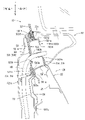
- the door according to this embodiment is the front door on the right side of the vehicle.
- the front-rear, left-right, and up-down in the figure correspond to the front-back, left-right, and up-down of the vehicle provided with the front door.
- the front door 10 is composed of a door main body portion 20 for accommodating a door glass 31 that can be raised and lowered, and a window frame portion 30 provided on the upper side of the door main body portion 20.
- the door body 20 is such that the outer panel 22 constituting the design surface of the front door 10 and the inner panel 23 on the passenger compartment side are aligned from the front and back. By being joined at the peripheral portions of each other, it is configured in the shape of a shallow square box with an internal space.
- An upper end opening (not shown) for inserting and removing the door glass 31 is formed on the upper end surface of the door body 20, and a mechanism for moving the door glass 31 up and down and a door reinforcement are formed in the internal space of the door body 20. Members etc. are stored.
- a pair of upper and lower hinge mechanisms are provided at the front end position of the door body 20, and the door body 20 is connected to the front end of the door opening of the vehicle body (not shown) via these hinge mechanisms. It is attached to the edge.
- the front door 10 can be horizontally rotated between the fully closed position where the door opening is closed and the fully open position where the entrance is fully opened.
- a door lock mechanism (not shown) is provided at the rear end position of the door body 20 in which the front door 10 engages with the striker of the vehicle body in a state where the door opening is closed.
- the window frame portion 30 of the front door 10 constitutes an edge portion of the window frame portion 30, and has a door frame 33 that receives an edge of the door glass 31 that has risen to an upper limit position and a door glass. It includes a front guide rail 35 that guides the elevating and lowering of the door glass 31 on the front side, and a strut-shaped frame 37 that also guides the elevating and lowering of the door glass 31 on the rear side.
- the door frame 33 rises at the front end position of the door main body 20, and extends diagonally rearward and upward, a rising portion 33k, a bent portion 33w connected to the rear end of the rising portion 33k, and a bent portion 33w. It is composed of a straight portion 33u extending rearward from the end and connecting to the upper end of the support column-shaped frame 37.
- the door frame 33 is formed into a substantially T-shaped cross section by continuously bending a steel plate by, for example, roll forming molding, and has a rising portion.
- the cross-sectional shapes of 33k, the bent portion 33w, and the straight portion 33u are configured to be the same.
- an outer peripheral groove portion 335 is formed along the door frame 33, and the outer peripheral groove portion 335 is a weather that seals between the front door 10 and the peripheral edge of the door opening (not shown) of the vehicle body.
- the strip 45 is fitted.
- an inner peripheral groove portion 336 is formed on the inner peripheral side of the door frame 33, and a glass run (not shown) received by sandwiching the end edge of the door glass 31 is fitted in the inner peripheral groove portion 336.
- the front guide rail 35 is a rail that guides the raising and lowering of the door glass 31 on the front side, and is formed into a substantially U-shaped cross section as shown in FIG.
- the front guide rail 35 is erected in a slightly backward tilted state, and the lower end portion thereof is fixed to the inside of the door main body portion 20.
- the upper portion of the front guide rail 35 projects upward from the door main body portion 20, and the upper end portion of the front guide rail 35 is connected to the lower side surface of the rising portion 33k of the door frame 33.
- the front guide rail 35 is a rail having a substantially U-shaped cross section having a groove portion 35 m to be opened on the rear side, and the groove portion 35 m is connected to the inner peripheral groove portion 336 of the door frame 33.
- An extension portion of the glass run 43 fitted in the inner peripheral groove portion 336 of the door frame 33 is fitted in the groove portion 35 m of the front guide rail 35.
- the strut-shaped frame 37 provided on the rear side of the window frame portion 30 is also provided with a groove portion (not shown) that opens on the front side, and the groove portion is connected to the inner peripheral groove portion 336 of the door frame 33. ..
- the glass run 43 is fitted in the groove of the support column 37.
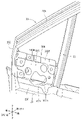
- a mirror bracket to which the door mirror 60 is attached is attached to the lower half of the range surrounded by the rising portion 33k of the door frame 33 and the front guide rail 35 on the upper side of the door body portion 20. 50 is provided. Further, on the upper side of the mirror bracket 50, a fixed glass 32 that closes the range surrounded by the rising portion 33k of the door frame 33 and the front guide rail 35 is provided.
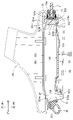
- the mirror bracket 50 is a bracket to which the door mirror 60 is mounted, and is composed of a door mirror mounting panel 500 and a protector 520 as shown in FIGS. 2 to 4.
- the door mirror mounting panel 500 is formed in a substantially box shape from the plate outer 501 on the outside of the door and the plate inner 503 on the inside of the door.
- the plate outer 501 is provided with a vertical flange portion 501f at the upper end portion, and a shelf-shaped step portion below the vertical flange portion 501f. 501d is provided. Then, as shown in FIG. 3, a seal member 32s that supports the fixed glass 32 is fixed on the stepped portion 501d of the plate outer 501.
- a vertical wall portion 501w is provided below the step portion 501d of the plate outer 501.
- the vertical wall portion 501w is formed with a bolt hole (not shown) for attaching the door mirror 60 and an opening 501h through which the wire harness 65 (see FIG. 3) of the door mirror 60 is passed.
- the vertical flange portion 22f of the outer panel 22 of the door body portion 20 and the vertical flange portion 25f of the outer reinforce 25 Is joined by welding or the like.
- the lower side of the vertical wall portion 501w of the plate outer 501 is bent inward (left side) in the vehicle width direction to form a horizontal wall portion 501y, and the left end of the horizontal wall portion 501y is downward.
- the left vertical wall portion 501x is formed by being bent into.
- the inner panel 23 of the door body 20 and the lower portion of the inner reinforcement 26 are joined to the lower portion 501z of the left vertical wall portion 501x of the plate outer 501 by welding or the like.
- the plate inner 503 of the door mirror mounting panel 500 is provided with a vertical flange portion 503f at the upper end portion, and a vertical wall portion 503w is provided below the vertical flange portion 503f.
- the vertical flange portion 503f of the plate inner 503 is joined to the vertical flange portion 501f of the plate outer 501 by welding or the like.
- the vertical wall portion 503w of the plate inner 503 has an opening 503h through which the wire harness 65 (see FIG. 3) of the door mirror 60 is passed, and a work hole for bolt tightening (not shown). It is provided. Further, as shown in FIG.
- a lower flange portion 503x is formed on the lower side of the vertical wall portion 503w of the plate inner 503.
- the upper side surface of the left vertical wall portion 501x of the plate outer 501 is joined to the lower flange portion 503x of the plate inner 503 by welding or the like.
- the vertical flange portion 23f of the inner panel 23 of the door body portion 20 and the vertical flange portion 26f of the inner reinforcement 26 are joined to the lower flange portion 503x of the plate inner 503 by welding or the like.
- a vertically long opening Sf is formed between the front end edge of the door mirror mounting panel 500, that is, the front end edge 501 m of the plate outer 501 and the front end edge 503 m of the plate inner 503. Then, the door frame 33 is fitted to the vertically long opening Sf of the front end edge of the door mirror mounting panel 500. Further, a vertically long opening Sb extending linearly in the vertical direction is formed between the rear end edge of the door mirror mounting panel 500, that is, the rear end edge 501b of the plate outer 501 and the rear end edge 503b of the plate inner 503. Has been done.
- the vertically long opening Sb at the rear end edge of the door mirror mounting panel 500 is closed by the vertically long block portion 524 of the protector 520 (described later), and the front guide rail 35 is set with respect to the vertically long block portion 524.
- the protector 520 covers the plate inner 503 of the door mirror mounting panel 500 from the indoor side, and the door front side and the door formed between the door mirror mounting panel 500 and the front guide rail 35. It is a member that closes the gap with the inside.
- the protector 520 is an injection molded product of resin, and as shown in FIGS. 4 and 7, a covering portion 521 that covers the plate inner 503 of the door mirror mounting panel 500 from the indoor side and a rear end of the door mirror mounting panel 500. It is provided with a vertically long block portion 524 that closes the vertically long opening Sb at the edge. Then, the covering portion 521 and the vertically elongated block portion 524 of the protector 520 are connected by an integral hinge 523 as shown in FIGS. 7 and 8.
- the covering portion 521 of the protector 520 is provided with a vertical wall portion 521m that covers from the vertical flange portion 503f at the upper end portion of the plate inner 503 to the lower end portion of the vertical wall portion 503w.
- a cable opening 521h through which the wire harness 65 of the door mirror 60 is passed is formed in the vertical wall portion 521m of the covering portion 521 at a position corresponding to the opening 503h of the plate inner 503.
- the inner panel 23 of the door main body portion 20 is in a state of slightly protruding toward the room side from the vertical wall portion 521 m.
- a stepped vertical wall portion 521x that covers the vertical flange portion 23f of the inner reinforce 26 and the vertical flange 26f of the inner reinforce 26 is provided.
- a support portion 521y for supporting the wire harness 65 of the door mirror 60 is provided below the stepped vertical wall portion 521x of the covering portion 521.
- a seal portion 521s that closes the gap between the front end edge 503 m of the plate inner 503 of the door mirror mounting panel 500 and the door frame 33 is formed on the front end edge of the covering portion 521 of the protector 520.
- a vertically long block portion 524 is connected to the rear end edge of the covering portion 521 of the protector 520 via an integral hinge 523. That is, a vertically long block portion 524 is connected to the rear end edge of the covering portion 521 of the protector 520 in a state of being horizontally rotatable about the integral hinge 523.
- the vertically long block portion 524 of the protector 520 is a vertically long columnar block, and as shown in FIGS. 4 and 8, a vertically long lid that closes the vertically long opening Sb of the rear end edge of the door mirror mounting panel 500 on the back surface side.
- the shaped portion 524k is formed.
- a vertical groove 524v into which the rear end edge 503b of the plate inner 503 fits on both sides of the vertically long lid-shaped portion 524k and a step portion where the rear end edge 501b of the plate outer 501 fits. 524d and the like are formed.
- a rail positioning portion 524s for fitting the front guide rail 35 in a state of being restrained from both sides in the width direction is provided.
- the protector 520 is in a state in which the covering portion 521 and the vertically elongated block portion 524 are expanded, that is, a state in which the front and back surfaces of the covering portion 521 and the front and back surfaces of the vertically long block portion 524 are arranged in the same direction. It is molded by a molding die. This makes it possible to easily configure the molding die.
- the vertical flange portion 501f at the upper end of the plate outer 501 and the vertical flange portion 503f at the upper end of the plate inner 503 in the door mirror mounting panel 500 are joined to each other by welding or the like. Further, the lower flange portion 503x of the plate inner 503 and the upper side surface of the left vertical wall portion 501x of the plate outer 501 are also joined by welding or the like. As a result, the door mirror mounting panel 500 is formed in a substantially box shape by the plate outer 501 and the plate inner 503. Next, as shown in FIG.
- the door mirror mounting panel 500 has a lower portion than the lower portion of the vertical wall portion 501w such as the plate outer 501 from the upper end opening (drawing number omitted) of the door main body portion 20 to the door main body. It is stored in the front end of the internal space of the portion 20. Further, as shown in FIGS. 4, 5 and the like, the door mirror mounting panel 500 is positioned at a position where the vertically long opening Sf at the front end portion fits with the door frame 33.
- the lower flange portion 503x and the like of the plate inner 503 of the door mirror mounting panel 500 are the vertical flange portion 23f of the inner panel 23 of the door body portion 20 and the vertical flange portion 26f of the inner reinforce 26. Is joined by welding or the like. Further, the lower portion 501z of the left vertical wall portion 501x of the plate outer 501 is joined to the inner panel 23 of the door main body portion 20 and the lower portion of the inner reinforce 26 by welding or the like. Further, as shown in FIGS.
- the lower outer surface of the vertical wall portion 501w of the plate outer 501 is formed on the vertical flange portion 22f of the outer panel 22 of the door body portion 20 and the vertical flange portion 25f of the outer reinforcement 25. It is joined by welding or the like. In this state, the installation of the door mirror mounting panel 500 is completed.
- the covering portion 521 of the protector 520 includes a vertical flange portion 503f, a vertical wall portion 503w, and an inner of the door body portion 20 of the plate inner portion 503 of the door mirror mounting panel 500. It is mounted in place so as to cover the top of the panel 23. As a result, the gap between the plate inner 503 of the door mirror mounting panel 500 and the door frame 33 is closed by the seal portion 521s of the covering portion 521.
- the vertically elongated block portion 524 of the protector 520 is rotated counterclockwise by about 90 ° about the integral hinge 523, so that the vertically elongated lid-shaped portion of the vertically elongated block portion 524 is as shown in FIG. 524k is fitted into the vertically elongated opening Sb at the rear end edge of the door mirror mounting panel 500.
- the vertically long lid-shaped portion 524k of the vertically long block portion 524 is fitted into the vertically long opening Sb between the rear end edge 503b of the plate inner 503 of the door mirror mounting panel 500 and the rear end edge 501b of the plate outer 501.
- the opening Sb is closed.
- the front guide rail 35 is fitted and positioned in the rail positioning portion 524s of the vertically elongated block portion 524 of the protector 520.
- the lower portion of the front guide rail 35 is connected to the inside of the door main body 20, and the upper end of the front guide rail 35 is connected to the lower side surface of the rising portion 33k of the door frame 33. Installation of 35 is completed.
- the door mirror 60 has a plate outer as shown in FIG. 4 and the like in a state where the wire harness 65 of the door mirror 60 is passed through the openings 501h and 503h of the door mirror mounting panel 500 and the cable opening 521h of the protector 520. Bolted to 501. Then, as shown in FIG. 3, the wire harness 65 of the door mirror 60 is supported by the support portion 521y of the covering portion 521 of the protector 520 by, for example, binding. This makes it possible to prevent damage and noise caused by the wire harness 65 rubbing against the door mirror mounting panel 500 and the inner panel 23 of the door body 20.
- the door mirror mounting panel 500, the protector 520, the wire harness 65, and the inner panel 23 of the door body 20 are covered with the door trim 68, which is an interior material, as shown in FIG.
- the front door 10 in the present embodiment corresponds to the door of the vehicle of the present invention
- the door frame 33 of the window frame portion 30 corresponds to the window frame frame in the present invention
- the protector 520 corresponds to the closing member of the present invention
- the front guide rail 35 corresponds to the guide rail of the present invention.
- the gap between the front side of the door and the inside of the door formed between the door mirror mounting panel 500 and the front guide rail 35 (guide rail) is closed by the protector 520 (closing member). ing. Therefore, the air flowing along the door mirror 60 swirls outside the door glass 31 behind the door mirror when the vehicle is running, and the air swirls from the gap between the door mirror mounting panel 500 and the front guide rail 35 to the door mirror mounting panel 500. It doesn't get inside. As a result, the wind noise of the door mirror 60 portion when the vehicle is running can be suppressed.
- a rail positioning portion 524s for positioning the front guide rail 35 by sandwiching it from both sides in the width direction is provided on the front side of the vertically long block portion 524 of the protector 520 (closing member). Therefore, the efficiency of the work of attaching the upper end of the front guide rail 35 to the door frame 33 (window frame frame) and the work of attaching the front guide rail 35 to the door main body 20 is improved. Further, since the covering portion 521 of the protector 520 and the vertically long block portion 524 are connected by the integral hinge 523, the protector 520 can be molded in a flatly expanded state. For example, the protector 520 is molded. The structure of the molding mold is simplified.
- the covering portion 521 of the protector 520 is provided with a supporting portion 521y that supports the wire harness 65 of the door mirror 60. Therefore, by binding the wire harness 65 to the support portion 521y of the protector 520, it is possible to prevent damage and noise caused by the wire harness 65 rubbing against the plate inner 503 or the like of the door main body portion 20.
- the present invention is not limited to the above embodiment, and changes can be made without departing from the gist of the present invention.
- an example is shown in which the covering portion 521 of the protector 520 and the vertically elongated block portion 524 are connected by an integral hinge 523.
- the front door 10 provided with the fixing glass 32 on the upper side of the door mirror mounting panel 500 of the mirror bracket 50 has been exemplified.
- the present invention to a front door in which the door mirror mounting panel 500 of the mirror bracket 50 covers the entire range surrounded by the door frame 33 and the front guide rail 35. Further, it is also possible to apply the present invention to doors other than the front door 10.
Landscapes
- Engineering & Computer Science (AREA)
- Mechanical Engineering (AREA)
- Window Of Vehicle (AREA)
- Rear-View Mirror Devices That Are Mounted On The Exterior Of The Vehicle (AREA)
Priority Applications (2)
| Application Number | Priority Date | Filing Date | Title |
|---|---|---|---|
| JP2022556709A JP7371793B2 (ja) | 2020-10-13 | 2020-10-13 | 車両のドア |
| PCT/JP2020/038564 WO2022079785A1 (ja) | 2020-10-13 | 2020-10-13 | 車両のドア |
Applications Claiming Priority (1)
| Application Number | Priority Date | Filing Date | Title |
|---|---|---|---|
| PCT/JP2020/038564 WO2022079785A1 (ja) | 2020-10-13 | 2020-10-13 | 車両のドア |
Publications (1)
| Publication Number | Publication Date |
|---|---|
| WO2022079785A1 true WO2022079785A1 (ja) | 2022-04-21 |
Family
ID=81207773
Family Applications (1)
| Application Number | Title | Priority Date | Filing Date |
|---|---|---|---|
| PCT/JP2020/038564 Ceased WO2022079785A1 (ja) | 2020-10-13 | 2020-10-13 | 車両のドア |
Country Status (2)
| Country | Link |
|---|---|
| JP (1) | JP7371793B2 (https=) |
| WO (1) | WO2022079785A1 (https=) |
Cited By (1)
| Publication number | Priority date | Publication date | Assignee | Title |
|---|---|---|---|---|
| SE2350651A1 (en) * | 2023-05-26 | 2024-11-27 | Scania Cv Ab | Vehicle door and vehicle comprising a vehicle door |
Citations (1)
| Publication number | Priority date | Publication date | Assignee | Title |
|---|---|---|---|---|
| JP2018002110A (ja) * | 2016-07-08 | 2018-01-11 | スズキ株式会社 | 車両のドア構造 |
-
2020
- 2020-10-13 JP JP2022556709A patent/JP7371793B2/ja active Active
- 2020-10-13 WO PCT/JP2020/038564 patent/WO2022079785A1/ja not_active Ceased
Patent Citations (1)
| Publication number | Priority date | Publication date | Assignee | Title |
|---|---|---|---|---|
| JP2018002110A (ja) * | 2016-07-08 | 2018-01-11 | スズキ株式会社 | 車両のドア構造 |
Cited By (3)
| Publication number | Priority date | Publication date | Assignee | Title |
|---|---|---|---|---|
| SE2350651A1 (en) * | 2023-05-26 | 2024-11-27 | Scania Cv Ab | Vehicle door and vehicle comprising a vehicle door |
| WO2024248693A1 (en) * | 2023-05-26 | 2024-12-05 | Scania Cv Ab | Vehicle door and vehicle comprising a vehicle door |
| SE547174C2 (en) * | 2023-05-26 | 2025-05-06 | Scania Cv Ab | Vehicle door and vehicle comprising a vehicle door |
Also Published As
| Publication number | Publication date |
|---|---|
| JPWO2022079785A1 (https=) | 2022-04-21 |
| JP7371793B2 (ja) | 2023-10-31 |
Similar Documents
| Publication | Publication Date | Title |
|---|---|---|
| JP6387982B2 (ja) | 自動車のドア構造およびその組立て方法 | |
| US7905531B2 (en) | Apparatus for mounting roof rack to sunroof for vehicles | |
| US20100064591A1 (en) | Vehicle door structure | |
| JP6833480B2 (ja) | 自動車ドア用グラスランの取付構造 | |
| US11479100B2 (en) | Open roof construction for a vehicle | |
| US5819473A (en) | Vehicle door | |
| WO2022079785A1 (ja) | 車両のドア | |
| US10876338B2 (en) | Door glass assembly for vehicle | |
| KR970002075B1 (ko) | 기능도어 카트리지와 그 제조방법 | |
| JP2001171352A (ja) | 自動車用ドア | |
| JP2003104052A (ja) | 車両のドア構造 | |
| JP4887991B2 (ja) | 車両の樹脂ルーフ構造 | |
| EP0243325A2 (en) | Method for assembling a vehicle body with a vehicle door | |
| JP7546450B2 (ja) | 自動車用ドアのシール構造 | |
| CN1796721B (zh) | 车门结构 | |
| JPH0712786B2 (ja) | 自動車のドア構造 | |
| WO2023053253A1 (ja) | 車両のドア | |
| JP4120405B2 (ja) | 車両用ドア | |
| JP2008068765A (ja) | 車両の樹脂ルーフ構造 | |
| JP2009083669A (ja) | スイングスライドドアのカバー構造 | |
| JP4029018B2 (ja) | 車両用ドアインナーモジュール構造 | |
| JP2009262617A (ja) | 車両用ドア構造 | |
| JP2529135Y2 (ja) | 昇降可能なサイドウインドウを有する自動車の車体構造 | |
| US20240174059A1 (en) | Vehicle side portion structure | |
| JP3558871B2 (ja) | サンルーフ装置の開口部構造 |
Legal Events
| Date | Code | Title | Description |
|---|---|---|---|
| 121 | Ep: the epo has been informed by wipo that ep was designated in this application |
Ref document number: 20957614 Country of ref document: EP Kind code of ref document: A1 |
|
| ENP | Entry into the national phase |
Ref document number: 2022556709 Country of ref document: JP Kind code of ref document: A |
|
| WWE | Wipo information: entry into national phase |
Ref document number: 202317020082 Country of ref document: IN |
|
| NENP | Non-entry into the national phase |
Ref country code: DE |
|
| 122 | Ep: pct application non-entry in european phase |
Ref document number: 20957614 Country of ref document: EP Kind code of ref document: A1 |