WO2022075355A1 - 非アクティブ状態のセカンダリセルにおける上りリンクのタイミング制御を行う端末装置、基地局装置、制御方法、およびプログラム - Google Patents
非アクティブ状態のセカンダリセルにおける上りリンクのタイミング制御を行う端末装置、基地局装置、制御方法、およびプログラム Download PDFInfo
- Publication number
- WO2022075355A1 WO2022075355A1 PCT/JP2021/036958 JP2021036958W WO2022075355A1 WO 2022075355 A1 WO2022075355 A1 WO 2022075355A1 JP 2021036958 W JP2021036958 W JP 2021036958W WO 2022075355 A1 WO2022075355 A1 WO 2022075355A1
- Authority
- WO
- WIPO (PCT)
- Prior art keywords
- base station
- terminal device
- station device
- cell
- scell
- Prior art date
- Legal status (The legal status is an assumption and is not a legal conclusion. Google has not performed a legal analysis and makes no representation as to the accuracy of the status listed.)
- Ceased
Links
Images





Classifications
-
- H—ELECTRICITY
- H04—ELECTRIC COMMUNICATION TECHNIQUE
- H04W—WIRELESS COMMUNICATION NETWORKS
- H04W16/00—Network planning, e.g. coverage or traffic planning tools; Network deployment, e.g. resource partitioning or cells structures
- H04W16/24—Cell structures
- H04W16/32—Hierarchical cell structures
-
- H—ELECTRICITY
- H04—ELECTRIC COMMUNICATION TECHNIQUE
- H04W—WIRELESS COMMUNICATION NETWORKS
- H04W56/00—Synchronisation arrangements
-
- H—ELECTRICITY
- H04—ELECTRIC COMMUNICATION TECHNIQUE
- H04W—WIRELESS COMMUNICATION NETWORKS
- H04W72/00—Local resource management
- H04W72/04—Wireless resource allocation
Definitions
- the present invention relates to a transmission timing control technique in a cellular communication system.
- a terminal device connects and communicates with a plurality of cells including a primary cell (PCell) and a secondary cell (SCell) in parallel. ..
- PCell primary cell
- SCell secondary cell
- the present invention provides an efficient communication control technique when a terminal device communicates with a plurality of cells.
- the terminal device is a terminal device capable of connecting and communicating in parallel with the first base station device in the first cell and the second base station device in the second cell. , While the second cell is in a state where user data is not transmitted in the uplink, a predetermined signal that does not include the user data in the uplink is transmitted, and while the second cell is in the state. Based on the adjustment request or instruction notified from the first base station device or the second base station device according to the timing at which the predetermined signal is received in the second base station device. It is configured to continue adjusting the transmission timing so that the signal addressed to the second base station apparatus is received by the second base station apparatus at a predetermined timing.
- the base station device is the base in a system in which a base station device in a first cell and another base station device in a second cell can be connected and communicate in parallel with a terminal device.
- the station apparatus while the second cell is in a state in which user data is not transmitted in the uplink, the other base station apparatus sends a predetermined signal that does not include the uplink user data to the terminal.
- a request for adjusting the transmission timing so that the signal addressed to the other base station device from the terminal device is received by the other base station device at a predetermined timing according to the timing received from the device.
- the instruction is configured to be transmitted to the terminal device.
- the base station device is in a system in which another base station device in the first cell and the base station device in the second cell can be connected and communicate with each other in parallel with the terminal device.
- the base station apparatus while the second cell is in a state in which user data is not transmitted in the uplink, the base station apparatus sends a predetermined signal that does not include the uplink user data to the terminal.
- the above-mentioned request or instruction for adjusting the transmission timing so that the signal addressed to the base station apparatus from the terminal apparatus is received by the base station apparatus at a predetermined timing according to the timing received from the apparatus. It is configured to send to the terminal device.
- the present invention it becomes possible to perform efficient communication control when the terminal device communicates with a plurality of cells.
- FIG. 1 is a diagram showing a configuration example of a wireless communication system.
- FIG. 2 is a diagram showing a hardware configuration example of a terminal device and a base station device.
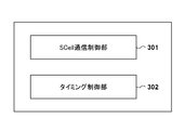
- FIG. 3 is a diagram showing a functional configuration example of the terminal device.
- FIG. 4 is a diagram showing a functional configuration example of the base station device.
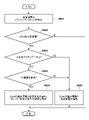
- FIG. 5 is a diagram showing a first example of processing executed by the terminal device.
- FIG. 6 is a diagram showing a first example of processing executed by a network device (base station device).
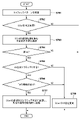
- FIG. 7 is a diagram showing a second example of processing executed by the terminal device.
- FIG. 8 is a diagram showing a second example of processing executed by a network device (base station device).
- FIG. 1 shows a configuration example of a wireless communication system according to the present embodiment.
- the wireless communication system is a cellular communication system, and includes a base station device 101, a base station device 102, and a terminal device 103.
- the base station device 101 and the base station device 102 can be, for example, an eNodeB or gNodeB that can operate in accordance with, for example, Long Term Evolution (LTE) or a fifth generation (5G) cellular communication standard, respectively.
- LTE Long Term Evolution
- 5G fifth generation
- the terminal device 103 can execute communication by establishing a connection with any of the base station devices.
- the terminal device 103 can also establish a connection and communicate with a plurality of base station devices in parallel. At this time, communication between each of the plurality of base station devices and the terminal device 103 is performed using different component carriers, thereby increasing the communication capacity and distributing the amount of traffic communicated in each connection. Can be made to. In this way, carrier aggregation (CA) and dual connectivity (DC) are modes in which the terminal device 103 establishes a connection with a plurality of base station devices in parallel and communicates using the plurality of component carriers. )It has been known.
- CA carrier aggregation
- DC dual connectivity
- the cells corresponding to each component carrier are classified into a primary cell (PCell) and a secondary cell (SCell).
- the cell 111 formed by the base station apparatus 101 may be a PCell
- the cell 112 formed by the base station apparatus 102 may be a SCell.
- the PCell can be an LTE cell and the SCell can be a 5G cell.
- the PCell may be a 5G cell and the SCell may be an LTE cell.
- both PCell and SCell may be LTE cells, or both of these cells may be 5G cells.
- the terminal device 103 can communicate with the SCell while being connected to the PCell.
- the base station device 101 and the base station device 102 can each form a plurality of cells, and the terminal device 103 can be connected in parallel to one or more cells formed by each base station device.
- the SCell is inactive to consume the terminal device 103 (in some cases, the base station device of the SCell). Power can be reduced.
- the SCell is activated.
- the signal transmitted by the terminal device 103 on the uplink can be transmitted in the form of a single carrier-frequency division multiple access (SC-FDMA).
- the base station device receives signals from one or more terminal devices including the terminal device 103.
- a signal in a signal format such as SC-FDMA or OFDMA (Orthogonal Frequency Division Multiple Access)
- the base station device collectively receives an FFT (FFT) for the signals from the plurality of terminal devices.
- FFT Fast Fourier Transform
- TA control a control (TA control) called uplink timing alignment (Timing Alignment) or timing advance (Timing Advance) for adjusting the signal transmission timing of each terminal device is executed.
- the base station device estimates the value of the propagation delay between the terminal device and the base station device based on the received signal from the terminal device, and the terminal sets the estimated value or the value corresponding to the estimated value. Notify the device. Then, the terminal device starts transmitting the signal at a timing earlier than the timing at which the head of the signal should be received in the base station device by the estimated value of the notified propagation delay.
- the base station device can receive signals from a plurality of terminal devices at substantially the same timing.
- the correction value (that is, the value corresponding to the propagation delay) that defines the signal transmission timing of the terminal device is referred to as the TA value.
- Notification of the TA value is performed for each terminal device.
- the first base station device of the PCell and the second base station device of the SCell are the same base station device or are in the same position, or when these base station devices are sufficiently close to each other. May be placed. In such a case, since the magnitudes of the propagation delays between these base station devices and the terminal devices are almost the same, a common TA value can be used for these base station devices.
- the terminal device uses a different TA value for each base station device.
- the terminal device communicates with the PCell and SCell formed by one base station device, and is further formed by another base station device as needed.
- One or more SCells can also communicate.
- a common TA value can be used for a plurality of cells formed by one base station device, and another TA value can be used for cells formed by another base station device.
- an identifier such as a TAG ID (Timing Advance Group Identity) can be set for each of the TA values commonly used in the plurality of cells. Further, the terminal device may be notified in advance by a cell identifier or the like which cell the TA value is applied to.
- TAG ID Temporal Advance Group Identity
- the terminal device While the SCell is in the inactive state, it can be assumed that the connection between the terminal device and the base station device of the SCell is disconnected, and the TA control is also terminated. In this case, since it is necessary to establish time synchronization in order to reactivate the SCell, the terminal device performs a random access (RACH) procedure with the SCell's base station device to establish a connection. Will be done. However, when performing such a RACH procedure, it takes a long time to establish a connection, and it may take a long time for SCell to be activated and communication to be possible. In particular, when the RACH procedure is executed each time when communication with SCell occurs periodically, signals that do not carry user data are frequently transmitted and received to establish a connection, resulting in deterioration of frequency utilization efficiency and consumption. Problems such as increased power consumption can occur.
- RACH random access
- TA control is maintained even when the SCell is in an inactive state. That is, the terminal device keeps transmitting the uplink signal at a constant frequency while the SCell is inactive. Then, the base station apparatus of SCell measures the propagation delay using the uplink signal, and performs TA control based on the propagation delay. It can be assumed that the SCell base station device cannot transmit the TA control signal during the inactive state in relation to the terminal device. In this case, the SCell base station device notifies the PCell base station device of information for TA control (for example, a propagation delay estimated value), and executes TA control regarding the SCell of the terminal device via the PCell. You may do it.
- information for TA control for example, a propagation delay estimated value
- the terminal device can continue to update the value of TA for the SCell even while the SCell is inactive. Then, according to such a procedure, the terminal device does not need to execute the RACH process because it is not necessary to establish the time synchronization again when the SCell transitions to the active state. Therefore, it is possible to immediately start transmitting uplink user data (although processing such as downlink radio quality (CQI) measurement and reporting may be performed in some cases), and communication via SCell is possible. The time required to achieve this can be significantly reduced.
- CQI downlink radio quality
- the "inactive state" in the present embodiment is defined as a state in which at least a predetermined signal can be transmitted.
- a state in which the terminal device can transmit a predetermined signal without user data is referred to as an "inactive state”.
- the predetermined signal here may be, for example, a sounding reference signal (SRS), a physical uplink control channel (PUCCH), or a demodulation reference signal (DMRS).
- SRS sounding reference signal
- PUCCH physical uplink control channel
- DMRS demodulation reference signal
- the physical downlink shared channel (PDSCH) and the physical uplink shared channel (PUSCH) are not transmitted / received.
- the inactive SCell can take, for example, an inactive state only for the uplink, an inactive state only for the downlink, and an inactive state for both the uplink and the downlink.
- the terminal device When only the uplink is inactive, the terminal device does not transmit user data in the SCell, but only transmits a predetermined signal (SRS, PUCCH, DMRS, etc.) for TA control. On the other hand, the terminal device may receive user data on the downlink. In one example, when only the uplink is inactive, the terminal device does not transmit the SRS in the SCell, but only the PUCCH including the acknowledgment (ACK / NACK) for the downlink user data. sell. The SCell base station device can estimate the propagation delay by receiving this PUCCH. Then, when notification such as the timing at which the TA value should be updated is required, the SCell base station device directly to the terminal device or to the terminal device via the PCell base station device for TA control.
- the terminal device should transmit the SRS. You may do it. Further, even in such a case, the terminal device may transmit the PUCCH including the measurement report of the radio quality or the DMRS instead of the SRS.
- the terminal device determines the uplink when the transmission of the uplink user data (PUSCH) should be stopped (for example, based on an instruction from the PCell base station device or the SCell base station device).
- the transmission of the signal is started and the transmission of the downlink user data (PDSCH) should be stopped in that state (for example, based on the instruction from the PCell base station device or the SCell base station device)
- the predetermined time can be changed from PUCCH to SRS.
- the terminal device may change the predetermined signal type from SRS to PUCCH if the PDSCH transmission is resumed while the PUSCH transmission should be stopped. Further, the terminal device may stop the transmission of a predetermined signal when the transmission of the PUSCH is resumed.
- the terminal device When only the downlink is inactive, the terminal device does not receive the user data on the SCell, but continues to transmit the user data on the uplink. Therefore, TA control is continued.
- Information to be notified from the base station device (network) to the terminal device such as adjustment of the TA value, may be notified from the base station device of the PCell to the terminal device, for example.
- user data is not transmitted or received, but when transmission of control information is permitted, for example, a TA value adjustment request / adjustment instruction is transmitted from the SCell base station device to the terminal device. May be done.
- the terminal device When both the uplink and the downlink are inactive, the terminal device does not both send and receive user data in the SCell. In this case, since the terminal device does not receive the PDSCH, it does not transmit the PUCCH for ACK / NACK. Therefore, the terminal device may be configured to periodically transmit, for example, SRS or DMRS. The terminal device may periodically transmit the PUCCH including the measurement report of the radio quality in the inactive SCell. The SCell base station device can estimate the propagation delay by receiving these uplink signals. Then, the base station apparatus of SCell can transmit a message for TA control when notification such as the timing at which the TA value should be updated is required.
- the terminal device since the downlink is also inactive, the terminal device may not be able to receive the downlink signal of the SCell.
- the SCell base station device can transfer information for TA control to the terminal device via the PCell base station device.
- the terminal device may be capable of receiving predetermined downlink control information in the inactive SCell.
- the SCell base station device can directly notify the terminal device of information for TA control.
- a predetermined uplink for TA maintenance control used in each cell (or a cell group composed of the plurality of cells) is specified.
- the signals may be different signals.
- uplink signal transmission for TA maintenance control may be set only for any one cell.
- the information for TA control can specify the timing at which the terminal device transmits a signal to the base station device of the SCell so that the signal is received at a predetermined reception timing. It can be any information. That is, it may be a request for changing the transmission timing transmitted by the base station device to the terminal device during the conventional TA control, or may be information in another format.
- the information for TA control is transmitted from the PCell base station device or the SCell base station device to the terminal device by downlink control information (DCI) or medium access control / control element (MAC CE). sell.
- DCI downlink control information
- MAC CE medium access control / control element
- the information for TA control may be notified to the terminal device including the identification information (ID) of the cell (or cell group) subject to the control.
- the terminal device identifies the cell identification information from the received information, and determines the transmission timing for the SCell corresponding to the identification information by using the transmission timing adjustment parameter included in the information. Then, the terminal device controls the transmission timing of the uplink signal according to the determination result.
- This transmission timing control is applied when the above-mentioned predetermined signal (SRS / PUCCH / DMRS) is transmitted to the SCell in which the uplink is inactive. That is, the terminal device continuously adjusts the transmission timing under TA control in the SCell in the inactive state, so that the user data is transmitted without adjusting the timing again after the SCell becomes active. Will be able to.
- the terminal device can periodically transmit the predetermined signal of the uplink described above.
- the cycle at this time may be, for example, the same as or different from the transmission cycle of PUCCH, SRS, or DMRS transmitted by the terminal device in the active state.
- a given uplink signal may be transmitted at a longer cycle (ie, less frequently) than the active cycle, or at a shorter cycle (ie, higher frequency) than the active cycle. )
- a predetermined signal of the uplink may be transmitted.
- the timer is reset every time the PUCCH is transmitted.
- SRS or PUCCH may be transmitted.
- the period for transmitting a predetermined uplink signal can be set, for example, from the base station device (network side).
- the PCell base station appliance in some cases, the SCell base station appliance
- sends an RRC (radio resource control) message for example, an LTE RRC Connection Reconfiguration message or a 5G RRC Reconfiguration message.
- RRC message may include information such as the transmission cycle of a predetermined signal of the uplink in the inactive state. Further, for example, this information may be notified to the terminal device by DCI or MAC CE included in the signal transmitted by the base station device of PCell or SCell.
- the opportunity for transmitting a predetermined uplink signal may be specified by, for example, a subframe number or the like.
- the terminal device may be made to transmit a predetermined signal of the uplink for TA control at a designated opportunity from the network side.
- the cell identifier and the TA control commonly performed in a group of one or more cells each consisting of the plurality of cells are used.
- the transmission cycle of a predetermined signal of the uplink may be set.
- the activation / deactivation of the SCell can be controlled according to the amount of traffic transmitted and received between the SCell base station device and the terminal device.
- the base station device of the PCell may determine the traffic pattern of the terminal device and activate / deactivate the SCell according to the traffic pattern.
- the base station device of PCell is a long-term evolution (LTE) base station device
- this base station device receives Subscription Based UE Differentiation Information included in the DOWNLINK NAS TRANSPORT message from the MME (movement management entity). Can be done.
- LTE long-term evolution
- the PCell base station device is a 5G base station device
- NG New Generation
- AMF access and mobility management function
- UPF user plane function
- the interface can acquire information that can identify the traffic pattern such as what kind of device the terminal device is used for. Then, the PCell base station device identifies the traffic pattern of the terminal device from these information, specifies the cycle in which communication is performed and the amount of data to be transmitted / received, and activates / deactivates the SCell based on the specific result. The period of activation can be determined. Further, the base station device of the PCell may specify the traffic pattern according to the communication history, for example, and determine the cycle for activating / deactivating the SCell.
- the base station apparatus of the PCell may determine that the SCell is added and deleted periodically.
- the PCell base station device can determine the activation / deactivation cycle of each SCell when there are a plurality of SCells.
- determining the activation cycle for example, one or more SCells may be treated so as not to be activated even once.
- a determination condition for determining SCell treated as such inactive can be set in advance. This determination condition may include, for example, cell load, frequency, radio quality level, allowable delay amount of transmitted / received data, and the like. As a result, for example, it is possible to prevent the SCell in a high load state from being activated, resulting in a state in which the terminal device cannot sufficiently perform communication with the SCell.
- the PCell is a macrocell, and in this case, since the PCell is used by many UEs, it may be necessary to keep the amount of data transmitted / received in the PCell low.
- the PCell base station apparatus needs to calculate in advance how much data can be transmitted / received in the SCell, and transmit / receive in the PCell based on the calculation result. The amount of data may be calculated. As a result, the amount of data transmitted / received in the SCell can be maximized, and the amount of data transmitted / received in the PCell can be kept low.
- the data to be transmitted / received between the terminal device and the network is generated at 6 Mbytes per second. At this time, it is assumed that these data are transmitted and received by 3 Mbytes between the PCell and the SCell. Further, it is assumed that the communication speed of the PCell is 30 Mbps and the communication speed of the SCell is 60 Mbps. In this case, it takes 800 milliseconds to complete the communication with the PCell and 400 milliseconds to complete the communication with the SCell. Therefore, the time from the completion of communication to the generation of the next data is 600 milliseconds in SCell. Therefore, the SCell may be active for a period of 400 ms and inactive for the remaining 600 ms.
- the PCell base station device identifies the traffic pattern of the terminal device as described above and, as a result, controls the SCell to be inactive for a period of 600 milliseconds per second. sell. For example, the PCell base station device deactivates the SCell to the terminal device and the SCell base station device 400 ms after the start of data transmission, and activates the SCell again 600 ms later. Can be instructed to do. This instruction may be given by, for example, an RRC message (for example, an LTE RRCConnectionReconfiguration message or a 5G RRCReconfiguration message) transmitted from a PCell base station device, or a MAC CE or DCI included in a downlink signal.
- an RRC message for example, an LTE RRCConnectionReconfiguration message or a 5G RRCReconfiguration message
- these information include information indicating whether to instruct activation / deactivation and identification information such as the physical cell identifier of the SCell to be switched between the active state and the inactive state.
- information indicating whether or not to maintain TA control in the inactive state may be included in the information instructing the inactivation of the SCell. For example, if the terminal device does not perform uplink communication on the SCell for a long period of time, maintaining TA control increases power consumption by continuing uplink signal transmission. In this case, information indicating that TA control is not maintained may be included. In this case, the SCell setting may be canceled instead of deactivating the SCell.
- the information indicating the deactivation of the SCell includes predetermined information indicating the maintenance of the TA control. It may be included. That is, when the TA control is not maintained, the information indicating that the TA control is not maintained may not be included in the information indicating that the TA control is not maintained. In this case, the terminal device continues to transmit the uplink signal for maintaining TA control only when it detects predetermined information indicating that TA control should be maintained in the information indicating the deactivation of SCell. On the other hand, if such predetermined information is not detected, the uplink signal for maintaining TA control is not transmitted.
- the PCell base station device may transmit the above instructions to the terminal device via the SCell base station device.
- the instruction via the SCell base station device can be given when the SCell is active at least on the downlink. Even if the SCell is inactive on the downlink, if the terminal device is supposed to receive some control signal from the SCell base station device, the above instruction is given to the SCell base station device. It may be included in the control signal and transmitted.
- the time from the completion of communication to the generation of the next data is 200 milliseconds. Therefore, the PCell base station device can use this 200-millisecond period for signaling for TA control (for example, transmission of a TA value adjustment request / adjustment instruction to a terminal device).
- the SCell base station device may provide a determination as to whether or not to activate / deactivate the SCell and an opportunity to activate / deactivate the SCell. That is, the SCell base station device acquires information that can identify the traffic pattern of the terminal device described as being acquired by the PCell base station device, determines activation / deactivation of the SCell, and determines the activation / deactivation of the SCell. It is possible to perform control such as sending an instruction message or the like to the terminal device according to the above. The content of the process is the same as the above-mentioned process when it is executed by the PCell base station device. Further, the SCell base station device may send and receive control messages to and from the terminal device via the PCell base station device.
- the transmission of the instruction via the PCell can be executed without any special condition.
- the SCell base station device can transmit the above instructions to the terminal device via the PCell base station device.
- the terminal device may give a determination as to whether or not to activate / deactivate the SCell and an opportunity for the activation / deactivation. That is, the terminal device can execute the determination of activation / deactivation of the SCell based on, for example, the pattern of the traffic sent and received by the own device. Then, the terminal device may request the base station device of the PCell or the base station device of the SCell to activate / deactivate the SCell based on the determination.
- the terminal device has, for example, identification information such as the physical cell identifier of the SCell to be activated / deactivated, and information indicating that activation or deactivation is requested (for example, information indicating a state after transition).
- a request message including the above can be transmitted to the base station device of PCell or the base station device of SCell.
- the terminal device may transmit this request to the base station device of the PCell, for example, when the uplink of the SCell is inactive.
- the terminal device may transmit this request to either the base station device of the PCell or the base station device of the SCell when the uplink of the SCell is in the active state.
- This request can be transmitted from the terminal device to the PCell or SCell base station device, for example, by an RRC message such as measurement report or UEAssistance Information.
- this request may be included in the MAC CE or uplink control information (UCI) in the uplink signal transmitted from the terminal device to the base station device of PCell or SCell.
- UCI uplink control information
- the PCell base station device or the SCell base station device can execute SCell activation / deactivation (state change) in response to receiving this request. It should be noted that the state change of SCell does not necessarily have to be executed. For example, if the radio resources of the PCell or other SCell are sufficient and the requested SCell does not need to be activated, or if additional traffic is generated and the SCell should not be deactivated. For example, the request from the terminal device may be rejected.
- the PCell base station device or the SCell base station device may transmit information indicating whether to perform activation / deactivation of the SCell to the terminal device.
- the PCell base station device or the SCell base station device may transmit information indicating whether or not TA control is maintained in the inactive state to the terminal device. This information may be transmitted along with information indicating whether to perform activation / deactivation of the SCell. Note that, only when the TA control is maintained, predetermined information indicating the maintenance of the TA control may be transmitted to the terminal device. That is, when the TA control is not maintained, the information indicating that the TA control is not maintained may not be explicitly transmitted to the terminal device.
- the terminal device when either the PCell base station device or the SCell base station device transmits a signal such as an activation / deactivation notification to the terminal device, the terminal device in those cells Based on the radio quality, it may be determined which cell of the base station apparatus transmits the signal. This determination can be made, for example, by PCell's base station equipment or other (eg, higher) network nodes.
- the wireless quality is, for example, RSRP (Reference Signal Received Power), RSRQ (Reference Signal Received Quality), RSSI (Received Signal Strength Indicator), RCSP (Received Signal Code Power), SINR (Signal to Interference plus Noise Ratio). It may include at least one.
- SCell activation / deactivation may be performed independently for the uplink and the downlink as described above. That is, the SCell in the inactive state may be in one of the following states: only the uplink is inactive, only the downlink is inactive, and both the uplink and the downlink are inactive. Therefore, the activation / deactivation of the SCell as described above can be performed separately for the uplink and the downlink.
- the information indicating activation / deactivation of the SCell transmitted by the base station device or the terminal device may be configured to indicate whether the information is related to the uplink or the downlink.
- the SCell can be flexibly activated / deactivated, and then the terminal device can be activated / deactivated. Is able to continue the TA control of the uplink as needed. As a result, it is possible to appropriately set activation / deactivation of SCell in an environment where user data to be transmitted by SCell is generated periodically. Further, by continuing the TA control of the uplink by the terminal device, it is not necessary to execute the RACH procedure each time when there is such a frequent state change, and it becomes possible to efficiently perform communication.
- the communication device includes, in one example, a processor 201, a ROM 202, a RAM 203, a storage device 204, and a communication circuit 205.
- the processor 201 is a computer including one or more processing circuits such as a general-purpose CPU (central processing unit) and an ASIC (integrated circuit for a specific application), and is stored in a ROM 202 or a storage device 204.
- the ROM 202 is a read-only memory that stores information such as programs and various parameters related to processing executed by the communication device.
- the RAM 203 is a random access memory that functions as a workspace when the processor 201 executes a program and stores temporary information.
- the storage device 204 is configured by, for example, a detachable external storage device or the like.
- the communication circuit 205 is composed of, for example, a circuit for LTE or 5G wireless communication. Although one communication circuit 205 is shown in FIG.
- the communication device (for example, the terminal device 103 is for LTE and 5G, and the base station device 101 and the base station device 102 are for LTE or 5G). And may have multiple communication circuits (for wired communication).
- the communication device may have a separate communication circuit 205 for each of the plurality of usable frequency bands, or may have a common communication circuit 205 for at least a part of those frequency bands. good.
- the terminal device 103 may have not only the communication circuit 205 for cellular communication but also the communication circuit 205 corresponding to other wireless communication standards such as wireless LAN.
- FIG. 3 shows an example of the functional configuration of the terminal device according to the present embodiment.
- the terminal device has, for example, a SCell communication control unit 301 and a timing control unit 302 as its functional configuration.
- FIG. 3 shows only the functions particularly related to the present embodiment, and the illustration of various other functions that the terminal device may have is omitted.
- the terminal device naturally has other functions generally possessed by the terminal device in the cellular communication system.
- the functional blocks in FIG. 3 are schematically shown, and each functional block may be integrated or further subdivided.
- each function of FIG. 3 may be realized, for example, by the processor 201 executing a program stored in the ROM 202 or the storage device 204, for example, a processor existing inside the communication circuit 205 is predetermined. It may be realized by running the software.
- the SCell communication control unit 301 executes the communication control of the SCell. For example, the SCell communication control unit 301 controls TA in the inactive state in response to an instruction from the PCell base station device or the SCell base station device when the SCell transitions to the inactive state on the uplink. Therefore, control is performed so as to continuously transmit a predetermined signal (for example, SRS, PUCCH, DMRS, etc.). Further, the SCell communication control unit 301 controls, for example, to change a predetermined signal type depending on whether or not the downlink is inactive while the SCell is inactive in the uplink. Can be done.
- a predetermined signal for example, SRS, PUCCH, DMRS, etc.
- the SCell communication control unit 301 when the SCell communication control unit 301 receives an instruction of an opportunity to transmit a predetermined signal (for example, a transmission cycle or a subframe number) from a PCell base station device or a SCell base station device, the SCell communication control unit 301 indicates by the instruction. It can be controlled to send a predetermined signal at the opportunity. Further, the SCell communication control unit 301 activates / deactivates one or both of the uplink and the downlink of the SCell in response to an instruction from the PCell base station device or the SCell base station device, for example. Take control.
- a predetermined signal for example, a transmission cycle or a subframe number
- the SCell communication control unit 301 determines to request activation / deactivation of one or both of the uplink and the downlink of the SCell based on, for example, the traffic pattern of its own device, and responds to the decision.
- the request signal is transmitted to the PCell base station device or the SCell base station device.
- the control for the state change can be executed in response to receiving the notification that the request has been approved by the PCell base station device or the SCell base station device.
- the base station device of the PCell or the base station device of the SCell instructs to continue the TA control when the uplink is deactivated, the predetermined signal is transmitted as described above even in the inactive state. May be to continue. Since the details of the control of the SCell communication control unit 301 are as described above, the details will not be repeated here.
- the timing control unit 302 sequentially adjusts the transmission timing by continuously transmitting a predetermined signal by the SCell communication control unit 301 while the SCell is in an inactive state on the uplink. This keeps the timing of the signal transmitted to the SCell in the proper state even though the uplink is inactive, eliminating the need to perform a RACH procedure during subsequent activation. As a result, when the state of SCell is frequently changed between the inactive state and the active state, the state transition can be efficiently enabled.
- FIG. 4 shows a functional configuration example of the base station device (PCell base station device or SCell base station device) according to the present embodiment.
- the base station apparatus has, for example, a PCell function unit 401, a SCell function unit 402, and a timing adjustment unit 403 as its functional configuration.
- FIG. 4 shows only the functions particularly related to the present embodiment, and the illustration of various other functions that the base station apparatus may have is omitted.
- the base station apparatus naturally has other functions generally possessed by the base station apparatus in the cellular communication system.
- the functional blocks in FIG. 4 are schematically shown, and each functional block may be integrated or further subdivided.
- each function of FIG. 4 may be realized, for example, by the processor 201 executing a program stored in the ROM 202 or the storage device 204, and for example, a processor existing inside the communication circuit 205 may be predetermined. It may be realized by running the software.
- the PCell function unit 401 is a function unit that executes the control process of the PCell as a base station device
- the SCell function unit 402 is a function unit that executes the control process of the SCell as a base station device. Since these functions are as described above, the description thereof will not be repeated here.
- the timing adjusting unit 403 measures (calculates) the propagation delay of a predetermined signal from the terminal device when the base station device is a SCell base station device.
- the TA value to be used is specified, and a timing adjustment instruction / request based on the TA value is transmitted directly to the terminal device or to the terminal device via the base station device of PCell.
- the timing adjustment unit 403 can transmit a timing adjustment instruction / request to the terminal device based on the TA value determined by the SCell base station device.
- FIGS. 5 and 6 show an example of the processing flow when the base station device decides to activate / deactivate the SCell based on the traffic pattern
- FIGS. 7 and 8 show an example of the processing flow when the terminal device determines the traffic pattern.
- An example of the processing flow when deciding whether to activate / deactivate the SCell based on the SCell is shown.
- FIGS. 5 and 7 show an example of a processing flow executed by the terminal device
- FIGS. 6 and 8 show execution by a base station device (PCell base station device or SCell base station device).
- An example of the flow of processing to be performed is shown.
- the "base station device" in the following description may be either a PCell base station device or a SCell base station device, unless otherwise specified. Further, the following description is merely an example, and the detailed operation and the like as described above will not be repeated here.
- the base station device identifies the traffic pattern of the terminal device (S601).
- the base station device identifies the traffic pattern of the terminal device, for example, by acquiring information from a node in a core network such as MME or AMF / UPF, or from a communication history or the like.
- the base station apparatus determines whether it is necessary to activate / deactivate the SCell according to the traffic pattern (S602).
- the base station apparatus determines that it is not necessary to activate / deactivate the SCell (NO in S602), it waits until such a state change is required.
- the base station apparatus determines that it is necessary to activate / deactivate the SCell (YES in S602), the state change deactivates the uplink (UL) in the active state. It is determined whether or not it is included (S603). Then, when the uplink is deactivated (YES in S603), the base station apparatus determines whether to continue TA control with the terminal apparatus (S604). Then, when the base station device determines that TA control is to be continued with the terminal device (YES in S604), the terminal device determines the identification information of the SCell whose state is to be changed and the transition of the SCell to the inactive state.
- the base station appliance has the SCell identification information and the SCell state change. Notify only to the terminal device (S606).
- the base station device sends a notification such as an instruction via another base station device (for example, the SCell base station device for the PCell base station device and the PCell base station device for the SCell base station device). You may go there.
- the terminal device When the terminal device receives the state change instruction including the identification information of the SCell from the base station device (S501), it determines whether the state change instruction indicates that the uplink in the active state is deactivated. (S502). When the state change involves deactivating the uplink in the active state (YES in S502), the terminal device determines whether an instruction to continue TA control has been received (S503). Then, when the terminal device receives the TA control continuation instruction (YES in S503), the terminal device executes the control to deactivate the SCell and outputs a predetermined signal (SRS, PUCCH, DMRS, etc.) in the inactive state. The TA control is continued by setting to continuously transmit (S504).
- SRS predetermined signal
- the terminal device changes the state when the state change does not include deactivating the uplink in the active state (NO in S502) or when there is no instruction to continue TA control (NO in S503).
- the state of SCell is changed according to the instruction (S505). In this case, the terminal device does not transmit a predetermined signal and does not continue TA control even when the uplink is deactivated.
- the terminal device decides to activate / deactivate the SCell based on the traffic pattern.
- the terminal device identifies the traffic pattern of the own device based on the application or the like used in the own device (S701), and determines whether activation / deactivation of the SCell is necessary (S702). ).
- S701 the traffic pattern of the own device based on the application or the like used in the own device
- S702 determines whether activation / deactivation of the SCell is necessary
- a state change request including the identification information of the SCell to be changed is transmitted to the base station apparatus (S703).
- the terminal device transmits this request to the base station device of the PCell.
- the terminal device may transmit the request to either the base station device of the PCell or the base station device of the SCell.
- the base station apparatus Upon receiving this request (S801), the base station apparatus determines whether or not to allow the state change of the SCell specified by the identification information (S802). Then, when this state change is not permitted (NO in S802), the base station device transmits a notification indicating that the state change is rejected to the terminal device (S807). In this case (NO in S704), the terminal device ends the process without changing the state of SCell as it is. On the other hand, when the base station apparatus permits the state change of the SCell (YES in S802), the base station apparatus determines whether the state change includes deactivating the uplink (UL) in the active state (S803).
- the base station apparatus determines whether the state change includes deactivating the uplink (UL) in the active state (S803).
- the base station apparatus determines whether or not to continue TA control with the terminal apparatus (S804). Then, when the base station device determines that the TA control is to be continued with the terminal device (YES in S804), the base station device notifies the terminal device that the state change is permitted and is inactive for the continuation of the TA control. Information indicating that a predetermined signal should be transmitted even in the state is transmitted to the terminal device (S805). It should be noted that these information may be notified to the terminal device by one message, or a part thereof and another part may be notified to the terminal device by a separate message.
- the base station appliance only gives a notification that the state change is allowed. Notify the device (S806).
- the base station device sends a notification such as an instruction via another base station device (for example, the SCell base station device for the PCell base station device and the PCell base station device for the SCell base station device). You may go there.
- the terminal device When the terminal device receives the permission to change the state (YES in S704), the terminal device subsequently determines whether the state change includes deactivating the uplink (UL) in the active state (S705). Then, when the terminal device deactivates the uplink (UL) in the active state (YES in S705), the terminal device determines whether or not the instruction to continue the TA control has been received (S706). When the terminal device receives the TA control continuation instruction (YES in S706), the terminal device executes the control to deactivate the SCell and continuously transmits a predetermined signal (SRS, PUCCH, DMRS, etc.) in the inactive state. The TA control is continued (S707).
- SRS predetermined signal
- the terminal device is set in S703 when the state change does not include deactivating the uplink in the active state (NO in S705) or when there is no instruction to continue TA control (NO in S706).
- the state of SCell is changed according to the transmitted contents (S707). In this case, the terminal device does not transmit a predetermined signal and does not continue TA control even when the uplink is deactivated.
- the SCell when data transmitted / received by SCell periodically (for example, uplink) is generated periodically and SCell needs to be activated periodically, the SCell is activated.
- the RACH procedure at the time can be omitted. Therefore, activation can be completed at high speed, and the time until the start of transmission of user data can be shortened.
- the activation process is simplified, so flexible SCell operation such as operation in which SCell activation and deactivation are repeated frequently can be performed. It will be possible.
Landscapes
- Engineering & Computer Science (AREA)
- Computer Networks & Wireless Communication (AREA)
- Signal Processing (AREA)
- Mobile Radio Communication Systems (AREA)
Abstract
第1のセルの第1の基地局装置および第2のセルの第2の基地局装置と並行して接続して通信することができる端末装置は、第2のセルが上りリンクにおいてユーザデータの送信が行われない状態である間に、上りリンクのユーザデータを含まない所定の信号を送信し、第2のセルが上りリンクにおいてユーザデータの送信が行われない状態である間に、第2の基地局装置において所定の信号が受信されたタイミングに応じて第1の基地局装置または第2の基地局装置から通知される調整の要求または指示に基づいて、第2の基地局装置へ宛てた信号がその第2の基地局装置に所定のタイミングで受信されるようにするための送信タイミングの調整を継続する。
Description
本発明は、セルラ通信システムにおける送信タイミング制御技術に関する。
セルラ無線通信システムでは、キャリアアグリゲーションやデュアルコネクティビティなどの、端末装置がプライマリセル(PCell)およびセカンダリセル(SCell)とからなる複数のセルに並行して接続し、通信を行う技術が使用されている。
本発明は、端末装置が複数のセルと通信を行う際の効率的な通信制御技術を提供する。
本発明の一態様による端末装置は、第1のセルの第1の基地局装置および第2のセルの第2の基地局装置と並行して接続して通信することができる端末装置であって、前記第2のセルが上りリンクにおいてユーザデータの送信が行われない状態である間に、上りリンクのユーザデータを含まない所定の信号を送信し、前記第2のセルが前記状態である間に、前記第2の基地局装置において前記所定の信号が受信されたタイミングに応じて前記第1の基地局装置または前記第2の基地局装置から通知される調整の要求または指示に基づいて、前記第2の基地局装置へ宛てた信号が当該第2の基地局装置に所定のタイミングで受信されるようにするための送信タイミングの調整を継続する、ように構成される。
本発明の一態様による基地局装置は、第1のセルの基地局装置と第2のセルの他の基地局装置とが端末装置と並行して接続して通信することができるシステムにおける前記基地局装置であって、前記第2のセルが上りリンクにおいてユーザデータの送信が行われない状態である間に、前記他の基地局装置が上りリンクのユーザデータを含まない所定の信号を前記端末装置から受信したタイミングに応じて、前記端末装置から前記他の基地局装置へ宛てた信号が当該他の基地局装置に所定のタイミングで受信されるようにするための送信タイミングの調整の要求または指示を、前記端末装置へ送信する、ように構成される。
本発明の別の一態様による基地局装置は、第1のセルの他の基地局装置と第2のセルの基地局装置とが端末装置と並行して接続して通信することができるシステムにおける前記基地局装置であって、前記第2のセルが上りリンクにおいてユーザデータの送信が行われない状態である間に、前記基地局装置が上りリンクのユーザデータを含まない所定の信号を前記端末装置から受信したタイミングに応じて、前記端末装置から前記基地局装置へ宛てた信号が当該基地局装置に所定のタイミングで受信されるようにするための送信タイミングの調整の要求または指示を、前記端末装置へ送信する、ように構成される。
本発明によれば、端末装置が複数のセルと通信を行う際の効率的な通信制御を行うことができるようになる。
本発明のその他の特徴及び利点は、添付図面を参照とした以下の説明により明らかになるであろう。なお、添付図面においては、同じ若しくは同様の構成には、同じ参照番号を付す。
添付図面は明細書に含まれ、その一部を構成し、本発明の実施の形態を示し、その記述と共に本発明の原理を説明するために用いられる。
図1は、無線通信システムの構成例を示す図である。
図2は、端末装置および基地局装置のハードウェア構成例を示す図である。
図3は、端末装置の機能構成例を示す図である。
図4は、基地局装置の機能構成例を示す図である。
図5は、端末装置によって実行される処理の第1の例を示す図である。
図6は、ネットワーク装置(基地局装置)によって実行される処理の第1の例を示す図である。
図7は、端末装置によって実行される処理の第2の例を示す図である。
図8は、ネットワーク装置(基地局装置)によって実行される処理の第2の例を示す図である。
以下、添付図面を参照して実施形態を詳しく説明する。なお、以下の実施形態は特許請求の範囲に係る発明を限定するものではなく、また実施形態で説明されている特徴の組み合わせの全てが発明に必須のものとは限らない。実施形態で説明されている複数の特徴のうち二つ以上の特徴は任意に組み合わされてもよい。また、同一若しくは同様の構成には同一の参照番号を付し、重複した説明は省略する。
(システム構成)
図1に、本実施形態に係る無線通信システムの構成例を示す。本無線通信システムは、セルラ通信システムであり、基地局装置101並びに基地局装置102、および端末装置103を含んで構成される。基地局装置101並びに基地局装置102は、それぞれ、例えばロングタームエボリューション(LTE)や第5世代(5G)のセルラ通信規格に準拠して動作可能なeNodeB又はgNodeBでありうる。なお、これらの基地局装置は、バックホール回線を介して接続可能であり、例えば一方の基地局装置から他方の基地局装置へユーザデータや制御データを転送することが可能に構成される。端末装置103は、いずれかの基地局装置との間で接続を確立することにより、通信を実行することができる。また、端末装置103は、複数の基地局装置との間で、並行して接続を確立して通信することもできる。このとき、複数の基地局装置のそれぞれと端末装置103との間の通信は、異なるコンポーネントキャリアを用いて行われ、これにより、通信の大容量化や各接続で通信されるトラフィックの量を分散させることができる。このように、端末装置103が複数の基地局装置との間で並行して接続を確立して、複数のコンポーネントキャリアを用いて通信を行う態様として、キャリアアグリゲーション(CA)と、デュアルコネクティビティ(DC)が知られている。
図1に、本実施形態に係る無線通信システムの構成例を示す。本無線通信システムは、セルラ通信システムであり、基地局装置101並びに基地局装置102、および端末装置103を含んで構成される。基地局装置101並びに基地局装置102は、それぞれ、例えばロングタームエボリューション(LTE)や第5世代(5G)のセルラ通信規格に準拠して動作可能なeNodeB又はgNodeBでありうる。なお、これらの基地局装置は、バックホール回線を介して接続可能であり、例えば一方の基地局装置から他方の基地局装置へユーザデータや制御データを転送することが可能に構成される。端末装置103は、いずれかの基地局装置との間で接続を確立することにより、通信を実行することができる。また、端末装置103は、複数の基地局装置との間で、並行して接続を確立して通信することもできる。このとき、複数の基地局装置のそれぞれと端末装置103との間の通信は、異なるコンポーネントキャリアを用いて行われ、これにより、通信の大容量化や各接続で通信されるトラフィックの量を分散させることができる。このように、端末装置103が複数の基地局装置との間で並行して接続を確立して、複数のコンポーネントキャリアを用いて通信を行う態様として、キャリアアグリゲーション(CA)と、デュアルコネクティビティ(DC)が知られている。
DCやCAでは、各コンポーネントキャリアに対応するセルが、プライマリセル(PCell)とセカンダリセル(SCell)とに分類される。例えば、基地局装置101によって形成されるセル111がPCellであり、基地局装置102によって形成されるセル112がSCellでありうる。一例において、PCellがLTEのセルであり、SCellが5Gのセルでありうる。また、PCellが5Gのセルであり、SCellがLTEのセルであってもよい。また、PCellとSCellの両方がLTEのセルであってもよいし、これらのセルの両方が5Gのセルであってもよい。端末装置103は、PCellと接続している状態で、SCellと接続して通信を行うことができる。なお、基地局装置101および基地局装置102は、それぞれ複数のセルを構成可能であり、端末装置103は、各基地局装置によって形成された1つ以上のセルに並行して接続しうる。このような通信が行われる場合、端末装置103がSCellとの通信を行わない場合には、SCellを非アクティブ状態とすることにより、端末装置103の(場合によってはSCellの基地局装置の)消費電力を削減することができる。なお、端末装置103とSCellとの通信が再度行われる場合には、SCellがアクティブ化される。
ここで、端末装置103が上りリンクで送信する信号は、シングルキャリア-周波数分割多元接続(SC-FDMA)の形式で送信されうる。基地局装置は、この端末装置103を含む、1つ以上の端末装置から信号を受信する。基地局装置は、複数の端末装置からSC-FDMAやOFDMA(直交周波数分割多元接続)のような信号形式の信号が受信される場合、その複数の端末装置からの信号に対して一括でFFT(高速フーリエ変換)処理を実行する。このFFT処理では、各端末装置から送信される信号の受信タイミングが所定範囲を超えてずれると、そのずれによりキャリア間干渉が発生し、各信号の受信品質が大幅に劣化してしまいうる。このため、各端末装置の信号送信タイミングを調整するための、上りリンクのタイミングアライメント(Timing Alignment)又はタイミングアドバンス(Timing Advance)と呼ばれる制御(TA制御)が実行される。TA制御では、端末装置と基地局装置との間の伝搬遅延の値を、基地局装置が端末装置からの受信信号に基づいて推定して、その推定値又はその推定値に対応する値を端末装置に通知する。そして、端末装置は、基地局装置において信号の先頭が受信されるべきタイミングより、通知された伝搬遅延の推定値だけ早いタイミングで信号の送信を開始する。これにより、基地局装置は、複数の端末装置からの信号をほぼ同じタイミングで受信することができるようになる。
なお、以下では、TA制御において、端末装置の信号送信タイミングを規定する補正値(すなわち、伝搬遅延に対応する値)をTA値と呼ぶ。TA値の通知は端末装置ごとに行われる。ここで、PCellの第1の基地局装置と、SCellの第2の基地局装置とが同じ基地局装置である場合や同じ位置にある場合、又は、これらの基地局装置が十分に近い位置に配置されることがありうる。このような場合には、これらの基地局装置と端末装置との間の伝搬遅延の大きさはほぼ等しくなるため、これらの基地局装置に対して共通のTA値を用いることができる。一方で、第1の基地局装置と第2の基地局装置とが十分に離れた位置に配置された場合、端末装置の位置によってはこれらの基地局装置との伝搬遅延がほぼ等しくなりうるが、一般に、これらの基地局装置のそれぞれに関する伝搬遅延の大きさが異なることとなる。このため、端末装置は、基地局装置ごとに、異なるTA値を使用するようにする。なお、1つの基地局装置が複数のセルを構成する場合には、端末装置は1つの基地局装置が形成するPCellおよびSCellで通信し、さらに、必要に応じて他の基地局装置が形成する1つ以上のSCellでも通信しうる。この場合、1つの基地局装置が形成する複数のセルについては共通のTA値を使用し、他の基地局装置が形成するセルについては別のTA値を使用することができる。この場合、複数のセルに共通に使用されるTA値のそれぞれに例えばTAG ID(Timing Advance Group Identity)などの識別子が設定されうる。また、そのTA値が、どのセルに対して適用されるのかが、セル識別子等によりあらかじめ端末装置に通知されうる。
SCellが非アクティブ状態になっている間、端末装置とそのSCellの基地局装置との間では接続が切断された状態となり、TA制御も終了することが想定されうる。この場合、SCellを再度アクティブ化するためには、時間同期を確立する必要があるため、端末装置は、SCellの基地局装置との間でランダムアクセス(RACH)手順を実行して、接続を確立することとなる。しかしながら、このようなRACH手順を実行する場合、接続が確立するのに長い時間を要し、SCellがアクティブ化され、通信が可能となるまでの時間が長期化されてしまいうる。特に、周期的にSCellでの通信が発生する際などに、都度RACH手順が実行される場合、接続確立のためユーザデータを搬送しない信号の送受信が頻発するため、周波数利用効率の劣化や、消費電力の増大などの問題が発生しうる。
本実施形態では、かかる事情に鑑み、SCellが非アクティブ状態であっても、TA制御を維持するようにする。すなわち、端末装置が、SCellが非アクティブ状態の間に、一定頻度で上りリンク信号を送信し続けるようにする。そして、SCellの基地局装置は、その上りリンク信号を用いて伝搬遅延を測定し、その伝搬遅延に基づいて、TA制御を行う。なお、SCellの基地局装置は、端末装置との関係で非アクティブ状態の間は、TA制御の信号を送信することができないことが想定されうる。この場合、SCellの基地局装置は、PCellの基地局装置へTA制御のための情報(例えば伝搬遅延推定値)を通知し、PCellを経由して、端末装置のSCellに関するTA制御を実行するようにしてもよい。端末装置は、このようにして、SCellが非アクティブ状態の間も、そのSCellに関するTAの値を更新し続けることが可能となる。そして、このような手順によれば、端末装置は、SCellがアクティブ状態に遷移する場合に、改めて時間同期を確立する必要がないため、RACH処理を実行する必要がない。このため、(場合によっては下りリンクの無線品質(CQI)の測定および報告などの処理が実行されうるが)、直ちに上りリンクのユーザデータの送信を開始することができ、SCellでの通信が可能となるまでに要する時間を大幅に短縮することができる。
本実施形態では、上述のように、SCellが非アクティブ状態の間に、上りリンクの(一例においてユーザデータを含まない)所定の信号を送信してTA制御を維持するようにする。このため、本実施形態での「非アクティブ状態」は、少なくとも所定の信号が送信可能な状態として定義される。一例として、本実施形態では、端末装置がユーザデータを伴わない所定の信号を送信可能な状態を、「非アクティブ状態」と呼ぶ。ここでの所定の信号は、例えば、サウンディング参照信号(SRS)や物理上りリンク制御チャネル(PUCCH)、復調基準信号(DMRS)でありうる。一例において、非アクティブ状態では、物理下りリンク共有チャネル(PDSCH)や物理上りリンク共有チャネル(PUSCH)は送受信されない。
なお、非アクティブなSCellは、例えば、上りリンクのみ非アクティブ状態、下りリンクのみ非アクティブ状態、および、上りリンクと下りリンクの両方が非アクティブ状態、の各状態を取りうるものとする。
上りリンクのみ非アクティブ状態の場合、端末装置は、SCellでのユーザデータの送信を行わず、TA制御のための所定の信号(SRS、PUCCH、DMRS等)の送信のみを行う。一方、端末装置は、下りリンクにおいてユーザデータを受信しうる。一例において、端末装置は、上りリンクのみ非アクティブ状態の場合には、SCellにおいて、SRSを送信せず、下りリンクのユーザデータに対する確認応答(ACK/NACK)を含んだPUCCHのみを送信するようにしうる。SCellの基地局装置は、このPUCCHを受信することによって、伝搬遅延を推定することができる。そして、SCellの基地局装置は、TA値の更新がされるべきタイミングなどの通知が必要な場合に、端末装置へ直接、又は、PCellの基地局装置を介して端末装置へ、TA制御のためのメッセージを送信しうる。なお、PDSCHに含まれるユーザデータに対するACK/NACKを送信する必要がない場合や、PDSCHの送信が一定期間にわたって行われないなど、PUCCHを一定期間送信しない場合、端末装置は、SRSを送信するようにしてもよい。また、端末装置は、このような場合にも、SRSではなく、無線品質の測定報告などを含んだPUCCHや、DMRSを送信するようにしてもよい。
なお、一例において、端末装置は、上りリンクのユーザデータ(PUSCH)の送信を停止すべき際に(例えばPCellの基地局装置又はSCellの基地局装置からの指示に基づいて)上りリンクの所定の信号の送信を開始し、その状態で下りリンクのユーザデータ(PDSCH)の送信が停止されるべき際に(例えばPCellの基地局装置又はSCellの基地局装置からの指示に基づいて)その所定の信号の種類をPUCCHからSRSへと変更しうる。一方で、端末装置は、PUSCHの送信を停止すべき状態が維持されている間にPDSCHの送信が再開される場合、所定の信号の種類をSRSからPUCCHへと変更しうる。また、端末装置は、PUSCHの送信が再開される場合に、所定の信号の送信を停止しうる。
下りリンクのみ非アクティブ状態の場合、端末装置は、SCellでのユーザデータの受信を行うことがないが、上りリンクでユーザデータの送信を継続する。このため、TA制御は継続される。なお、TA値の調整などの、基地局装置(ネットワーク)から端末装置へ通知されるべき情報は、例えばPCellの基地局装置から端末装置へ通知されうる。なお、下りリンクにおいて、ユーザデータの送受信が行われないが、制御情報の送信が許容されている場合には、例えばTA値の調整要求/調整指示が、SCellの基地局装置から端末装置へ送信されてもよい。
上りリンクと下りリンクの両方が非アクティブ状態の場合、端末装置は、SCellでのユーザデータの送信と受信の両方を行わない。この場合、端末装置は、PDSCHを受信しないため、ACK/NACKのためのPUCCHを送信することもなくなる。このため、端末装置は、例えば、SRSやDMRSを定期的に送信するようにしうる。なお、端末装置は、例えば無線品質の測定報告などを含んだPUCCHの送信を、非アクティブ状態のSCellにおいて定期的に行うようにしてもよい。SCellの基地局装置は、これらの上りリンクの信号を受信することによって、伝搬遅延を推定することができる。そして、SCellの基地局装置は、TA値の更新がされるべきタイミングなどの通知が必要な場合に、TA制御のためのメッセージを送信しうる。なお、この場合、下りリンクも非アクティブ状態であるため、端末装置はSCellの下りリンク信号を受信できないことがありうる。この場合、SCellの基地局装置は、PCellの基地局装置を介して、TA制御のための情報を端末装置へしうる。なお、端末装置は、非アクティブ状態のSCellにおいて、所定の下りリンクの制御情報を受信できるようにしておいてもよい。この場合には、SCellの基地局装置は、直接、TA制御のための情報を端末装置へ通知しうる。また、一例において、1つの基地局装置が複数のセルを構成する場合には、それぞれのセル(又は複数のセルで構成されるセルグループ)において使用するTA維持制御のための上りリンクの所定の信号を、それぞれ異なる信号としてもよい。また、共通のTA値を使用しうる複数のセルにおいて、TA維持制御のための上り信号送信が、いずれか1つのセルに対してのみ設定されてもよい。
なお、TA制御のための情報は、端末装置がSCellの基地局装置において所定の受信タイミングで信号が受信されるようにするための、その基地局装置へ信号を送信する際のタイミングを特定可能な任意の情報でありうる。すなわち、従来のTA制御の際に、基地局装置が端末装置に宛てて送信する送信タイミングの変更要求であってもよいし、他の形式の情報であってもよい。なお、このTA制御のための情報は、PCellの基地局装置又はSCellの基地局装置から、下りリンク制御情報(DCI)や、媒体アクセス制御・コントロールエレメント(MAC CE)によって、端末装置へ送信されうる。なお、TA制御のための情報は、その制御の対象となるセル(又はセルグループ)の識別情報(ID)を含んで、端末装置に通知されうる。端末装置は、受信した情報からセルの識別情報を特定し、その識別情報に対応するSCellについての送信タイミングを、その情報に含まれる送信タイミング調整パラメータを用いて判定する。そして、端末装置は、その判定結果に応じて、上りリンクの信号の送信タイミングを制御する。この送信タイミングの制御は、上りリンクが非アクティブ状態のSCellに対する上述の所定の信号(SRS/PUCCH/DMRS)の送信時に適用される。すなわち、端末装置が、非アクティブ状態のSCellにおいて、TA制御の下で送信タイミングを調整し続けることにより、そのSCellがアクティブとなった後にタイミングを改めて調整することなく、ユーザデータの送信を行うことができるようになる。
なお、非アクティブ状態において、端末装置は、上述の上りリンクの所定の信号を周期的に送信しうる。なお、このときの周期は、例えば、アクティブ状態において端末装置が送信するPUCCHやSRSやDMRSの送信周期と同じであってもよいし、異なってもよい。例えば、アクティブ状態の周期よりも長い周期で(すなわち、低頻度で)上りリンクの所定の信号が送信されるようにしてもよいし、アクティブ状態の周期よりも短い周期で(すなわち、高頻度で)上りリンクの所定の信号が送信されるようにしてもよい。また、例えばPDSCHへのACK/NACKの送信のためのPUCCHを用いて、非アクティブ状態のTA制御が実行される場合に、PUCCHが送信されるたびにリセットされるタイマを用いて、そのタイマが満了したことに応じて、SRSやPUCCHが送信されるようにしてもよい。なお、非アクティブ状態において、上りリンクの所定の信号を送信する周期は、例えば、基地局装置(ネットワーク側)から設定されうる。例えば、SCellを非アクティブ状態にする際には、PCellの基地局装置(場合によってはSCellの基地局装置)がRRC(無線リソース制御)メッセージ(例えばLTEのRRCConnectionReconfigurationメッセージや5GのRRCReconfigurationメッセージ)を送信しうる。このRRCメッセージに、非アクティブ状態における上りリンクの所定の信号の送信周期などの情報が含められてもよい。また、例えばPCell又はSCellの基地局装置が送信する信号に含まれる、DCI又はMAC CEによって、この情報が端末装置に通知されてもよい。なお、周期の情報のみならず、例えばサブフレーム番号等によって、上りリンクの所定の信号が送信される機会が指定されてもよい。いずれの場合も、端末装置は、ネットワーク側から指定された機会において、TA制御のための上りリンクの所定の信号を送信するようにしうる。また、一例において、1つの基地局装置が複数のセルを構成する場合には、セル識別子や、それぞれが複数のセルからなる1つ以上のセルのグループにおいてそれぞれ共通して行われるTA制御にそれぞれ付与されるTAG ID等の識別子とともに、上りリンクの所定の信号の送信周期が設定されてもよい。
なお、SCellのアクティブ化/非アクティブ化については、SCellの基地局装置と端末装置との間で送受信されるトラフィックの量に応じて制御されうる。例えば、PCellの基地局装置が、端末装置のトラフィックパターンを判定し、そのトラフィックパターンに応じて、SCellのアクティブ化/非アクティブ化を実行しうる。例えば、PCellの基地局装置がロングタームエボリューション(LTE)の基地局装置である場合、この基地局装置は、MME(移動管理エンティティ)から、DOWNLINK NAS TRANSPORTメッセージに含まれるSubscription Based UE Differentiation Informationを受信しうる。また、PCellの基地局装置が5Gの基地局装置である場合、アクセスおよびモビリティ管理ファンクション(AMF)やユーザプレーンファンクション(UPF)との間で定義されている、Downlink NAS TransportなどのNG(New Generation)インタフェースにより、端末装置がどのような用途の装置であるか等のトラフィックパターンを特定可能な情報を取得しうる。そして、PCellの基地局装置は、これらの情報から、端末装置のトラフィックパターンを特定し、通信が行われる周期や送受信されるデータ量を特定し、特定結果に基づいて、SCellをアクティブ化/非アクティブ化する周期を決定しうる。また、PCellの基地局装置は、例えば、通信の履歴に応じて、トラフィックパターンを特定して、SCellをアクティブ化/非アクティブ化する周期を決定してもよい。また、トラフィックパターンによっては、SCellを周期的にアクティブ化/非アクティブ化するのではなく、SCellを周期的に追加/削除する方が、電力消費を低減させることができることが想定される。このような場合には、PCellの基地局装置は、周期的にSCellの追加と削除を行うと判定してもよい。
一例において、PCellの基地局装置は、SCellが複数存在する場合に、それぞれのSCellのアクティブ化/非アクティブ化周期を決定しうる。なお、このアクティブ化周期の決定の際に、例えば1つ以上のSCellについて、一度もアクティブ化しないように取り扱われてもよい。PCellの基地局装置では、このようなアクティブ化されないものとして取り扱われるSCellを判定するための判定条件を、予め設定することができる。この判定条件は、例えば、セルの負荷、周波数、無線品質レベル、送受信されるデータの許容遅延量等が含まれうる。これにより、例えば高負荷状態のSCellがアクティブ化され、その結果、端末装置がそのSCellでの通信を十分に行うことができないなどの状態となることを防ぐことができる。また、PCellはマクロセルであることが想定され、この場合にはPCellが多くのUEによって使用されるため、PCellにおいて送信/受信されるデータ量を低く抑えることが必要となりうる。このために、PCellの基地局装置は、SCellにおいてどれだけのデータを送信/受信することができるかを先に計算し、その計算結果に基づいて、PCellにおいて送信/受信することが必要となるデータ量を算出するようにしてもよい。これにより、SCellにおいて送信/受信されるデータ量を最大化し、PCellにおいて送信/受信されるデータ量を低く抑えることができる。
例えば、端末装置とネットワークとの間で送受信されるべきデータが、毎秒6Mbyte発生するものとする。このとき、これらのデータが、PCellとSCellとで3Mbyteずつ送受信されるものとする。また、PCellの通信速度が30Mbpsであり、SCellの通信速度が60Mbpsであるものとする。この場合、PCellで通信が完了するのに800ミリ秒、SCellで通信が完了するのに400ミリ秒を要する。このため、通信の完了から次のデータが発生するまでの時間が、SCellでは600ミリ秒となる。このため、SCellは、400ミリ秒の期間をアクティブ状態とし、残りの600ミリ秒の期間を非アクティブ状態としうる。一例では、PCellの基地局装置は、上述のようにして端末装置のトラフィックパターンを特定し、その結果として、SCellを1秒のうち600ミリ秒の期間にわたって非アクティブ状態とするように制御を行いうる。例えば、PCellの基地局装置は、端末装置とSCellの基地局装置に対して、データの送信開始から400ミリ秒後にSCellを非アクティブ化することと、その600ミリ秒後に、再度SCellをアクティブ化することを指示しうる。この指示は、例えば、PCellの基地局装置から送信される、RRCメッセージ(例えば、LTEのRRCConnectionReconfigurationメッセージや5GのRRCReconfigurationメッセージ)、又は、下りリンク信号に含まれるMAC CEやDCIにより行われうる。
なお、これらの情報には、アクティブ化/非アクティブ化のいずれを指示するかを示す情報と、アクティブ状態と非アクティブ状態との切り替えの対象となるSCellの物理セル識別子などの識別情報を含む。また、非アクティブ状態においてTA制御を維持するか否かを示す情報が、SCellの非アクティブ化を指示する情報に含まれうる。例えば、端末装置がSCellでの上りリンクの通信を行わない期間が長期化する場合には、TA制御を維持することにより上りリンクの信号送信を継続することによる電力消費が増大してしまうため、この場合には、TA制御を維持しないことを示す情報が含まれうる。この場合、SCellの非アクティブ化ではなく、SCellの設定を解除してもよい。なお、TA制御を維持する場合にのみ、SCellの非アクティブ化を指示する情報(例えば、SCellの識別情報と遷移後の状態を特定可能な情報)に、TA制御の維持を示す所定の情報が含められるようにしてもよい。すなわち、TA制御を維持しない場合には、SCellの非アクティブ化を指示する情報に、TA制御を維持しないことを示す情報が含められなくてもよい。この場合、端末装置は、SCellの非アクティブ化を指示する情報においてTA制御を維持するべきことを示す所定の情報を検出した場合にのみ、TA制御を維持するための上りリンク信号の送信を継続し、一方で、そのような所定の情報を検出しなかった場合には、TA制御の維持のための上りリンク信号の送信を行わないようにする。
なお、PCellの基地局装置は、SCellの基地局装置を介して、端末装置へ上述の指示を送信してもよい。ただし、SCellの基地局装置を経由した指示は、SCellが少なくとも下りリンクにおいてアクティブである場合に行われうる。なお、SCellが下りリンクにおいて非アクティブ状態であっても、端末装置がSCellの基地局装置から何らかの制御信号を受信することとなっている場合には、SCellの基地局装置に、上述の指示をその制御信号に含めて送信させるようにしてもよい。なお、PCellでは、通信の完了から次のデータが発生するまでの時間が200ミリ秒となる。このため、PCellの基地局装置は、この200ミリ秒の期間を、TA制御のためのシグナリング(例えば、TA値の調整要求/調整指示の端末装置への送信)等に使用することができる。
なお、SCellのアクティブ化/非アクティブ化を行うか否かの判定と、そのアクティブ化/非アクティブ化の契機をSCellの基地局装置が与えてもよい。すなわち、SCellの基地局装置は、PCellの基地局装置が取得するものとして説明した端末装置のトラフィックパターンを特定可能な情報を取得して、SCellのアクティブ化/非アクティブ化を決定し、その決定に応じて、端末装置へ指示メッセージ等を送信するなどの制御を行うことができる。なお、処理の内容はPCellの基地局装置によって実行される場合の上述の処理と同様である。また、SCellの基地局装置は、制御メッセージの端末装置との送受信については、PCellの基地局装置を介して行うようにしてもよい。なお、PCellは、端末装置が接続状態である間はアクティブ状態であるため、特段の条件なく、PCell経由での指示の送信が実行されうる。特に、SCellが下りリンクにおいて非アクティブ状態の場合などには、SCellの基地局装置は、PCellの基地局装置経由で端末装置に上述の指示を送信しうる。
また、SCellのアクティブ化/非アクティブ化を行うか否かの判定と、そのアクティブ化/非アクティブ化の契機を端末装置が与えるようにしてもよい。すなわち、端末装置は、例えば自装置が送受信するトラフィックのパターンに基づいて、SCellのアクティブ化/非アクティブ化の判定を実行しうる。そして、端末装置は、その判定に基づいて、SCellのアクティブ化/非アクティブ化を、PCellの基地局装置またはSCellの基地局装置へ要求しうる。端末装置は、例えば、アクティブ化/非アクティブ化の対象となるSCellの物理セル識別子などの識別情報と、アクティブ化又は非アクティブ化を要求することを示す情報(例えば遷移後の状態を示す情報)を含んだ要求メッセージをPCellの基地局装置又はSCellの基地局装置へ送信しうる。なお、端末装置は、例えばSCellの上りリンクが非アクティブ状態である場合には、PCellの基地局装置へ、この要求を送信しうる。一方で、端末装置は、SCellの上りリンクがアクティブ状態である場合には、PCellの基地局装置とSCellの基地局装置とのいずれにこの要求を送信してもよい。この要求は、例えば、measurement reportやUEAssistanceInformationなどのRRCメッセージによって、端末装置からPCell又はSCellの基地局装置へ送信されうる。また、この要求は、端末装置からPCell又はSCellの基地局装置へ送信される上りリンク信号におけるMAC CEや上りリンク制御情報(UCI)に含まれてもよい。
PCellの基地局装置又はSCellの基地局装置は、この要求を受信したことに応じて、SCellのアクティブ化/非アクティブ化(状態変更)を実行しうる。なお、SCellの状態変更は必ずしも実行されなくてもよい。例えば、PCellや、他のSCellの無線リソースが十分に空いており、要求されたSCellをアクティブ化する必要がない場合や、追加のトラフィックの発生などにより、SCellを非アクティブ化すべきでなくなった場合などに、端末装置からの要求が拒否されてもよい。PCellの基地局装置又はSCellの基地局装置は、SCellのアクティブ化/非アクティブ化を実行するか否かを示す情報を端末装置へ送信しうる。また、PCellの基地局装置又はSCellの基地局装置は、SCellを非アクティブ化させる場合には、非アクティブ状態においてTA制御を維持するか否かを示す情報を端末装置へ送信しうる。この情報は、SCellのアクティブ化/非アクティブ化を実行するか否かを示す情報と共に送信されうる。なお、TA制御を維持する場合にのみ、TA制御の維持を示す所定の情報が端末装置へ送信されるようにしてもよい。すなわち、TA制御を維持しない場合には、TA制御を維持しないことを示す情報を端末装置へ明示的に送信しないようにしてもよい。
なお、上述の手順において、PCellの基地局装置とSCellの基地局装置とのいずれかが、アクティブ化/非アクティブ化の通知等の信号を端末装置へ送信する場合、それらのセルにおける端末装置の無線品質に基づいて、いずれのセルの基地局装置がその信号の送信を行うかが決定されてもよい。この決定は、例えば、PCellの基地局装置や、他の(例えば上位の)ネットワークノードによって行われうる。なお、無線品質は、例えば、RSRP(Reference Signal Received Power)、RSRQ(Reference Signal Received Quality)、RSSI(Received Signal Strength Indicator)、RSCP(Received Signal Code Power)、SINR(Signal to Interference plus Noise Ratio)の少なくともいずれかを含みうる。
なお、SCellのアクティブ化/非アクティブ化は、上述のように、上りリンクと下りリンクとで独立して行われてもよい。すなわち、非アクティブ状態のSCellは、上りリンクのみ非アクティブ状態、下りリンクのみ非アクティブ状態、上りリンクと下りリンクとの両方が非アクティブ状態、のいずれかの状態でありうる。このため、上述のような、SCellのアクティブ化/非アクティブ化は、上りリンクと下りリンクとで別個に行うことができる。例えば、基地局装置や端末装置によって送信されるSCellのアクティブ化/非アクティブ化を示す情報が、上りリンクと下りリンクとのいずれに関するものであるかをも示すように構成されうる。
上述のような手順により、端末装置がPCellとSCellとに並行して接続して通信することができるシステムにおいて、柔軟にSCellをアクティブ化/非アクティブ化することができ、その上で、端末装置が必要に応じて上りリンクのTA制御を継続することが可能となる。これにより、定期的にSCellで送信されるべきユーザデータが発生する環境において、適切にSCellのアクティブ化/非アクティブ化の設定を行うことができる。また、端末装置が上りリンクのTA制御を継続することにより、このような頻繁な状態変化がある場合に、都度RACH手順を実行する必要がなくなり、効率的に通信を行うことが可能となる。
(装置の構成)
続いて、上述のような処理を実行する通信装置(例えば基地局装置101および基地局装置102と端末装置103)のハードウェア構成例について図2を用いて説明する。通信装置は、一例において、プロセッサ201、ROM202、RAM203、記憶装置204、及び通信回路205を含んで構成される。プロセッサ201は、汎用のCPU(中央演算装置)や、ASIC(特定用途向け集積回路)等の、1つ以上の処理回路を含んで構成されるコンピュータであり、ROM202や記憶装置204に記憶されているプログラムを読み出して実行することにより、通信装置の全体の処理や、上述の各処理を実行する。ROM202は、通信装置が実行する処理に関するプログラムや各種パラメータ等の情報を記憶する読み出し専用メモリである。RAM203は、プロセッサ201がプログラムを実行する際のワークスペースとして機能し、また、一時的な情報を記憶するランダムアクセスメモリである。記憶装置204は、例えば着脱可能な外部記憶装置等によって構成される。通信回路205は、例えば、LTEや5Gの無線通信用の回路によって構成される。なお、図2では、1つの通信回路205が図示されているが、通信装置は、(例えば端末装置103はLTE用および5G用の、基地局装置101および基地局装置102は、LTE又は5G用および有線通信用の)複数の通信回路を有しうる。なお、通信装置は、使用可能な複数の周波数帯域のそれぞれについて別個の通信回路205を有してもよいし、それらの周波数帯域の少なくとも一部に対して共通の通信回路205を有してもよい。また、例えば端末装置103は、セルラ通信用の通信回路205のみならず、無線LAN等の他の無線通信規格に対応する通信回路205を有してもよい。
続いて、上述のような処理を実行する通信装置(例えば基地局装置101および基地局装置102と端末装置103)のハードウェア構成例について図2を用いて説明する。通信装置は、一例において、プロセッサ201、ROM202、RAM203、記憶装置204、及び通信回路205を含んで構成される。プロセッサ201は、汎用のCPU(中央演算装置)や、ASIC(特定用途向け集積回路)等の、1つ以上の処理回路を含んで構成されるコンピュータであり、ROM202や記憶装置204に記憶されているプログラムを読み出して実行することにより、通信装置の全体の処理や、上述の各処理を実行する。ROM202は、通信装置が実行する処理に関するプログラムや各種パラメータ等の情報を記憶する読み出し専用メモリである。RAM203は、プロセッサ201がプログラムを実行する際のワークスペースとして機能し、また、一時的な情報を記憶するランダムアクセスメモリである。記憶装置204は、例えば着脱可能な外部記憶装置等によって構成される。通信回路205は、例えば、LTEや5Gの無線通信用の回路によって構成される。なお、図2では、1つの通信回路205が図示されているが、通信装置は、(例えば端末装置103はLTE用および5G用の、基地局装置101および基地局装置102は、LTE又は5G用および有線通信用の)複数の通信回路を有しうる。なお、通信装置は、使用可能な複数の周波数帯域のそれぞれについて別個の通信回路205を有してもよいし、それらの周波数帯域の少なくとも一部に対して共通の通信回路205を有してもよい。また、例えば端末装置103は、セルラ通信用の通信回路205のみならず、無線LAN等の他の無線通信規格に対応する通信回路205を有してもよい。
図3に、本実施形態にかかる端末装置の機能構成例を示す。端末装置は、その機能構成として、例えば、SCell通信制御部301と、タイミング制御部302とを有する。なお、図3では、本実施形態に特に関係する機能のみを示しており、端末装置が有しうる他の各種機能については図示を省略している。例えば、端末装置は、セルラ通信システムにおける端末装置が一般的に有する他の機能を当然に有する。また、図3の機能ブロックは概略的に示したものであり、それぞれの機能ブロックが一体化されて実現されてもよいし、さらに細分化されてもよい。また、図3の各機能は、例えば、プロセッサ201がROM202や記憶装置204に記憶されているプログラムを実行することにより実現されてもよいし、例えば通信回路205の内部に存在するプロセッサが所定のソフトウェアを実行することによって実現されてもよい。
SCell通信制御部301は、SCellの通信制御を実行する。例えば、SCell通信制御部301は、例えば、SCellが上りリンクにおいて非アクティブ状態へ遷移する際に、PCellの基地局装置やSCellの基地局装置からの指示に応じて、非アクティブ状態におけるTA制御のために、所定の信号(例えばSRS、PUCCH、DMRS等)を継続的に送信するように制御を行う。また、SCell通信制御部301は、例えば、SCellが上りリンクにおいて非アクティブ状態である間に下りリンクが非アクティブ状態であるか否かに応じて、所定の信号の種類を変更するなどの制御を実行しうる。また、SCell通信制御部301は、所定の信号を送信する機会(例えば送信周期や、サブフレーム番号)の指示をPCellの基地局装置やSCellの基地局装置から受信した場合に、その指示によって示される機会に所定の信号を送信するように制御しうる。また、SCell通信制御部301は、例えば、PCellの基地局装置やSCellの基地局装置からの指示に応じて、SCellの上りリンクと下りリンクとの一方又は両方のアクティブ化/非アクティブ化などの制御を実行する。また、SCell通信制御部301は、例えば自装置のトラフィックパターンに基づいてSCellの上りリンクと下りリンクとの一方又は両方のアクティブ化/非アクティブ化を要求することを決定し、その決定に応じた要求信号をPCellの基地局装置やSCellの基地局装置へ送信する。そして、その要求がPCellの基地局装置やSCellの基地局装置によって承認されたことの通知を受信したことなどに応じて、状態変化のための制御を実行しうる。なお、上りリンクの非アクティブ化の際に、PCellの基地局装置やSCellの基地局装置から、TA制御の継続を指示された場合、非アクティブ状態においても上述のように所定の信号の送信を継続するようにし得る。なお、これらのSCell通信制御部301の制御の詳細は、上述の通りであるため、ここでは詳細について繰り返さない。
タイミング制御部302は、SCellが上りリンクにおいて非アクティブ状態となっている間に、SCell通信制御部301によって所定の信号を継続して送信することなどによって、送信タイミングを逐次調整する。これにより、上りリンクが非アクティブ状態であるにもかかわらず、SCellへ送信する信号のタイミングが適切な状態に保たれるため、その後のアクティブ化の際にRACH手順を実行する必要がなくなる。この結果、頻繁にSCellの状態を非アクティブ状態とアクティブ状態との間で遷移させる場合に、効率的に状態遷移を可能とすることができる。
図4に、本実施形態にかかる基地局装置(PCellの基地局装置またはSCellの基地局装置)の機能構成例を示す。基地局装置は、その機能構成として、例えば、PCell機能部401、SCell機能部402、および、タイミング調整部403を有する。なお、図4では、本実施形態に特に関係する機能のみを示しており、基地局装置が有しうる他の各種機能については図示を省略している。例えば、基地局装置は、セルラ通信システムにおける基地局装置が一般的に有する他の機能を当然に有する。また、図4の機能ブロックは概略的に示したものであり、それぞれの機能ブロックが一体化されて実現されてもよいし、さらに細分化されてもよい。また、図4の各機能は、例えば、プロセッサ201がROM202や記憶装置204に記憶されているプログラムを実行することにより実現されてもよいし、例えば通信回路205の内部に存在するプロセッサが所定のソフトウェアを実行することによって実現されてもよい。
PCell機能部401は、上述のPCellの基地局装置としての制御処理を実行する機能部であり、SCell機能部402は、上述のSCellの基地局装置としての制御処理を実行する機能部である。なお、これらの機能については上述の通りであるため、ここでは説明を繰り返さない。タイミング調整部403は、例えば、基地局装置がSCellの基地局装置である場合に、端末装置からの所定の信号の伝搬遅延を測定(計算)することにより、端末装置が信号を送信する際に用いるTA値を特定して、端末装置へ直接、又は、PCellの基地局装置を介して端末装置へ、そのTA値によるタイミング調整指示/要求を送信する。また、基地局装置がPCellの基地局装置である場合、タイミング調整部403は、SCellの基地局装置によって決定されたTA値に基づいて、端末装置へタイミング調整指示/要求を送信しうる。
(処理の流れ)
続いて、本実施形態における端末装置と基地局装置の処理の流れの例について概説する。図5および図6は、基地局装置がトラフィックパターンに基づいてSCellのアクティブ化/非アクティブ化を決定する場合の処理の流れの例を示し、図7および図8は、端末装置がトラフィックパターンに基づいてSCellのアクティブ化/非アクティブ化を決定する場合の処理の流れの例を示している。なお、図5および図7は、端末装置によって実行される処理の流れの例を示しており、図6および図8は、基地局装置(PCellの基地局装置又はSCellの基地局装置)によって実行される処理の流れの例を示している。なお、以下の説明での「基地局装置」は、特段の言及がない限りにおいて、PCellの基地局装置とSCellの基地局装置とのいずれであってもよい。また、以下の説明は例示に過ぎず、上述したような詳細な動作等についてはここでは説明を繰り返さない。
続いて、本実施形態における端末装置と基地局装置の処理の流れの例について概説する。図5および図6は、基地局装置がトラフィックパターンに基づいてSCellのアクティブ化/非アクティブ化を決定する場合の処理の流れの例を示し、図7および図8は、端末装置がトラフィックパターンに基づいてSCellのアクティブ化/非アクティブ化を決定する場合の処理の流れの例を示している。なお、図5および図7は、端末装置によって実行される処理の流れの例を示しており、図6および図8は、基地局装置(PCellの基地局装置又はSCellの基地局装置)によって実行される処理の流れの例を示している。なお、以下の説明での「基地局装置」は、特段の言及がない限りにおいて、PCellの基地局装置とSCellの基地局装置とのいずれであってもよい。また、以下の説明は例示に過ぎず、上述したような詳細な動作等についてはここでは説明を繰り返さない。
まず、基地局装置がトラフィックパターンに基づいてSCellのアクティブ化/非アクティブ化を決定する場合について説明する。この場合、基地局装置が端末装置のトラフィックパターンを特定する(S601)。基地局装置は、例えば、MMEやAMF/UPFなどのコアネットワーク内のノードから情報を取得することにより、又は、通信の履歴等から、端末装置のトラフィックパターンを特定する。そして、基地局装置は、そのトラフィックパターンに従って、SCellのアクティブ化/非アクティブ化を行う必要があるかの判定を行う(S602)。基地局装置は、SCellのアクティブ化/非アクティブ化を行う必要がないと判定した場合(S602でNO)は、そのような状態変更が必要になるまで待機する。一方、基地局装置は、SCellのアクティブ化/非アクティブ化を行う必要があると判定した場合(S602でYES)、その状態変更が、アクティブ状態の上りリンク(UL)を非アクティブ化することを含むかを判定する(S603)。そして、基地局装置は、上りリンクを非アクティブ化する場合(S603でYES)、端末装置との間でTA制御を継続するか否かを判定する(S604)。そして、基地局装置は、端末装置との間でTA制御を継続すると判定した場合(S604でYES)、状態変更するSCellの識別情報と、そのSCellを非アクティブ状態へと遷移させることを端末装置に通知し、さらに、TA制御の継続のために非アクティブ状態であっても所定の信号を送信すべきことを示す情報を、端末装置へ送信する(S605)。なお、これらの情報は1つのメッセージによって端末装置に通知されてもよいし、その一部と別の一部とが別個のメッセージによって端末装置へ通知されてもよい。一方で、状態変更が上りリンクの非アクティブ化を含まない場合(S603でNO)又はTA制御を継続しない場合(S604でNO)、基地局装置は、SCellの識別情報と、そのSCellの状態変更のみを端末装置へ通知する(S606)。なお、基地局装置は、指示等の通知を、他の基地局装置(例えば、PCellの基地局装置にとってはSCellの基地局装置、SCellの基地局装置にとってはPCellの基地局装置)を経由して行ってもよい。
端末装置は、基地局装置から、SCellの識別情報を含んだ状態変更指示を受信すると(S501)、その状態変更指示が、アクティブ状態の上りリンクを非アクティブ化することを指示しているかを判定する(S502)。端末装置は、状態変更がアクティブ状態の上りリンクを非アクティブ化することを含む場合(S502でYES)、TA制御の継続の指示を受信したかを判定する(S503)。そして、端末装置は、TA制御の継続指示を受信した場合(S503でYES)、SCellを非アクティブ化する制御を実行すると共に、その非アクティブ状態において所定の信号(SRS、PUCCH、DMRS等)を継続的に送信するように設定を行って、TA制御を継続する(S504)。一方で、端末装置は、状態変更がアクティブ状態の上りリンクを非アクティブ化することを含まない場合(S502でNO)や、TA制御の継続指示がなかった場合(S503でNO)に、状態変更指示に従ってSCellの状態を変更する(S505)。この場合、端末装置は、上りリンクが非アクティブ化していた場合であっても、所定の信号の送信を行わず、TA制御を継続しない。
続いて、端末装置がトラフィックパターンに基づいてSCellのアクティブ化/非アクティブ化を決定する場合について説明する。この場合、端末装置が、自装置において利用しているアプリケーション等に基づいて、自装置のトラフィックパターンを特定し(S701)、SCellのアクティブ化/非アクティブ化が必要であるかを判定する(S702)。そして、SCellのアクティブ化/非アクティブ化が必要であると判定した場合(S702でYES)、状態変更を行うSCellの識別情報を含む状態変更要求を、基地局装置へ送信する(S703)。なお、このとき、端末装置は、SCellが非アクティブ状態である場合には、PCellの基地局装置へ、この要求を送信する。一方、端末装置は、SCellがアクティブ状態である場合には、PCellの基地局装置とSCellの基地局装置とのいずれに要求を送信してもよい。
基地局装置は、この要求を受信すると(S801)、識別情報で特定されたSCellの状態変更を許可するか否かを判定する(S802)。そして、基地局装置は、この状態変更を許可しない場合(S802でNO)、状態変更を拒否することを示す通知を端末装置へ送信する(S807)。端末装置は、この場合(S704でNO)、そのままSCellの状態変更を行わずに処理を終了する。一方、基地局装置は、SCellの状態変更を許可する場合(S802でYES)、その状態変更が、アクティブ状態の上りリンク(UL)を非アクティブ化することを含むかを判定する(S803)。そして、基地局装置は、上りリンクを非アクティブ化する場合(S803でYES)、端末装置との間でTA制御を継続するか否かを判定する(S804)。そして、基地局装置は、端末装置との間でTA制御を継続すると判定した場合(S804でYES)、状態変更を許可することを端末装置へ通知すると共に、TA制御の継続のために非アクティブ状態であっても所定の信号を送信すべきことを示す情報を、端末装置へ送信する(S805)。なお、これらの情報は1つのメッセージによって端末装置に通知されてもよいし、その一部と別の一部とが別個のメッセージによって端末装置へ通知されてもよい。一方で、状態変更が上りリンクの非アクティブ化を含まない場合(S803でNO)又はTA制御を継続しない場合(S804でNO)、基地局装置は、状態変更を許可することの通知のみを端末装置へ通知する(S806)。なお、基地局装置は、指示等の通知を、他の基地局装置(例えば、PCellの基地局装置にとってはSCellの基地局装置、SCellの基地局装置にとってはPCellの基地局装置)を経由して行ってもよい。
端末装置は、状態変更の許可を受信した場合(S704でYES)、続いて、その状態変更がアクティブ状態の上りリンク(UL)を非アクティブ化することを含むかを判定する(S705)。そして、端末装置は、アクティブ状態の上りリンク(UL)を非アクティブ化する場合(S705でYES)、TA制御の継続の指示を受信したかを判定する(S706)。端末装置は、TA制御の継続指示を受信した場合(S706でYES)、SCellを非アクティブ化する制御を実行すると共に、その非アクティブ状態において所定の信号(SRS、PUCCH、DMRS等)を継続的に送信するように設定を行って、TA制御を継続する(S707)。一方で、端末装置は、状態変更がアクティブ状態の上りリンクを非アクティブ化することを含まない場合(S705でNO)や、TA制御の継続指示がなかった場合(S706でNO)に、S703で送信した内容に従って、SCellの状態を変更する(S707)。この場合、端末装置は、上りリンクが非アクティブ化していた場合であっても、所定の信号の送信を行わず、TA制御を継続しない。
以上のような処理によれば、例えば定期的にSCellで送受信する(例えば上りリンクの)データが周期的に発生し、SCellを周期的にアクティブとする必要のある場合に、そのSCellのアクティブ化の際のRACH手順を省略することができる。このため、アクティブ化が高速に完了し、ユーザデータの送信開始までの時間を短縮することができる。また、このようにしてRACH手順が省略されることにより、アクティブ化の処理が簡略化されるため、頻繁にSCellのアクティブ化と非アクティブ化とを繰り返すような運用など、柔軟なSCellの運用が可能となる。
発明は上記の実施形態に制限されるものではなく、発明の要旨の範囲内で、種々の変形・変更が可能である。
本願は、2020年10月9日提出の日本国特許出願特願2020-171397を基礎として優先権を主張するものであり、その記載内容の全てを、ここに援用する。
Claims (20)
- 第1のセルの第1の基地局装置および第2のセルの第2の基地局装置と並行して接続して通信することができる端末装置であって、
前記第2のセルが上りリンクにおいてユーザデータの送信が行われない状態である間に、上りリンクのユーザデータを含まない所定の信号を送信し、
前記第2のセルが前記状態である間に、前記第2の基地局装置において前記所定の信号が受信されたタイミングに応じて前記第1の基地局装置または前記第2の基地局装置から通知される調整の要求または指示に基づいて、前記第2の基地局装置へ宛てた信号が当該第2の基地局装置に所定のタイミングで受信されるようにするための送信タイミングの調整を継続する、
ように構成される端末装置。 - 前記第1の基地局装置または前記第2の基地局装置から、前記所定の信号が送信されるべき機会を示す情報を受信し、
前記所定の信号が当該機会において送信される、請求項1に記載の端末装置。 - 前記機会を示す情報は、前記所定の信号を送信すべき周期の情報を含む、請求項2に記載の端末装置。
- 前記機会を示す情報は、無線リソース制御(RRC)メッセージ、媒体アクセス制御・コントロールエレメント(MAC CE)、又は、下りリンク制御情報(DCI)によって、前記第1の基地局装置または前記第2の基地局装置から前記端末装置へ通知される、請求項2又は3に記載の端末装置。
- 前記要求または指示は、前記第2のセルの識別情報を含む、請求項1から4のいずれか1項に記載の端末装置。
- 前記要求または指示は、媒体アクセス制御・コントロールエレメント(MAC CE)、又は、下りリンク制御情報(DCI)によって、前記第1の基地局装置または前記第2の基地局装置から前記端末装置へ通知される、請求項1から5のいずれか1項に記載の端末装置。
- 前記所定の信号は、物理上りリンク制御チャネル(PUCCH)を含む、請求項1から6のいずれか1項に記載の端末装置。
- 前記第2のセルが、上りリンクにおいてはユーザデータの送信が行われないが下りリンクにおいてユーザデータの送信が行われる場合に、下りリンクのユーザデータに対する確認応答を搬送する前記PUCCHを前記所定の信号として送信する、請求項7に記載の端末装置。
- 前記第2のセルが前記状態である間に、前記第2のセルにおける下りリンクのユーザデータの送信が停止されるか否かに応じて、前記所定の信号の種類が切り替えられる、請求項1から8のいずれか1項に記載の端末装置。
- 前記第2のセルにおける上りリンクのユーザデータの送信が再開される場合に、前記所定の信号の送信を停止する、請求項1から9のいずれか1項に記載の端末装置。
- 前記第2のセルにおける上りリンクのユーザデータの送信が停止される際に、前記第1の基地局装置または前記第2の基地局装置から所定の指示があった場合に、前記所定の信号の送信を開始する、請求項1から10のいずれか1項に記載の端末装置。
- 前記所定の指示は、無線リソース制御(RRC)メッセージ、媒体アクセス制御・コントロールエレメント(MAC CE)、又は、下りリンク制御情報(DCI)によって、前記第1の基地局装置または前記第2の基地局装置から前記端末装置へ送信される、請求項11に記載の端末装置。
- 前記第1のセルおよび前記第2のセルは、ロングタームエボリューション(LTE)のセル、又は、第5世代(5G)のセルラ通信システムのセルである、請求項1から12のいずれか1項に記載の端末装置。
- 第1のセルの基地局装置と第2のセルの他の基地局装置とが端末装置と並行して接続して通信することができるシステムにおける前記基地局装置であって、
前記第2のセルが上りリンクにおいてユーザデータの送信が行われない状態である間に、前記他の基地局装置が上りリンクのユーザデータを含まない所定の信号を前記端末装置から受信したタイミングに応じて、前記端末装置から前記他の基地局装置へ宛てた信号が当該他の基地局装置に所定のタイミングで受信されるようにするための送信タイミングの調整の要求または指示を、前記端末装置へ送信する、
ように構成される基地局装置。 - 第1のセルの他の基地局装置と第2のセルの基地局装置とが端末装置と並行して接続して通信することができるシステムにおける前記基地局装置であって、
前記第2のセルが上りリンクにおいてユーザデータの送信が行われない状態である間に、前記基地局装置が上りリンクのユーザデータを含まない所定の信号を前記端末装置から受信したタイミングに応じて、前記端末装置から前記基地局装置へ宛てた信号が当該基地局装置に所定のタイミングで受信されるようにするための送信タイミングの調整の要求または指示を、前記端末装置へ送信する、
ように構成される基地局装置。 - 前記要求又は指示を、前記他の基地局装置を介して前記端末装置へ送信する、請求項14又は15に記載の基地局装置。
- 第1のセルの第1の基地局装置および第2のセルの第2の基地局装置と並行して接続して通信することができる端末装置によって実行される制御方法であって、
前記第2のセルが上りリンクにおいてユーザデータの送信が行われない状態である間に、上りリンクのユーザデータを含まない所定の信号を送信することと、
前記第2のセルが前記状態である間に、前記第2の基地局装置において前記所定の信号が受信されたタイミングに応じて前記第1の基地局装置または前記第2の基地局装置から通知される調整の要求または指示に基づいて、前記第2の基地局装置へ宛てた信号が当該第2の基地局装置に所定のタイミングで受信されるようにするための送信タイミングの調整を継続することと、
を含む制御方法。 - 第1のセルの基地局装置と第2のセルの他の基地局装置とが端末装置と並行して接続して通信することができるシステムにおける前記基地局装置によって実行される制御方法であって、
前記第2のセルが上りリンクにおいてユーザデータの送信が行われない状態である間に、前記他の基地局装置が上りリンクのユーザデータを含まない所定の信号を前記端末装置から受信したタイミングに応じて、前記端末装置から前記他の基地局装置へ宛てた信号が当該他の基地局装置に所定のタイミングで受信されるようにするための送信タイミングの調整の要求または指示を、前記端末装置へ送信することを含む、
制御方法。 - 第1のセルの他の基地局装置と第2のセルの基地局装置とが端末装置と並行して接続して通信することができるシステムにおける前記基地局装置によって実行される制御方法であって、
前記第2のセルが上りリンクにおいてユーザデータの送信が行われない状態である間に、前記基地局装置が上りリンクのユーザデータを含まない所定の信号を前記端末装置から受信したタイミングに応じて、前記端末装置から前記基地局装置へ宛てた信号が当該基地局装置に所定のタイミングで受信されるようにするための送信タイミングの調整の要求または指示を、前記端末装置へ送信することを含む、
制御方法。 - コンピュータに、請求項17から19のいずれか1項に記載の制御方法を実行させるためのプログラム。
Applications Claiming Priority (2)
| Application Number | Priority Date | Filing Date | Title |
|---|---|---|---|
| JP2020171397A JP2022063065A (ja) | 2020-10-09 | 2020-10-09 | 非アクティブ状態のセカンダリセルにおける上りリンクのタイミング制御を行う端末装置、基地局装置、制御方法、およびプログラム |
| JP2020-171397 | 2020-10-09 |
Publications (1)
| Publication Number | Publication Date |
|---|---|
| WO2022075355A1 true WO2022075355A1 (ja) | 2022-04-14 |
Family
ID=81126038
Family Applications (1)
| Application Number | Title | Priority Date | Filing Date |
|---|---|---|---|
| PCT/JP2021/036958 Ceased WO2022075355A1 (ja) | 2020-10-09 | 2021-10-06 | 非アクティブ状態のセカンダリセルにおける上りリンクのタイミング制御を行う端末装置、基地局装置、制御方法、およびプログラム |
Country Status (2)
| Country | Link |
|---|---|
| JP (1) | JP2022063065A (ja) |
| WO (1) | WO2022075355A1 (ja) |
Cited By (1)
| Publication number | Priority date | Publication date | Assignee | Title |
|---|---|---|---|---|
| WO2025036306A1 (zh) * | 2023-08-11 | 2025-02-20 | 维沃移动通信有限公司 | 定位参考信号传输方法、装置、网络侧设备及存储介质 |
Citations (2)
| Publication number | Priority date | Publication date | Assignee | Title |
|---|---|---|---|---|
| JP2015065605A (ja) * | 2013-09-26 | 2015-04-09 | 株式会社Nttドコモ | ユーザ端末、基地局及び送信制御方法 |
| JP2016506199A (ja) * | 2013-01-03 | 2016-02-25 | エルジー エレクトロニクス インコーポレイティド | 無線通信システムにおいて上りリンク信号を送信する方法および装置 |
-
2020
- 2020-10-09 JP JP2020171397A patent/JP2022063065A/ja active Pending
-
2021
- 2021-10-06 WO PCT/JP2021/036958 patent/WO2022075355A1/ja not_active Ceased
Patent Citations (2)
| Publication number | Priority date | Publication date | Assignee | Title |
|---|---|---|---|---|
| JP2016506199A (ja) * | 2013-01-03 | 2016-02-25 | エルジー エレクトロニクス インコーポレイティド | 無線通信システムにおいて上りリンク信号を送信する方法および装置 |
| JP2015065605A (ja) * | 2013-09-26 | 2015-04-09 | 株式会社Nttドコモ | ユーザ端末、基地局及び送信制御方法 |
Non-Patent Citations (1)
| Title |
|---|
| VICE-CHAIRMAN (LG ELECTRONICS): "Report of the LTE UP ad hoc meeting", 3GPP DRAFT; R2-126000 RAN2-80 REPORT OF THE LTE UP AD HOC MEETING_2012-11-15 FINAL, 3RD GENERATION PARTNERSHIP PROJECT (3GPP), 16 November 2012 (2012-11-16), XP050667746 * |
Cited By (1)
| Publication number | Priority date | Publication date | Assignee | Title |
|---|---|---|---|---|
| WO2025036306A1 (zh) * | 2023-08-11 | 2025-02-20 | 维沃移动通信有限公司 | 定位参考信号传输方法、装置、网络侧设备及存储介质 |
Also Published As
| Publication number | Publication date |
|---|---|
| JP2022063065A (ja) | 2022-04-21 |
Similar Documents
| Publication | Publication Date | Title |
|---|---|---|
| US11696233B2 (en) | Radio network node, user equipment and methods performed in a wireless communication network | |
| US11671231B2 (en) | Bandwidth part switching and PHY configuration alignment | |
| JP6900475B2 (ja) | キャリアアグリゲーションのアクティブ化に関連する遅延へのsrs切替の影響の制御 | |
| EP3195688B1 (en) | Drx cycle configuration in dual connectivity | |
| CN116261897A (zh) | 用于去激活的辅小区组(scg)的波束故障检测和恢复 | |
| CN105340343B (zh) | 终端装置、基站装置、通信系统以及控制方法 | |
| CN110798248B (zh) | 终端、以及上行发送定时控制方法 | |
| US20160255577A1 (en) | System and Method for Activating and Deactivating Multiple Secondary Cells | |
| CN113647045B (zh) | 新无线电辅小区激活期间的快速信道状态信息 | |
| JP7574336B2 (ja) | 無線品質が低い端末の存在の判定、および端末が使用する基準信号の調整 | |
| CN106465292B (zh) | 用户装置以及上行发送功率报告方法 | |
| EP3665935B1 (en) | Radio network node, wireless device and methods performed therein | |
| WO2023017160A1 (en) | Multi-level energy configuration for energy harvesting wireless devices | |
| BR112020017373B1 (pt) | Dispositivo de comunicação sem fio, nó de rede de rádio, métodos de operação relacionados e meio legível por computador | |
| WO2024026752A1 (zh) | 小区切换方法、装置、设备和存储介质 | |
| WO2022075355A1 (ja) | 非アクティブ状態のセカンダリセルにおける上りリンクのタイミング制御を行う端末装置、基地局装置、制御方法、およびプログラム | |
| JP7505052B2 (ja) | ページングリソースを選択するためのシステムおよび方法 | |
| JP2014220667A (ja) | 端末装置、基地局装置、通信システム、通信方法および集積回路 |
Legal Events
| Date | Code | Title | Description |
|---|---|---|---|
| 121 | Ep: the epo has been informed by wipo that ep was designated in this application |
Ref document number: 21877654 Country of ref document: EP Kind code of ref document: A1 |
|
| NENP | Non-entry into the national phase |
Ref country code: DE |
|
| 122 | Ep: pct application non-entry in european phase |
Ref document number: 21877654 Country of ref document: EP Kind code of ref document: A1 |