WO2022070622A1 - 霧化装置 - Google Patents
霧化装置 Download PDFInfo
- Publication number
- WO2022070622A1 WO2022070622A1 PCT/JP2021/029586 JP2021029586W WO2022070622A1 WO 2022070622 A1 WO2022070622 A1 WO 2022070622A1 JP 2021029586 W JP2021029586 W JP 2021029586W WO 2022070622 A1 WO2022070622 A1 WO 2022070622A1
- Authority
- WO
- WIPO (PCT)
- Prior art keywords
- liquid
- atomizing device
- ultrasonic vibrator
- sound collecting
- diameter
- Prior art date
- Legal status (The legal status is an assumption and is not a legal conclusion. Google has not performed a legal analysis and makes no representation as to the accuracy of the status listed.)
- Ceased
Links
Images


Classifications
-
- B—PERFORMING OPERATIONS; TRANSPORTING
- B05—SPRAYING OR ATOMISING IN GENERAL; APPLYING FLUENT MATERIALS TO SURFACES, IN GENERAL
- B05B—SPRAYING APPARATUS; ATOMISING APPARATUS; NOZZLES
- B05B17/00—Apparatus for spraying or atomising liquids or other fluent materials, not covered by the preceding groups
- B05B17/04—Apparatus for spraying or atomising liquids or other fluent materials, not covered by the preceding groups operating with special methods
- B05B17/06—Apparatus for spraying or atomising liquids or other fluent materials, not covered by the preceding groups operating with special methods using ultrasonic or other kinds of vibrations
- B05B17/0607—Apparatus for spraying or atomising liquids or other fluent materials, not covered by the preceding groups operating with special methods using ultrasonic or other kinds of vibrations generated by electrical means, e.g. piezoelectric transducers
- B05B17/0615—Apparatus for spraying or atomising liquids or other fluent materials, not covered by the preceding groups operating with special methods using ultrasonic or other kinds of vibrations generated by electrical means, e.g. piezoelectric transducers spray being produced at the free surface of the liquid or other fluent material in a container and subjected to the vibrations
-
- B—PERFORMING OPERATIONS; TRANSPORTING
- B05—SPRAYING OR ATOMISING IN GENERAL; APPLYING FLUENT MATERIALS TO SURFACES, IN GENERAL
- B05B—SPRAYING APPARATUS; ATOMISING APPARATUS; NOZZLES
- B05B12/00—Arrangements for controlling delivery; Arrangements for controlling the spray area
-
- B—PERFORMING OPERATIONS; TRANSPORTING
- B05—SPRAYING OR ATOMISING IN GENERAL; APPLYING FLUENT MATERIALS TO SURFACES, IN GENERAL
- B05B—SPRAYING APPARATUS; ATOMISING APPARATUS; NOZZLES
- B05B17/00—Apparatus for spraying or atomising liquids or other fluent materials, not covered by the preceding groups
- B05B17/04—Apparatus for spraying or atomising liquids or other fluent materials, not covered by the preceding groups operating with special methods
- B05B17/06—Apparatus for spraying or atomising liquids or other fluent materials, not covered by the preceding groups operating with special methods using ultrasonic or other kinds of vibrations
-
- B—PERFORMING OPERATIONS; TRANSPORTING
- B06—GENERATING OR TRANSMITTING MECHANICAL VIBRATIONS IN GENERAL
- B06B—METHODS OR APPARATUS FOR GENERATING OR TRANSMITTING MECHANICAL VIBRATIONS OF INFRASONIC, SONIC, OR ULTRASONIC FREQUENCY, e.g. FOR PERFORMING MECHANICAL WORK IN GENERAL
- B06B1/00—Methods or apparatus for generating mechanical vibrations of infrasonic, sonic, or ultrasonic frequency
- B06B1/02—Methods or apparatus for generating mechanical vibrations of infrasonic, sonic, or ultrasonic frequency making use of electrical energy
- B06B1/06—Methods or apparatus for generating mechanical vibrations of infrasonic, sonic, or ultrasonic frequency making use of electrical energy operating with piezoelectric effect or with electrostriction
-
- G—PHYSICS
- G10—MUSICAL INSTRUMENTS; ACOUSTICS
- G10K—SOUND-PRODUCING DEVICES; METHODS OR DEVICES FOR PROTECTING AGAINST, OR FOR DAMPING, NOISE OR OTHER ACOUSTIC WAVES IN GENERAL; ACOUSTICS NOT OTHERWISE PROVIDED FOR
- G10K11/00—Methods or devices for transmitting, conducting or directing sound in general; Methods or devices for protecting against, or for damping, noise or other acoustic waves in general
- G10K11/18—Methods or devices for transmitting, conducting or directing sound
- G10K11/26—Sound-focusing or directing, e.g. scanning
- G10K11/28—Sound-focusing or directing, e.g. scanning using reflection, e.g. parabolic reflectors
-
- G—PHYSICS
- G10—MUSICAL INSTRUMENTS; ACOUSTICS
- G10K—SOUND-PRODUCING DEVICES; METHODS OR DEVICES FOR PROTECTING AGAINST, OR FOR DAMPING, NOISE OR OTHER ACOUSTIC WAVES IN GENERAL; ACOUSTICS NOT OTHERWISE PROVIDED FOR
- G10K11/00—Methods or devices for transmitting, conducting or directing sound in general; Methods or devices for protecting against, or for damping, noise or other acoustic waves in general
- G10K11/18—Methods or devices for transmitting, conducting or directing sound
- G10K11/26—Sound-focusing or directing, e.g. scanning
- G10K11/30—Sound-focusing or directing, e.g. scanning using refraction, e.g. acoustic lenses
Definitions
- This disclosure relates to an atomizer.
- Patent Document 1 discloses an apparatus for atomizing a liquid using an ultrasonic generator.
- the mist used for sterilization, deodorization, etc. is required to have a particle size of nanometer order to micrometer order from the viewpoint of effect. If the mist is made finer, by spraying it into the space, the probability of collision with bacteria and malodorous gas located in the space of the mist and the diffusivity of the mist can be improved.
- the present disclosure provides an atomizing device capable of controlling the particle size of mist to an appropriate size and suppressing a decrease in the amount of mist generated.
- the atomizing device propagates an ultrasonic vibrator having a plurality of resonance points, a drive control unit for oscillating the ultrasonic vibrator, a sound wave emitted by the ultrasonic vibrator, and a sound wave.
- the drive control unit comprises a member provided with a through hole having an outlet for allowing the liquid to pass through and ejecting the liquid in a columnar shape, and the drive control unit has a higher order than the first-order resonance frequency of the ultrasonic transducer.
- the ultrasonic oscillator is oscillated at the resonance frequency.
- an atomizing device capable of controlling the particle size of mist to an appropriate size and suppressing a decrease in the amount of mist generated.
- FIG. 1 is a schematic cross-sectional view showing the configuration of the atomizer according to the first embodiment.
- FIG. 2 is a perspective view showing a member included in the atomizing device according to the first embodiment.
- FIG. 3 is a diagram showing an example of the impedance characteristics of the ultrasonic oscillator.
- FIG. 4 is a diagram showing the particle size of mist with respect to the vibration frequency applied to the liquid.
- FIG. 5 is a schematic cross-sectional view showing the configuration of the atomizing device according to the modified example of the first embodiment.
- FIG. 6 is a schematic cross-sectional view showing the configuration of the atomizer according to the second embodiment.
- FIG. 7 is a diagram for explaining the relationship between the diameter of the ejection port and the beam diameter.
- FIG. 8 is a schematic cross-sectional view showing the configuration of the atomizer according to the third embodiment.
- each figure is a schematic diagram and is not necessarily exactly illustrated. Therefore, for example, the scales and the like do not always match in each figure. Further, in each figure, substantially the same configuration is designated by the same reference numeral, and duplicate description may be omitted or simplified.
- the X-axis, the Y-axis, and the Z-axis indicate the three axes of the three-dimensional Cartesian coordinate system.
- the Z-axis direction is the vertical direction
- the direction perpendicular to the Z-axis is the horizontal direction
- the Z-axis positive direction will be described as vertically above.
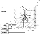
- FIG. 1 is a schematic cross-sectional view showing the configuration of the atomizing device 100 according to the first embodiment.
- FIG. 2 is a perspective view showing a member 130 included in the atomizing device 100 according to the first embodiment.
- the control unit 150 is shown as a functional block.
- the control unit 150 is controllably connected to the ultrasonic vibrator 120 and the supply unit 140 by a control line or the like, and controls each device.
- the control unit 150 is realized by, for example, a microcomputer (microcontroller) or the like, and is arranged inside an outer shell housing (not shown) of the atomizing device 100.
- the control unit 150 may be attached to the outside of an outer housing (not shown), for example.
- the atomizing device 100 is a mist generating device that mistizes (atomicizes) the liquid 200 to generate a mist 220 having a floating property floating in the atmosphere.
- the atomizing device 100 is provided (formed) on the member 130 by using a sound wave (hereinafter referred to as a beam 230) emitted from the ultrasonic vibrator 120 by ultrasonic vibration of the ultrasonic vibrator 120.
- a liquid column 210 made of liquid 200 is ejected from the spout 132.
- Innumerable mist 220 is emitted from the surface of the liquid column 210 ejected from the ejection port 132.
- the atomizer 100 generates mist 220.
- the mist 220 is one of a plurality of liquid particles in which the liquid 200 is mist-ized.
- the atomizing device 100 is used, for example, in a humidifying device, a deodorizing device, a sterilizing device, or the like.
- the liquid 200 is water, but any liquid such as oil may be used. Further, the liquid 200 may contain a fragrance component, a bactericidal component, or the like. For example, when the liquid 200 contains a fragrance component, the atomizer 100 is a scent generator that generates a mist 220 containing the fragrance component. Alternatively, for example, when the liquid 200 contains a sterilizing component such as hypochlorous acid, the atomizing device 100 is a sterilizing device.
- the mist 220 is, for example, fine liquid particles having a diameter on the order of micrometers and has plankton floating in the atmosphere.
- the average diameter of the number of mist 220 is about several ⁇ m.
- the average diameter of the number of mist 220 is 1.5 ⁇ m or less.
- the atomizing device 100 includes an accommodating body 110, an ultrasonic vibrator 120, a member 130, a supply unit 140, and a control unit 150.
- the container 110 is a container that holds the liquid 200 and has an open upper part.
- the housing 110 supports the ultrasonic vibrator 120 and the member 130.
- the material used for the housing 110 is, for example, a resin material, but is not particularly limited.
- the accommodating body 110 is provided with, for example, a liquid phase portion 111 in which the liquid 200 is accommodated and a gas phase portion 112 in which the liquid 200 is not accommodated.
- the ultrasonic oscillator 120 is an oscillator for applying ultrasonic vibration to the liquid 200.
- the ultrasonic vibrator 120 has a plurality of resonance points (resonance frequencies). Specifically, the ultrasonic vibrator 120 has a resonance point that vibrates at a resonance frequency higher than the fundamental resonance frequency in addition to the fundamental resonance frequency (first-order resonance frequency).
- the ultrasonic vibrator 120 vibrates ultrasonically by applying a voltage to the control unit 150 (more specifically, the drive control unit 152).
- the ultrasonic vibrator 120 is, for example, a piezoelectric element.
- the ultrasonic transducer 120 is arranged at the bottom of the housing 110 so as to emit a beam 230 in the positive direction of the Z axis by vibrating in the Z axis direction.
- the member 130 is arranged in the direction in which the beam 230 is emitted from the ultrasonic vibrator 120 (in the present embodiment, the Z-axis positive direction side of the ultrasonic vibrator 120).
- the member 130 is provided with a through hole 131 having a beam 230 emitted by the ultrasonic vibrator 120 and a through hole 131 having an outlet 132 for passing the liquid 200 propagating through the beam 230 and ejecting the liquid 200 in a columnar shape.
- the through hole 131 is provided in the member 130 so as to extend in the direction in which the beam 230 emitted by the ultrasonic vibrator 120 propagates.
- the ejection port 132 ejects a liquid column 210 made of a liquid 200 that has passed through the through hole 131 and propagates through the beam 230 emitted by the ultrasonic vibrator 120.
- the member 130 has a tubular shape, more specifically, a square shape (horn shape) having a through hole 131 and a spout 132 at the center.
- the hole diameter of the through hole 131 is gradually reduced toward the side where the ultrasonic vibrator 120 emits the beam 230 (in the present embodiment, the Z-axis positive direction side).
- the inner wall 134 also referred to as the inner surface or the wall portion
- the inner wall 134 has, for example, a tapered shape inclined with respect to the direction in which the ultrasonic vibrator 120 emits the beam 230 (in the present embodiment, the Z-axis direction). It is an inclined part that is the surface of.
- the beam 230 is reflected on the inner surface of the member 130 and focused (sound collected) in the vicinity of the ejection port 132.
- the spout 132 is an opening for ejecting the liquid 200 so as to form a liquid column 210.
- the ratio of the lower hole diameter of the through hole 131 (the opening on the side where the liquid 200 is introduced into the through hole 131) and the upper hole diameter of the through hole 131 (that is, the hole diameter of the ejection port 132) is particularly high. Not limited.
- the hole diameter of the ejection port 132 is about 1 mm
- the width of the liquid column 210 is about 1 mm.
- the shape of the openings of the through hole 131 and the spout 132 is, for example, circular, but may be square, rectangular, oval, or the like.
- the end 133 (more specifically, the end face) on the side where the ejection port 132 of the member 130 is provided is, for example, water repellent.
- the peripheral end 133 of the spout 132 in the member 130 is water repellent.
- a material such as a fluoride such as a film having water repellency may be provided on the end portion 133, or the surface of the end portion 133 of the member 130 may be processed to have water repellency.
- the member 130 may be realized by a material such as fluoride having water repellency.
- the end portion 133 located around the ejection port 132 in the member 130 has water repellency. That is, in the member 130, for example, at least the end 133 on the side of the member 130 on which the ejection port 132 is formed has water repellency.
- the member 130 is arranged so that the end portion 133 located around the spout 132 is located at the gas phase portion 112. That is, the end portion 133 of the member 130 on the side where the ejection port 132 is formed is located at the gas phase portion 112 of the accommodating body 110.
- the supply unit 140 which will be described later, supplies the liquid 200 to the housing 110 so that the end portion 133 is not immersed in the liquid 200.
- the member 130 may be arranged in the housing 110 so that the end 133 is located above the opening located above the housing 110.
- the material used for the member 130 is not particularly limited.
- the material used for the member 130 is a resin material.
- a reflective material that reflects the beam 230 may be used.
- the supply unit 140 is a water supply unit that supplies the liquid 200 to the accommodating body 110.
- the supply unit 140 includes, for example, an electromagnetic valve for switching supply / non-supply of the liquid 200 to the accommodating body 110, and a pipe through which the liquid 200 passes.
- the supply unit 140 (more specifically, the solenoid valve included in the supply unit 140) is controlled by, for example, the control unit 150 (more specifically, the supply control unit 151) to supply / non-supply as described above. Is switched.
- the supply unit 140 is connected to, for example, a tank or the like (not shown) in which the liquid 200 that is the source of the mist 220 sprayed from the atomizer 100 is stored, and the liquid 200 supplied from the tank or the like is supplied to the supply control unit 151. Supply / non-supply can be switched to supply to the housing 110 under the control of.
- the control unit 150 is a control device that controls the overall operation of the atomizing device 100. Specifically, the control unit 150 controls the operation of the ultrasonic vibrator 120 and the supply unit 140.
- the control unit 150 includes a supply control unit 151 and a drive control unit 152.
- the supply control unit 151 is a processing unit for controlling the operation of the supply unit 140.
- the supply control unit 151 controls the solenoid valve included in the supply unit 140 to cause the supply unit 140 to supply the liquid 200 to the accommodating body 110.
- the atomizing device 100 is housed in a time measuring unit such as an RTC (Real Time Lock) or an accommodating body 110 in order to measure the time in order to control the supply amount of the liquid 200 to be supplied to the liquid 200 by the supply unit 140.
- a measuring device such as a water level sensor for measuring the amount of the liquid 200 or a flow meter for measuring the amount of the liquid 200 flowing through the supply unit 140 may be provided.
- the supply control unit 151 may control the supply unit 140 based on the measurement result of the measuring device. For example, the supply control unit 151 causes the supply unit 140 to supply the liquid 200 to the container 110 so that the end portion 133 is not immersed in the liquid 200.
- the drive control unit 152 is a processing unit that oscillates (drives) the ultrasonic vibrator 120. Specifically, the drive control unit 152 oscillates the ultrasonic vibrator 120 at a resonance frequency higher than the primary resonance frequency of the ultrasonic vibrator 120. For example, the drive control unit 152 controls the timing of applying a voltage to the ultrasonic vibrator 120, the magnitude of the voltage, the frequency, and the like.
- FIG. 3 is a diagram showing an example of the impedance characteristics of the ultrasonic vibrator 120.
- the horizontal axis of the graph shown in FIG. 3 is the frequency of the voltage (for example, AC voltage) applied to the ultrasonic vibrator 120
- the vertical axis is the impedance of the ultrasonic vibrator 120 at the frequency of the applied voltage. be.
- the primary resonance frequency of the ultrasonic vibrator 120 is 2.5 MHz.
- the third-order resonance frequency of the ultrasonic vibrator 120 is 8.2 MHz.
- the fifth-order resonance frequency of the ultrasonic vibrator 120 is 13.7 MHz.
- the ultrasonic transducer 120 has a plurality of resonance points.
- FIG. 4 is a diagram showing the particle size of the mist 220 with respect to the vibration frequency applied to the liquid 200.
- the particle size of the mist 220 with respect to the vibration frequency applied to the liquid 200 is expressed by the Lang formula shown in the following formula (1).
- d p is the particle size of the mist 220
- k is the proportional coefficient obtained experimentally
- ⁇ is the density of the liquid 200
- f is the vibration given to the liquid 200. It is a frequency
- ⁇ is the surface tension of the liquid 200.
- the graph shown in FIG. 4 shows the particle size of the mist 220 with respect to the frequency given to the liquid 200 when the liquid 200 is water and the Lang equation is used.
- the drive control unit 152 oscillates the ultrasonic vibrator 120 at a high-order resonance frequency exceeding 5 MHz.
- the drive control unit 152 can generate the liquid column 210 and generate the mist 220 having a particle size of 1.5 ⁇ m or less from the liquid column 210 by controlling the ultrasonic vibrator 120.
- the drive control unit 152 oscillates the ultrasonic vibrator 120 at a resonance frequency higher than the first-order resonance frequency of the ultrasonic vibrator 120 (third-order in the present embodiment). Specifically, the drive control unit 152 applies a voltage having a high-order resonance frequency that vibrates in the alignment direction of the ultrasonic vibrator 120 and the member 130 to the ultrasonic vibrator 120 to obtain a high-order resonance frequency.
- the ultrasonic oscillator 120 is vibrated with.
- the drive control unit 152 controls the ultrasonic vibrator 120 to generate a liquid column 210 and generate a mist 220 having a particle size of about 1 ⁇ m from the liquid column 210.
- the control unit 150 is realized by, for example, a microcontroller or the like. Specifically, the control unit 150 has a communication interface for communicating with the ultrasonic transducer 120 and the supply unit 140, a non-volatile memory in which the program is stored, and a volatile storage area for executing the program. It is realized by sexual memory, input / output port, processor that executes programs, etc.
- the control unit 150 may be realized by a dedicated electronic circuit that executes each operation. Further, the control unit 150 may include, for example, a step-up power supply circuit including a converter and the like.
- the drive control unit 152 generates a voltage having a higher resonance frequency of the above-mentioned ultrasonic vibrator 120 based on a power received from an external power source (not shown) such as a commercial power source, and ultrasonically vibrates the generated voltage. By applying it to the child 120, the ultrasonic vibrator 120 is vibrated at a higher resonance frequency.
- an external power source not shown
- the ultrasonic vibrator 120 is vibrated at a higher resonance frequency.
- the atomizing device 100 may further include a blower for transporting the mist 220 into the space.
- the blower unit is, for example, a fan such as a DC (Direct Current) fan.
- the blower unit conveys the mist 220 emitted from the liquid column 210 in a direction away from the accommodating body 110 by generating an air flow toward the outside of the accommodating body 110.
- the position where the blower is arranged may be inside the accommodating body 110 or outside the accommodating body 110, and is not particularly limited.
- the atomizing device 100 includes an ultrasonic vibrator 120 having a plurality of resonance points, a drive control unit 152 for oscillating the ultrasonic vibrator 120, and an ultrasonic vibrator.
- the beam 230 emitted by the 120 and the member 130 provided with the through hole 131 having the ejection port 132 for passing the liquid 200 propagating through the beam 230 and ejecting the liquid 200 in a columnar shape are provided.
- the drive control unit 152 oscillates the ultrasonic vibrator 120 at a resonance frequency higher than the primary resonance frequency of the ultrasonic vibrator 120.
- the drive control unit 152 oscillates the ultrasonic vibrator 120 at a higher-order resonance point, that is, a higher-order resonance frequency among a plurality of resonance points of the ultrasonic vibrator 120. Therefore, the drive control unit 152 can vibrate the ultrasonic vibrator 120 at a frequency required to make the particle size of the mist 220, for example, about 1 ⁇ m.
- the liquid column 210 having an appropriate diameter is ejected by appropriately setting the size of the ejection port 132. If the member 130 is not provided, a liquid column 210 having a large diameter is generated. As the diameter of the liquid column 210 increases, the vibration energy per unit volume in the liquid column 210 decreases.
- the amount of mist 220 generated is significantly reduced, or the mist 220 is not emitted from the liquid column 210. Therefore, by making the liquid column 210 having an appropriate diameter ejected from the ejection port 132 by the member 130, the vibration energy transmitted to the surface of the liquid column 210 is increased. As a result, the decrease in the amount of mist 220 generated is suppressed. From the above, according to the atomizing device 100, the particle size of the mist 220 can be controlled to an appropriate size, and the decrease in the amount of mist 220 generated can be suppressed.
- the drive control unit 152 oscillates the ultrasonic vibrator 120 at a high-order resonance frequency exceeding 5 MHz.
- the particle size of the mist 220 can be reduced to about 1 ⁇ m as shown in FIG. Therefore, for example, the diffusivity of the mist 220 can be improved as compared with the case where the particle size of the mist 220 is 10 ⁇ m or more, and the collision probability with bacteria and malodorous gas located in the space is improved. be able to.
- the atomizing device 100 further includes an accommodating body 110 provided with a liquid phase portion 111 in which the liquid 200 is accommodated and a gas phase portion 112 in which the liquid 200 is not accommodated.
- the member 130 is arranged so that the end portion 133 located around the ejection port 132 is located at the gas phase portion 112.
- the diameter of the liquid column 210 is further adjusted to an appropriate size. Easy to set.
- the end portion 133 located around the ejection port 132 in the member 130 has water repellency.
- the atomizing device 100 continues to generate the mist 220, it is possible to suppress the liquid 200 from adhering to the end portion 133. If the liquid 200 adheres (wets) to the end portion 133, the diameter of the liquid column 210 may become large or the formation of the liquid column 210 may become unstable. This may reduce the amount of mist 220 generated. Therefore, since the end portion 133 has water repellency, the diameter of the liquid column 210 can be stabilized, so that it is possible to further suppress a decrease in the amount of mist 220 generated.
- FIG. 5 is a schematic cross-sectional view showing the configuration of the atomizing device 100a according to the modified example of the first embodiment.
- the atomizing device 100a includes an accommodating body 110, an ultrasonic vibrator 120, a member 130, a supply unit 140, and a control unit 150.
- the member 130 is tilted. Specifically, in the member 130, the hole axis of the ejection port 132 (in this modification, the extending direction of the through hole 131 and the axis parallel to the hole axis of the through hole 131) is in the vertical direction (in the present implementation). In the form, it is arranged in the housing 110 so as to intersect with the Z-axis direction). As a result, the extending direction of the liquid column 210 ejected from the ejection port 132 intersects with the vertical direction. That is, the ejection port 132 is provided on the member 130 so that the extending direction of the liquid column 210 intersects the vertical direction. In other words, the spout 132 is provided on the member 130 so that the extending direction of the liquid column 210, which is the columnar liquid 200 ejected from the spout 132, intersects the vertical direction.
- the weight of the liquid column 210 is less likely to be applied to the liquid column 210.
- the extending direction of the liquid column 210 is a direction parallel to the vertical direction
- the upper portion weight of the liquid column 210 is added to the lower portion of the liquid column 210. Therefore, if the extending direction of the liquid column 210 is a direction parallel to the vertical direction, it is difficult for the liquid column 210 to be formed due to the weight of the liquid column 210. In this way, the liquid column 210 that has lost its momentum immediately after being ejected from the ejection port 132 returns to the vicinity of the original ejection port 132 due to its own weight, dropping, etc., so that the diameter of the liquid column 210 is unsatisfactory.
- the member 130 is tilted with respect to the atomizing device 100 according to the first embodiment and arranged in the accommodating body 110, but the ejection port 132 has a vertical direction in which the liquid column 210 extends. It may be provided on the member 130 so as to intersect the direction.
- the member may have a through hole whose hole axis is parallel to the vertical direction and a spout that communicates with the through hole and whose hole axis intersects the vertical direction.
- the member may be formed so that the hole axis of the ejection port 132 intersects the hole axis of the through hole 131 in the posture of the member 130 according to the first embodiment.
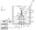
- FIG. 6 is a schematic cross-sectional view showing the configuration of the atomizing device 101 according to the second embodiment.
- the atomizing device 101 includes an accommodating body 110, an ultrasonic vibrator 120, a member 130, a supply unit 140, a control unit 150, and a sound collecting unit 160. As described above, the atomizing device 101 further includes a sound collecting unit 160 in addition to the configuration of the atomizing device 100.
- the sound collecting unit 160 is an acoustic lens in which a sound wave (beam 230) emitted by an ultrasonic vibrator 120 is incident, and the incident beam 230 is passed through a through hole 131 and focused on a predetermined focal point 240. That is, the predetermined focal point 240 is the focal point of the sound collecting unit 160.
- the predetermined focal point 240 is located at (i) the spout 132, or (ii) farther than the spout 132 when viewed from the sound collecting unit 160.
- the sound collecting unit 160 is a transmissive acoustic lens located between the ultrasonic vibrator 120 and the member 130, and is transmitted through and emitted from the incident beam 230.
- the exit surface 170 of the sound collecting unit 160 that emits the beam 230 is concave.
- the member 130 is arranged at a position facing the emission surface 170.
- the incident surface on which the beam 230 is incident in the sound collecting unit 160 is arranged in contact with the ultrasonic vibrator 120. As a result, it is possible to suppress the attenuation due to the interference of the beam 230 between the ultrasonic vibrator 120 and the sound collecting unit 160, and the generation of fine bubbles generated by cavitation.
- the size of the sound collecting unit 160 may be arbitrary.
- the sound collecting unit 160 covers the ultrasonic vibrator 120 and has the same size or ultrasonic waves as the ultrasonic vibrator 120 when viewed along the traveling direction of the beam 230 emitted from the ultrasonic vibrator 120. It is larger than the oscillator 120.
- FIG. 7 is a diagram for explaining the relationship between the diameter W1 of the ejection port 132 and the beam diameter W2.
- the diameter W1 of the ejection port 132 is larger than the beam diameter W2 of the beam 230 focused on the sound collecting unit 160.
- the diameter W1 of the ejection port 132 is larger than the beam diameter W2 at a predetermined focal point 240 of the beam 230 focused on the sound collecting unit 160. That is, at a predetermined focal point 240, the beam 230 is focused so that the beam diameter W2 is smaller than the diameter W1 of the ejection port 132.
- the sound collecting unit 160 is formed so that the beam diameter W2 at a predetermined focal point 240 of the beam 230 is smaller than the diameter W1 of the ejection port 132.
- a is a proportional coefficient which is an arbitrary numerical value
- ⁇ is the wavelength of the beam 230
- D is the diameter of the ultrasonic transducer 120
- F is the focal length of the sound collecting unit 160.
- the diameter W1 of the ejection port 132 is 10 times or less the beam diameter W2. Specifically, for example, the diameter W1 of the ejection port 132 is larger than the beam diameter W2 and 10 times or less the beam diameter W2. More specifically, the diameter W1 of the ejection port 132 is larger than the beam diameter W2 and 10 times or less the beam diameter W2 at a predetermined focal point 240.
- the inner wall 134 of the member 130 in other words, the inner wall 134 forming the through hole 131 in the member 130 emits the beam 230 in the sound collecting portion 160 (that is, the exit surface 170).
- the beam 230 is arranged so as to be located outside the path of the beam 230 that focuses up to a predetermined focal point 240. That is, in the ultrasonic vibrator 120, the member 130, and the sound collecting unit 160, the beam 230 does not come into contact with the member 130 from the exit surface 170 that emits the beam 230 in the sound collecting unit 160 to the predetermined focal point 240.
- the shape, arrangement, and the like are set.
- the drive control unit 152 applies a voltage having a high-order resonance frequency that vibrates in the alignment direction of the ultrasonic vibrator 120 and the sound collecting unit 160 to the ultrasonic vibrator 120 to obtain a high-order resonance frequency.
- the ultrasonic vibrator 120 is vibrated.
- the beam 230 is emitted from the ultrasonic transducer 120 toward the sound collecting unit 160.
- the beam 230 emitted from the ultrasonic transducer 120 passes through the sound collecting unit 160 and is emitted so as to be focused at a predetermined focal point 240.
- the beam 230 emitted from the sound collecting unit 160 passes through the through hole 131 and the ejection port 132 so as not to come into contact with the inner wall 134 of the member 130.
- the loss of vibration energy due to reflection by the inner wall 134 of the member 130 is suppressed to the liquid column 210, and the beam 230 collected by the sound collecting unit 160 is transmitted.
- the material used for the sound collecting unit 160 is not particularly limited as long as it has transparency with respect to the beam 230 (for example, the property of transmitting the beam 230 by 70% or more).
- the material used for the sound collecting unit 160 is, for example, a resin material such as polycarbonate.
- the atomizing device 101 has the ultrasonic vibrator 120, the drive control unit 152, and the ejection port 132, similarly to the atomizing device 100 according to the first embodiment.
- a member 130 provided with a through hole 131 is provided.
- the atomizing device 101 further emits the incident beam 230 so that the beam 230 emitted by the ultrasonic transducer 120 is incident and passes through the through hole 131 to be focused on a predetermined focal point 240.
- the sound unit 160 is provided.
- the predetermined focal point 240 is located at (i) the spout 132, or (ii) farther than the spout 132 when viewed from the sound collecting unit 160.
- the beam 230 emitted from the ultrasonic transducer 120 is focused at the position where the liquid column 210 is formed.
- the vibration energy of the beam 230 can be appropriately transmitted to the liquid column 210. Therefore, it is possible to further easily generate mist 220 from the liquid column 210.
- the sound collecting unit 160 is located between the ultrasonic vibrator 120 and the member 130, and transmits and emits the incident beam 230.
- the sound collecting unit 160 may be realized by a transmission type acoustic lens that transmits and focuses the beam 230. According to this, the sound collecting unit 160 can focus the beam 230 with a simple configuration.
- the exit surface 170 that emits the beam 230 in the sound collecting unit 160 is concave.
- the beam 230 can be focused. can.
- the sound collecting unit 160 is in contact with the ultrasonic vibrator 120 so that the surface of the sound collecting unit 160 facing the ultrasonic vibrator 120 is orthogonal to the traveling direction of the beam 230. Have been placed.
- the interference of the beam 230 between the ultrasonic vibrator 120 and the sound collecting unit 160 is suppressed. Therefore, the decrease in the vibration energy of the beam 230 due to the generation of bubbles due to the interference of the beam 230 is suppressed.
- the diameter W1 of the ejection port 132 is larger than the beam diameter W2 of the beam 230 focused on the sound collecting unit 160.
- the beam 230 can pass through the through hole 131 and the ejection port 132 provided in the member 130 without contacting the member 130. Therefore, the vibration energy of the beam 230 can be transmitted to the liquid column 210 without lowering the vibration energy of the beam 230 by the member 130.
- the diameter W1 of the ejection port 132 is 10 times or less the beam diameter W2 of the beam 230 focused on the sound collecting unit 160.
- the diameter of the liquid column 210 depends on the diameter W1 of the spout 132. For example, if the diameter W1 of the ejection port 132 is increased, the diameter of the liquid column 210 is also increased. Here, if the diameter W1 of the ejection port 132 is too larger than the beam diameter W2, the vibration energy of the beam 230 is difficult to be transmitted to the liquid column 210 (more specifically, the surface of the liquid column 210). Therefore, by making the diameter W1 of the ejection port 132 10 times or less the beam diameter W2, the vibration energy of the beam 230 can be appropriately transmitted to the liquid column 210.
- the member 130 is located outside the path of the beam 230 in which the inner wall 134 of the member 130 focuses from the surface (exit surface 170) at which the beam 230 is emitted to the predetermined focal point 240. Arranged to do.
- the beam 230 can pass through the through hole 131 and the ejection port 132 provided in the member 130 without contacting the member 130. Therefore, the vibration energy of the beam 230 can be transmitted to the liquid column 210 without lowering the vibration energy of the beam 230 by the member 130.
- FIG. 8 is a schematic cross-sectional view showing the configuration of the atomizing device 102 according to the third embodiment.
- the atomizing device 102 includes an accommodating body 110, an ultrasonic vibrator 120, a member 130, a supply unit 140, a control unit 150, and a sound collecting unit 161. As described above, the atomizing device 102 further includes a sound collecting unit 161 in addition to the configuration of the atomizing device 100.
- the sound collecting unit 161 is an acoustic lens in which a sound wave (beam 230) emitted by an ultrasonic vibrator 120 is incident, and the incident beam 230 is passed through a through hole 131 and focused on a predetermined focal point 240. That is, the predetermined focal point 240 is the focal point of the sound collecting unit 161.
- the predetermined focal point 240 is located at (i) the spout 132, or (ii) farther than the spout 132 when viewed from the sound collecting unit 161.
- the sound collecting unit 161 is a member having reflectivity to the beam 230 emitted by reflecting the incident beam 230 (that is, a reflective acoustic lens).
- the reflecting surface 171 that reflects the beam 230 in the sound collecting unit 161 is a paraboloid surface (paraboloidal shape).
- the diameter W1 of the ejection port 132 is larger than the beam diameter W2 of the beam 230 focused on the sound collecting unit 161.
- the diameter W1 of the ejection port 132 is larger than the beam diameter W2 at a predetermined focal point 240 of the beam 230 focused on the sound collecting unit 161. That is, at a predetermined focal point 240, the beam 230 is focused so that the beam diameter W2 is smaller than the diameter W1 of the ejection port 132.
- the sound collecting unit 161 is formed so that the beam diameter W2 at a predetermined focal point 240 of the beam 230 is smaller than the diameter W1 of the ejection port 132.
- a is a proportional coefficient which is an arbitrary numerical value
- ⁇ is the wavelength of the beam 230
- D is the diameter of the ultrasonic transducer 120
- F is the focal length of the sound collecting unit 161.
- the diameter W1 of the ejection port 132 is 10 times or less the beam diameter W2. Specifically, for example, the diameter W1 of the ejection port 132 is larger than the beam diameter W2 and 10 times or less the beam diameter W2. More specifically, the diameter W1 of the ejection port 132 is larger than the beam diameter W2 and 10 times or less the beam diameter W2 at a predetermined focal point 240.
- the inner wall 134 of the member 130 in other words, the inner wall 134 forming the through hole 131 in the member 130 emits the beam 230 in the sound collecting portion 161 (that is, the reflecting surface 171).
- the beam 230 is arranged so as to be located outside the path of the beam 230 that focuses up to a predetermined focal point 240. That is, in the ultrasonic vibrator 120, the member 130, and the sound collecting unit 161, the beam 230 does not come into contact with the member 130 from the reflecting surface 171 that reflects the beam 230 in the sound collecting unit 161 to the predetermined focal point 240.
- the shape, arrangement, and the like are set.
- the drive control unit 152 applies a voltage having a high-order resonance frequency that vibrates in the alignment direction of the ultrasonic vibrator 120 and the sound collecting unit 161 to the ultrasonic vibrator 120 to obtain a high-order resonance frequency.
- the ultrasonic vibrator 120 is vibrated.
- the beam 230 is emitted from the ultrasonic transducer 120 toward the sound collecting unit 161.
- the beam 230 emitted from the ultrasonic transducer 120 is reflected by the sound collecting unit 161 so as to be focused at a predetermined focal point 240, and is emitted from the sound collecting unit 161.
- the beam 230 emitted from the sound collecting unit 161 passes through the through hole 131 and the ejection port 132 so as not to come into contact with the inner wall 134 of the member 130. As a result, the loss of vibration energy due to reflection by the inner wall 134 of the member 130 is suppressed to the liquid column 210, and the beam 230 collected by the sound collecting unit 161 is transmitted.
- the material used for the sound collecting unit 161 may be not particularly limited as long as it has reflectivity with respect to the beam 230 (for example, the property of reflecting the beam 230 by 90% or more).
- the material used for the sound collecting unit 161 is, for example, a metal material such as stainless steel (stainless steel / SUS), but is not particularly limited.
- the atomizing device 102 has the ultrasonic vibrator 120, the drive control unit 152, and the ejection port 132, similarly to the atomizing device 100 according to the first embodiment.
- a member 130 provided with a through hole 131 is provided.
- the atomizing device 102 further emits the incident beam 230 so that the beam 230 emitted by the ultrasonic transducer 120 is incident and passes through the through hole 131 to be focused on a predetermined focal point 240.
- the sound unit 161 is provided.
- the predetermined focal point 240 is located at (i) the spout 132, or (ii) farther than the spout 132 when viewed from the sound collecting unit 161.
- the beam 230 emitted from the ultrasonic transducer 120 is focused at the position where the liquid column 210 is formed.
- the vibration energy of the beam 230 can be appropriately transmitted to the liquid column 210. Therefore, it is possible to further easily generate mist 220 from the liquid column 210.
- the sound collecting unit 161 emits by reflecting the incident beam 230.
- the sound collecting unit 161 may be realized by a reflection type acoustic lens that reflects and focuses the beam 230. According to this, the sound collecting unit 161 can focus the beam 230 with a simple configuration.
- the reflecting surface 171 that reflects the incident beam 230 in the sound collecting unit 161 is a paraboloid.
- the beam 230 can be focused. can.
- the sound collecting unit 161 is in contact with the ultrasonic vibrator 120 so that the surface of the sound collecting unit 161 facing the ultrasonic vibrator 120 is orthogonal to the traveling direction of the beam 230. Have been placed.
- the interference of the beam 230 between the ultrasonic vibrator 120 and the sound collecting unit 161 is suppressed. Therefore, the decrease in the vibration energy of the beam 230 due to the generation of bubbles due to the interference of the beam 230 is suppressed.
- the diameter W1 of the ejection port 132 is larger than the beam diameter W2 of the beam 230 focused on the sound collecting unit 161.
- the beam 230 can pass through the through hole 131 and the ejection port 132 provided in the member 130 without contacting the member 130. Therefore, the vibration energy of the beam 230 can be transmitted to the liquid column 210 without lowering the vibration energy of the beam 230 by the member 130.
- the diameter W1 of the ejection port 132 is 10 times or less the beam diameter W2 of the beam 230 focused on the sound collecting unit 161.
- the diameter of the liquid column 210 depends on the diameter W1 of the spout 132. For example, if the diameter of the ejection port 132 is increased, the diameter of the liquid column 210 is also increased. Here, if the diameter W1 of the ejection port 132 is too larger than the beam diameter W2, the vibration energy of the beam 230 is difficult to be transmitted to the liquid column 210 (more specifically, the surface of the liquid column 210). Therefore, by making the diameter W1 of the ejection port 132 10 times or less the beam diameter W2, the vibration energy of the beam 230 can be appropriately transmitted to the liquid column 210.
- the member 130 is located outside the path of the beam 230 in which the inner wall 134 of the member 130 focuses from the surface (reflection surface 171) at which the beam 230 is emitted in the sound collecting unit 161 to a predetermined focal point 240. Arranged to do.
- the beam 230 can pass through the through hole 131 and the ejection port 132 provided in the member 130 without contacting the member 130. Therefore, the vibration energy of the beam 230 can be transmitted to the liquid column 210 without lowering the vibration energy of the beam 230 by the member 130.
- the external shape of the member 130 is tubular, but the present invention is not limited to this.
- the member 130 may be provided with a through hole 131 and a spout 132, and may have an external shape such as a plate shape.
- the liquid 200 may be tap water for humidification or cooling, an aqueous liquid containing hypochlorous acid having an effect of sterilization or the like, an oily liquid containing a fragrance or the like, or the like.
- control unit 150 may further include a time measuring unit for measuring time such as an RTC.
- control unit 150 may generate the mist 220 at a predetermined time.
- the member 130 is used as the atomization device 100a according to the modification of the first embodiment. You may tilt it. Specifically, in the configuration of the atomizing device 101 according to the second embodiment or the atomizing device 102 according to the third embodiment, the member 130 is further arranged so that the hole axis of the ejection port 132 intersects the vertical direction. , May be placed in the enclosure 110. As a result, the effect that the liquid column 210 is easily formed can be further enjoyed.
- all or a part of the components of the control unit 150 such as the supply control unit 151 and the drive control unit 152 may be configured by dedicated hardware, or each component may be configured. It may be realized by executing a software program suitable for the above. Even if each component is realized by a program execution unit such as a CPU (Central Processing Unit) or a processor reading and executing a software program recorded on a recording medium such as an HDD (Hard Disk Drive) or a semiconductor memory. good.
- a program execution unit such as a CPU (Central Processing Unit) or a processor reading and executing a software program recorded on a recording medium such as an HDD (Hard Disk Drive) or a semiconductor memory. good.
- the component of the control unit 150 may be composed of one or a plurality of electronic circuits.
- the one or more electronic circuits may be general-purpose circuits or dedicated circuits, respectively.
- One or more electronic circuits may include, for example, a semiconductor device, an IC (Integrated Circuit), an LSI (Large Scale Integration), or the like.
- the IC or LSI may be integrated on one chip or may be integrated on a plurality of chips. Here, it is called IC or LSI, but the name changes depending on the degree of integration, and it may be called system LSI, VLSI (Very Large Scale Integration), or ULSI (Ultra Large Scale Integration).
- FPGA Field Programmable Gate Array programmed after manufacturing the LSI can also be used for the same purpose.
- the general or specific aspects of the present disclosure may be realized by a system, an apparatus, a method, an integrated circuit or a computer program.
- a computer-readable non-temporary recording medium such as an optical disk, HDD or semiconductor memory in which the computer program is stored.
- it may be realized by any combination of a system, an apparatus, a method, an integrated circuit, a computer program and a recording medium.
Landscapes
- Engineering & Computer Science (AREA)
- Physics & Mathematics (AREA)
- Acoustics & Sound (AREA)
- Multimedia (AREA)
- Mechanical Engineering (AREA)
- Special Spraying Apparatus (AREA)
Priority Applications (1)
| Application Number | Priority Date | Filing Date | Title |
|---|---|---|---|
| JP2022553520A JP7599098B2 (ja) | 2020-09-30 | 2021-08-11 | 霧化装置 |
Applications Claiming Priority (4)
| Application Number | Priority Date | Filing Date | Title |
|---|---|---|---|
| JP2020165397 | 2020-09-30 | ||
| JP2020165416 | 2020-09-30 | ||
| JP2020-165416 | 2020-09-30 | ||
| JP2020-165397 | 2020-09-30 |
Publications (1)
| Publication Number | Publication Date |
|---|---|
| WO2022070622A1 true WO2022070622A1 (ja) | 2022-04-07 |
Family
ID=80949915
Family Applications (1)
| Application Number | Title | Priority Date | Filing Date |
|---|---|---|---|
| PCT/JP2021/029586 Ceased WO2022070622A1 (ja) | 2020-09-30 | 2021-08-11 | 霧化装置 |
Country Status (2)
| Country | Link |
|---|---|
| JP (1) | JP7599098B2 (https=) |
| WO (1) | WO2022070622A1 (https=) |
Citations (6)
| Publication number | Priority date | Publication date | Assignee | Title |
|---|---|---|---|---|
| JPS5461309A (en) * | 1977-10-21 | 1979-05-17 | Tdk Electronics Co Ltd | Ultrasonic wave liquid atomizer |
| JPS56107421U (https=) * | 1980-01-19 | 1981-08-20 | ||
| JPS60132670A (ja) * | 1983-12-19 | 1985-07-15 | Matsushita Electric Ind Co Ltd | 霧化装置 |
| JP2003038646A (ja) * | 2001-08-02 | 2003-02-12 | Olympus Optical Co Ltd | 医用噴霧装置 |
| JP2006130393A (ja) * | 2004-11-04 | 2006-05-25 | Honda Electronic Co Ltd | 超音波霧化装置 |
| JP2020000995A (ja) * | 2018-06-28 | 2020-01-09 | 株式会社ディスコ | 超音波水噴射装置 |
Family Cites Families (4)
| Publication number | Priority date | Publication date | Assignee | Title |
|---|---|---|---|---|
| JPS5434113A (en) * | 1977-08-22 | 1979-03-13 | Mitsubishi Electric Corp | Supersonic atomizer |
| JPS59354A (ja) * | 1982-06-23 | 1984-01-05 | Matsushita Electric Ind Co Ltd | 霧化装置 |
| JP2008221134A (ja) | 2007-03-13 | 2008-09-25 | Matsushita Electric Ind Co Ltd | ミスト発生装置 |
| JP5743265B2 (ja) | 2011-06-17 | 2015-07-01 | 株式会社オプトニクス精密 | 霧化噴霧装置 |
-
2021
- 2021-08-11 WO PCT/JP2021/029586 patent/WO2022070622A1/ja not_active Ceased
- 2021-08-11 JP JP2022553520A patent/JP7599098B2/ja active Active
Patent Citations (6)
| Publication number | Priority date | Publication date | Assignee | Title |
|---|---|---|---|---|
| JPS5461309A (en) * | 1977-10-21 | 1979-05-17 | Tdk Electronics Co Ltd | Ultrasonic wave liquid atomizer |
| JPS56107421U (https=) * | 1980-01-19 | 1981-08-20 | ||
| JPS60132670A (ja) * | 1983-12-19 | 1985-07-15 | Matsushita Electric Ind Co Ltd | 霧化装置 |
| JP2003038646A (ja) * | 2001-08-02 | 2003-02-12 | Olympus Optical Co Ltd | 医用噴霧装置 |
| JP2006130393A (ja) * | 2004-11-04 | 2006-05-25 | Honda Electronic Co Ltd | 超音波霧化装置 |
| JP2020000995A (ja) * | 2018-06-28 | 2020-01-09 | 株式会社ディスコ | 超音波水噴射装置 |
Also Published As
| Publication number | Publication date |
|---|---|
| JPWO2022070622A1 (https=) | 2022-04-07 |
| JP7599098B2 (ja) | 2024-12-13 |
Similar Documents
| Publication | Publication Date | Title |
|---|---|---|
| Yasui | Acoustic cavitation | |
| JP3386050B2 (ja) | 噴霧装置 | |
| Simon et al. | Ultrasonic atomization of liquids in drop-chain acoustic fountains | |
| JP4326955B2 (ja) | 超音波音響エネルギを液体流内に合焦させる装置 | |
| JPWO2010150629A1 (ja) | 弾性表面波を用いる霧または微細気泡の発生方法および霧または微細気泡発生装置 | |
| JP7017472B2 (ja) | 分析セル、及び分析ユニット | |
| JP4990707B2 (ja) | 超音波霧発生装置 | |
| JP6539468B2 (ja) | 超音波霧化装置 | |
| SG188535A1 (en) | Improved ultrasonic cleaning method and apparatus | |
| JP5392753B2 (ja) | 霧化装置及びそれを用いた霧化方法 | |
| JP2008173624A (ja) | 霧化装置 | |
| JP7599098B2 (ja) | 霧化装置 | |
| JP5279740B2 (ja) | 超音波霧化装置及びそれを備えた設備機器 | |
| JP2000271517A (ja) | 超音波噴霧装置 | |
| JP2005111328A (ja) | 携帯用超音波霧化装置 | |
| JP2020065944A (ja) | 静電霧化装置 | |
| JP2016221460A (ja) | 超音波霧化装置 | |
| TW200900167A (en) | Ultrasonic rinsing device and ultrasonic rinsing method | |
| JP7333935B2 (ja) | ミスト供給装置 | |
| JP4812657B2 (ja) | 超音波霧化装置及びそれを備えた設備機器 | |
| US20150076245A1 (en) | Device for nebulizing a liquid | |
| JP2001358108A (ja) | 基板処理装置 | |
| JP5592734B2 (ja) | 超音波洗浄装置及び超音波洗浄方法 | |
| JPH04207800A (ja) | 超音波霧化装置 | |
| JPS6340148B2 (https=) |
Legal Events
| Date | Code | Title | Description |
|---|---|---|---|
| 121 | Ep: the epo has been informed by wipo that ep was designated in this application |
Ref document number: 21874925 Country of ref document: EP Kind code of ref document: A1 |
|
| ENP | Entry into the national phase |
Ref document number: 2022553520 Country of ref document: JP Kind code of ref document: A |
|
| NENP | Non-entry into the national phase |
Ref country code: DE |
|
| 122 | Ep: pct application non-entry in european phase |
Ref document number: 21874925 Country of ref document: EP Kind code of ref document: A1 |