WO2022070531A1 - 画像処理装置、画像処理装置の作動方法、画像処理装置の作動プログラム - Google Patents
画像処理装置、画像処理装置の作動方法、画像処理装置の作動プログラム Download PDFInfo
- Publication number
- WO2022070531A1 WO2022070531A1 PCT/JP2021/023595 JP2021023595W WO2022070531A1 WO 2022070531 A1 WO2022070531 A1 WO 2022070531A1 JP 2021023595 W JP2021023595 W JP 2021023595W WO 2022070531 A1 WO2022070531 A1 WO 2022070531A1
- Authority
- WO
- WIPO (PCT)
- Prior art keywords
- resolution
- image
- tomographic
- pixel
- interest
- Prior art date
- Legal status (The legal status is an assumption and is not a legal conclusion. Google has not performed a legal analysis and makes no representation as to the accuracy of the status listed.)
- Ceased
Links
Images


Classifications
-
- G—PHYSICS
- G06—COMPUTING OR CALCULATING; COUNTING
- G06T—IMAGE DATA PROCESSING OR GENERATION, IN GENERAL
- G06T5/00—Image enhancement or restoration
- G06T5/50—Image enhancement or restoration using two or more images, e.g. averaging or subtraction
-
- A—HUMAN NECESSITIES
- A61—MEDICAL OR VETERINARY SCIENCE; HYGIENE
- A61B—DIAGNOSIS; SURGERY; IDENTIFICATION
- A61B6/00—Apparatus or devices for radiation diagnosis; Apparatus or devices for radiation diagnosis combined with radiation therapy equipment
- A61B6/02—Arrangements for diagnosis sequentially in different planes; Stereoscopic radiation diagnosis
- A61B6/025—Tomosynthesis
-
- A—HUMAN NECESSITIES
- A61—MEDICAL OR VETERINARY SCIENCE; HYGIENE
- A61B—DIAGNOSIS; SURGERY; IDENTIFICATION
- A61B6/00—Apparatus or devices for radiation diagnosis; Apparatus or devices for radiation diagnosis combined with radiation therapy equipment
- A61B6/50—Apparatus or devices for radiation diagnosis; Apparatus or devices for radiation diagnosis combined with radiation therapy equipment specially adapted for specific body parts; specially adapted for specific clinical applications
- A61B6/502—Apparatus or devices for radiation diagnosis; Apparatus or devices for radiation diagnosis combined with radiation therapy equipment specially adapted for specific body parts; specially adapted for specific clinical applications for diagnosis of breast, i.e. mammography
-
- A—HUMAN NECESSITIES
- A61—MEDICAL OR VETERINARY SCIENCE; HYGIENE
- A61B—DIAGNOSIS; SURGERY; IDENTIFICATION
- A61B6/00—Apparatus or devices for radiation diagnosis; Apparatus or devices for radiation diagnosis combined with radiation therapy equipment
- A61B6/52—Devices using data or image processing specially adapted for radiation diagnosis
- A61B6/5211—Devices using data or image processing specially adapted for radiation diagnosis involving processing of medical diagnostic data
- A61B6/5217—Devices using data or image processing specially adapted for radiation diagnosis involving processing of medical diagnostic data extracting a diagnostic or physiological parameter from medical diagnostic data
-
- G—PHYSICS
- G06—COMPUTING OR CALCULATING; COUNTING
- G06T—IMAGE DATA PROCESSING OR GENERATION, IN GENERAL
- G06T3/00—Geometric image transformations in the plane of the image
- G06T3/40—Scaling of whole images or parts thereof, e.g. expanding or contracting
-
- G—PHYSICS
- G06—COMPUTING OR CALCULATING; COUNTING
- G06T—IMAGE DATA PROCESSING OR GENERATION, IN GENERAL
- G06T3/00—Geometric image transformations in the plane of the image
- G06T3/40—Scaling of whole images or parts thereof, e.g. expanding or contracting
- G06T3/4053—Scaling of whole images or parts thereof, e.g. expanding or contracting based on super-resolution, i.e. the output image resolution being higher than the sensor resolution
-
- G—PHYSICS
- G06—COMPUTING OR CALCULATING; COUNTING
- G06T—IMAGE DATA PROCESSING OR GENERATION, IN GENERAL
- G06T7/00—Image analysis
- G06T7/0002—Inspection of images, e.g. flaw detection
- G06T7/0012—Biomedical image inspection
-
- A—HUMAN NECESSITIES
- A61—MEDICAL OR VETERINARY SCIENCE; HYGIENE
- A61B—DIAGNOSIS; SURGERY; IDENTIFICATION
- A61B6/00—Apparatus or devices for radiation diagnosis; Apparatus or devices for radiation diagnosis combined with radiation therapy equipment
- A61B6/04—Positioning of patients; Tiltable beds or the like
- A61B6/0407—Supports, e.g. tables or beds, for the body or parts of the body
- A61B6/0414—Supports, e.g. tables or beds, for the body or parts of the body with compression means
-
- G—PHYSICS
- G06—COMPUTING OR CALCULATING; COUNTING
- G06T—IMAGE DATA PROCESSING OR GENERATION, IN GENERAL
- G06T2207/00—Indexing scheme for image analysis or image enhancement
- G06T2207/10—Image acquisition modality
- G06T2207/10072—Tomographic images
-
- G—PHYSICS
- G06—COMPUTING OR CALCULATING; COUNTING
- G06T—IMAGE DATA PROCESSING OR GENERATION, IN GENERAL
- G06T2207/00—Indexing scheme for image analysis or image enhancement
- G06T2207/10—Image acquisition modality
- G06T2207/10072—Tomographic images
- G06T2207/10112—Digital tomosynthesis [DTS]
-
- G—PHYSICS
- G06—COMPUTING OR CALCULATING; COUNTING
- G06T—IMAGE DATA PROCESSING OR GENERATION, IN GENERAL
- G06T2207/00—Indexing scheme for image analysis or image enhancement
- G06T2207/20—Special algorithmic details
- G06T2207/20212—Image combination
-
- G—PHYSICS
- G06—COMPUTING OR CALCULATING; COUNTING
- G06T—IMAGE DATA PROCESSING OR GENERATION, IN GENERAL
- G06T2207/00—Indexing scheme for image analysis or image enhancement
- G06T2207/20—Special algorithmic details
- G06T2207/20212—Image combination
- G06T2207/20221—Image fusion; Image merging
-
- G—PHYSICS
- G06—COMPUTING OR CALCULATING; COUNTING
- G06T—IMAGE DATA PROCESSING OR GENERATION, IN GENERAL
- G06T2207/00—Indexing scheme for image analysis or image enhancement
- G06T2207/30—Subject of image; Context of image processing
- G06T2207/30004—Biomedical image processing
- G06T2207/30068—Mammography; Breast
-
- G—PHYSICS
- G06—COMPUTING OR CALCULATING; COUNTING
- G06T—IMAGE DATA PROCESSING OR GENERATION, IN GENERAL
- G06T2207/00—Indexing scheme for image analysis or image enhancement
- G06T2207/30—Subject of image; Context of image processing
- G06T2207/30004—Biomedical image processing
- G06T2207/30096—Tumor; Lesion
Definitions
- a technique for obtaining a plurality of tomographic images on an arbitrary tomographic surface of a subject such as tomosynthesis imaging in which the subject is irradiated with radiation from a plurality of different irradiation angles, is known.
- the structure of the subject extending in the depth direction in which the tomographic planes are lined up can be separated and visualized for each tomographic image. Therefore, it is possible to depict a structure of interest such as a lesion, which was difficult to depict with a simple two-dimensional image.
- a simple two-dimensional image is a projection image obtained by irradiating a subject with radiation from one irradiation angle in which a radiation source is directly opposed to a radiation detector.
- the method of increasing the resolution of the composite two-dimensional image has the following problems. That is, when the structure of interest extends in the depth direction of the subject, in the composite two-dimensional image, the detailed forms of the structure of interest drawn in a state of being separated into different tomographic images are overlapped by the composition. Therefore, the detailed morphological information depicted in each tomographic image is partially lost in the composite two-dimensional image. Even if the resolution of such a composite two-dimensional image is increased, it may not be possible to express the detailed form of the structure of interest reflected in the tomographic image in detail.
- the load of data processing such as the processing time for increasing the resolution increases.
- the amount of data increases, so that the load of data processing such as the increase of the memory capacity and the lengthening of the transfer time in the data processing also increases.
- the processor performs the region selection process in each of the plurality of tomographic images.
- a representative value representing the feature amount of the region of interest is derived, the representative values are compared between the tomographic images for each region of interest corresponding to the coordinate position, and one or more tomographic images are selected based on the comparison result of the representative values. Then, in the selected tomographic image, it is preferable to select the target area centering on the pixel of interest.
- the processor generates a low-resolution composite two-dimensional image having the first resolution by synthesizing a plurality of tomographic images having the first resolution in the depth direction in which the fault planes are lined up, and in the composite two-dimensional image generation process.
- a high-resolution composite two-dimensional image can be generated by synthesizing a magnified image in which the number of pixels of a low-resolution composite two-dimensional image is increased to the number of pixels corresponding to the second resolution and a high-resolution partial image. preferable.
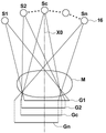
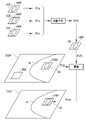
- the radiation source 16 is housed inside the radiation irradiation unit 14.
- the radiation source 16 emits radiation such as ⁇ -rays and X-rays.
- the timing of irradiating radiation from the radiation source 16 and the radiation generation conditions in the radiation source 16, that is, the selection of the material of the target and the filter, the tube voltage, the irradiation time, and the like are controlled by the console 2.
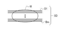
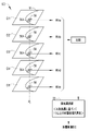
- the tomographic image group SD a plurality of tomographic images Dj are arranged along the depth direction of the tomographic plane in the breast M.
- the coordinate positions of each pixel in each tomographic plane correspond to each other.
- pixels having the same coordinate position in the tomographic plane are referred to as corresponding pixels.
- the tomographic image Dj has the first resolution.
- the first resolution is the resolution of the projected image Gi output by the radiation detector 15, and the in-fault plane in the three-dimensional space set when the tomographic image group SD is reconstructed from the projected image Gi by the back projection method or the like. It is determined according to the number of coordinate positions.
- the image processing apparatus 4 generates a high-resolution synthetic two-dimensional image CG2 having a higher resolution than the synthetic two-dimensional image CG1 in addition to the synthetic two-dimensional image CG1. Therefore, in the following, the composite two-dimensional image CG1 generated by the first synthesis unit 31 is referred to as a low-resolution composite two-dimensional image CG1.
- the target region OR may be a part of a plurality of tomographic images Dj, a part of the tomographic images Dj included in the plurality of tomographic images Dj (for example, two out of ten tomographic images Dj).
- the target region OR may be set in the entire area of the tomographic image Dj.
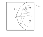
- the region selection unit 32 selects the region including the structure of interest 40 in the tomographic image Dj as the target region OR.
- the region selection unit 32 detects the structure of interest 40 of the breast M using the low-resolution synthetic two-dimensional image CG1.
- the structure of interest 40 is, specifically, as shown in FIG. 10, a tumor 41, a spicula 42, a calcification 43, a line structure 44, and the like contained in the breast M.
- the line structure 44 is a mammary gland such as a leaflet or a milk duct.
- the region selection unit 32 may detect all of the tumor 41, the spicula 42, the calcification 43, and the line structure 44, or may detect at least one of them. Which interest structure 40 is to be detected is appropriately set.
- the super-resolution method is not limited to the method described in the above-mentioned Japanese Patent Application Laid-Open No. 2020-0257886.
- any high-order interpolation method such as nearest neighbor interpolation, bilinear interpolation, and bicubic interpolation can be used.
- it is also possible to use a method of extracting a small region (called a patch) that repeatedly appears from an image and super-resolution the original image using the pixel values of the extracted small region. can.
- the image of the target region OR in the tomographic images D2 to D4 is regarded as a three-dimensional image, and k-neighborhood interpolation is performed using k pixels located closest to the pixel to be interpolated in the target region OR of the tomographic image D3. .. Any value such as 6 or 26 can be used as the value of k.
- the method for increasing the resolution includes the projection used when reconstructing the tomographic image group SD as shown in FIG. There is a method of using image Gi.
- a method for increasing the resolution of the target area OR a method using a projected image Gi instead of the super-resolution method may be applied.
- a well-known back projection method such as a simple back projection method is used, and an image of the target region OR selected in the tomographic image Dj is obtained from the projected image Gi as a high-resolution partial image HRP. It is a method of reconstructing as.
- back projection using four projected images G1 to G4 will be described.
- the pixel value of the coordinate position P100 on a certain tomographic surface Tj in the breast M is calculated by back-projecting the pixel values of the corresponding coordinate positions in the projected images G1 to G4.
- the second compositing unit 34 executes a compositing two-dimensional image generation process for generating a high-resolution composite two-dimensional image CG2 having a second resolution by using the high-resolution partial image HRP.
- the second compositing unit 34 includes an enlarged image CGM in which the number of pixels of the low-resolution composite two-dimensional image CG1 having the first resolution is increased to the number of pixels corresponding to the second resolution, and a high-resolution image CGM.
- the magnified image CGM has a second resolution because it is combined with the high resolution partial image HRP.
- the enlarged image CGM is generated using the low-resolution composite two-dimensional image CG1 having the first resolution. That is, the second compositing unit 34 tentatively converts the low-resolution composite two-dimensional image CG1 into a second resolution by increasing the resolution to the second resolution by the super-resolution method in the compositing two-dimensional image generation process. Generates a high-resolution composite 2D image of. Then, the second compositing unit 34 synthesizes the enlarged image CGM which is a temporary high-resolution composite two-dimensional image and the high-resolution partial image HRP to obtain the high-resolution composite two-dimensional image CG2 having the second resolution. Generate.
- the second synthesis unit 34 adds and averages the pixel values PVa, PVb, and PVc of each pixel at the coordinate positions P4 and P5 to obtain the pixel value PVH. Derived. As a method of synthesizing each pixel, instead of the addition average, the pixel values PVa, PVb, and PVc of each pixel may be simply added within a range that does not saturate. Further, a weighted addition average may be used in which each pixel of each high-resolution partial image HRP is weighted and the weighted pixel values are added and averaged.
- a plurality of high-resolution partial image HRPs may have different sizes and shapes. In that case, there is a portion where the plurality of high-resolution partial image HRPs do not overlap in the depth direction of the tomographic plane Tj. Except for such overlapping portions, the pixel value of any one of the plurality of high-resolution partial image HRPs is set as the pixel value PVCG2 of the high-resolution composite two-dimensional image CG2.
- the pixel value PVa of the high-resolution partial image HRP of the tomographic plane T1 is set to the pixel value PVCG2 of the high-resolution composite two-dimensional image CG2 at the coordinate position P1.
- the target region OR is a region including the interest structure 40
- the high-resolution partial image HRP is generated only for the region including the interest structure 40. It is not generated for other areas. Therefore, in the region where the high-resolution partial image HRP is not synthesized in the magnified image CGM, such as the magnified region RM shown in FIG. 15, the temporary pixel value PVp of the magnified image CGM becomes the pixel value PVCG2 of the high-resolution composite two-dimensional image CG2. Become.
- the display control unit 35 displays the high-resolution composite two-dimensional image CG2 generated by the second composite unit 34 on the display 24.
- Reference numeral 50 is an example of a display screen 50 on which the high-resolution composite two-dimensional image CG2 is displayed on the display 24.
- the first synthesis unit 31 synthesizes a plurality of tomographic images Dj in the tomographic image group SD to perform low-resolution synthesis.
- a two-dimensional image CG1 is generated, and the generated low-resolution composite two-dimensional image CG1 is displayed on the display 24 (step S2000).
- the image processing apparatus 4 has a higher resolution than the first resolution.
- the process for generating the high-resolution composite two-dimensional image CG2 having the resolution of 2 is started.
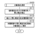
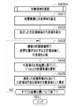
- the area selection unit 32 executes an area selection process for selecting a target area OR whose resolution is to be increased (step S4000).
- step S6120 the second compositing unit 34 synthesizes the enlarged image CGM, which is a temporary high-resolution composite two-dimensional image, and the high-resolution partial image HRP by the methods shown in FIGS. 14 to 16. As a result, a high-resolution composite two-dimensional image CG2 is generated.
- the image processing apparatus 4 represents a part of the tomographic image group SD including the plurality of tomographic images Dj having the first resolution and representing each of the plurality of tomographic planes Tj of the subject. , Area selection processing to select as the target area OR to make the second resolution higher than the first resolution, and high resolution to generate a high resolution partial image HRP by increasing the resolution of the target area OR to the second resolution.
- the processing and the synthetic two-dimensional image generation processing for generating the high-resolution synthetic two-dimensional image CG2 having the second resolution are executed by using the high-resolution partial image HRP.
- the tomographic image group SD is used. Compared with the case where all of the plurality of tomographic images Dj included are increased in resolution, the load of data processing such as processing time, storage capacity, and transfer time for increasing the resolution can be suppressed.
- the high resolution is finer than the case where the low resolution composite two-dimensional image CG1 having the first resolution is made high resolution.
- a composite two-dimensional image CG2 is obtained.
- the structure of interest 40 extending in the depth direction is separated and depicted, so that the tomographic image Dj having the first resolution is a high-resolution partial image in which the resolution is increased to the second resolution.
- the detailed form of the structure of interest 40 can be expressed more finely than in the case of increasing the resolution of the low-resolution composite two-dimensional image CG1. This is because the low-resolution composite two-dimensional image CG1 synthesizes a plurality of tomographic images Dj having the first resolution, so that the detailed morphological information of the structure 40 of interest drawn in each tomographic image Dj is lost. I will be broken.
- the high-resolution partial image HRP which is a high-resolution tomographic image
- the detailed morphology of the structure of interest 40 is expressed more finely than in the low-resolution tomographic image Dj. Therefore, it is better to synthesize the high-resolution partial image HRP to generate the high-resolution composite two-dimensional image CG2 than to directly increase the resolution of the low-resolution composite two-dimensional image CG1. Since the amount is large, the detailed form of the structure of interest 40 can be expressed more accurately. Therefore, as described above, a finer high-resolution composite two-dimensional image CG2 can be obtained as compared with the case where the low-resolution composite two-dimensional image CG1 is made higher in resolution.
- the calcification 43 exists over a plurality of tomographic planes Tj having different depths as the structure of interest 40
- the tomographic image Dj of each tomographic plane Tj is synthesized
- the multiple tomographic planes Tj are obtained.
- the shapes of a plurality of existing calcifications 43 may overlap and be drawn as a single mass of calcifications 43 on the low-resolution synthetic two-dimensional image CG1. If the tomographic image Dj is high-resolution and then synthesized as in the technique of the present disclosure, the synthesis is performed after the shape of the calcification 43 of each tomographic surface Tj is reproduced in high definition.
- the shape of the calcification 43 of each tomographic surface Tj is compared with the case of increasing the resolution of the low-resolution composite two-dimensional image CG1. Can be expressed more accurately.
- the area selection unit 32 selects an area including the structure of interest 40 as the target area OR for generating the high-resolution partial image HRP. Since the interest structure 40 has a high degree of attention in diagnosis such as image interpretation, the high-resolution synthetic two-dimensional image CG2 displaying the interest structure 40 in detail is highly useful in diagnosis.
- the tumor 41, the calcification 43, the spicula 42, and the line structure 44 is set as the structure of interest to be detected 40.
- About a few percent of the mass 41 may be malignant.
- Spicula 42 is a characteristic finding in hard cancer and invasive lobular carcinoma.
- Calcification 43 can become cancerous.
- the line structure 44 is prone to lesions such as mass 41, spicula 42, and calcification 43. Therefore, if at least one of the tumor 51, the spicula 42, the calcification 43, and the line structure 44 is the structure of interest 40, a high-resolution synthetic two-dimensional image CG2 useful for diagnosing the breast can be obtained.
- the area selection unit 32 detects the structure of interest 40 using the low-resolution composite two-dimensional image CG1 in the area selection process.
- the low-resolution composite two-dimensional image CG1 is often generated and displayed at the initial stage of the image interpretation work. Be done. Therefore, as a workflow for interpreting images, for example, a workflow in which a low-resolution composite two-dimensional image CG1 is observed, the presence or absence of an interest structure 40 is determined, and if there is an interest structure 40, a fine image of that portion is observed. Can be considered.
- the low-resolution composite two-dimensional image CG1 as the detection source of the structure of interest 40 is suitable for such a workflow. Further, since the low-resolution composite two-dimensional image CG1 has a smaller amount of data than the tomographic image group SD, the detection of the interest structure 40 is performed as compared with the case where the interest structure 40 is detected using the tomographic image group SD. It can be done in a short time.
- the second compositing unit 34 includes an enlarged image CGM in which the number of pixels of the low-resolution composite two-dimensional image CG1 is increased to the number of pixels corresponding to the second resolution in the compositing two-dimensional image generation process.
- a high-resolution composite two-dimensional image CG2 is generated by synthesizing the high-resolution partial image HRP.
- the enlarged image CGM based on the low-resolution composite two-dimensional image CG1 can be used for the regions other than the high-resolution partial image HRP, so that the other regions may be generated from the tomographic image Dj. In comparison, the processing time can be reduced.
- the second compositing unit 34 is a temporary high-resolution composite two-dimensional image in which the low-resolution composite two-dimensional image CG1 is converted to a second resolution as an enlarged image CGM in the composite two-dimensional image generation process.
- a high-resolution composite two-dimensional image CG2 is generated by generating an image and synthesizing a temporary high-resolution composite two-dimensional image and a high-resolution partial image HRP. Therefore, in the high-resolution composite two-dimensional image CG2, the region other than the high-resolution partial image HRP can be expressed in finer detail as compared with the simply enlarged image of the low-resolution composite two-dimensional image CG1.
- an image obtained by simply magnifying the low-resolution composite two-dimensional image CG1 such as the simple enlarged image MGP shown in FIG. 12 may be used. .. Even in this case, a fine expression can be obtained for the portion where the high-resolution partial image HRP is used.
- step S6000A shown in FIG. 21 is executed instead of step S6000 shown in FIG. As shown in FIG.
- the second compositing unit 34 generates a high-resolution composite two-dimensional image CG2 using only a plurality of high-resolution partial image HRPs in the compositing two-dimensional image generation process (step S6000A) (step S6210). ).
- the comparison result is the result of which pixel has the largest pixel value or which pixel has the smallest pixel value. Based on such a comparison result, one pixel having the maximum or minimum pixel value is extracted. This process is performed for each pixel in the undetected area.
- a part of the tomographic image D4 is selected for a certain target area OR2, and a part of the tomographic image D5 is selected for another target area OR2.
- the target area OR2 is shown as an area including a plurality of pixels, but the target area OR2 is selected for each pixel.
- the target region OR2 is selected in the selected tomographic image Dj.
- a plurality of tomographic images Dj may be selected based on the comparison result of the pixel values. For example, there is a case where two are selected, a tomographic image Dj having the pixel with the largest pixel value and a tomographic image Dj having the pixel with the second largest pixel value.
- the processing in this case is as follows, for example.
- the target region OR2 is selected in each of the selected tomographic images Dj. Then, a high-resolution partial image HRP is generated for each target region OR2. In this case, a plurality of high-resolution partial image HRPs having corresponding coordinate positions and different depths are generated even in the undetected region.
- the pixel value PVH after synthesizing is obtained by adding and averaging the pixel values of the pixels corresponding to the coordinate positions. Derived. Then, the derived pixel value PVH is used as the pixel value PVCG2 of the high-resolution composite two-dimensional image CG2.
- simple addition may be performed within a range in which the pixel values of each pixel are not saturated.
- a weighted addition average may be used in which each pixel of each high-resolution partial image HRP is weighted and the weighted pixel values are added and averaged.
- the entire area of the high-resolution composite two-dimensional image CG2 is generated using a plurality of high-resolution partial image HRPs in which a part of the plurality of tomographic images Dj is high-resolution. Therefore, a high-resolution composite two-dimensional image CG2 having a fine image quality in the entire area including the undetected region can be obtained as compared with the first embodiment using the enlarged image CGM for the undetected region.
- the tomographic image Dj is selected for each pixel, and the selected pixel is selected as the target area OR2. The load is reduced.
- the third embodiment mainly differs from the first embodiment and the second embodiment in the method of selecting the target area OR.
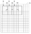
- the target region OR is selected by setting the region of interest 56 for each tomographic image Dj.
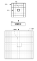
- FIG. 23 shows a region of interest 56 set in the tomographic image Dj, using a part of the tomographic image Dj as an example.
- the region of interest 56 is a region having a preset size centered on the pixel of interest 56A, with one pixel in the tomographic image Dj as the pixel of interest 56A.
- the size of the region of interest 56 is set to the size of 5 ⁇ 5 pixels centered on the pixel of interest 56A.
- the area of interest 56 is an area for extracting local features in each tomographic image Dj, and for extracting the features for each area of interest 56, for example, a filter to which a filter having the same size as the area of interest 56 is applied is applied. It is done by processing.
- the size of the region of interest 56 in this example is an example, and may be another size.
- the area selection unit 32 sets the area of interest 56 for each pixel in the tomographic image Dj while shifting the pixel of interest 56A pixel by pixel in one tomographic image Dj. Then, a representative value RV representing the feature amount for each set attention region 56 is derived.
- the region selection unit 32 performs a process of deriving the representative value RV for all the tomographic images Dj included in the tomographic image group SD. As a result, a representative value RV representing a local feature amount is derived for each region of interest 56 for the entire area of each tomographic image Dj.
- the representative value RV is, for example, a dispersion value of the pixel values of the pixels included in the region of interest 56.
- the region selection unit 32 compares the representative value RV for each attention region 56 corresponding to one coordinate position Pj among the plurality of tomographic images Dj, and uses the comparison result of the representative value RV. Based on, one or more tomographic images Dj are selected.
- the region selection unit 32 compares these representative values RVa, RVb, RVc, RVd, RVe, and ... Select one D2.
- the area selection unit 32 executes a selection process of the tomographic image Dj based on the representative value RV for each coordinate position Pj in the tomographic surface Tj.
- the area selection unit 32 selects the target area OR centering on the pixel of interest 56A in the tomographic image D2 selected based on the representative value RV.
- the size of the area of interest 56 is 5 ⁇ 5 pixels, while the size of the target area OR is 7 ⁇ 7 pixels, which is larger than the area of interest 56.
- the size of the target area OR may be the same as that of the area of interest 56. However, since the target area OR is a target for high resolution, it needs to have a size necessary for high resolution. Since the tomographic image Dj is selected for each coordinate position Pj, the area selection unit 32 selects the target area OR for each coordinate position Pj.
- the reason why the dispersion value is used as the representative value RV of the attention region 56 is that the larger the dispersion value, the larger the concentration change in the attention region 56, and the region where the structure such as the interest structure 40 is drawn. This is because there is a high possibility. Then, by selecting the tomographic image Dj having a large variance value of the region of interest 56 for each coordinate position Pj, it is possible to select the region in which the structure of interest 40 or the like is drawn as the target region OR. On the other hand, the undetected tomographic image Dj in which the structure of interest 40 is not detected can be excluded from the selection target of the target region OR.
- the high-resolution unit 33 increases the resolution of the selected target area OR to a second resolution by using the above-mentioned super-resolution method or the like.
- Generate a resolution partial image HRP In the example shown in FIG. 26, a high-resolution partial image HRP having a size of 14 ⁇ 14 pixels is generated from a target area OR having a size of 7 ⁇ 7 pixels.
- the attention pixel 56A in the target area OR becomes an area having a size equivalent to four pixels in the high resolution partial image HRP, and here, this area is referred to as an enlarged attention pixel 56AM.
- step S4000A shown in FIG. 28 instead of step S4000 shown in FIG.
- the region selection unit 32 sets the region of interest 56 in each of the plurality of tomographic images Dj (step S4310).
- the region selection unit 32 derives a representative value RV representing the feature amount for each set region of interest 56 in each of the plurality of tomographic images Dj (step S4320).
- the area selection unit 32 compares the representative value RV for each of the attention area 56 corresponding to the coordinate position Pj among the plurality of tomographic images Dj.
- the region selection unit 32 selects one or more tomographic images Dj (one in this example) based on the comparison result of the representative value RV.
- step S4350 as shown in FIG. 25, the region selection unit 32 selects a region including the region of interest 56 in the selected tomographic image Dj as the target region OR. Such selection of the target region OR is repeated for all the coordinate positions Pj (step S4360).
- the high resolution unit 33 executes the same process as in step S5000 of FIG. In this example, a high-resolution partial image HRP corresponding to the target region OR shown in FIG. 26 is generated.
- the second synthesis unit 34 executes the same processing as in step S6000A of FIG. 21 of the second embodiment. As shown in FIG. 27, the second synthesizing unit 34 generates a high-resolution composite two-dimensional image CG2 by synthesizing only a plurality of generated high-resolution partial image HRPs.
- the attention region 56 is set in the tomographic image Dj, the representative value RV representing the feature amount of the attention region 56 is derived, and the target region OR is based on the derived representative value RV.
- the region of interest 56 is set for each pixel in the tomographic image Dj, a representative value RV representing the feature amount can be derived over the entire area in the tomographic image Dj. Therefore, the feature amount in the tomographic image Dj can be used for selecting the target region OR without omission.
- the variance value of the region of interest 56 is used as the representative value RV, it is easy to select the region in which the structure of interest 40 is drawn as the target region OR as described above.
- an average value may be used instead of the variance value.
- a minimum value, a maximum value, an intermediate value, or the like may be used as the representative value RV.
- one tomographic image Dj is selected based on the representative value RV, such that one tomographic image Dj having the maximum variance value is selected for each region of interest 56, but a plurality of tomographic images Dj are selected instead of one.
- the area selection unit 32 may select a predetermined number of tomographic images Dj based on the order of the representative value RV in the area selection process, and select the target area OR for each selected tomographic image Dj. ..
- the region selection unit 32 selects two tomographic images Dj up to the top two of the representative value RV. In this case, two tomographic images Dj are selected for each region of interest 56 corresponding to one coordinate position Pj.
- two tomographic images Dj are selected for each region of interest 56 corresponding to one coordinate position Pj.
- the attention pixel 56A which is the center of the attention region 56, is the enlarged attention pixel 56AM.
- the target region OR is selected for each tomographic image Dj selected. (Represented by high resolution partial image HRP in FIG. 29) is selected.
- the tomographic image Dj of the tomographic plane T3 and the tomographic plane T4 is selected, and the target region OR is selected for each of the selected tomographic images Dj.
- a predetermined number of tomographic images Dj may be selected based on the rank of the representative value RV, and the target region OR may be selected for each selected tomographic image Dj. If the predetermined number is 2 or more, a plurality of tomographic images Dj will be selected. By doing so, it becomes easier to extract the features of the tomographic structure 40 extending in the depth direction of the tomographic surface Tj, as compared with the case of selecting one tomographic image Dj for each region of interest 56.
- the second synthesis unit 34 simply adds and averages a plurality of high-resolution partial image HRPs, but as in the modified examples shown in FIGS. 30 to 32. , Each pixel of the high-resolution partial image HRP may be weighted and then weighted addition averaging may be performed.
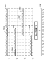
- the second synthesis unit 34 generates a high-resolution composite two-dimensional image CG2 by executing the composite two-dimensional image generation process of step S6000B shown in FIG. 30 instead of the step S6000 shown in FIG. do.
- a value obtained by multiplying the pixel value of each pixel by the weight coefficient set for each is calculated, and the calculated value is obtained for a plurality of pixels corresponding to the coordinate position Pj. Is added and averaged.
- the coefficient of the weight of the pixel corresponding to the fault plane T1 is "1.00”
- the coefficient of the weight of the pixel corresponding to the fault plane T2 is "0.30”
- the coefficient of the weight of the pixel corresponding to the fault plane T3 corresponds to the fault plane T3.
- the pixel weighting factor is "0.70”
- the pixel weighting factor corresponding to the tomographic surface T4 is also "0.70".
- the weight is maximum for the enlarged attention pixel 56AM corresponding to the attention pixel 56A, and becomes smaller toward the periphery when the magnified attention pixel 56AM is the center.
- Each high resolution partial image HRP is selected based on the representative value RV of the region of interest 56. Therefore, in the overlapping portion where the plurality of high-resolution composite two-dimensional images CG2 having different depths overlap, the features of the portion close to the region of interest 56 are more than the peripheral features and are reflected in the high-resolution composite two-dimensional image CG2. Is preferable.
- the fault plane T1 corresponds to the enlarged attention pixel 56AM corresponding to the region of interest 56, but in the fault planes T2 to T4 other than the fault plane T1, not the enlarged attention pixel 56AM but the surrounding pixels correspond. are doing. Therefore, it is preferable that the pixel value PVCG2 of the high-resolution composite two-dimensional image CG2 at the coordinate position P8 reflects more of the pixel value of the enlarged attention pixel 56AM on the tomographic surface T1.
- the features of the portion close to the region of interest 56 can be reflected in the high-resolution composite two-dimensional image CG2 more than the features of the periphery.
- the weight as shown in FIG. 33 may be set in place of or in addition to the weight shown in FIG.
- the weight in FIG. 33 is a weight corresponding to a representative value RV representing a feature amount for each region of interest 56, and is an example of a “second weight” according to the technique of the present disclosure.
- the high-resolution partial image HRP is generated for each target region OR selected based on the representative value RV of the region of interest 56.
- the weight shown in FIG. 33 is set according to the magnitude of the representative value RV. For example, when a variance value is used as the representative value RV, the larger the variance value, the larger the weight.
- the weight of FIG. 33 is not set for each pixel as in the weight shown in FIG. 31, but only one is set for the high-resolution partial image HRP.
- the representative value RV is “10” and the weight is “10”, and the representative value RV is “5” and the weight is “5”.
- the second compositing unit 34 generates a high-resolution composite two-dimensional image CG2 by adding and averaging each pixel of the high-resolution partial image HRP with such weights.
- the characteristics of the high-resolution partial image HRP having a large representative value RV can be reflected more in the high-resolution composite two-dimensional image CG2.
- Either one of the first weight shown in FIG. 31 and the second weight shown in FIG. 33 may be used, or both may be used.
- the area selection unit 32 sets the interval between the attention pixels 56A in the area selection process.
- the area of interest 56 having a size of m ⁇ m may be set at intervals of n or more pixels.
- n is a natural number of 1 or more
- m is a natural number of 3 or more
- the condition of m> n is satisfied.
- the target area OR is selected and the high-resolution partial image HRP is generated.
- the composite two-dimensional image generation process for generating the high-resolution composite two-dimensional image CG2 using the high-resolution partial image HRP is as shown in FIG. 36.
- FIG. 36 is an example in which the attention pixel 56A is set with an interval of two pixels as shown in FIG. 34.
- the high-resolution partial image HRP is not generated for each enlarged attention pixel 56AM corresponding to the attention pixel 56A, but is generated at intervals of the pixels.
- the region of interest 56 is set so as to satisfy the condition of m> n, any high-resolution partial image HRP exists at all the coordinate positions Pj. That is, in the high-resolution composite two-dimensional image CG2, there is no gap portion between pixels in which the high-resolution partial image HRP does not exist.
- the attention area 56 is set so as to satisfy the condition of m> n, as shown in FIG.
- the adjacent attention areas 56 are adjacent to each other. There is no gap between 56. Therefore, since all the pixels in the tomographic image Dj are included in any of the attention areas 56, the characteristics of all the pixels of the tomographic image Dj can be reflected in the selection of the target area OR.
- a region of interest 56 is set for a region (indicated by hatching) in which a breast M, which is an example of a subject, exists, and other regions such as a blank region are set. It is not necessary to set the region of interest 56. If the area of interest 56 is set for at least the area where the subject exists, the minimum necessary area can be made high-definition. As the area for setting the area of interest 56 is reduced, the load of data processing is also reduced.
- the attention area 56 is set for each pixel in the region where the breast M exists, and the attention region 56 is spaced apart from the other regions such as the blank area. May be set.
- the image quality is maintained by performing processing for each pixel, while some processing of other areas such as the blank area is performed. By omitting it, the processing time can be shortened.
- the target area OR is a rectangular area, but the present invention is not limited to this.
- the target area OR may have a shape other than a rectangle such as a circle. Further, when the interest structure 40 is detected, the shape of the target region OR may be matched with the outer shape of the detected interest structure 40.
- the tomographic image Dj obtained by tomosynthesis imaging is exemplified, but the present invention is not limited to this.
- CT Computer Planar Tomography
- PET Positron Emission Tomography
- SPECT Single Photon Emission Tomography
- MRI Magnetic Image imaging
- MRI Magnetic Image
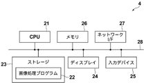
- a processing unit that executes various processes such as an image acquisition unit 30, a first composition unit 31, a region selection unit 32, a high resolution unit 33, a second composition unit 34, and a display control unit 35.
- various processors Processors
- CPU 21 which is a general-purpose processor that executes software (image processing program 22) and functions as various processing units
- FPGA Field Programmable Gate Array
- a processor having a circuit configuration specially designed to execute a specific process such as a programmable logic device (PLC), an ASIC (Application Specific Integrated Circuit), which is a processor whose circuit configuration can be changed later. Dedicated electric circuit etc. are included.
- PLC programmable logic device
- ASIC Application Specific Integrated Circuit
- One processing unit may be composed of one of these various processors, or may be a combination of two or more processors of the same type or different types (for example, a combination of a plurality of FPGAs and / or a CPU). It may be configured in combination with FPGA). Further, a plurality of processing units may be configured by one processor.
- one processor is combined with one or more CPUs and software. There is a form in which this processor functions as a plurality of processing units.
- SoC System On Chip
- the various processing units are configured by using one or more of the above-mentioned various processors as a hardware-like structure.
- an electric circuit in which circuit elements such as semiconductor elements are combined can be used.
- these various processors execute various processes in cooperation with the memory built in or connected to the processor.
- the technique of the present disclosure can be appropriately combined with the various embodiments described above and various modifications. Further, it is of course not limited to each of the above embodiments, and various configurations can be adopted as long as they do not deviate from the gist. Further, in addition to the program, the technique of the present disclosure extends to a storage medium that stores the program non-temporarily and is readable by a computer.
- a and / or B is synonymous with "at least one of A and B". That is, “A and / or B” means that it may be only A, it may be only B, or it may be a combination of A and B. Further, in the present specification, when three or more matters are connected and expressed by "and / or", the same concept as “A and / or B" is applied.
Landscapes
- Engineering & Computer Science (AREA)
- Health & Medical Sciences (AREA)
- Physics & Mathematics (AREA)
- Life Sciences & Earth Sciences (AREA)
- Medical Informatics (AREA)
- General Physics & Mathematics (AREA)
- Theoretical Computer Science (AREA)
- General Health & Medical Sciences (AREA)
- Nuclear Medicine, Radiotherapy & Molecular Imaging (AREA)
- Radiology & Medical Imaging (AREA)
- Computer Vision & Pattern Recognition (AREA)
- Biophysics (AREA)
- Molecular Biology (AREA)
- High Energy & Nuclear Physics (AREA)
- Optics & Photonics (AREA)
- Pathology (AREA)
- Biomedical Technology (AREA)
- Heart & Thoracic Surgery (AREA)
- Veterinary Medicine (AREA)
- Surgery (AREA)
- Animal Behavior & Ethology (AREA)
- Public Health (AREA)
- Quality & Reliability (AREA)
- Dentistry (AREA)
- Oral & Maxillofacial Surgery (AREA)
- Physiology (AREA)
- Apparatus For Radiation Diagnosis (AREA)
Priority Applications (3)
| Application Number | Priority Date | Filing Date | Title |
|---|---|---|---|
| JP2022553470A JP7451748B2 (ja) | 2020-09-29 | 2021-06-22 | 画像処理装置、画像処理装置の作動方法、画像処理装置の作動プログラム |
| EP21874835.8A EP4224413A4 (en) | 2020-09-29 | 2021-06-22 | Image processing device, method for operating image processing device, and program for operating image processing device |
| US18/178,064 US12488423B2 (en) | 2020-09-29 | 2023-03-03 | Image processing device, method for operating image processing device, and program for operating image processing device |
Applications Claiming Priority (2)
| Application Number | Priority Date | Filing Date | Title |
|---|---|---|---|
| JP2020163980 | 2020-09-29 | ||
| JP2020-163980 | 2020-09-29 |
Related Child Applications (1)
| Application Number | Title | Priority Date | Filing Date |
|---|---|---|---|
| US18/178,064 Continuation US12488423B2 (en) | 2020-09-29 | 2023-03-03 | Image processing device, method for operating image processing device, and program for operating image processing device |
Publications (1)
| Publication Number | Publication Date |
|---|---|
| WO2022070531A1 true WO2022070531A1 (ja) | 2022-04-07 |
Family
ID=80949840
Family Applications (1)
| Application Number | Title | Priority Date | Filing Date |
|---|---|---|---|
| PCT/JP2021/023595 Ceased WO2022070531A1 (ja) | 2020-09-29 | 2021-06-22 | 画像処理装置、画像処理装置の作動方法、画像処理装置の作動プログラム |
Country Status (4)
| Country | Link |
|---|---|
| US (1) | US12488423B2 (https=) |
| EP (1) | EP4224413A4 (https=) |
| JP (1) | JP7451748B2 (https=) |
| WO (1) | WO2022070531A1 (https=) |
Families Citing this family (2)
| Publication number | Priority date | Publication date | Assignee | Title |
|---|---|---|---|---|
| EP4223224B1 (en) * | 2020-09-30 | 2026-04-01 | FUJIFILM Corporation | Image-processing device, image-processing method, and image-processing program |
| US12541846B2 (en) * | 2023-02-28 | 2026-02-03 | Nec Corporation | Image processing device for preparing lesion candidate images for a machine learning model |
Citations (6)
| Publication number | Priority date | Publication date | Assignee | Title |
|---|---|---|---|---|
| JP2006087921A (ja) * | 2004-09-21 | 2006-04-06 | General Electric Co <Ge> | 対象領域情報を用いて連続的に多重解像度3次元画像を再構成する方法およびシステム |
| JP2009276163A (ja) * | 2008-05-14 | 2009-11-26 | Shimadzu Corp | X線断層像撮影装置 |
| JP2010011964A (ja) * | 2008-07-02 | 2010-01-21 | Toshiba Corp | 医用画像処理装置および医用画像処理プログラム |
| JP2014128716A (ja) | 2008-11-21 | 2014-07-10 | Hologic Inc | トモシンセシスデータセットから2d画像を生成するためのシステムおよび方法 |
| JP2015006324A (ja) * | 2013-05-27 | 2015-01-15 | 株式会社東芝 | X線ct装置及び画像診断装置 |
| JP2020025786A (ja) | 2018-08-14 | 2020-02-20 | 富士フイルム株式会社 | 画像処理装置、方法及びプログラム |
Family Cites Families (9)
| Publication number | Priority date | Publication date | Assignee | Title |
|---|---|---|---|---|
| US8634622B2 (en) * | 2008-10-16 | 2014-01-21 | Icad, Inc. | Computer-aided detection of regions of interest in tomographic breast imagery |
| WO2014145452A1 (en) * | 2013-03-15 | 2014-09-18 | Real Time Tomography, Llc | Enhancements for displaying and viewing tomosynthesis images |
| GB2533347B (en) | 2014-12-17 | 2017-07-05 | Gen Electric | Method and system for processing tomosynthesis data |
| WO2017192160A1 (en) * | 2016-05-06 | 2017-11-09 | L-3 Communications Security & Detection Systems, Inc. | Systems and methods for generating projection images |
| US10796464B2 (en) * | 2017-08-25 | 2020-10-06 | Siemens Healthcare Gmbh | Selective image reconstruction |
| JP6921711B2 (ja) * | 2017-10-31 | 2021-08-18 | キヤノン株式会社 | 画像処理装置、画像処理方法、及びプログラム |
| US11857358B2 (en) * | 2018-09-28 | 2024-01-02 | Hologic, Inc. | System and method for synthetic breast tissue image generation by high density element suppression |
| WO2020183791A1 (ja) * | 2019-03-11 | 2020-09-17 | キヤノン株式会社 | 画像処理装置および画像処理方法 |
| CN113453624B (zh) * | 2019-03-14 | 2023-08-25 | 株式会社岛津制作所 | X射线摄影装置 |
-
2021
- 2021-06-22 WO PCT/JP2021/023595 patent/WO2022070531A1/ja not_active Ceased
- 2021-06-22 EP EP21874835.8A patent/EP4224413A4/en active Pending
- 2021-06-22 JP JP2022553470A patent/JP7451748B2/ja active Active
-
2023
- 2023-03-03 US US18/178,064 patent/US12488423B2/en active Active
Patent Citations (6)
| Publication number | Priority date | Publication date | Assignee | Title |
|---|---|---|---|---|
| JP2006087921A (ja) * | 2004-09-21 | 2006-04-06 | General Electric Co <Ge> | 対象領域情報を用いて連続的に多重解像度3次元画像を再構成する方法およびシステム |
| JP2009276163A (ja) * | 2008-05-14 | 2009-11-26 | Shimadzu Corp | X線断層像撮影装置 |
| JP2010011964A (ja) * | 2008-07-02 | 2010-01-21 | Toshiba Corp | 医用画像処理装置および医用画像処理プログラム |
| JP2014128716A (ja) | 2008-11-21 | 2014-07-10 | Hologic Inc | トモシンセシスデータセットから2d画像を生成するためのシステムおよび方法 |
| JP2015006324A (ja) * | 2013-05-27 | 2015-01-15 | 株式会社東芝 | X線ct装置及び画像診断装置 |
| JP2020025786A (ja) | 2018-08-14 | 2020-02-20 | 富士フイルム株式会社 | 画像処理装置、方法及びプログラム |
Non-Patent Citations (3)
| Title |
|---|
| DANIEL GLASNER ET AL.: "Super-Resolution from a Single Image", ICCV, 2 October 2009 (2009-10-02) |
| DANIEL GLASNER ET AL.: "Super-Resolution from a Single Image", ICCV, 29 September 2009 (2009-09-29) |
| See also references of EP4224413A4 |
Also Published As
| Publication number | Publication date |
|---|---|
| EP4224413A1 (en) | 2023-08-09 |
| US12488423B2 (en) | 2025-12-02 |
| JPWO2022070531A1 (https=) | 2022-04-07 |
| US20230214977A1 (en) | 2023-07-06 |
| EP4224413A4 (en) | 2024-04-24 |
| JP7451748B2 (ja) | 2024-03-18 |
Similar Documents
| Publication | Publication Date | Title |
|---|---|---|
| JP6208731B2 (ja) | トモシンセシスデータセットから2d画像を生成するためのシステムおよび方法 | |
| JP7203705B2 (ja) | 画像処理装置、方法およびプログラム、並びに画像表示装置、方法およびプログラム | |
| JP5669799B2 (ja) | 画像処理装置、放射線画像撮影システム、画像処理プログラム、及び画像処理方法 | |
| JP2020048991A (ja) | 断層画像生成装置、方法およびプログラム | |
| US12488423B2 (en) | Image processing device, method for operating image processing device, and program for operating image processing device | |
| US20230206397A1 (en) | Image processing device, method for operating image processing device, and program for operating image processing device | |
| JP2023058034A (ja) | X線診断装置、医用情報処理装置及び医用情報処理方法 | |
| JP7209599B2 (ja) | 画像処理装置、方法およびプログラム | |
| JP7113790B2 (ja) | 画像処理装置、方法およびプログラム | |
| US12272055B2 (en) | Image processing device, image processing method, and image processing program | |
| JP7607489B2 (ja) | 画像処理装置、画像処理方法、及び画像処理プログラム | |
| WO2020202612A1 (ja) | 画像処理装置、方法およびプログラム | |
| JP7612692B2 (ja) | 画像処理装置、方法およびプログラム | |
| US12307664B2 (en) | Image processing device, image processing method, and image processing program | |
| JP7542477B2 (ja) | 画像処理装置、画像処理方法、及び画像処理プログラム | |
| WO2022097524A1 (ja) | 画像処理装置、方法およびプログラム、並びに画像表示装置、方法およびプログラム | |
| JP7430814B2 (ja) | 画像処理装置、画像処理方法、及び画像処理プログラム | |
| US11224397B2 (en) | Imaging control device, imaging control method, and imaging control program | |
| JP2025040874A (ja) | 画像処理装置、放射線画像撮影システム及びプログラム | |
| JP2025051943A (ja) | 画像処理装置、放射線画像撮影システム及びプログラム |
Legal Events
| Date | Code | Title | Description |
|---|---|---|---|
| 121 | Ep: the epo has been informed by wipo that ep was designated in this application |
Ref document number: 21874835 Country of ref document: EP Kind code of ref document: A1 |
|
| ENP | Entry into the national phase |
Ref document number: 2022553470 Country of ref document: JP Kind code of ref document: A |
|
| NENP | Non-entry into the national phase |
Ref country code: DE |
|
| ENP | Entry into the national phase |
Ref document number: 2021874835 Country of ref document: EP Effective date: 20230502 |