WO2022070525A1 - 車両制御装置 - Google Patents
車両制御装置 Download PDFInfo
- Publication number
- WO2022070525A1 WO2022070525A1 PCT/JP2021/022568 JP2021022568W WO2022070525A1 WO 2022070525 A1 WO2022070525 A1 WO 2022070525A1 JP 2021022568 W JP2021022568 W JP 2021022568W WO 2022070525 A1 WO2022070525 A1 WO 2022070525A1
- Authority
- WO
- WIPO (PCT)
- Prior art keywords
- information
- data
- vehicle control
- integrated circuit
- control device
- Prior art date
- Legal status (The legal status is an assumption and is not a legal conclusion. Google has not performed a legal analysis and makes no representation as to the accuracy of the status listed.)
- Ceased
Links
Images









Classifications
-
- H—ELECTRICITY
- H04—ELECTRIC COMMUNICATION TECHNIQUE
- H04L—TRANSMISSION OF DIGITAL INFORMATION, e.g. TELEGRAPHIC COMMUNICATION
- H04L12/00—Data switching networks
- H04L12/66—Arrangements for connecting between networks having differing types of switching systems, e.g. gateways
-
- G—PHYSICS
- G07—CHECKING-DEVICES
- G07C—TIME OR ATTENDANCE REGISTERS; REGISTERING OR INDICATING THE WORKING OF MACHINES; GENERATING RANDOM NUMBERS; VOTING OR LOTTERY APPARATUS; ARRANGEMENTS, SYSTEMS OR APPARATUS FOR CHECKING NOT PROVIDED FOR ELSEWHERE
- G07C5/00—Registering or indicating the working of vehicles
- G07C5/008—Registering or indicating the working of vehicles communicating information to a remotely located station
-
- H—ELECTRICITY
- H04—ELECTRIC COMMUNICATION TECHNIQUE
- H04L—TRANSMISSION OF DIGITAL INFORMATION, e.g. TELEGRAPHIC COMMUNICATION
- H04L12/00—Data switching networks
- H04L12/28—Data switching networks characterised by path configuration, e.g. LAN [Local Area Networks] or WAN [Wide Area Networks]
- H04L12/40—Bus networks
- H04L2012/40267—Bus for use in transportation systems
- H04L2012/40273—Bus for use in transportation systems the transportation system being a vehicle
Definitions
- the present invention relates to a vehicle control device.
- Zone architecture is progressing in order to reduce the cost of ECU (Electronic Control Unit).
- ECU Electronic Control Unit
- software processing is integrated in the integrated ECU, and the Zone ECU becomes a network HUB and is connected to sensors and actuators.
- the number of ECUs and harnesses can be reduced and costs can be reduced.
- the network is integrated between domains. Since it is necessary to simultaneously communicate a large amount of camera data and vehicle control data between the Zone ECU and the integrated ECU, the network is required to have low delay and large capacity communication. Therefore, the application of Gigabit-class Ethernet (registered trademark) is being considered.
- An object of the present invention is to provide a vehicle control device capable of reducing the processor load of an integrated circuit that processes information aggregated by a zone architecture.
- the vehicle control device receives data including at least one integrated circuit for processing information and a plurality of pairs of the information and its source address according to a first communication protocol. Then, the communication protocol of the communication interface of the integrated circuit of the destination corresponding to the source address of the information was identified, the information was sorted by the identified communication protocol, and the sorted information was identified. It comprises a network engine that converts the converted data into data of a communication protocol and transmits each converted data to the integrated circuit of the destination via the communication interface of the integrated circuit of the destination.
- FIG. 3 is a configuration diagram of an in-vehicle system including an integrated ECU according to a modified example of the first embodiment. It is a block diagram of the in-vehicle system including the integrated ECU by Example 2 of this invention.
- FIG. 3 is a configuration diagram of an in-vehicle system including an integrated ECU according to a third embodiment of the present invention.
- the integrated ECU identifies and sorts (separates) the data input from Ethernet (protocol specified by IEEE 802.3), and sorts the sorted data from a dedicated interface to a dedicated SoC (System). Send data to on a Chip) or CPU (Central Processing Unit).
- FIG. 1 is a block diagram showing a function of the gateway.
- the gateway includes, for example, a routing table confirmation unit, a protocol conversion unit, and a transmission / reception control unit.
- the transmission / reception control unit receives data from each ECU.
- the routing table confirmation unit refers to the routing table and confirms the destination of the received data.
- the protocol conversion unit converts the received data according to the communication protocol of the destination.
- the transmission / reception control unit transmits (transfers) the converted data to the confirmed destination.
- a normal gateway When data from different domains is aggregated in the zone architecture, a normal gateway cannot sort the aggregated data. It should be noted that the normal gateway handles only control system data, and does not handle information system data such as cameras.
- FIG. 2 is a block diagram showing a system configuration of a zone architecture.
- the integrated ECU receives all the aggregated data via one communication line, so the communication load is high.
- the data received by the integrated ECU includes data from different domains, if the SoC in the integrated ECU identifies and isolates the data, the CPU load will increase. Further, it is not possible to transmit sensor data such as a camera according to the frame rate while giving priority to control data.
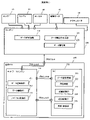
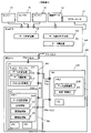
- FIG. 3 is a configuration diagram of an in-vehicle system including an integrated ECU 200 (vehicle control device) according to a first embodiment of the present invention.
- the in-vehicle system mainly includes a Zone ECU 100 and an integrated ECU 200.
- the Zone ECU 100 is connected to the sensor 1 (10), the sensor 2 (20), and the sensor 3 (30) via a communication line.
- the sensor data from each sensor is input to the Zone ECU 100.
- the sensor 1 (10), the sensor 2 (20), and the sensor 3 (30) are various sensors that sense arbitrary information, but in this embodiment, at least one of them is a camera.
- Control data 40 is input to the Zone ECU 100 via a communication line.
- the control data 40 is output from, for example, a sensor that senses information (steering amount, etc.) used as an input for controlling the chassis system or the power train system.
- the Zone ECU 100 is connected to the actuator 50 via a control line.
- the actuator 50 is controlled by a control signal indicating a target control amount.
- the actuator 50 is controlled so that, for example, the control data 40 and the target control amount match.
- the Zone ECU 100 includes a data transmission / reception unit 101, a data identifier assigning unit 102, and a data aggregation unit 103.
- the data transmission / reception unit 101 transmits / receives data.
- the data aggregation unit 103 aggregates the sensor data of the sensor 1 (10), the sensor 2 (20), the sensor 3 (30), and the control data 40.
- the data identifier assigning unit 102 assigns an identifier to the aggregated data.
- the data transmission / reception unit 101 transmits the aggregated data to which the identifier is given to the integrated ECU 200.
- the integrated ECU 200 includes a network engine 210 composed of an FPGA (Field Programmable Gate Array) and an SoC 220 composed of an integrated circuit.
- the network engine 210 is connected to the Zone ECU 100 via the communication line of Protocol A. Further, the network engine 210 is connected to the SoC 220 via a communication line between protocol B and protocol C.
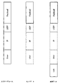
- protocol A is Ethernet (FIG. 14A)
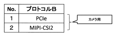
- protocol B is PCIe, MIPI-CSI2, etc. for camera data
- protocol C is CAN, SPI, etc. for control data (FIG. 14B).
- FIG. 14C FIG. 14C).
- the network engine 210 includes a data transmission / reception unit 211, a data identification unit 212, and a protocol conversion unit 213.
- the data transmission / reception unit 211 transmits / receives data.
- the data identification unit 212 identifies the protocol of the communication interface of the SoC 220 which is the destination of the data received from the Zone ECU 100.
- the protocol conversion unit 213 converts the data received from the Zone ECU 100 into the protocol data of the communication interface of the destination SoC 220.
- the data transmission / reception unit 211 transmits the converted data to the SoC 220 via the communication interface (communication device, communication line, port, etc.) of the destination SoC 220.
- the SoC 220 includes a data transmission / reception unit 221, a preprocessing unit 222, a recognition processing unit 223, a recognition processing unit 224, and a judgment / control unit 225.
- the data transmission / reception unit 221 transmits / receives data.
- the preprocessing unit 222 as predetermined preprocessing, for example, via the camera data received via the communication line of protocol B (PCIe, MIPI-CSI2, etc.) or the communication line of protocol C (CAN, SPI, etc.). Removes noise from received control data.
- the recognition processing unit 223 detects an object such as a sign from the camera data.
- the cognitive processing unit 224 recognizes information such as a speed limit implied by the detected sign or the like (object).
- the judgment / control unit 225 controls the vehicle so that the speed of the vehicle is within the recognized speed limit, for example. That is, the judgment / control unit 225 contains the control data (input data for control) received via the communication line of protocol C (CAN, SPI, etc.) and the information such as the speed limit recognized by the cognitive processing unit 224. Calculate the target control amount of the actuator from.
- the data transmission / reception unit 221 transmits a control signal indicating a target control amount to the network engine 210 via a communication line of protocol C (CAN, SPI, etc.). The control signal is transmitted to the actuator 50 via the network engine 210 and the Zone ECU 100.
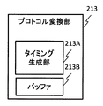
- FIG. 4 is a configuration diagram of the protocol conversion unit 213 shown in FIG.
- the protocol conversion unit 213 includes a timing generation unit 213A and a buffer 213B.
- the timing generation unit 213A generates timing for transferring camera data to the SoC 220 via a communication line of protocol B (PCIe, MIPI-CSI2, etc.) at a predetermined cycle (for example, 40 ms) according to the frame rate of the camera. (Notice. However, when the control data is received, the timing generation unit 213A generates (notifies) the timing for transferring the control data via the communication line of the protocol C (CAN, SPI, etc.) with the highest priority.
- the buffer 213B performs buffering in order to transfer camera data at a predetermined cycle.
- the timing generation unit 213A of the network engine 210 transmits the vehicle control information (control data) to the integrated circuit (SoC 220 or SoC 230) with priority over the outside world recognition information (camera data) and the outside world recognition information (SoC).
- the timing to periodically transmit the camera data) to the integrated circuit is generated.
- the buffer 213B of the network engine 210 buffers the outside world recognition information (camera data). This makes it possible to control the amount of communication from the network engine 210 to the integrated circuit (SoC 220 or SoC 230).
- the software processing can be reduced and the CPU load can be reduced by changing the information to the protocol corresponding to the dedicated interface mounted on the SoC and transmitting it.
- important control data can be processed by the CPU with low delay.
- the frame rate (fps) can be guaranteed by transferring sensor data such as camera data at regular intervals. As a result, the frame rate of the sensor data can be guaranteed.
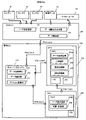
- FIG. 5 is a configuration diagram of an in-vehicle system including an integrated ECU (vehicle control unit) according to a modified example of the first embodiment.
- the integrated ECU may have a built-in Switch adapted to Protocol A (Ethernet).
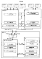
- FIG. 6 is a configuration diagram of an in-vehicle system including an integrated ECU 200 (vehicle control device) according to a second embodiment of the present invention.
- the SoC 220 of this embodiment includes hardware resources (memory, CPU) for each communication interface.
- the CPU1 / GPU of the SoC220 processes the camera data received via the communication line of protocol B (PCIe, MIPI-CSI2, etc.).
- the camera data (camera image) is input to the Vision processing chip or accelerator.
- the CPU1 / GPU functions as a data transmission / reception unit 221A, a preprocessing unit 222A, a recognition processing unit 223, and a recognition processing unit 224 by cooperating with a memory for camera data.
- CPU2 of SoC220 processes control data received via the communication line of protocol C (CAN, SPI, etc.) and performs integrated control of powertrain system, chassis system, body system, etc.
- the CPU 2 functions as a data transmission / reception unit 221B, a preprocessing unit 222B, and a judgment / control unit 225 by cooperating with a memory for control data.
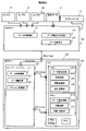
- FIG. 7 is a configuration diagram of an in-vehicle system including an integrated ECU 200 (vehicle control device) according to a third embodiment of the present invention.
- the preprocessing unit 222 is provided not in the SoC 220 but in the network engine 210.
- the processing load on the SoC 220 side can be reduced.
- FIG. 8 is a configuration diagram of an in-vehicle system including an integrated ECU 200 (vehicle control device) according to a fourth embodiment of the present invention.
- the integrated ECU 200 includes a SiP (System in Package).
- SiP includes a network engine 210 composed of FPGA and SoC 230 for camera data.
- the CPU or GPU of the SoC 230 performs image processing, AI processing, etc. on the camera data.
- the CPU or GPU of the SoC 230 functions as a data transmission / reception unit 221A, a preprocessing unit 222, a recognition processing unit 223, and a recognition processing unit 224 by cooperating with the memory of the SoC 230.
- FIG. 9 is a configuration diagram of an in-vehicle system including an integrated ECU 200 (vehicle control device) according to a fifth embodiment of the present invention.
- the integrated ECU 200 includes SoC 220 and SoC 230 that are different for each communication interface of the output destination of the network engine 210.
- FIG. 10 is a configuration diagram of an in-vehicle system including an integrated ECU (vehicle control unit) according to a sixth embodiment of the present invention.
- the integrated ECU of this embodiment includes two processing systems including a network engine and an SoC.
- FIG. 11 is an explanatory diagram of data used in an in-vehicle system including an integrated ECU (vehicle control unit) according to a seventh embodiment of the present invention.
- the configuration of the in-vehicle system may be any of the configurations of Examples 1 to 6.
- the Zone ECU 100 aggregates a plurality of pieces of information and transmits the aggregated information as one packet to the network engine 210 of the integrated ECU 200.
- the data aggregation unit 103 of the Zone ECU 100 rearranges the information (data) in the order of priority.
- the priority is higher in the order (descending order) of control data, sensor information, and entertainment information (hereinafter, entertainment information). That is, the priority of the control data is the highest, and the priority of the entertainment information is the lowest.
- the information contained in the data (packet) may be arranged in the order of priority, and the order of priority may be in descending order or ascending order. Further, the priority may be higher in the order (descending order) of chassis information, powertrain information, automatic driving information, body information, and infotainment information.
- the data transmission / reception unit 211 of the network engine 210 receives a packet from the Zone ECU 100. Each piece of information contained in the received packet is stored in the memory area of the network engine 210 according to the priority.
- the data transmission / reception unit 211 of the network engine 210 transmits the information (data) stored in the memory area to the SoC 220 or SoC 230 according to the timing generated by the timing generation unit 213A.
- the network engine 210 transmits information (control data, camera data, etc.) to the integrated circuit (SoC 220 or SoC 230) in descending order of priority.
- the information aggregated by the zone architecture can be transmitted to the integrated circuit (SoC 220 or SoC 230) according to the priority.
- the Zone ECU 100 transmits a plurality of aggregated information as one packet, but it may be transmitted as a plurality of packets in descending order of priority.
- the source address of each information is added to the packet.
- FIG. 12A is an explanatory diagram of data received from the Zone ECU 100 by the network engine 210 of the integrated ECU 200.
- the data received by the network engine 210 is composed of a header (Ether, IP, UDP) corresponding to protocol A (Ethernet), Payload, which is the actual data, and the like.
- the IP header includes a destination address, a source address, and the like.
- the network engine 210 uses the source address of the IP header for data identification, but the source address included in the Ethernet header may be used.
- FIG. 12B is an explanatory diagram of table 214 used by the network engine 210 for data identification or sorting.
- Table 214 stores the source address and the output protocol indicating the protocol of the communication interface of the destination SoC 220 in association with each other.
- the data identification unit 212 of the network engine 210 reads out the output protocol corresponding to the source address of the IP header from the table 214.
- the output protocol corresponding to the source address (source IP) of 192.168.0.1 is PCIe, and the received data is identified (determined) as camera data.
- the output protocol is associated with the data type, but the source address (source IP) may be associated with the data type.
- the IP address is used as the source address, but the MAC address and the VLAN (Virtual Local Area Network) address may be used. Further, the source address may be incorporated in the Payload.
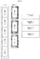
- FIG. 13 is an explanatory diagram of data (input data frame) input to the network engine 210 and data (output frame) output from the network engine 210.
- the output frame is the input data frame from which the headers (Ether, IP, UDP) have been removed. If the data input to the network engine 210 is control data, the output frame is obtained by removing the header (Ether, IP, UDP) from the input data frame and adding the output protocol header (CAN, SPI, etc.). Become. However, the Ether header, IP header, and UDP header of the control data output frame may be added after the Payload.
- FIG. 15 is a flowchart showing the processing of the network engine 210.
- the network engine 210 When the network engine 210 receives data from the Zone ECU 100 (S10: YES), the network engine 210 identifies the received data (S15).
- the network engine 210 receives data (packets) including a plurality of sets of information (control data, camera data, etc.) and their source addresses according to the first communication protocol (protocol A).
- the network engine 210 identifies the communication protocol (protocols B, C) of the communication interface of the destination integrated circuit (SoC 220 or SoC 230) corresponding to the source address of each information.
- each information is obtained from the communication protocol (protocol B, C) of the communication interface of the destination integrated circuit (SoC 220 or SoC 230) corresponding to the source address of each information (control data, camera data, etc.). It identifies whether it is the vehicle control information (control data) indicating the information used for the control of the vehicle or the outside world recognition information (camera data) indicating the information recognized about the outside world of the vehicle. This makes it possible to identify the type of information aggregated in the zone architecture.
- the network engine 210 When the identified data is camera data (S20: YES), the network engine 210 writes the camera data to the buffer 213B (S25).
- the condition of YES in S20 is not limited to the identified data being camera data (outside world recognition information), and may be sensor data other than control data.
- the network engine 210 transmits the camera data stored in the buffer 213B to the SoC 220 every predetermined cycle (for example, 40 ms) according to the frame rate of the camera (S30: YES) (S35).
- the network engine 210 transmits the control data to the SoC 220 (S35).
- the network engine 210 sorts information (control data, camera data, etc.) for each identified communication protocol (protocols B and C), and converts the sorted information into the data of the identified communication protocol. , Each converted data is transmitted to the destination integrated circuit via the communication interface (protocols B and C) of the destination integrated circuit (SoC 220 or SoC 230). As a result, the information aggregated by the zone architecture can be sorted, and the sorted information can be transmitted to the destination integrated circuit (SoC 220 or SoC 230).
- the network engine 210 transmits vehicle control information (control data) to the integrated circuit (SoC 220 or SoC 230) with priority over external recognition information (camera data). This makes it possible to control the vehicle with low delay.
- the communication protocols (protocols B and C) of the communication interface of the destination integrated circuit (SoC 220 or SoC 230) corresponding to the source address of each information (control data, camera data, etc.) are the first communication protocol (protocol A). different.
- the communication speed of the first communication protocol (protocol A) is the communication of the communication protocol (protocol B, C) of the communication interface of the destination integrated circuit (SoC 220 or SoC 230) corresponding to the source address of each information. Faster than speed.
- the information aggregated by the zone architecture can be transmitted from the Zone ECU 100 to the integrated ECU 200 at high speed.
- the embodiment of the present invention may have the following aspects.
- the first communication method is the first information including the vehicle control information (control data 40) transmitted by the first device (Zone ECU 100) and the outside world recognition information (camera data, point group data, etc.) of the own vehicle. ), The first information is separated for each information to be transmitted to different domains (destination of different protocols), and the separated information is transmitted to a client (SoC 220) for arithmetic processing (network).
- the second device includes an engine 210), selects a transmission method (protocol) to the client according to the information, and converts the transmission protocol of the information according to the selected transmission method.
- a vehicle control device comprising a unit (213).
- the protocol conversion unit (213) converts a protocol into a communication method (protocol B, C) different from the first communication method (protocol A). Characterized vehicle control device.
- the first information is the vehicle control information (control data 40) or the outside world recognition information (camera data).
- a vehicle control device having a data source identification unit (data identification unit 212) for identifying the presence or absence.
- the vehicle control device in which the second device (network engine 210) gives priority to the vehicle control information (control data 40) over the outside world recognition information (camera data) to the client (the client (network engine 210).
- a vehicle control device uses the outside world recognition information (camera data) among the first information received from the first device (Zone ECU 100).
- a vehicle control device including a buffering unit (buffer 213B) for periodically transmitting data to the client (SoC 220) and a timing generation unit (213A) for generating transfer timing to the client.
- the present invention is not limited to the above-described embodiment, but includes various modifications.
- the above-mentioned examples have been described in detail in order to explain the present invention in an easy-to-understand manner, and are not necessarily limited to those having all the described configurations.
- it is possible to replace a part of the configuration of one embodiment with the configuration of another embodiment and it is also possible to add the configuration of another embodiment to the configuration of one embodiment.
- each of the above configurations, functions, etc. may be realized by hardware, for example, by designing a part or all of them with an integrated circuit. Further, each of the above configurations, functions, and the like may be realized by software by the processor interpreting and executing a program that realizes each function. Information such as programs, tables, and files that realize each function can be placed in a memory, a recording device such as a hard disk or SSD (Solid State Drive), or a recording medium such as an IC card, SD card, or DVD.
- a recording device such as a hard disk or SSD (Solid State Drive)
- a recording medium such as an IC card, SD card, or DVD.
Landscapes
- Physics & Mathematics (AREA)
- General Physics & Mathematics (AREA)
- Engineering & Computer Science (AREA)
- Computer Networks & Wireless Communication (AREA)
- Signal Processing (AREA)
- Small-Scale Networks (AREA)
Abstract
Description
はじめに、本発明との比較例1として、ゲートウェイの機能の概要を説明する。図1は、ゲートウェイの機能を示すブロック図である。
次に、本発明との比較例2として、ゾーンアーキテクチャのシステム構成の概要を説明する。図2は、ゾーンアーキテクチャのシステム構成を示すブロック図である。
図3は、本発明の実施例1による統合ECU200(車両制御装置)を含む車載システムの構成図である。車載システムは、主として、Zone ECU100と統合ECU200を備える。
図5は、実施例1の変形例による統合ECU(車両制御装置)を含む車載システムの構成図である。図5に示すように、複数のZone ECUからネットワークエンジンへデータを入力するため、統合ECUはプロトコルA(Ethernet)に適応したSwitchを内蔵してもよい。
図6は、本発明の実施例2による統合ECU200(車両制御装置)を含む車載システムの構成図である。本実施例のSoC220は、通信インターフェースごとにハードウェア資源(メモリ、CPU)を備える。
図7は、本発明の実施例3による統合ECU200(車両制御装置)を含む車載システムの構成図である。本実施例では、前処理部222は、SoC220ではなく、ネットワークエンジン210に設けられる。
図8は、本発明の実施例4による統合ECU200(車両制御装置)を含む車載システムの構成図である。本実施例では、統合ECU200はSiP(System in Package)を備える。
図9は、本発明の実施例5による統合ECU200(車両制御装置)を含む車載システムの構成図である。本実施例では、統合ECU200は、ネットワークエンジン210の出力先の通信インターフェースごとに異なるSoC220、SoC230を備える。
図10は、本発明の実施例6による統合ECU(車両制御装置)を含む車載システムの構成図である。本実施例の統合ECUは、ネットワークエンジンとSoCから構成される2系統の処理系を備える。
図11は、本発明の実施例7による統合ECU(車両制御装置)を含む車載システムに用いられるデータの説明図である。なお、車載システムの構成は実施例1~6のいずれの構成であってもよい。本実施例では、Zone ECU100は、複数の情報を集約し、集約された情報を1パケットとして統合ECU200のネットワークエンジン210に送信する。
図12Aは、統合ECU200のネットワークエンジン210がZone ECU100から受信するデータの説明図である。
図13は、ネットワークエンジン210に入力されるデータ(入力データフレーム)とネットワークエンジン210から出力されるデータ(出力フレーム)の説明図である。
図15は、ネットワークエンジン210の処理を示すフローチャートである。
Claims (7)
- 情報を処理する少なくとも1つの集積回路と、
前記情報とその送信元アドレスの組を複数含むデータを第1通信プロトコルに従って受信し、それぞれの前記情報の送信元アドレスに対応する宛先の前記集積回路の通信インターフェースの通信プロトコルを識別し、識別された通信プロトコルごとに前記情報を仕分けし、仕分けられた前記情報を識別された通信プロトコルのデータに変換し、変換されたそれぞれのデータを宛先の前記集積回路の前記通信インターフェースを介して宛先の前記集積回路へ送信するネットワークエンジンと、
を備えることを特徴とする車両制御装置。 - 請求項1に記載の車両制御装置であって、
それぞれの前記情報の送信元アドレスに対応する宛先の前記集積回路の通信インターフェースの通信プロトコルは、前記第1通信プロトコルと異なる
ことを特徴とする車両制御装置。 - 請求項2に記載の車両制御装置であって、
前記第1通信プロトコルの通信速度は、
それぞれの前記情報の送信元アドレスに対応する宛先の前記集積回路の通信インターフェースの通信プロトコルの通信速度よりも高速である
ことを特徴とする車両制御装置。 - 請求項1に記載の車両制御装置であって、
前記ネットワークエンジンは、
それぞれの前記情報の送信元アドレスに対応する宛先の前記集積回路の通信インターフェースの通信プロトコルからそれぞれの前記情報が車両の制御に用いる情報を示す車両制御情報であるか前記車両の外界について認識された情報を示す外界認識情報かを識別する
ことを特徴とする車両制御装置。 - 請求項4に記載の車両制御装置であって、
前記ネットワークエンジンは、
前記車両制御情報を前記外界認識情報よりも優先的に前記集積回路へ送信する
ことを特徴とする車両制御装置。 - 請求項5に記載の車両制御装置であって、
前記ネットワークエンジンは、
前記車両制御情報を前記外界認識情報よりも優先的に前記集積回路へ送信するタイミングと前記外界認識情報を周期的に前記集積回路へ送信するタイミングとを生成するタイミング生成部と、
前記外界認識情報をバッファリングするバッファと、を備える
ことを特徴とする車両制御装置。 - 請求項1に記載の車両制御装置であって、
前記データに含まれる前記情報は、
優先度の順に並べられ、
前記ネットワークエンジンは、
優先度の高い順に前記情報を前記集積回路へ送信する
ことを特徴とする車両制御装置。
Priority Applications (3)
| Application Number | Priority Date | Filing Date | Title |
|---|---|---|---|
| DE112021003733.1T DE112021003733T5 (de) | 2020-09-30 | 2021-06-14 | Fahrzeugsteuervorrichtung |
| US18/041,701 US12374169B2 (en) | 2020-09-30 | 2021-06-14 | Vehicle control device |
| JP2022553467A JP7469498B2 (ja) | 2020-09-30 | 2021-06-14 | 車両制御装置 |
Applications Claiming Priority (2)
| Application Number | Priority Date | Filing Date | Title |
|---|---|---|---|
| JP2020166384 | 2020-09-30 | ||
| JP2020-166384 | 2020-09-30 |
Publications (1)
| Publication Number | Publication Date |
|---|---|
| WO2022070525A1 true WO2022070525A1 (ja) | 2022-04-07 |
Family
ID=80949829
Family Applications (1)
| Application Number | Title | Priority Date | Filing Date |
|---|---|---|---|
| PCT/JP2021/022568 Ceased WO2022070525A1 (ja) | 2020-09-30 | 2021-06-14 | 車両制御装置 |
Country Status (4)
| Country | Link |
|---|---|
| US (1) | US12374169B2 (ja) |
| JP (1) | JP7469498B2 (ja) |
| DE (1) | DE112021003733T5 (ja) |
| WO (1) | WO2022070525A1 (ja) |
Cited By (1)
| Publication number | Priority date | Publication date | Assignee | Title |
|---|---|---|---|---|
| JP2026511226A (ja) * | 2023-03-27 | 2026-04-10 | メルセデス・ベンツ グループ アクチェンゲゼルシャフト | 車両接続視認性のための方法及びコンピューティングシステム |
Families Citing this family (8)
| Publication number | Priority date | Publication date | Assignee | Title |
|---|---|---|---|---|
| US11538287B2 (en) | 2019-09-20 | 2022-12-27 | Sonatus, Inc. | System, method, and apparatus for managing vehicle data collection |
| JP7682863B2 (ja) | 2019-09-20 | 2025-05-26 | ソナタス インコーポレイテッド | 車両上の混合ネットワーク通信をサポートするためのシステム、方法、及び装置 |
| US12261747B2 (en) * | 2019-09-20 | 2025-03-25 | Sonatus, Inc. | System, method, and apparatus to execute vehicle communications using a zonal architecture |
| US12211323B2 (en) | 2020-03-06 | 2025-01-28 | Sonatus, Inc. | System, method, and apparatus for managing vehicle automation |
| US12403921B2 (en) | 2020-03-06 | 2025-09-02 | Sonatus, Inc. | System, method, and apparatus for managing vehicle automation |
| US12528442B2 (en) | 2020-03-06 | 2026-01-20 | Sonatus, Inc. | System, method, and apparatus for managing vehicle data collection |
| US12573245B2 (en) | 2020-03-06 | 2026-03-10 | Sonatus, Inc. | System, method, and apparatus for managing vehicle automation |
| JP7729123B2 (ja) * | 2021-09-02 | 2025-08-26 | 株式会社デンソー | 車両用制御システム、および回路装置 |
Citations (3)
| Publication number | Priority date | Publication date | Assignee | Title |
|---|---|---|---|---|
| JP2013179539A (ja) * | 2012-02-29 | 2013-09-09 | Denso Corp | ゲートウエイ装置 |
| US20190394089A1 (en) * | 2018-06-22 | 2019-12-26 | Blackberry Limited | Configuring a firewall system in a vehicle network |
| JP2020037387A (ja) * | 2018-06-29 | 2020-03-12 | アプティブ・テクノロジーズ・リミテッド | 自動車アプリケーションのための電力およびデータセンタ(PDC:power and data center) |
Family Cites Families (4)
| Publication number | Priority date | Publication date | Assignee | Title |
|---|---|---|---|---|
| US7412588B2 (en) * | 2003-07-25 | 2008-08-12 | International Business Machines Corporation | Network processor system on chip with bridge coupling protocol converting multiprocessor macro core local bus to peripheral interfaces coupled system bus |
| US20190028294A1 (en) * | 2016-01-11 | 2019-01-24 | Carrier Corporation | Improvements in communication systems for remote device control |
| JP6962697B2 (ja) * | 2016-05-27 | 2021-11-05 | パナソニック インテレクチュアル プロパティ コーポレーション オブ アメリカPanasonic Intellectual Property Corporation of America | ネットワークハブ、転送方法及び車載ネットワークシステム |
| JP6768614B2 (ja) * | 2017-09-15 | 2020-10-14 | 矢崎総業株式会社 | 車載ネットワーク装置 |
-
2021
- 2021-06-14 JP JP2022553467A patent/JP7469498B2/ja active Active
- 2021-06-14 US US18/041,701 patent/US12374169B2/en active Active
- 2021-06-14 WO PCT/JP2021/022568 patent/WO2022070525A1/ja not_active Ceased
- 2021-06-14 DE DE112021003733.1T patent/DE112021003733T5/de active Pending
Patent Citations (3)
| Publication number | Priority date | Publication date | Assignee | Title |
|---|---|---|---|---|
| JP2013179539A (ja) * | 2012-02-29 | 2013-09-09 | Denso Corp | ゲートウエイ装置 |
| US20190394089A1 (en) * | 2018-06-22 | 2019-12-26 | Blackberry Limited | Configuring a firewall system in a vehicle network |
| JP2020037387A (ja) * | 2018-06-29 | 2020-03-12 | アプティブ・テクノロジーズ・リミテッド | 自動車アプリケーションのための電力およびデータセンタ(PDC:power and data center) |
Cited By (2)
| Publication number | Priority date | Publication date | Assignee | Title |
|---|---|---|---|---|
| JP2026511226A (ja) * | 2023-03-27 | 2026-04-10 | メルセデス・ベンツ グループ アクチェンゲゼルシャフト | 車両接続視認性のための方法及びコンピューティングシステム |
| JP7900620B2 (ja) | 2023-03-27 | 2026-08-04 | メルセデス・ベンツ グループ アクチェンゲゼルシャフト | 車両接続視認性のための方法及びコンピューティングシステム |
Also Published As
| Publication number | Publication date |
|---|---|
| US12374169B2 (en) | 2025-07-29 |
| JP7469498B2 (ja) | 2024-04-16 |
| DE112021003733T5 (de) | 2023-06-22 |
| JPWO2022070525A1 (ja) | 2022-04-07 |
| US20230306796A1 (en) | 2023-09-28 |
Similar Documents
| Publication | Publication Date | Title |
|---|---|---|
| JP7469498B2 (ja) | 車両制御装置 | |
| JP7289332B2 (ja) | 電子制御ユニット、フレーム生成方法及びプログラム | |
| US10848442B2 (en) | Heterogeneous packet-based transport | |
| CN103685000B (zh) | 网关模块、通信系统和在用户之间传输数据的方法 | |
| US7480312B2 (en) | Network traffic accelerator system and method | |
| EP3468108B1 (en) | Network hub, transfer method, and on-vehicle network system | |
| CN100448221C (zh) | 在计算机服务器中共享以太网适配器的方法和装置 | |
| US8571033B2 (en) | Smart routing between peers in a point-to-point link based system | |
| US20130145072A1 (en) | High availability and I/O aggregation for server environments | |
| CN113395197B (zh) | 网关装置、车载网络系统、转送方法和计算机可读记录介质 | |
| EP3461086B1 (en) | Communication apparatus, communication method and computer-readable medium | |
| EP3079316B1 (en) | Network switch circuit, system and method | |
| EP4092970A1 (en) | Monitoring controller area network (can) xl nodes | |
| CN108605007A (zh) | 中继装置 | |
| US11128569B2 (en) | Load distribution system and load distribution method | |
| JP2026083099A (ja) | 管理装置、車載システム、通信管理方法および通信管理プログラム | |
| US11902048B2 (en) | Control unit architecture for vehicles | |
| CN113347017A (zh) | 一种网络通信的方法、装置、网络节点设备及混合网络 | |
| CN118871887A (zh) | 用于在车辆的通信系统中转发数据的方法 | |
| JP5728043B2 (ja) | ゲートウェイ装置 | |
| JP7640491B2 (ja) | ストレージ装置及びそのプロトコル変換方法 | |
| JP7431848B2 (ja) | 車両制御装置及びデータ転送制御方法 | |
| CN108123990B (zh) | 一种数据存储方法、数据存储系统及数据处理设备 | |
| Geier et al. | Hardware-accelerated data acquisition and authentication for high-speed video streams on future heterogeneous automotive processing platforms | |
| CN119605129A (zh) | 中继装置、通信控制方法以及通信控制程序 |
Legal Events
| Date | Code | Title | Description |
|---|---|---|---|
| 121 | Ep: the epo has been informed by wipo that ep was designated in this application |
Ref document number: 21874829 Country of ref document: EP Kind code of ref document: A1 |
|
| ENP | Entry into the national phase |
Ref document number: 2022553467 Country of ref document: JP Kind code of ref document: A |
|
| 122 | Ep: pct application non-entry in european phase |
Ref document number: 21874829 Country of ref document: EP Kind code of ref document: A1 |
|
| WWG | Wipo information: grant in national office |
Ref document number: 18041701 Country of ref document: US |