WO2022065460A1 - 生物体の操作方法および操作装置 - Google Patents
生物体の操作方法および操作装置 Download PDFInfo
- Publication number
- WO2022065460A1 WO2022065460A1 PCT/JP2021/035209 JP2021035209W WO2022065460A1 WO 2022065460 A1 WO2022065460 A1 WO 2022065460A1 JP 2021035209 W JP2021035209 W JP 2021035209W WO 2022065460 A1 WO2022065460 A1 WO 2022065460A1
- Authority
- WO
- WIPO (PCT)
- Prior art keywords
- flow path
- gas
- nozzle
- liquid
- liquid interface
- Prior art date
- Legal status (The legal status is an assumption and is not a legal conclusion. Google has not performed a legal analysis and makes no representation as to the accuracy of the status listed.)
- Ceased
Links
Images


Classifications
-
- C—CHEMISTRY; METALLURGY
- C12—BIOCHEMISTRY; BEER; SPIRITS; WINE; VINEGAR; MICROBIOLOGY; ENZYMOLOGY; MUTATION OR GENETIC ENGINEERING
- C12N—MICROORGANISMS OR ENZYMES; COMPOSITIONS THEREOF; PROPAGATING, PRESERVING, OR MAINTAINING MICROORGANISMS; MUTATION OR GENETIC ENGINEERING; CULTURE MEDIA
- C12N1/00—Microorganisms; Compositions thereof; Processes of propagating, maintaining or preserving microorganisms or compositions thereof; Processes of preparing or isolating a composition containing a microorganism; Culture media therefor
- C12N1/02—Separating microorganisms from their culture media
-
- C—CHEMISTRY; METALLURGY
- C12—BIOCHEMISTRY; BEER; SPIRITS; WINE; VINEGAR; MICROBIOLOGY; ENZYMOLOGY; MUTATION OR GENETIC ENGINEERING
- C12M—APPARATUS FOR ENZYMOLOGY OR MICROBIOLOGY; APPARATUS FOR CULTURING MICROORGANISMS FOR PRODUCING BIOMASS, FOR GROWING CELLS OR FOR OBTAINING FERMENTATION OR METABOLIC PRODUCTS, i.e. BIOREACTORS OR FERMENTERS
- C12M27/00—Means for mixing, agitating or circulating fluids in the vessel
- C12M27/18—Flow directing inserts
-
- B—PERFORMING OPERATIONS; TRANSPORTING
- B01—PHYSICAL OR CHEMICAL PROCESSES OR APPARATUS IN GENERAL
- B01L—CHEMICAL OR PHYSICAL LABORATORY APPARATUS FOR GENERAL USE
- B01L3/00—Containers or dishes for laboratory use, e.g. laboratory glassware; Droppers
- B01L3/50—Containers for the purpose of retaining a material to be analysed, e.g. test tubes
- B01L3/502—Containers for the purpose of retaining a material to be analysed, e.g. test tubes with fluid transport, e.g. in multi-compartment structures
- B01L3/5027—Containers for the purpose of retaining a material to be analysed, e.g. test tubes with fluid transport, e.g. in multi-compartment structures by integrated microfluidic structures, i.e. dimensions of channels and chambers are such that surface tension forces are important, e.g. lab-on-a-chip
- B01L3/502761—Containers for the purpose of retaining a material to be analysed, e.g. test tubes with fluid transport, e.g. in multi-compartment structures by integrated microfluidic structures, i.e. dimensions of channels and chambers are such that surface tension forces are important, e.g. lab-on-a-chip specially adapted for handling suspended solids or molecules independently from the bulk fluid flow, e.g. for trapping or sorting beads or physically stretching molecules
-
- B—PERFORMING OPERATIONS; TRANSPORTING
- B01—PHYSICAL OR CHEMICAL PROCESSES OR APPARATUS IN GENERAL
- B01L—CHEMICAL OR PHYSICAL LABORATORY APPARATUS FOR GENERAL USE
- B01L3/00—Containers or dishes for laboratory use, e.g. laboratory glassware; Droppers
- B01L3/50—Containers for the purpose of retaining a material to be analysed, e.g. test tubes
- B01L3/502—Containers for the purpose of retaining a material to be analysed, e.g. test tubes with fluid transport, e.g. in multi-compartment structures
- B01L3/5027—Containers for the purpose of retaining a material to be analysed, e.g. test tubes with fluid transport, e.g. in multi-compartment structures by integrated microfluidic structures, i.e. dimensions of channels and chambers are such that surface tension forces are important, e.g. lab-on-a-chip
- B01L3/502769—Containers for the purpose of retaining a material to be analysed, e.g. test tubes with fluid transport, e.g. in multi-compartment structures by integrated microfluidic structures, i.e. dimensions of channels and chambers are such that surface tension forces are important, e.g. lab-on-a-chip characterised by multiphase flow arrangements
-
- C—CHEMISTRY; METALLURGY
- C12—BIOCHEMISTRY; BEER; SPIRITS; WINE; VINEGAR; MICROBIOLOGY; ENZYMOLOGY; MUTATION OR GENETIC ENGINEERING
- C12M—APPARATUS FOR ENZYMOLOGY OR MICROBIOLOGY; APPARATUS FOR CULTURING MICROORGANISMS FOR PRODUCING BIOMASS, FOR GROWING CELLS OR FOR OBTAINING FERMENTATION OR METABOLIC PRODUCTS, i.e. BIOREACTORS OR FERMENTERS
- C12M23/00—Constructional details, e.g. recesses, hinges
- C12M23/40—Manifolds; Distribution pieces
-
- C—CHEMISTRY; METALLURGY
- C12—BIOCHEMISTRY; BEER; SPIRITS; WINE; VINEGAR; MICROBIOLOGY; ENZYMOLOGY; MUTATION OR GENETIC ENGINEERING
- C12M—APPARATUS FOR ENZYMOLOGY OR MICROBIOLOGY; APPARATUS FOR CULTURING MICROORGANISMS FOR PRODUCING BIOMASS, FOR GROWING CELLS OR FOR OBTAINING FERMENTATION OR METABOLIC PRODUCTS, i.e. BIOREACTORS OR FERMENTERS
- C12M35/00—Means for application of stress for stimulating the growth of microorganisms or the generation of fermentation or metabolic products; Means for electroporation or cell fusion
-
- B—PERFORMING OPERATIONS; TRANSPORTING
- B01—PHYSICAL OR CHEMICAL PROCESSES OR APPARATUS IN GENERAL
- B01L—CHEMICAL OR PHYSICAL LABORATORY APPARATUS FOR GENERAL USE
- B01L2200/00—Solutions for specific problems relating to chemical or physical laboratory apparatus
- B01L2200/06—Fluid handling related problems
- B01L2200/0647—Handling flowable solids, e.g. microscopic beads, cells, particles
- B01L2200/0668—Trapping microscopic beads
-
- B—PERFORMING OPERATIONS; TRANSPORTING
- B01—PHYSICAL OR CHEMICAL PROCESSES OR APPARATUS IN GENERAL
- B01L—CHEMICAL OR PHYSICAL LABORATORY APPARATUS FOR GENERAL USE
- B01L2300/00—Additional constructional details
- B01L2300/08—Geometry, shape and general structure
- B01L2300/0832—Geometry, shape and general structure cylindrical, tube shaped
- B01L2300/0838—Capillaries
Definitions
- the present invention relates to a method for manipulating an organism and a device for manipulating the organism.
- Patent Document 1 discloses a cell suction support system that sucks a target cell using a chip.
- Patent Document 1 Japanese Unexamined Patent Publication No. 2016-00000
- a method for manipulating an organism is provided.
- the method for manipulating an organism is to immerse the end of the flow path in the liquid in which the organism is immersed, and form a gas-liquid interface in or at the end of the flow path that exerts a restoring force against minute interface movement. It may be provided with a gas-liquid interface forming step.
- the method of manipulating the organism may include an operation step of manipulating the organism using the gas-liquid interface.
- the gas-liquid interface forming step of the method of manipulating the organism may include a step of releasing or sucking gas from the end portion.
- the gas-liquid interface formation step of the method of manipulating the organism releases gas from the end portion, and a restoring force acts on the end portion against a minute volume change. It may include maintaining the gas-liquid interface.
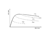
- the gas volume V (m3) occupied by the gas continuous from the gas-liquid interface to the inside of the flow path in the gas-liquid interface formation step of the method of operating the organism is determined.
- the following equation may be satisfied with respect to the radius rh (m) at the end of the flow path.
- the method of manipulating the organism is a volume reduction that reduces the gas volume occupied by the gas continuous from the end of the flow path to the inside prior to the gas-liquid interface formation step. Further steps may be included.
- the liquid in the volume reduction step of the method of operating the organism, the liquid is taken into the inside of the flow path, and the gas inside the flow path is partitioned by the taken-in liquid. May include doing.
- the volume reduction step of the method of manipulating the organism may include filling the flow path with a filler that blocks a portion of the space inside the flow path. ..
- the flow path of the method of operating the organism may include a space formed inside the nozzle and the pump connected to the nozzle.
- the volume reduction step may include reducing the capacity of the pump to 10% or less of its maximum capacity.
- the flow path of the method of operating the organism may be provided with a dividing member that divides the space inside the flow path.
- the cross-sectional shape of the end portion of the flow path of the method of operating the organism may be a shape having a protrusion toward the inside.
- the inner surface of the flow path and the end surface of the flow path member forming the flow path are used.
- An angle is formed, and the angle formed by the angle may be in the range of 90 ⁇ 5 degrees.
- the contact angle between the flow path member forming the flow path of the method of operating the organism and the liquid by the sessile drop technique may be 90 degrees or less.
- the flow path of the method of operating the organism may have a tip portion provided on the end side.
- the flow path may have an inner portion connected to the tip portion and having a flow path diameter different from the flow path diameter of the tip portion.
- the flow path may form a step at the connection portion between the tip portion and the inner portion.
- the flow path of the method of operating the organism may include a portion having a large flow path diameter and a portion having a small flow path diameter.
- the flow path diameter of the portion having a small flow path diameter may be 1/10 or less of the flow path diameter of the portion having a large flow path diameter.
- a surface tension reducing step of reducing the surface tension of the liquid with the gas may be further included before the gas-liquid interface forming step of the method of manipulating the organism. ..
- the method of manipulating the organism may further include a detection step of detecting the first pressure applied to the gas-liquid interface.
- the detection step detects a change in the first pressure when the gas continues to be discharged into the flow path, and determines a second pressure capable of forming the gas-liquid interface based on the changed value of the first pressure. You may decide.
- the method of manipulating the organism may further include a detection step of detecting the first pressure applied to the gas-liquid interface.
- the method of operating the organism is that the end of the flow path comes into contact with the liquid based on the change in the first pressure, or the gas-liquid interface formed at the end of the flow path causes the organism to operate. It may be detected that it has come into contact with the bottom of the container to be cultured.
- the method of manipulating the organism further includes a movement step of moving the flow path and the organism relative to each other before the gas-liquid interface formation step. May include.
- an organism manipulation device for manipulating an organism.
- the organism manipulation device may include a flow path whose ends are immersed in the liquid into which the organism is immersed.
- the organism manipulation device forms a gas-liquid interface in which a restoring force acts against a minute interface movement inside or at the end of the flow path, and the gas-liquid interface manipulation unit operates the organism by the gas-liquid interface. May be prepared.
- the gas-liquid interface operation portion of the organism manipulation device may release a gas into the liquid from the end portion.
- the gas-liquid interface may be maintained at the end, where the restoring force acts against minute volume changes.
- the gas volume V (m3) occupied by the gas continuous from the gas-liquid interface of the flow path to the inside is the radius of the end portion of the flow path.
- the following equation may be satisfied for rh (m).
- an organism manipulation device for manipulating an organism.
- the organism manipulation device may include a pump that introduces gas into the flow path to form a gas-liquid interface at the end.
- the organism manipulating device may include a pressure detecting unit that detects a first pressure applied to the gas-liquid interface.
- the organism manipulation device may include a storage unit in which a second pressure capable of maintaining the gas-liquid interface is stored.
- the pump changes the amount of the gas to be introduced based on the change in the first pressure, and controls the gas to be introduced into the flow path so that the first pressure is maintained at the second pressure or lower. good.
- An example of the apparatus configuration of the organism manipulation apparatus 100 in this embodiment is shown.
- An example of the apparatus configuration of the organism manipulation apparatus 100 in this embodiment is shown.
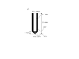
- An example of a schematic diagram showing the structure of the nozzle 49 in this embodiment is shown.
- An example of a schematic diagram showing the structure of the nozzle 49 in this embodiment is shown.
- An example of a schematic diagram showing the structure of the nozzle 49 in this embodiment is shown.
- An example of a schematic diagram showing the structure of the nozzle 49 in this embodiment is shown.
- An example of a schematic diagram showing an example of a method for recovering an organism in the present embodiment is shown.
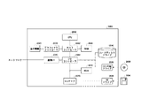
- An example of a specific configuration of the information processing apparatus 170 in this embodiment is shown.
- An example of the flow of the method of manipulating an organism in this embodiment is shown.
- An example of the GUI image displayed on the output unit 160 in this embodiment is shown.
- An example of the GUI image displayed on the output unit 160 in this embodiment is shown.
- An example of the GUI image displayed on the output unit 160 in this embodiment is shown.
- An example of the GUI image displayed on the output unit 160 in this embodiment is shown.
- An example of the GUI image displayed on the output unit 160 in this embodiment is shown.
- An example of the GUI image displayed on the output unit 160 in this embodiment is shown.
- An example of the flow for substituting or adding the liquid of S600 in this embodiment is shown.
- An example of the flow for moving the relative position between the nozzle 49 of S200 and the cell in this embodiment is shown.
- An example of the flow for moving the relative position between the nozzle 49 of S200 and the cell in this embodiment is shown.
- An example of the flow for moving the relative position between the nozzle 49 of S200 and the cell in this embodiment is shown.
- An example of the flow for forming bubbles of S300 in this embodiment is shown.
- An example of the flow for forming bubbles of S300 in this embodiment is shown.
- An example of the flow for executing the operation of S400 in this embodiment is shown.
- An example of recovering the cytoplasm and cell membrane from cells in this embodiment is shown.
- An example of the present embodiment in which cells are attached to bubbles and detached is shown.
- An example of a schematic diagram showing a method for recovering cells in this embodiment is shown.
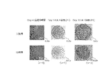
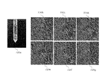
- An example of a passaged cell in this embodiment is shown.
- An example of a passaged cell in this embodiment is shown.
- An example of analyzing the recovered cells in this embodiment is shown.
- An example of a schematic diagram showing the retained cells in this embodiment is shown.
- An example of compressed cells in this embodiment is shown.
- An example of a method of reducing the volume in the flow path of the nozzle is shown.
- An example of a method of reducing the volume in the flow path of the nozzle is shown.
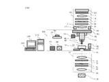
- FIG. 1A shows an example of the device configuration of the biological body operating device 100 in the present embodiment.
- the organism manipulation device 100 according to the present invention manipulates an organism such as a cell by using an interface between a gas and a liquid.
- the organism manipulation device 100 can perform various operations on the organism, such as attaching the organism to the interface and then peeling off the organism adhered to the solid phase.
- the biological body operation device 100 includes a microscope unit 50, a camera 60, a camera 70, a gas-liquid interface operation unit 101, an output unit 160, an information processing device 170, and an input unit 180.
- the microscope unit 50 is a device for magnifying and observing or displaying the operation target 35 using a microscope.
- the operation target 35 is an organism.
- the organism may be an organic organism.
- the organism may be a cell.
- the cell may be an animal cell or a plant cell.
- the cell may be a living cell or a dead cell.
- the organism may be an organism other than a cell.
- the organism may be a microorganism, a fungus, an algae, a biological tissue, a spheroid, or the like.
- the organism may also contain intracellular organelles.
- the microscope unit 50 includes a light source 1 for observing a fluorescent image, a dichroic mirror 2, a light deflector 3, a relay lens 4, a dichroic mirror 5, an objective lens 6, a condenser lens 7, and a condenser lens 8. It includes a bandpass filter 9, a light source for observing a transmission image 10, a barrier filter 11, a projection lens 12, a barrier filter 13, a projection lens 14, a pinhole 15, a light source 16, and a light source 17.
- the fluorescent image observation light source 1 is a light source used when observing the fluorescent image of the operation target 35.
- the operation target 35 may or may not be fluorescently labeled with one or more types of fluorescent substances.
- the fluorescence image observation light source 1 irradiates the operation target 35 with light to be excited or reflected.
- the transmitted image observation light source 10 is a light source used when observing the transmitted image of the operation target 35.
- the light source 10 for observing a transmitted image shines light transmitted through the operation target 35.
- the light transmitted through the operation target 35 may pass through the outside of the nozzle or the inside of the nozzle.
- the microscope unit 50 may have a known configuration.
- the structure of the microscope unit 50 may have the structure described in Japanese Patent Application Laid-Open No. 7-13083 or Japanese Patent No. 3814869.
- the camera 60 captures a fluorescent image of the operation target 35 and generates an image.
- the image data generated by the camera 60 may be recorded inside the information processing apparatus 170 (for example, the recording unit 190 described later) and / or may be output to the output unit 160.
- the camera 60 may be a camera that captures a fluorescent image, but is not limited to this. In the following description, the camera 60 is a camera that captures a fluorescent image.
- the camera 70 captures a transmitted image of the operation target 35 and generates an image.
- the image data generated by the camera 70 may be recorded inside the information processing apparatus 170 (for example, the recording unit 190 described later) and / or may be output to the output unit 160.
- the camera 70 may be a camera that captures a transmitted image, but is not limited to this. In the following description, the camera 70 is a camera that captures a transmitted image.
- the camera 60 and the camera 70 have an image pickup sensor (not shown).
- the camera 60 and the camera 70 may be cooling cameras.
- a cooling camera is a camera that can suppress noise generated by heat by cooling an image sensor.
- the image pickup sensor may be a CMOS image sensor (Complementary Metal Oxide Semiconductor) or a CCD image sensor (Charge Coupled Device).
- the camera 60 and the camera 70 may be housed in a housing different from that of the microscope unit 50.
- the gas-liquid interface operation unit 101 operates the operation target 35 using the gas-liquid interface between gas and liquid.
- the gas-liquid interface manipulation unit 101 forms bubbles in a liquid to manipulate an organism (for example, a cell) in the liquid.
- the gas-liquid interface operation unit 101 includes a nozzle actuator 40, a sample actuator 41, a flow path imaging camera 42, a light source 45, a light source 46, a pressure generation unit 47, a sensor unit 48, and a nozzle 49.
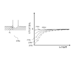
- the gas-liquid interface operation unit 101 may form a gas-liquid interface 255 inside or at the end of the flow path 51 in which a restoring force acts against a minute interface movement.
- the gas-liquid interface operation unit 101 may release a gas into the liquid from the end portion 254 of the nozzle 49, and maintain the gas-liquid interface 255 at the end portion 254 in which a restoring force acts against a minute interface movement.
- the formed bubbles are stabilized by the restoring force acting on the minute interfacial movement, and the mechanism thereof will be described later.
- the nozzle actuator 40 mounts the nozzle 49 via the pressure generating unit 47 and moves the nozzle 49. As will be described later, a flow path 51 is formed inside the nozzle 49, and a gas-liquid interface 255 such as air bubbles is formed at the tip of the flow path 51.
- the nozzle actuator 40 may be capable of operating in any of the vertical, horizontal, and vertical directions.
- the nozzle actuator 40 may be operable only in the vertical direction. In this case, the vertical and horizontal movements of the nozzle actuator 40 may be operated by the stage of the microscope unit 50.
- the nozzle actuator 40 may be operable only in the vertical and horizontal directions. In this case, the vertical movement of the nozzle actuator 40 may be operated by the stage of the microscope unit 50.
- the nozzle actuator 40 may be fixed without operating.
- the vertical / horizontal and vertical movements of the nozzle actuator 40 may be operated by the stage of the microscope unit 50.
- the operation of the nozzle actuator 40 is controlled by the nozzle position control unit (not shown) of the bubble forming unit in the information processing device 170.
- the sample actuator 41 moves a stage (not shown) on which the container 25 is mounted.
- the sample actuator 41 may be capable of operating in any of the vertical, horizontal, and vertical directions.
- the stage may be equipped with a transparent container 25 for accommodating the operation target 35.
- the container 25 may be a culture container filled with a liquid.
- the sample actuator 41 may include, but is not limited to, one or more containers and / or tubes.
- the operation of the sample actuator 41 is controlled by a stage position control unit (not shown) of the bubble forming unit in the information processing device 170.
- the stage may be provided in the gas-liquid interface operation unit 101 or may be provided in the microscope unit 50.
- the flow path imaging camera 42 images the tip of the nozzle 49.
- the flow path image pickup camera 42 may take an image of bubbles formed at the tip of the nozzle 49.
- the captured image may be sent to the image processing unit in the information processing apparatus 170.
- the bubble forming unit 200 may instruct the nozzle actuator 40 and / or the sample actuator 41 to move the relative position between the nozzle 49 and the operation target 35.
- a camera 60 or a camera 70 may image the tip of the nozzle 49.
- the flow path imaging camera 42 may be a microscope attached camera provided in the microscope unit 50.
- the camera included in the microscope unit 50 may use a light source for observing a fluorescent image 1, a light source for observing a transmitted image 10, a light source 16, a light source 17, a light source 45, and a light source 46 as illumination.
- the light source 16 and the light source 17 may be, but are not limited to, ring illumination.
- the light source 45 and the light source 46 illuminate the nozzle 49 and / or the operation target 35.
- the light source 45 and the light source 46 may be, but are not limited to, ring illumination.
- the pressure generation unit 47 generates the pressure to be applied to the flow path 51.
- the pressure generating unit 47 is connected to one end of the flow path 51 that does not come into contact with the liquid, and supplies a preset gas to the one end.
- the pressure generating unit 47 may have an actuator for reciprocating the syringe pump and the plunger of the syringe pump. The actuator pushes the plunger of the syringe pump toward the flow path 51 to supply gas to the flow path 51, and the actuator pulls the plunger of the syringe pump from the flow path 51 side to supply gas from the flow path 51. You may inhale.
- the pressure generation unit 47 is controlled by the bubble forming unit in the information processing apparatus 170.
- the liquid in which the operation target 35 is immersed may be, but is not limited to, a complete medium, a basal medium, or a buffer solution.
- the complete medium is a medium containing maintenance / growth factors necessary for cell maintenance / growth.
- the basal medium is a medium containing a small part of protein, amino acid or salt.
- the buffer is a liquid that maintains a pH and osmotic pressure suitable for cell survival. Known liquids, complete media, basal media, and buffers can be used.
- the gas may be air.
- the gas may contain water.
- the sensor unit 48 has one or more sensors, and detects the state of the nozzle 49 and the liquid and gas in the nozzle 49.
- the sensor unit 48 may detect the position, velocity and acceleration of the nozzle 49.
- the sensor unit 48 may detect the position of the nozzle actuator 40, the pressure generated in the pressure generation unit 47, the position of the plunger of the syringe pump in the pressure generation unit 47, and the like.
- the sensor unit 48 may detect the environmental temperature and the temperature of the liquid in the container 25.
- the sensor unit 48 may detect the humidity of the environment. Further, the sensor unit 48 may detect the pH of the liquid in the container 25.
- the sensor unit 48 may detect the temperature and humidity of the gas in the nozzle 49.
- the sensor unit 48 sends this information to the information processing device 170 (for example, the bubble forming unit 200 described later).
- the information processing device 170 for example, the bubble forming unit 200 described later.
- the sensor used in the sensor unit 48 a known sensor can be used.
- the sensor unit 48 may have a different housing from the pressure generating unit 47, or may be housed inside the pressure generating unit 47.
- the nozzle 49 is a device provided with a flow path 51, which will be described later.
- the nozzle 49 may have a rod shape or a flat plate shape.
- Liquids and gases that are sucked (intake) or discharged (supplied) pass through the flow path 51.
- the flow path 51 is provided inside the nozzle 49 so as to penetrate the longitudinal direction of the nozzle 49.
- the end portion 254 of the flow path 51 may be immersed in the liquid into which the operation target 35 is immersed.
- a pressure generating portion 47 is connected to the other end side of the flow path 51.
- the flow path exchange unit 53 is a device for storing and disposing of the nozzle 49.
- the flow path switching unit 53 removes the nozzle 49 mounted on the nozzle actuator 40 and disposes of it in the nozzle disposal unit (not shown) of the flow path exchange unit 53, and disposes of the nozzle 49 in the nozzle disposal unit (not shown).
- the nozzle 49 stored in the nozzle storage unit (not shown) of 53 may be attached to the nozzle actuator 40 instead.
- the flow path exchange unit 53 may be omitted, in which case the nozzle 49 may be exchanged by the operator.
- the liquid storage unit 54 is a device for storing the liquid supplied to the container 25 and collecting and disposing of the liquid from the container 25.
- the liquid storage unit 54 collects the liquid contained in the container 25 from the container 25 and disposes of it in the liquid disposal unit (not shown) of the liquid storage unit 54, and the liquid in the liquid storage unit 54.
- the liquid stored in the storage unit (not shown) may be replenished in the container 25.
- the liquids may be exchanged between liquids of the same type. Liquids may be exchanged between different types of liquids.
- the liquid storage unit 54 may be omitted, in which case the liquid may be replaced by the operator's hand.
- the sample lid 58 is a lid attached to the container 25.
- the sample lid 58 may be attached to the container 25 or may be stored in the sample lid storage unit 59. If necessary, the sample lid 58 is taken out from the sample lid storage unit 59 and attached to the container 25 by an actuator for the sample lid (not shown), and is removed from the container 25 to the sample lid storage unit 59. Storage may be done. In this case, the operation of the sample lid actuator may be controlled by the sample lid control unit (not shown) of the bubble forming unit 200 in the information processing apparatus 170.
- the sample lid 58 and the sample lid storage unit 59 may be omitted, in which case the sample lid 58 may be attached to and removed from the container 25 by the operator.
- the output unit 160 outputs the processing result of the information processing device 170.
- the output unit 160 outputs an image that has been image-processed by the inside of the information processing device 170 (for example, the image processing unit 300 described later).
- the output unit 160 is a monitor connected to the information processing device 170.
- the information processing device 170 exchanges commands and data with the microscope unit 50, the camera 60, the camera 70, the gas-liquid interface operation unit 101, the output unit 160, and the input unit 180.
- the information processing apparatus 170 is connected to the microscope unit 50 and the gas-liquid interface operation unit 101, and controls the microscope unit 50 and the gas-liquid interface operation unit 101.
- the information processing apparatus 170 switches the combination with the type of the objective lens 6 arranged in the optical path of the microscope unit 50 and / or the type of the filter cube of the fluorescence filter.
- the transmission image observation and the fluorescence image observation differ in both the type of the filter cube arranged in the optical path and the type of the objective lens 6.
- the two types of fluorescence image observation differ only in the type of the filter cube arranged in the optical path.
- the light sources used for the transmission image observation and the fluorescence image observation (the transmission image observation light source 10 and the fluorescence image observation light source 1 are different, respectively).
- the inside of the information processing apparatus 170 depends on whether at least one or a plurality of transmission image observations and one type or two or more types of fluorescence image observations are performed.
- the filter block, the objective lens 6, and one or more of the light sources may be switched.
- the information processing apparatus 170 When observing a fluorescent image, the information processing apparatus 170 turns on the light source 1 for observing a fluorescent image and turns off the light source 10 for observing a transmitted image in order to enable the optical path of the light source 1 for observing a fluorescent image.
- the light emitted from the light source for observing the fluorescent image illuminates the operation target 35 via the dichroic mirror 2, the light deflector 3, the relay lens 4, the dichroic mirror 5, and the objective lens 6.
- the fluorescent substance of the operation target 35 is excited and emits fluorescence.
- the fluorescence emitted from the operation target 35 is the objective lens 6, the dichroic mirror 5, the relay lens 4, the optical deflector 3, the dichroic mirror 2, the barrier filter 13, the projection lens 14, and the pinhole 15 (the microscope unit 50 is confocal). (In the case of a microscope), it reaches the light receiving surface of the camera 60. At this time, a fluorescent image of the operation target 35 is formed on the camera 60. Even when the operation target 35 is not fluorescently labeled, the light emitted from the fluorescent image observation light source 1 hits the operation target 35, and the operation target 35 can be observed using the light reflected from the operation target 35. ..
- the information processing apparatus 170 When observing a transmitted image, the information processing apparatus 170 turns on the transmitted image observing light source 10 and turns off the fluorescent image observing light source 1 in order to enable the optical path of the transmitted image observing light source 10.
- the light emitted from the transmitted image observing light source 10 illuminates the operation target 35 via the bandpass filter 9, the condenser lens 8, and the condenser lens 7.
- the light transmitted through the operation target 35 reaches the light receiving surface of the camera 70 through the objective lens 6, the dichroic mirror 5, the barrier filter 11, and the projection lens 12. At this time, a transmitted image of the operation target 35 is formed on the camera 70. If the end portion of the nozzle 49 is difficult to see in fluorescence observation, transmission image observation may also be performed.
- the information processing apparatus 170 controls the relative positions of the nozzle 49 and the stage of the gas-liquid interface operation unit 101. Further, in addition to controlling the microscope unit 50 and the gas-liquid interface operation unit 101, the information processing apparatus 170 also controls the operation target 35 and / or the gas-liquid interface operation unit 101 imaged by the camera 60 and / or the camera 70. Image processing such as receiving an image captured by the flow path imaging camera 42 and generating one composite image from a plurality of images may be performed. The information processing apparatus 170 may control other operations of the organism operating apparatus 100, process data, and the like as necessary. The configuration of the information processing apparatus 170 will be described later.
- the input unit 180 inputs instructions and data from the operator to the information processing device 170. For example, the input unit 180 inputs an instruction from the operator regarding the selection of the operation application for the operation target 35. Further, the input unit 180 inputs the operating amount of the nozzle actuator 40 and / or the sample actuator 41 from the operator to the information processing apparatus 170.
- the input unit 180 is a keyboard or mouse connected to the organism operating device 100.
- FIG. 1B shows another example of the device configuration of the biological body operating device 100 in the present embodiment.
- FIG. 1B shows a biological body manipulation device 100 when the microscope unit 50 is a phase-contrast microscope or a differential interference microscope.
- the microscope unit 50 includes an objective lens 6 (which may include a phase plate), a condenser lens 7, a condenser lens 8, a bandpass filter 9, and a transmission image observation.
- a light source 10, a barrier filter 11, a projection lens 12, a light source 16, a light source 17, and a ring aperture 39 may be provided.
- the microscope unit 50 When the microscope unit 50 is a differential interference microscope, the microscope unit 50 includes an objective lens 6, a condenser lens 7, a condenser lens 8, a bandpass filter 9, a transmission image observation light source 10, and a barrier filter 11.
- a projection lens 12, a light source 16, a light source 17, a normal ski prism 31, an analyzer (plate plate) 32, a polarizer (plate plate) 37, and a normal ski prism 38 may be provided.
- the microscope unit 50 may have a configuration other than those described above.
- the phase-contrast microscope may be provided with a normal ski prism 31 or the like, or the differential interference microscope may be provided with a ring diaphragm 39 or the like.
- the description of FIG. 1A may be applied to the configuration of the organism manipulation device 100 other than the microscope unit 50.
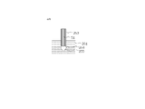
- the nozzle 49 comprises a tubular portion 253 having a flow path 51.
- the tubular portion 253 may have a hollow cylindrical shape.
- the shape of the cross section of the tubular portion 253 orthogonal to the axial direction is a circle.
- the flow path 51 may be connected to the pump 251 (for example, the syringe pump of the pressure generating unit 47) on one end side.
- the pump 251 receives an instruction from the information processing device 170 (for example, the bubble forming unit 200 described later) and supplies air to the flow path 51 or adjusts the amount of gas taken in from the flow path 51 to control the amount of bubbles. Adjust pressure and / or volume.
- the gas-liquid interface 255 is formed at the end 254 of the flow path 51, but both the gas and the liquid are present inside the flow path 51.
- a gas-liquid interface 255 may be formed at the interface between the two inside the flow path 51.
- the gas-liquid interface 255 When the gas-liquid interface 255 comes into contact with an organism adhering to a solid phase such as the inner bottom surface of the container 25 in the liquid 261, the gas-liquid interface 255 exerts a force on the organism by moving the gas-liquid interface 255.
- the organism can be detached from the solid phase and attached to the gas-liquid interface 255.
- the movement of the gas-liquid interface 255 may be performed by moving the nozzle 49 on which the bubbles are formed by the nozzle actuator 40, by moving the liquid, or by changing the volume of the bubbles. You may go.
- the solid phase may be a surface on which adherent cells can be adhered and cultured.
- the solid phase is glass; a resin such as polystyrene; a metal; a surface coated with one or more extracellular matrix components selected from collagen, fibronectin, laminin, polylysine, etc .; various polymers (eg, hydrophilic).
- the surface may be coated with (a polymer capable of controlling the adsorptivity to cells), but the surface is not limited thereto.
- the gas-liquid interface 255 is formed by the interface between the gas and the liquid, but the present invention is not limited to this, and may be changed depending on the phase or substance in contact with the interface. Details of the method for exfoliating the organism from the solid phase will be described later.
- the opening area of the flow path 51 at the end 254 is not particularly limited as long as the size is such that the organism can be manipulated.
- the opening area may be larger than the adhesive area per organism.
- the shape of the end portion 254 is not particularly limited. Further, the inner diameter of the flow path 51 may be the same over the entire length of the tubular portion 253.
- the flow path 51 may be one in which the pump 251 takes in the gas in the bubbles to which the organism is attached, so that the gas-liquid interface 225 is taken into the flow path 51 and the organism is further recovered.
- the nozzle 49 may further include another flow path for collecting the organism, in addition to the flow path 51.
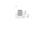
- FIGS. 3A and 3B are examples of schematic views showing the structure of the nozzle 49 in another embodiment.
- the case where the flow path forming the bubble and the flow path for collecting the organism are the same is shown, but in the examples of FIGS. 3A and 3B, the flow path forming the bubble and the organism are shown.
- the case where the flow path for collecting the waste is different is shown.
- the tubular portion 253 of the nozzle 49 has a double structure of an outer cylinder 253a and an inner cylinder 253b. Between the outer cylinder 253a and the inner cylinder 253b is a first flow path 51a through which gas flows, and inside the inner cylinder 253b is a second flow path 51b.
- the first flow path 51a may be a gas supply flow path
- the second flow path 51b may be a gas recovery flow path.
- first flow path 51a and the second flow path 51b of the nozzle 49 may be connected to the first pump 251a and the second pump 251b at one end side, respectively.
- the pressure generating unit 47 may have a first pump 251a and a second pump 251b as syringe pumps, each of which may be controlled by a separate actuator.
- the actuators instructed by the bubble forming unit 200 adjust the amount of gas supplied to or taken in from the first flow path 51a and the second flow path 51b, respectively. Thereby adjusting the pressure and / or volume of the bubbles.
- the shape of the cross section of the tubular portion 253 orthogonal to the axial direction is a donut shape in the first flow path 51a and a circle in the second flow path 51b.
- the first pump 251a is gas in the first flow path 51a.
- bubbles can be formed at the end portion 254.
- a gas-liquid interface 255 is formed at the boundary between the gas and the liquid 261 of the bubbles.
- the second pump 251b may take in the gas-liquid interface 225 into the flow path 51 by sucking bubbles to which the organism adheres through the second flow path 51b, and collect the organism.
- the first pump 251a supplies gas to the first flow path 51a to form bubbles
- the second pump 251b sucks gas through the second flow path 51b to form an organism.
- the second pump 251b supplies gas to the second flow path 51b to form bubbles
- the first pump 251a sucks gas through the first flow path 51a to form an organism. May be collected.
- the first pump 251a and the second pump 251b may be the same syringe pump provided in the pressure generation unit 47. Either one of the first pump 251a and the second pump 251b may be omitted.
- bubbles can be formed in one flow path to attach the organism to the gas-liquid interface 255, and the organism attached in the other channel can be recovered at the same time. Therefore, it has the effect of shortening the time for collecting cells.
- the shape of the cross section of the tubular portion 253 orthogonal to the axial direction is a donut shape in the first flow path 51a and a circle in the second flow path 51b.
- the shape of the cross section is not limited to the donut shape or the circle, and if there are two channels, the organisms can be attached and recovered at the same time.
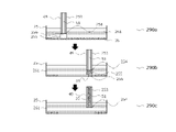
- FIG. 4 is a schematic diagram showing an example of a method for recovering the operation target 35 in the present embodiment.
- the operation target 35 is cultured in the solid phase on the inner bottom surface of the container 25.
- the operation target 35 may be cultured in the liquid 261.
- the operation target 35 is an adherent cell.
- the liquid may be a complete medium.
- the pump 251 supplies gas to the flow path 51 of the nozzle 49 and forms bubbles 256 at the end 254 of the nozzle 49.
- the pump 251 regulates the gas supply and intake to maintain the formed bubbles 256. This makes it possible to more easily operate the operation target 35 by the bubble 256.
- the nozzle actuator 40 moves the nozzle 49 along the surface of the solid phase while keeping the bubble 256 in contact with the operation target 35.
- FIG. 4 describes how the nozzle actuator 40 moves the nozzle 49 from left to right, but the direction in which the nozzle 49 is moved is not limited as long as it is parallel to the surface of the solid phase.
- the operation target 35 can be separated from the solid phase.
- the peeled operation target 35 adheres to the gas-liquid interface 255 of the bubbles 256.
- the bubble forming unit 200 controls the pump 251 to adjust the pressure and / or volume of the gas supplied or taken in to change the size of the bubbles 256, thereby peeling the operation target 35 within a desired range. can do.
- the stage may be moved.
- the operation target 35 adhering to the gas-liquid interface 255 may be recovered by the pump 251 sucking the gas in the flow path 51.
- the bubble 256 formed in the nozzle 49 can be used to selectively peel off the operation target 35 from the solid phase and recover it.
- the adhesion of the adherent cell may be relaxed in advance before the method of FIG. 4 is carried out.
- the relaxation of adhesion of adherent cells can be performed by using a known method, as will be described later.
- FIG. 4 describes an example in which the gas-liquid interface 255 is moved by moving the nozzle 49 to exfoliate and collect cells, but the movement of the gas-liquid interface 255 is not limited to the above example.
- the volume of the bubble 256 may be increased after the bubble 256 is brought into contact with the operation target 35.
- the contact surface between the bubble 256 and the solid phase is widened, and the operation target can be selectively separated from the solid phase and recovered.
- the nozzle actuator 40 may move the nozzle 49 so as to approach the solid phase.
- the contact surface between the bubble 256 and the solid phase expands, and the operation target can be selectively separated from the solid phase and recovered.
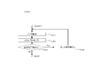
- FIG. 5 shows an example of a specific configuration of the information processing apparatus 170 in the present embodiment.
- the information processing apparatus 170 includes an image pickup control unit 171, a recording unit 190, a bubble forming unit 200, a flow path control unit 250, a liquid control unit 260, and an image processing unit 300.
- the image pickup control unit 171 includes a fluorescent image observation light source 1, an objective lens 6, a fluorescent filter, a transmitted image observation light source 10, a flow path image pickup camera 42, a light source 45, a light source 46, and a camera 60 described in FIGS. 1A and 1B. , And the camera 70, and the like.
- the imaging control unit 171 switches cameras, switches the type of the objective lens 6 in the microscope unit 50, and uses a light source according to the input imaging conditions. Of the switching, switching of the type of fluorescence filter, the position of the stage, and the height of the objective lens 6, necessary adjustments are made for each imaging.
- one or more of the flow path image pickup camera 42, the camera 60, and the camera 70 captures the operation target 35 or the nozzle 49 and operates. Generate an image of the object 35 or the nozzle 49.
- One or more cameras send the generated image data to the image processing unit 300. Further, the generated image data may be recorded in the recording unit 190 and / or output to the output unit 160.
- the recording unit 190 may be, but is not limited to, a memory, an internal hard disk drive, or an external recording medium.
- the information processing device 170 has a central processing unit (CPU), and the CPU realizes the information processing device 170 and the like by executing a computer program recorded in the recording unit 190.
- CPU central processing unit
- the bubble forming unit 200 controls the pressure and volume of the bubbles formed in the flow path 51, the supply of gas, the intake air, the movement of the nozzle 49, and the movement of the stage.
- the bubble forming unit 200 may include all or a part of a nozzle position control unit, a stage position control unit, a volume control unit, an air supply control unit, and an intake air control unit.
- the nozzle position control unit controls the nozzle actuator 40, and controls the operation of the nozzle 49, the air flow in the bubbles accompanying the operation of the nozzle 49, and the movement of the gas-liquid interface 255 accompanying the operation of the nozzle 49. Further, the nozzle position control unit receives the position information of the nozzle 49 from the sensor unit 48 or the nozzle actuator 40.
- the stage position control unit controls the sample actuator 41, and the operation of the stage equipped with the container 25 accommodating the operation target 35, the air flow in the bubbles accompanying the operation of the stage, and the gas-liquid interface 255 accompanying the operation of the stage. Control the movement of. Further, the stage position control unit receives the position information of the stage and the operation target 35 from the sensor unit 48 or the sample actuator 41.
- the volume control unit controls the actuator of the pressure generation unit 47, and controls the pressure and / or volume of the bubbles formed in the flow path 51 by supplying gas from the syringe pump or sucking gas into the syringe pump. Further, the volume control unit receives information on the pressure and / or volume of the bubbles from the nozzle actuator 40, the pressure generation unit 47, or the sensor unit 48.
- the volume control unit or the air supply control unit is a gas supply flow path.
- the first pump 251a connected to the gas supply flow path is controlled, thereby controlling the volume of gas supplied to the gas supply flow path.
- the volume control unit or the air supply control unit receives information on the amount of gas supplied to the gas supply flow path from the nozzle actuator 40, the pressure generation unit 47, or the sensor unit 48.
- the volume control unit or the intake control unit When the nozzle 49 includes a gas supply flow path for supplying (supplying) gas and a gas recovery flow path for recovering (intake) gas, the volume control unit or the intake control unit is connected to the gas recovery flow path.
- the connected second pump 251b is controlled, thereby controlling the amount (volume) of gas taken in from the gas recovery flow path.
- the volume control unit or the intake control unit receives information on the amount of gas taken in from the gas recovery flow path from the nozzle actuator 40, the pressure generation unit 47, or the sensor unit 48.
- the flow path control unit 250 controls the storage, mounting and disposal of the nozzle 49.
- the flow path control unit 250 receives from the input unit 180 an operation instruction regarding mounting and disposal of the nozzle 49 from the operator.
- the flow path control unit 250 takes out the nozzle 49 from the flow path storage unit of the flow path exchange unit 53 according to the received instruction, mounts the nozzle 49 on the nozzle actuator 40, or mounts the nozzle 49 on the nozzle actuator 40.
- An instruction is sent to the flow path exchange unit 53 to remove the nozzle 49 and dispose of it in the flow path disposal unit of the flow path exchange unit 53.
- the liquid control unit 260 controls the storage, replenishment and disposal of liquid.
- the liquid control unit 260 receives an operation instruction regarding replenishment and disposal of the liquid from the operator from the input unit 180.
- the liquid control unit 260 replenishes the container 25 with the liquid stored in the liquid storage unit of the liquid storage unit 54, or collects the liquid contained in the container 25 from the container 25 and liquids according to the received instruction.
- An instruction is sent to the liquid storage unit 54 to dispose of it in the liquid disposal unit of the storage unit 54.
- the image processing unit 300 receives the images captured by the flow path imaging camera 42, the camera 60, and the camera 70 from these cameras.
- the image processing unit 300 may combine a plurality of the received images into one composite image.
- the image processing unit 300 may generate a composite image by synthesizing the fluorescence image captured by the camera 60 and the transmission image captured by the camera 70.
- the image processing unit 300 may record the images received from these cameras and / or the composite image in the recording unit 190 and / or output them to the output unit 160.
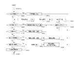
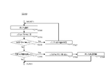
- FIG. 6 is an example of the flow of the method of manipulating an organism in the present embodiment.
- the organism that is the operation target 35 of the present embodiment can be operated by performing the processing of S100 to S680 of FIG.
- the processes of S100 to S680 will be described in order, but at least a part of these processes may be executed in parallel, and each step is not deviated from the gist of the present invention. It may be executed by exchanging.
- the sample actuator 41 accepts an organism to be operated 35.
- the sample actuator 41 mounts a container 25 containing a liquid and an operation target 35 on the stage.
- the lid of the container 25 may be removed in order to operate the operation target 35.
- the lid may be replaced by an actuator that replaces the lid, or may be replaced by the operator's hand.
- the information processing apparatus 170 advances the process to S120.
- the camera 60 or the camera 70 captures a wide range of observation fields including the operation target 35 and generates an image.
- the image pickup control unit 171 sets the observation method to low-magnification transmission image imaging, and sends an instruction to the camera 70 to image the observation field.
- the imaging control unit 171 may set the observation method to fluorescence image imaging and send an instruction to the camera 60 to image the observation field.
- the image pickup control unit 171 may receive input of image pickup conditions from the operator via the input unit 180.
- the camera 60 or the camera 70 images the observation field.
- the image processing unit 300 may record the captured image in the recording unit 190 and / or output it to the output unit 160. After the camera 60 or the camera 70 images the observation field, the image pickup control unit 171 advances the process to S140.
- the information processing apparatus 170 receives input regarding the operation target 35 and the type of operation from the operator via the input unit 180.
- the operation target 35 may be a single cell, a population (colony) of cells, a cytoplasm and / or a cell membrane of a cell, or a spheroid, but is not limited thereto. ..
- the type of operation may be the collection of the operation target 35, the removal of the operation target 35, the holding of the operation target 35, or the compression of the operation target 35. Not limited to.
- FIG. 7A is an example of a GUI (Graphical User Interface) image displayed on the output unit 160 and captured by the camera 60 or the camera 70 in the observation field.
- the cells aaa, bbb, and ccc to be operated are designated as the operation target 35 via the input unit 180.
- the organism to be operated is arbitrarily designated via the input unit 180.
- the removal area and / or the protection area may be provided in the observation field so that the removal area and / or the protection area is selected in the GUI image. By providing the removal region, the risk of recovery of cells other than the recovery cells can be reduced. In addition, by providing the protected area, it is possible to reduce the risk of accidentally removing the recovered cells when removing the cells in the removed area.
- FIG. 7B is a GUI image in which the collection destination and the destination of the cells aaa, bbb, and ccc to be operated 35 displayed on the output unit 160 are designated as A1, A2, and A3 of the 12-hole plate, respectively.
- the movement destination is arbitrarily designated via the input unit 180.
- the destination may be the same plate, a different plate, a petri dish, a microtest tube, a PCR tube, or a conical tube. There may be.
- FIG. 7C shows the ID number of the cell to be operated, the xy coordinates of the operation target 35 on the sample actuator 41, the size of the operation target 35, and the destination of the operation target 35 displayed on the output unit 160.
- This is an example of a GUI image that displays a table listing the above.
- the image processing unit 300 may output the table to the output unit 160 by designating the operation target 35, the moving destination, and the like via the input unit 180.
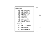
- FIG. 7D is an example of a GUI screen displayed on the output unit 160 for selecting the operation type of the operation target 35.
- the input unit 180 receives an instruction from the operator as to what kind of operation the operation target 35 wants to perform, and inputs the input to the information processing apparatus 170.
- manipulation of cells may be passage, retention or migration of cells, but is not limited to these.
- the operation on the cell may be, but is not limited to, compressing the cell and observing the deep part of the cell.
- FIG. 7D shows an example in which the type of operation is selected by a radio button, but the selection method is not limited to the radio button.
- FIG. 7E is another example of the GUI screen displayed on the output unit 160 for selecting the operation type of the operation target 35.
- the type of operation on the cell may be selected by the pull-down menu.
- the pull-down menu and the radio button may be used together to select the operation type.
- the input unit 180 may send the instruction input from the operator to the information processing apparatus 170 based on the screens shown in FIGS. 7A to 7E. After receiving the instruction from the information processing apparatus 170, the image pickup control unit 171 advances the processing to S160.
- an additional step of relaxing the adhesion of the adherent cell may be performed in advance.
- the information processing apparatus 170 may receive an input as to whether or not to perform a process of relaxing the adhesion.
- the adhesion of adherent cells can be relaxed by using a known method.
- the relaxation of adhesion of adherent cells may be performed by removing the liquid (for example, medium), washing with a buffer solution, and then treating the adherent cells with an adhesion relaxation solution.
- the adhesion relaxation solution may be a proteolytic enzyme solution, a solution containing no metal ions, or a chelating agent solution.
- the adhesion relaxation solution is a trypsin-EDTA solution.
- the relaxation of the adhesion of the adherent cells may be performed by the liquid control unit 260 or may be performed by the operator.
- the process may proceed to S160.
- the step is performed by the operator, the step of accepting the sample of S100 may be started again.
- the adhesive force may be weakened by using a base material that relaxes the adhesion.
- the substrate that relaxes the adhesion may be one that relaxes the adhesion in response to temperature or light irradiation.
- the information processing apparatus 170 receives an input regarding the liquid replacement or addition process from the operator via the input unit 180. For example, when it is desired to adjust the adhesive force between the organism to be operated 35 and the bubble, the information processing apparatus 170 may receive an input to perform a liquid replacement or addition process. When the information processing apparatus 170 is instructed to perform the liquid replacement or addition processing, the information processing apparatus 170 may proceed to the processing to S600. When the information processing apparatus 170 is instructed not to perform the liquid replacement or addition processing, the information processing apparatus 170 may proceed to the processing to S180.
- the liquid control unit 260 replaces the liquid in the container 25 in which the operation target 35 is housed, or adds another liquid to the liquid in the container 25.
- the step of performing the liquid replacement or addition treatment includes the steps of S610 to S630 as shown in FIG.
- the information processing apparatus 170 receives an input from the operator regarding whether or not to remove the liquid via the input unit 180.
- the process proceeds to S615.
- the process proceeds to S620.
- the liquid control unit 260 controls the liquid storage unit 54 to remove the liquid.
- the liquid control unit 260 sends an instruction to the liquid storage unit 54 to collect a preset amount of the liquid contained in the container 25 from the container 25 and dispose of it in the liquid disposal unit of the liquid storage unit 54.
- the liquid storage unit 54 may collect and dispose of the entire amount of the liquid. Instead, the liquid storage unit 54 may collect and dispose of a part (for example, half of the amount) of the liquid.
- the liquid control unit 260 advances the process to S620.
- the liquid control unit 260 sends an instruction to the liquid storage unit 54 to add the adhesive force adjusting reagent to the container 25.
- the adhesive force adjusting reagent is a reagent that adjusts the adhesive force between an organism and bubbles.
- the adhesive force adjusting reagent may be one that changes the concentration of the inorganic salt in the liquid and / or the concentration of the amphipathic substance.
- the adhesion adjusting reagent may be a buffer solution containing or not containing at least one of calcium ion or magnesium ion, may be a basal medium, may be a complete medium, or may be a chelating agent. May be.
- the liquid storage unit 54 replenishes the container 25 with the adhesive force adjusting reagent stored in the liquid storage unit of the liquid storage unit 54.
- an example of replenishing the adhesive force adjusting reagent to the container 25 has been described, but instead of adding the adhesive force adjusting reagent to the container 25, an inorganic salt or an amphipathic substance contained in the liquid is filtered.
- the adhesive force between the organism and the air bubbles may be adjusted by attaching the reagent to the substance and removing it.
- the information processing apparatus 170 receives an instruction from the operator via the input unit 180 regarding whether or not to repeat the above series of operations.
- the information processing device 170 advances the process to S610, and the liquid control unit 260 sends an instruction to the liquid storage unit 54 to remove the liquid in the container 25. ..
- the information processing apparatus 170 advances the process to S180.
- the steps and sub-steps of S600 may be performed by the operator, and in this case, the sample reception step of S100 may be started again.
- the nozzle actuator 40 is equipped with the nozzle 49.
- the information processing apparatus 170 receives an instruction from the operator via the input unit 180 to mount the nozzle 49 on the nozzle actuator 40.
- the flow path control unit 250 takes out the nozzle 49 from the flow path storage unit of the flow path exchange unit 53 according to the instruction, and sends an instruction to the flow path exchange unit 53 to mount the nozzle 49 on the nozzle actuator 40.
- a suitable nozzle 49 may be selected according to the size of the operation target 35, the type of operation, and the like.
- the selection of the nozzle 49 may be specified by the operator via the input unit 180, or may be automatically specified by the flow path control unit 250.
- the flow path control unit 250 advances the process to S200. If the nozzle 49 is not required to be mounted on the nozzle actuator 40, such as when the nozzle 49 is pre-mounted on the nozzle actuator 40 or when the nozzle actuator 40 and the nozzle 49 are integrally formed. The step of S180 may be omitted.
- the nozzle actuator 40 moves the relative position between the nozzle 49 and the operation target 35.
- the bubble forming unit 200 sends an instruction to the nozzle actuator 40 to move the relative position between the nozzle 49 and the operation target 35.
- the step of moving the relative position includes the step of S210 to S225 as shown in FIG. 9A, the step of S230 to S256 as shown in FIG. 9B, or as shown in FIG. 9C. Includes steps S260 to S282.
- FIG. 9A is an example of a flow for moving the relative position between the nozzle 49 and the operation target 35 based on the image obtained by capturing the position of the end portion 254 of the nozzle 49.
- the bubble forming unit 200 sends an instruction to operate the nozzle 49 to a preset position to the nozzle actuator 40.
- the nozzle actuator 40 may be an actuator that controls the xyz position.
- the z position may be a position in the vertical direction (also referred to as a direction along gravity, a vertical direction, or a z direction)
- the x position may be an arbitrary x direction (also referred to as a vertical direction) perpendicular to the z direction.
- the y position may be a position in the y direction (also referred to as a lateral direction) perpendicular to the x direction and the z direction.
- the position of the nozzle 49 is such that the camera 60 and / or the camera 70 is first focused on the bottom surface of the container 25, then the camera 60 and / or the camera 70 is moved upward by an arbitrary distance, and then the nozzle actuator 40 is used.
- the z position may be set by aligning the tip of the nozzle 49 with the focus of the camera 60 and / or the camera 70. For example, any distance may be less than or equal to the radius of the bubble formed at the end 254 of the nozzle 49.
- the distance between the tip of the nozzle 49 and the bottom surface of the container 25 is less than or equal to the radius of the bubbles to be formed, the bubbles come into contact with the bottom surface, so that the organism located on the bottom surface can be operated using the interface of the bubbles. can.
- the xy position of the nozzle 49 can be set by using the nozzle actuator 40 or the sample actuator 41 based on the image obtained by capturing the operation target 35 using the camera 60 and / or the camera 70.
- the position of the nozzle 49 may be set by using the flow path imaging camera 42 instead of the camera 60 and / or the camera 70, or in combination with the camera 60 and / or the camera 70.
- the z position of the nozzle 49 may be adjusted by using the flow path imaging camera 42 to image the tip of the nozzle 49 and the bottom surface of the container 25 from the lateral direction of the nozzle 49 to set the z position.
- the shape of the bubbles or the amount of liquid in the flow path 51 may be confirmed by taking an image from the lateral direction of the nozzle 49 using the flow path imaging camera 42.
- the bubble forming unit 200 advances the process to S215.
- the flow path imaging camera 42 captures an image of the end portion 254 of the nozzle 49.
- the flow path image pickup camera 42 sends the captured image to the image processing unit 300.
- the image processing unit 300 may record the image in the recording unit 190 and / or output it to the bubble forming unit 200.
- the bubble forming unit 200 determines whether or not the position of the nozzle 49 is different from the preset position based on the image of the end portion 254 of the nozzle 49 captured. For example, the bubble forming unit 200 calculates the difference in position from the image of the end portion 254 of the nozzle 49 captured and the image of the end portion 254 of the nozzle 49 at the preset xyz position (that is, the initial position). If the difference is equal to or greater than the threshold value, it is determined that the position of the nozzle 49 is different from the initial position.
- the bubble forming unit 200 advances the process to S225, and if not, advances the process to S300.
- the bubble forming unit 200 determines the amount of movement of the nozzle actuator 40. For example, the bubble forming unit 200 determines the operating amount of the nozzle actuator 40 in order to cause the nozzle actuator 40 to operate the nozzle 49 to a preset xyz position (that is, an initial position), and operates by the determined operating amount. Send instructions. For example, the bubble forming unit 200 may determine the amount of operation according to the magnitude of the difference calculated in S220. The nozzle actuator 40 receives the instruction and proceeds to S210. In the second and subsequent S210s, the bubble forming unit 200 sends an instruction to the nozzle actuator 40 to perform an amount of operation according to the amount of operation.
- the bubble forming unit 200 may send an instruction to move the nozzle actuator 40 so that the relative positions between the nozzle 49 and the operation target 35 are brought closer to each other. At this time, the nozzle actuator 40 can be moved so that the relative position between the nozzle 49 (flow path 51) and the operation target 35 is close to each other.
- FIG. 9B is an example of a flow for moving the relative position between the nozzle 49 and the operation target 35 based on the load sensed by the nozzle actuator 40.
- the bubble forming unit 200 sends an instruction to operate the nozzle 49 to a preset position to the nozzle actuator 40.
- the nozzle actuator 40 may be an actuator that controls the z position. In this case, the z position is controlled based on the load value, contact or proximity information sensed by the nozzle actuator 40.
- the nozzle 49 may be located above the area on the bottom surface of the container 25 where no organism is present. After the nozzle actuator 40 moves the nozzle 49 to a preset position, the bubble forming unit 200 advances the process to S235.
- the sensor unit 48 measures the load, contact or proximity information given by the nozzle actuator 40, and sends the measured value to the bubble forming unit 200.
- load detection when the nozzle 49 reaches the bottom of the container 25, the load sensed by the nozzle actuator 40 increases sharply. Therefore, by measuring the value of the load sensed by the nozzle actuator 40, the bubble forming unit 200 can determine whether or not the nozzle 49 has reached the bottom of the container 25.
- the sensor unit 48 may detect the load while the nozzle actuator 40 moves the nozzle 49 downward. Instead of the sensor unit 48, the nozzle actuator 40 may send the value of the load to be sensed to the bubble forming unit 200.
- the bubble forming unit 200 determines whether or not the measured load value is equal to or less than the set load. If the measured load value is equal to or less than the set load, the bubble forming unit 200 advances the process to S242, and if not, advances the process to S245. As described above, the difference between the load set by the bubble forming unit 200 and the measured load is calculated, and if the value of the difference is equal to or greater than the threshold value, it is determined that the nozzle 49 has not reached the bottom of the container 25.
- the bubble forming unit 200 determines the amount of movement of the nozzle actuator 40. For example, the bubble forming unit 200 determines the operating amount of the nozzle actuator 40 in order to operate the nozzle 49 to a preset position, and sends an instruction to the nozzle actuator 40 to operate by the determined operating amount. For example, the bubble forming unit 200 may determine the amount of operation according to the magnitude of the difference calculated in S240.
- the nozzle actuator 40 receives the instruction and proceeds to S230. In the second and subsequent S230s, the bubble forming unit 200 sends an instruction to the nozzle actuator 40 to perform an amount of operation according to the amount of operation.
- the bubble forming portion 200 sets the initial z position of the nozzle 49.
- the bubble forming portion 200 may set this as the initial z position without moving the z position of the nozzle 49 after the last S230.
- the bubble forming portion 200 may move the nozzle 49 in the z direction by an arbitrary distance preset from the bottom surface of the container 25, and set that position as the initial z position.
- the initial z position of the nozzle 49 is located above the bottom surface by an arbitrary distance. For example, any distance may be less than or equal to the radius of the bubble formed at the end 254 of the nozzle 49.
- the bubble forming unit 200 sends an instruction to operate the nozzle 49 to the preset xyz position (that is, the initial position) to the nozzle actuator 40.
- the movement of the nozzle 49 may be one that moves on the xy plane.
- the control of the z position is controlled based on the value of the load sensed by the nozzle actuator 40.
- the movement of the nozzle 49 may include moving in the z direction as necessary in addition to moving on the xy plane.
- the flow path imaging camera 42 captures an image of the end portion 254 of the nozzle 49.
- the flow path image pickup camera 42 sends the captured image to the image processing unit 300.
- the image processing unit 300 may record the image in the recording unit 190 and / or output it to the bubble forming unit 200.
- the bubble forming unit 200 determines whether or not the position of the nozzle 49 is different from the preset position based on the image of the end portion 254 of the nozzle 49 captured. For example, the bubble forming unit 200 calculates the difference in position from the image of the end portion 254 of the nozzle 49 captured and the image of the end portion 254 of the nozzle 49 at the preset xyz position (that is, the initial position). If the difference is equal to or greater than the threshold value, the bubble forming unit 200 determines that the position of the nozzle 49 is different from the initial position.
- the bubble forming unit 200 advances the process to S256, and if not, proceeds to the process to S300.
- the bubble forming unit 200 determines the amount of movement of the nozzle actuator 40. For example, the bubble forming unit 200 determines the operating amount of the nozzle actuator 40 and operates only the determined operating amount in order to cause the nozzle actuator 40 to operate the nozzle 49 to a preset xyz position (that is, an initial position). Send instructions to do. For example, the bubble forming unit 200 may determine the amount of operation according to the magnitude of the difference calculated in S254. The nozzle actuator 40 receives the instruction, and the bubble forming unit 200 advances the process to S250. In the second and subsequent S250s, the bubble forming unit 200 sends an instruction to the nozzle actuator 40 to perform an amount of operation according to the amount of operation.
- the bubble forming unit 200 may send an instruction to move the nozzle actuator 40 so that the relative positions between the nozzle 49 and the operation target 35 are brought closer to each other. At this time, the nozzle actuator 40 can be moved so that the relative position between the nozzle 49 (flow path 51) and the operation target 35 is close to each other.
- FIG. 9C is an example of a flow for moving the relative position between the nozzle 49 and the operation target 35 based on the internal pressure of the bubble formed at the end portion 254 of the nozzle 49.
- the bubble forming section 200 controls the pressure generating section 47 so as to form bubbles at the end portion 254 of the nozzle 49.
- the bubble forming unit 200 may send an instruction to the nozzle actuator 40 to operate the end portion 254 of the nozzle 49 into the liquid.
- the steps and sub-steps for forming bubbles in S260 may be the same as the steps and sub-steps in S300 described later.
- the bubble forming unit 200 sends an instruction to operate the nozzle 49 to a preset position to the nozzle actuator 40.
- the nozzle actuator 40 may be an actuator that controls the z position. In this case, the z position is controlled based on the value of the internal pressure measured by the sensor unit 48.
- the nozzle 49 may be located above the area on the bottom surface of the container 25 where no organism is present. After the nozzle actuator 40 moves the nozzle 49 to a preset position, the bubble forming unit 200 advances the process to S264.
- the tip of the nozzle 49 may detect the liquid level and control the z position based on the value of the internal pressure measured by the sensor unit 48.
- the volume control unit 200 maintains the internal pressure of the nozzle to be equal to or less than the atmospheric pressure, and when the tip of the nozzle 49 reaches the liquid surface, the sensor unit is affected by the external force due to the deformation of the gas-liquid interface due to the contact with the liquid surface.
- the value of the internal pressure measured by 48 changes. Therefore, the volume control unit 200 can determine whether or not the tip of the nozzle 49 has reached the liquid surface by measuring the value of the internal pressure of the bubbles.
- the volume control unit 200 sends an instruction for z position control with the liquid level as a reference position to the nozzle actuator 40, and the position of the nozzle 49. Can be moved.
- the sensor unit 48 measures the internal pressure of the formed bubbles and sends the measured internal pressure value of the bubbles to the bubble forming unit 200.
- the bubble forming unit 200 can determine whether or not the bubble has reached the bottom of the container 25 by measuring the value of the internal pressure of the bubble.
- the sensor unit 48 may measure the internal pressure while the nozzle actuator 40 moves the nozzle 49 downward, or the volume control unit 200 may control the pressure. , The pressure generating unit 47 may operate.
- the nozzle actuator 40 may measure the internal pressure of the bubble and send the measured internal pressure value to the bubble forming unit 200.
- the bubble forming unit 200 determines whether or not the measured internal pressure value of the bubble is within the preset internal pressure range. If the measured internal pressure value is outside the preset internal pressure range, the bubble forming unit 200 advances the process to S268, and if not, advances the process to S270. As described above, the absolute value of the difference between the internal pressure set by the bubble forming unit 200 and the measured internal pressure of the bubble is calculated, and if the difference is equal to or more than the threshold value, the bubble forming unit 200 has the nozzle 49 at the bottom of the container 25. Is determined to have reached.
- the bubble forming unit 200 determines the amount of movement of the nozzle actuator 40. For example, the bubble forming unit 200 determines the operating amount of the nozzle actuator 40 in order to operate the nozzle 49 to a preset position, and sends an instruction to the nozzle actuator 40 to operate by the determined operating amount. For example, the bubble forming unit 200 may determine the amount of operation according to the magnitude of the difference calculated in S266. The nozzle actuator 40 receives the instruction and proceeds to S262. In the second and subsequent S262s, the bubble forming unit 200 sends an instruction to the nozzle actuator 40 to perform an amount of operation according to the amount of operation.
- the bubble forming section 200 controls the pressure generating section 47 so as to remove bubbles from the end portion 254 of the nozzle 49.
- the steps and sub-steps for removing air bubbles in S270 may be the same as the steps and sub-steps in S500 described later.
- the bubble forming portion 200 sets the initial z position of the nozzle 49.
- the step of S272 may be the same as the step of S245. After the bubble forming section 200 sets the initial z position of the nozzle 49, the bubble forming section 200 advances the process to S274.
- the bubble forming unit 200 sends an instruction to operate the nozzle 49 to the preset xyz position (that is, the initial position) to the nozzle actuator 40.
- the movement of the nozzle 49 may be one that moves on the xy plane.
- the control of the z position is controlled based on the value of the internal pressure measured by the nozzle actuator 40.
- the movement of the nozzle 49 may include moving in the z direction as necessary in addition to moving on the xy plane.
- the flow path imaging camera 42 captures an image of the end portion 254 of the nozzle 49.
- the flow path image pickup camera 42 sends the captured image to the image processing unit 300.
- the image processing unit 300 may record the image in the recording unit 190 and / or output it to the bubble forming unit 200.
- the bubble forming unit 200 determines whether or not the position of the nozzle 49 is different from the preset position based on the image of the end portion 254 of the nozzle 49 captured. For example, the bubble forming unit 200 calculates the difference in position from the image of the end portion 254 of the nozzle 49 captured and the image of the nozzle end portion 254 at the preset xyz position (that is, the initial position), and the difference is If it is equal to or more than the threshold value, the bubble forming unit 200 may determine that the position of the nozzle 49 is different from the initial position.
- the bubble forming unit 200 advances the process to S282, and if not, proceeds to the process to S300.
- the bubble forming unit 200 determines the amount of movement of the nozzle actuator 40. For example, the bubble forming unit 200 determines the operating amount of the nozzle actuator 40 and operates only the determined operating amount in order to cause the nozzle actuator 40 to operate the nozzle 49 to a preset xyz position (that is, an initial position). Send instructions to do. For example, the bubble forming unit 200 may determine the amount of operation according to the magnitude of the difference calculated in S280. The nozzle actuator 40 receives an instruction, and the bubble forming unit 200 advances the process to S274. In the second and subsequent S274s, the bubble forming unit 200 sends an instruction to the nozzle actuator 40 to perform an amount of operation according to the amount of operation.
- the bubble forming unit 200 may send an instruction to move the nozzle actuator 40 so that the relative positions between the nozzle 49 and the operation target 35 are brought closer to each other. At this time, the nozzle actuator 40 can be moved so that the relative position between the nozzle 49 (flow path 51) and the operation target 35 is close to each other.
- the bubble forming unit 200 controls the pressure generating unit 47 so as to expand the gas-liquid interface 255.
- expanding the gas-liquid interface 255 may include forming bubbles.
- the bubble forming unit 200 may send an instruction to the nozzle actuator 40 to operate the end portion 254 of the nozzle 49 into the liquid.
- the step of expanding the gas-liquid interface 255 includes steps S320 to S342 as shown in FIG. 10A, or includes steps S370 to S392 as shown in FIG. 10B.
- FIG. 10A is an example of a flow for expanding the gas-liquid interface 255 based on an image obtained by capturing the position of the end portion 254 of the nozzle 49.
- the bubble forming unit 200 sends an instruction to expand (form a bubble) the gas-liquid interface 255 at the tip of the flow path 51 to the pressure generating unit 47 connected to the flow path 51.
- the bubble forming unit 200 pushes the plunger of the syringe pump to the pressure generating unit 47 by a preset distance, or pushes the plunger of the syringe pump until the pressure reaches the preset pressure.
- the gas extruded from the syringe pump is supplied to the flow path 51, and the gas is discharged from the end portion 254, so that the gas-liquid interface 255 at the tip of the flow path 51 is expanded (bubbles are formed). ..
- the bubble forming unit 200 advances the treatment to S330.
- the flow path imaging camera 42 captures an image of bubbles formed at the end 254 of the nozzle 49.
- the flow path image pickup camera 42 sends the captured image to the image processing unit 300.
- the image processing unit 300 may record the image in the recording unit 190 and / or output it to the bubble forming unit 200.
- the bubble forming unit 200 determines whether or not the shape of the formed bubble is different from the preset shape of the bubble based on the image of the captured bubble.
- the bubble forming portion 200 is based on information such as the set internal pressure in the nozzle 49, the inner diameter of the end portion 254 of the nozzle 49, the wettability of the nozzle 49 (contact angle of the liquid), the type of the liquid, and the type of the gas. Predict the shape of the bubbles formed at the end 254 of. For example, the bubble forming unit 200 determines whether or not the formed bubble shape is different from the set bubble shape by comparing the image of the captured bubble with the bubble shape predicted from the above information. You can do it.
- the bubble forming unit 200 proceeds to the process to S342, and if not, proceeds to S400.
- the bubble forming unit 200 determines the operating amount of the plunger of the syringe pump of the pressure generating unit 47. For example, the bubble forming unit 200 forms the bubbles formed at the tip of the nozzle 49 so as to have a preset shape, so that the operating amount of the plunger of the syringe pump of the pressure generating unit 47 (for example, the syringe pump). Determine the distance to push or pull the plunger).
- the bubble forming unit 200 sends an instruction to the pressure generating unit 47 so that the operation is performed by the determined operation amount. For example, the bubble forming unit 200 may determine the amount of operation according to the magnitude of the difference calculated in S340.
- the operating amount may be the operating amount of the actuator of the pressure generating unit 47, or may be an additional pressure applied to the syringe pump.
- the pressure generation unit 47 receives the instruction, and the bubble forming unit 200 advances the process to S320. In the second and subsequent S320s, the pressure generation unit 47 performs an amount of operation according to the amount of operation.
- FIG. 10B is an example of a flow that expands the gas-liquid interface 255 based on the internal pressure in the nozzle 49.
- the step of S370 may be the same as the step of S320. After finishing S370, the bubble forming unit 200 advances the process to S380.
- the sensor unit 48 measures the internal pressure in the nozzle 49, and sends the measured internal pressure value in the nozzle 49 to the bubble forming unit 200.
- the nozzle actuator 40 may measure the internal pressure in the nozzle 49 and send the measured internal pressure value to the bubble forming unit 200.
- the bubble forming unit 200 determines whether or not the measured internal pressure value in the nozzle 49 is within the preset internal pressure range. If the measured internal pressure value is outside the set internal pressure range, the bubble forming unit 200 advances the process to S392, and if not, the process proceeds to S400. For example, the bubble forming unit 200 may calculate the difference between the preset internal pressure and the measured internal pressure in the nozzle 49, and if the difference is equal to or greater than the threshold value, it may be determined that the set internal pressure has not been reached.
- the bubble forming unit 200 sets the operating amount of the plunger of the syringe pump of the pressure generating unit 47 (for example, the distance to push or pull the plunger of the syringe pump) in order to realize the internal pressure in the set nozzle 49. decide.
- the bubble forming unit 200 sends an instruction to the pressure generating unit 47 so that the operation is performed by the determined operation amount.
- the bubble forming unit 200 may determine the amount of operation according to the magnitude of the difference calculated in S390.
- the operating amount may be the operating amount of the actuator of the pressure generating unit 47, or may be an additional pressure applied to the syringe pump.
- the pressure generation unit 47 receives the instruction, and the bubble forming unit 200 advances the process to S370. In the second and subsequent S370s, the pressure generation unit 47 performs an operation in an amount corresponding to the operation amount.
- the gas-liquid interface operation unit 101 executes an operation on the operation target 35.
- the bubble forming unit 200 sends an instruction to the gas-liquid interface operation unit 101 to execute an operation to the operation target 35 based on the instruction received via the input unit 180.
- the step of performing the operation includes the steps of S410 to S460, as shown in FIG. 11A.
- the operation may be removal of unwanted cells, recovery or migration of cell membranes and / or cell membranes, recovery of cells, retention of cells, or compression of cells.
- FIG. 11A is an example of a flow for executing an operation on the operation target 35.
- FIG. 11A describes an example in which the operation target 35 is a cell.
- the operation target 35 is not limited to cells, but may be other organisms.
- the information processing apparatus 170 proceeds to process in S412. If the S410 is instructed not to remove unnecessary cells in the S140, the information processing apparatus 170 advances the process to the S420.
- the bubble forming portion 200 attaches cells to the formed bubbles and removes them.
- the bubble forming unit 200 sends an instruction to the nozzle actuator 40 to move the position of the nozzle 49 to the position where the target cell exists in the xyz direction.
- the bubble forming unit 200 may move the nozzle 49 and / or the stage to bring the gas-liquid interface 255 of the bubble into contact with the cell.
- the nozzle actuator 40 or the sample actuator 41 identifies the position where the target cell exists from the image obtained by capturing the target cell by the camera 60 or the camera 70, and sets the center of the nozzle 49. Move to the desired position. After the cells are brought into contact with the gas-liquid interface 255 of the bubbles, the nozzle actuator 40 collects the cells of interest in the flow path 51 as shown in FIGS. 290a to 290c, and the liquid storage unit 54 collects these cells. Cells may be discarded in the liquid disposal section of the liquid storage section 54.
- the bubble forming unit 200 forms a gas-liquid interface 255 having a predetermined size in the step and the sub-step of S300, and controls the expansion of the gas-liquid interface 255 to control the cells. It may be attached to the liquid interface 255 and peeled off. After the liquid control unit 260 removes unnecessary cells, the bubble forming unit 200 advances the treatment to S500.
- the bubble forming unit 200 separates the cytoplasm and / or the cell membrane using the formed bubbles, attaches them to the bubbles, and collects them.
- the bubble forming unit 200 controls the pressure generating unit 47 to form a bubble at the tip of the flow path 51, and attaches a target cell to the bubble.
- the bubble forming portion 200 presses the cell with the bubble to separate only the cytoplasm and / or the cell membrane portion and attach it to the bubble.
- the bubble forming unit 200 controls the pressure generating unit 47 to increase the internal pressure of the bubble, expands the bubble, or controls the nozzle actuator 40 to move the nozzle 49 toward the cell, and the bubble is formed. Presses against the cells to compress them.
- the bubble-forming unit 200 then separates the cytoplasm and / or the cell membrane portion from the cell by moving a portion of the cell that swells out of the cell due to compression so as to separate it from the cell at the gas-liquid interface.
- the bubble forming unit 200 controls the nozzle actuator 40 or the pressure generating unit 47 to cut out the necessary cytoplasm and / or the cell membrane of the operation target 35.
- the bubble forming unit 200 may send an instruction to the nozzle actuator 40 to move the nozzle 49 from the initial position to the position where the target cell exists in the xyz direction. After the nozzle actuator 40 moves to the target position of the nozzle 49, the bubble forming unit 200 moves the nozzle 49 and / or the stage by the nozzle actuator 40 or the sample actuator 41 to move the air bubbles.
- the liquid interface 255 may be brought into contact with the cell.
- the bubble forming unit 200 identifies the position where the target cell exists from the image captured by the camera 60 or the camera 70, and aligns the center of the nozzle 49 with the target position.
- the nozzle actuator 40 is controlled to move the nozzle 49.
- the location of the target cell may be specified by the operator.
- the bubble forming unit 200 may receive an input from the input unit 180 by the operator about the position where the target cell exists and specify the position.
- the cell membrane has a portion showing relatively soft physical characteristics and a portion showing relatively hard physical properties due to the difference in the composition of lipids constituting the membrane component.
- the bubble forming unit 200 controls the nozzle actuator 40 or the pressure generating unit 47 to press the cells with the bubbles.
- the compression of the cell by the bubble is controlled so that the bubble forming unit 200 forms the gas-liquid interface 255 having a predetermined size in the step and the sub-step of S300 and expands the gas-liquid interface 255.
- the cells may be attached to the gas-liquid interface 255 and compressed.
- the swelled part is attached using the gas-liquid interface 255, and the cell membrane is separated by moving it in a direction away from the cell, and the cell membrane is separated. May be collected in the flow path 51 while being adhered to the gas-liquid interface 255. Further, when the cell membrane is cut in this way, the cell membrane swells by being pushed by the cytoplasm from the inside, so that the separated cell membrane contains the cytoplasm component inside, and the cytoplasm component can be collected in the flow path 51. .. After the nozzle actuator 40 has separated the required cytoplasm and / or cell membrane portion, the bubble forming unit 200 proceeds to process S434.
- FIG. 11B shows how the cytoplasm and cell membrane are recovered from cells according to the present embodiment.
- the bubble forming section 200 controls the pressure generating section 47 and the nozzle actuator 40 to bring HeLa cells (human cervical cancer cells) cultured in the solid phase of the container 25 into the gas-liquid interface 255 of the bubbles.
- the relative positions of the cells and the nozzle 49 were brought closer to each other (802a).
- the bubble forming unit 200 pressed the cell by controlling the gas-liquid interface 255 to be pressed against the cell (802b). At this time, it was observed that the soft portion of the cell membrane swelled outward due to the compression (arrow of 802b).
- the cytoplasm and cell membrane in the swollen part are separated by moving the gas-liquid interface 255 in the direction away from the cell (arrow of 802c). Finally, the separated cytoplasm and cell membrane were attached to the gas-liquid interface 255 and recovered (802d).
- the operation shown in FIG. 11B the operation may be performed by enlarging the gas-liquid interface 255, the operation may be performed by moving the nozzle 49, or the operation may be performed by moving the stage. You may go.
- the bubble forming unit 200 determines whether or not the instruction received in S140 continuously includes collecting the cytoplasm and / or the cell membrane of the operation target 35. If the judgment is positive, the bubble forming unit 200 proceeds to S435, and if the judgment is negative, the process proceeds to S500.
- the bubble forming section 200 controls the pressure generating section 47 so as to remove the bubbles formed in the end portion 254 of the nozzle 49.
- the operation target 35 may be collected at the same time.
- the operation target 35 may be recovered in the liquid existing in the flow path 51.
- the steps and sub-steps for removing air bubbles in S435 may be the same as the steps and sub-steps in S500, and the details thereof will be described later.
- the bubble forming unit 200 controls the pressure generating unit 47 and the nozzle actuator 40 so as to take in gas in order to form new bubbles at the end portion 254 of the nozzle 49.
- the bubble forming unit 200 sends an instruction to the nozzle actuator 40 to take out the nozzle 49 from the liquid.
- the pressure generator 47 may pull the plunger of the syringe pump to draw in the required amount of gas.
- the bubble forming unit 200 controls the pressure generating unit 47 so as to form a new bubble at the end portion 254 of the nozzle 49.
- the contents of S300 already described may be applied to the steps and substeps of S437.
- the bubble forming section 200 advances the process to the step of S420.
- the bubble forming unit 200 determines whether or not it has been instructed to collect cells in S140. If the judgment is affirmative, the bubble forming unit 200 proceeds to S432, and if the judgment is negative, the bubble forming unit 200 proceeds to the process to S440.
- the bubble forming unit 200 controls the pressure generating unit 47 to form bubbles and attach cells to the bubbles.
- the bubble forming unit 200 may exfoliate the cells attached to the bubbles from the solid phase, if necessary.
- the bubble forming unit 200 sends an instruction to the nozzle actuator 40 to move the nozzle 49 from the initial position to the position where the target cell exists in the xyz direction. After the nozzle actuator 40 moves to the target position of the nozzle 49, the bubble forming unit 200 controls the pressure generating unit 47 to supply gas to the flow path 51 and form bubbles at the tip of the flow path 51. Let me. Next, the bubble forming unit 200 may control the nozzle actuator 40 or the sample actuator 41 to move the nozzle 49 or the stage to bring the gas-liquid interface 255 of the bubble into contact with the cell.
- the nozzle actuator 40 or the sample actuator 41 identifies the position where the target cell exists from the image obtained by capturing the target cell by the camera 60 or the camera 70, and sets the center of the nozzle 49. Move to the desired position.
- the bubble forming unit 200 controls the pressure generating unit 47 to supply gas to the flow path 51 to supply gas to the flow path 51. Bubbles are formed at the tip of 51.
- the bubble forming unit 200 may move the nozzle 49 and / or the stage by the nozzle actuator 40 or the sample actuator 41 to bring the gas-liquid interface 255 of the bubble into contact with the cell.
- the nozzle actuator 40 may detach the cells as necessary by moving the gas-liquid interface 255 or the like.
- the bubble forming unit 200 controls the pressure generating unit 47 to form a bubble and attaches cells to the bubble
- the bubble forming unit 200 proceeds to the process of S434.
- the contents already described may be applied to the steps after S434.
- what is continuously collected is not limited to cytoplasm only or cells, but may be both cytoplasm and cells.
- FIG. 11C shows a state in which the established cells are attached to the bubbles and detached according to the present embodiment.
- the bubble forming unit 200 controls the pressure generating unit 47 and the nozzle actuator 40 (or the sample actuator 41 instead of the nozzle actuator 40) to generate bubbles in the HeLa cells cultured in the solid phase of the container 25.
- the relative positions of the cells and the nozzle 49 were brought closer to each other so as to be in contact with the gas-liquid interface 255 (804a).
- the cells then contacted the gas-liquid interface 255 of the bubbles (804b).
- the nozzle actuator 40 moved the gas-liquid interface 255 (804c), and the cells were attached to the gas-liquid interface 255 and detached (804d).
- the operation shown in FIG. 11C is performed, the operation may be performed by enlarging the gas-liquid interface 255, the operation may be performed by moving the nozzle 49, or the operation may be performed by moving the stage. You may go.
- FIG. 11D shows a schematic diagram in the case of repeating S430 ⁇ S432 ⁇ S434 ⁇ S435 ⁇ S436 ⁇ S437.
- the bubble forming unit 200 controls the pressure generating unit 47 and supplies air to a syringe pump (not shown) to supply air to the end of the nozzle 49. Bubbles are formed in 254.
- the cells adhering to the bottom surface of the container 25 are attached to the gas-liquid interface 255 of the bubbles and peeled off, and the gas is sucked into the syringe pump to be collected in the flow path 51.
- the nozzle actuator 40 pulls the nozzle 49 out of the liquid, and the syringe pump sucks gas (eg, air) into the flow path 51.
- the syringe pump supplies air to the end portion 254 of the nozzle 49 to form new bubbles and adheres to the bottom surface of the container 25.
- the cells are collected by adhering them to the gas-liquid interface 255 of the bubbles.
- the bubble forming unit 200 controls the pressure generating unit 47 and the nozzle actuator 40 so that the two cells (groups) are continuously collected in the flow path 51 without being mixed via the gas. can do.
- a photograph of two cells (populations) collected by this method with air in between is also shown.
- the operation of FIG. 11D may be performed by moving the stage instead of moving the nozzle 49.
- FIG. 11E shows the state of passage in which the collected cell lines were collected and the collected cell lines were cultured according to the present embodiment.
- the bubble forming unit 200 controls the pressure generating unit 47 and the actuator 40 for the nozzle to control HeLa cells (human cervical cancer cells, 820a) and HT29 cells (human colon cancer cells, 820b), which are established cells.
- HeLa cells human cervical cancer cells, 820a
- HT29 cells human colon cancer cells, 820b
- Kato III cells human gastric ring cell cancer cells, 820c
- the cells were cultured for 1.5 days (820a and 820b) and 2 days (820c). It was confirmed that all the cells were proliferating after passage.
- the operation may be performed by moving the nozzle 49, or the operation may be performed by moving the stage.
- FIG. 11F shows a state in which iPS cells were recovered and the recovered iPS cells were subcultured according to the present embodiment.
- the bubble forming section 200 controls the pressure generating section 47 and the actuator 40 for the nozzle to attach, detach and recover the cultured iPS cell colonies from the solid phase of the container 25 using the gas-liquid interface 255 of the bubbles. After releasing into a liquid medium in another container and culturing for 4 days, a transmission image was observed.
- iPS cells subcultured by a normal cell passage method mechanical passage
- the iPS cells of this embodiment and Comparative Examples were stained with alkaline phosphatase. Furthermore, the iPS cells of the present embodiment and the comparative example were subcultured three times, and after culturing for 30 days, the iPS cells of the present embodiment and the comparative example were stained with alkaline phosphatase. As a result, the iPS cells of the present embodiment (831a cultured for 10 days, 832a cultured for 30 days) and the iPS cells of the comparative example (831b cultured for 10 days, 832b cultured for 30 days). No difference in stainability was observed between the two.
- alkaline phosphatase is highly expressed in iPS cells that are undifferentiated and maintain their self-renewal ability. That is, according to the present embodiment, even if the iPS cells are exfoliated and recovered using the gas-liquid interface 255, the iPS cells are proliferated while maintaining the undifferentiated state without affecting the maintainability of the undifferentiated ability. Was done.
- the operation may be performed by moving the nozzle 49, or the operation may be performed by moving the stage.
- FIG. 11G shows how the established cells were recovered and the recovered cells were analyzed according to the present embodiment.
- HeLa cells which are cell lines, were exfoliated and recovered from the solid phase of the container 25 using the gas-liquid interface 255 of bubbles.
- the bubble forming unit 200 selects 1 cell, 4 cells, and 8 cells from the solid phase and detaches them using the gas-liquid interface 255 of the bubbles.
- Each of these cells was harvested with 7.5 nL of liquid medium (835a).
- the recovered HeLa cells were then released into 12.5 ⁇ L cytolytic reagents to lyse the cells (835b).
- CDNA was synthesized from ⁇ -actin mRNA in a cytolytic solution in which HeLa cells were lysed, and a PCR reaction was performed (835c). As a result, it was possible to detect the amount of cDNA that was roughly proportional to the number of recovered cells. That is, according to this embodiment, it was possible to recover one cell or an arbitrary number of cells using the gas-liquid interface 255 and perform molecular biological analysis.
- the operation may be performed by moving the nozzle 49, or the operation may be performed by moving the stage.
- the bubble forming unit 200 determines whether or not it has been instructed to hold and image the cells in S140. If the judgment is affirmative, the bubble forming unit 200 advances the process to S442, and if the determination is negative, the bubble forming unit 200 proceeds to the process to S450.
- the bubble forming unit 200 attaches cells to the formed bubbles and controls to hold the attached cells. For example, the bubble forming unit 200 sends an instruction to the nozzle actuator 40 to move the nozzle 49 from the initial position to the position where the target cell exists in the xyz direction. After the nozzle actuator 40 moves to the target position of the nozzle 49, the bubble forming unit 200 controls the pressure generating unit 47 to supply gas to the flow path 51 and generate bubbles at the tip of the flow path 51. To form. The bubble forming unit 200 may move the nozzle 49 and / or the stage by the nozzle actuator 40 or the sample actuator 41 to bring the gas-liquid interface 255 of the bubble into contact with the cell.
- the nozzle actuator 40 or the sample actuator 41 identifies the position where the target cell exists from the image obtained by capturing the target cell by the camera 60 or the camera 70, and sets the center of the nozzle 49. Move to the desired position. After contacting the cell with the gas-liquid interface 255 of the bubble, the bubble forming unit 200 proceeds to the treatment to S444.
- the position where the target cell exists may be specified by the operator.
- the bubble forming unit 200 may receive an input from the input unit 180 by the operator about the position where the target cell exists and specify the position.
- the case where the tip surface of the bubble is brought into contact with the cell is described, but the contact between the bubble and the cell may be performed by bringing the side surface of the bubble into contact with the cell.
- the nozzle actuator 40 or the sample actuator 41 may move so that the center of the nozzle 49 is aligned with the vicinity of the target cell.
- the nozzle actuator 40 may detach the cells as necessary by moving the gas-liquid interface 255 or the like.
- the image pickup control unit 171 sends an instruction to the camera 60 or the camera 70 to image the cells held in the bubbles.
- the camera 60 or the camera 70 captures an image and sends the image to the image processing unit 300.
- the image processing unit 300 may record the image in the recording unit 190 and / or output it to the bubble forming unit 200.
- the bubble forming unit 200 After imaging the cells held by the camera 60 or the camera 70, the bubble forming unit 200 advances the processing to S500.
- FIG. 11H is a schematic diagram showing a state in which the established cells are held at the gas-liquid interface 255 of bubbles and observed. Since floating cells or weakly adhered cells move freely in the culture solution with slight vibration, it is difficult to observe them as they are with a microscope or the like.
- the bubble forming unit 200 controls the nozzle actuator 40 to put the end portion 254 of the nozzle 49 into the liquid medium in the container 25 for culturing the floating cells (operation target 35).
- the pressure generating unit 47 supplies gas to the flow path 51 to form bubbles at the tip of the nozzle 49, forming a gas-liquid interface 255.
- the bubble forming unit 200 controls the nozzle actuator 40 or the pressure generating unit 47 to attach the floating cells to be operated to the formed gas-liquid interface 255.
- the pressure generating unit 47 controls the internal pressure of the bubble to temporarily hold the cell at the gas-liquid interface 255 of the bubble.
- the pressure generating unit 47 sucks gas from the flow path 51 to reduce the bubbles.
- the cells held in that state can be observed using a microscope or the like.
- the pressure generating unit 47 may hold the cells without shrinking the bubbles, and observe the held cells using a microscope or the like.
- the cells can be observed without moving.
- the bubble forming unit 200 controls the nozzle actuator 40 to put the end portion 254 of the nozzle 49 into the liquid medium of the container 25 for culturing the adherent cells (operation target 35).
- the pressure generating unit 47 supplies gas to the flow path 51 to form bubbles at the tip of the nozzle 49, forming a gas-liquid interface 255.
- the bubble forming unit 200 controls the gas-liquid interface 255 by controlling the nozzle actuator 40 or the pressure generating unit 47, and attaches and detaches the cells to the gas-liquid interface 255.
- the pressure generating unit 47 temporarily holds the cells at the gas-liquid interface 255 of the bubbles.
- the pressure generating unit 47 sucks gas from the flow path 51 to reduce the bubbles.
- the cells held in such a state can be observed all at once using a microscope or the like because the cells are present in a narrow range of the plane at the same z position.
- the field of view to be observed can be reduced by holding the cells at the gas-liquid interface of the bubbles.
- Kato III cells which are floating cells, were scattered on the solid phase, and some cells were attached to the gas-liquid interface 255 (844a).
- the bubble forming unit 200 controls the internal pressure of the bubble via the pressure generating unit 47 to hold the cell at the gas-liquid interface 255 while reducing the bubble, and when the held cell is focused, the surrounding cells are focused.
- the surrounding cells move, but the cells held at the gas-liquid interface 255 do not move, so that the held cells can be easily observed with a microscope (844c).
- the bubble forming unit 200 determines whether or not the cell is instructed to be compressed and imaged in S140. The bubble forming unit 200 proceeds to S452 if the judgment is affirmative, and proceeds to S460 if the judgment is negative.
- the bubble forming unit 200 controls the pressure generating unit 47 and the nozzle actuator 40 to press the cells using the bubbles.
- the bubble forming unit 200 controls the pressure generating unit 47 to form a bubble at the tip of the flow path 51, and brings the bubble into contact with the cell to be operated.
- the operation may be performed by moving the nozzle 49, or the operation may be performed by moving the stage.
- the bubble forming unit 200 sends an instruction to the nozzle actuator 40 to move the nozzle 49 from the initial position to the position where the target cell exists in the xyz direction.
- the bubble forming unit 200 identifies the position where the target cell exists from the image captured by the camera 60 or the camera 70, and aligns the center of the nozzle 49 with the target position.
- the nozzle actuator 40 is controlled to move the nozzle 49.
- the position where the target cell exists may be specified by the operator.
- the bubble forming unit 200 may receive an input from the input unit 180 by the operator about the position where the target cell exists and specify the position. Further, the contact between the bubble and the cell may be performed by contacting the tip surface of the bubble with the cell, or by contacting the side surface of the bubble with the cell. When the tip surface of the bubble is brought into contact with the cell, the nozzle actuator 40 or the sample actuator 41 may be moved so that the center of the nozzle 49 is aligned directly above the target cell.
- the nozzle actuator 40 or the sample actuator 41 may be moved so that the center of the nozzle 49 is aligned with the vicinity of the target cell, in this case the cell. Bubbles can be formed on the side and the nozzle 49 can be moved to gradually press the cells from the side.
- the bubble forming unit 200 controls the pressure generating unit 47 to supply gas to the flow path 51 at the target position. Bubbles are formed at the tip of the flow path 51.
- the bubble forming unit 200 may move the nozzle 49 and / or the stage by the nozzle actuator 40 or the sample actuator 41 to bring the gas-liquid interface 255 of the bubble into contact with the cell.
- the gas-liquid interface 255 may be brought into contact with the cell by moving the stage.
- the cell may be brought into contact with the gas-liquid interface 255 by controlling the bubble forming unit 200 to expand the gas-liquid interface 255 via the pressure generating unit 47.
- the bubble forming unit 200 operates the plunger of the syringe pump of the pressure generating unit 47 with a preset operating amount to form a bubble having a preset volume, and then the bubble forms cells in the nozzle 49.
- the nozzle 49 and / or the stage is moved by the nozzle actuator 40 or the sample actuator 41 so as to be located at the pressing position.
- the bubble forming unit 200 controls the pressure generating unit 47 to expand the bubbles formed at the tip of the flow path 51, or controls the nozzle actuator 40 to move the nozzle 49 toward the cells.
- the cells may be compressed by pressing the bubbles against the cells.
- the bubble forming unit 200 moves the nozzle 49 very close to the cell and then controls the pressure generating unit 47 to form a bubble having a preset volume at the tip of the flow path 51.
- the cells may be compressed.
- the image pickup control unit 171 sends an instruction to the camera 60 or the camera 70 to image the compressed cells.
- the camera 60 or the camera 70 captures an image and sends the image to the image processing unit 300.
- the image processing unit 300 may record the image in the recording unit 190 and / or output it to the output unit 160.
- the sensor unit 48 or the nozzle actuator 40 may measure the pressure at which the bubbles press the cells and send the measured pressure value to the bubble forming unit 200.
- the camera 60 or the camera 70 may repeatedly perform image imaging while changing the pressure at which the bubble forming portion 200 presses the cells. The pressure that presses on the cells can be changed by the bubble forming unit 200 controlling the pressure generating unit 47 to change the internal pressure and / or volume of the bubbles.
- the bubble forming section 200 controls the pressure generating section 47 after moving the nozzle 49 very close to the cell to form a bubble at the tip of the flow path 51, and adjusts the internal pressure and / or volume of the bubble. It may be varied to hold or change the pressure on the cell while compressing the entire cell or different parts of the cell. Depending on the composition and distribution of the cell membrane or intracellular organelle, it is expected that different parts of the cell will have different hardness. In this way, the composition and distribution of the cell membrane or intracellular organelle in the cell can be analyzed using the pressure and / or the observation image at the time of compression by the bubble as an index.
- the thickness of the cells becomes thinner, and the structures deep inside the cells can be clearly observed, and by spreading laterally, the structures that were close to each other can be separated and observed individually. Become.
- the bubble forming unit 200 advances the process to S500.
- FIG. 11I shows a state in which the established cells were pressed using bubbles and the deep part of the cells was observed according to the present embodiment.
- the cell in order to observe the structure in the deep part of the cell, the cell is fixed with formalin or methanol, and the cell is sliced thinly for observation, or it is observed by using a special microscope specialized for deep observation. Has been done. According to this embodiment, it is possible to observe the deep structure of a cell in a living state without using a special microscope. Furthermore, in the spheroid (850a) before compression, it is difficult for the nuclei to be in close contact with each other to recognize individual nuclei, but in the spheroid (850b) observed by compression, the spheroids spread in the vertical and horizontal directions, which is sufficient for the nuclei. There was a lot of space, and the nucleus could be recognized independently.
- a microscopic system in which an optical system and a fluorescent labeling method have been devised in order to independently recognize two or more organelles in close proximity inside a cell has been researched and developed, and is called a super-resolution microscope.
- These microscopy techniques increase the resolution, but narrow the field of view and increase the imaging time.
- two or more organelles in close proximity inside a cell can be independently imaged in a living state without using a special microscope and with a short imaging time while maintaining an observation field of view. Can be recognized. It is also possible to reproduce the original three-dimensional structure of the cell from the observed image of the compressed cell and the mechanics information.
- the bubble forming unit 200 controls the gas-liquid interface operating unit 101 so that the necessary operations other than S410 to S450 among the instructions received in S140 are performed on the operation target 35.
- the operation may be evaluation of cell adhesion, induction of cell differentiation, or the like, which will be described later.
- the bubble forming unit 200 advances the process to S500.
- the bubble forming unit 200 controls the pressure generating unit 47 so as to reduce the gas-liquid interface 255. Reducing the gas-liquid interface 255 may include removing air bubbles. Here, when the bubbles are reduced or removed, the operation target 35 may be recovered at the same time.
- the steps of reducing the gas-liquid interface 255 include steps S510 to S544, as shown in FIG. 12A, or include steps S560 to S594, as shown in FIG. 12B.
- FIG. 12A is an example of a flow for reducing the gas-liquid interface 255 based on an image obtained by capturing the position of the end portion 254 of the nozzle 49.
- the bubble forming unit 200 controls the pressure generating unit 47 to cause the flow path 51 to perform a suction operation, and to take in the gas-liquid interface 255 from the tip of the flow path 51. At this time, the liquid is also taken in at the same time.
- the liquid to be taken in may be used to separate the operation target 35 from the gas-liquid interface 255.
- the liquid to be taken in may be a liquid contained in the container 25 (for example, a medium) or another liquid stored in the liquid storage unit 54.
- the bubble forming unit 200 pulls the plunger of the syringe pump by the preset distance to the pressure generating unit 47, or pulls the plunger of the syringe pump until the pressure reaches the preset pressure. Send instructions to 47 actuators.
- the pressure generation unit 47 sucks the gas.
- the gas-liquid interface 255 is reduced (air bubbles are removed), and the gas-liquid interface 255 is taken into the flow path 51.
- the bubble forming unit 200 advances the treatment to S520.
- the flow path imaging camera 42 captures an image of the end portion 254 of the nozzle 49 and sends the image to the image processing unit 300.
- the image processing unit 300 may record the image in the recording unit 190 and / or output it to the bubble forming unit 200.
- the position of the gas-liquid interface 255 taken in by the flow path 51 is set in advance in the bubble forming portion 200 based on the image of the end portion 254 of the nozzle 49 captured. Judge whether it is different from. If the positions of the bubble forming unit 200 are different, the process proceeds to S532, and if not, the process proceeds to S540.
- the bubble forming unit 200 calculates the difference between the position of the gas-liquid interface 255 calculated based on the image of the end portion 254 of the nozzle 49 captured and the preset position, and if the difference is equal to or more than the threshold value. , The bubble forming portion 200 may determine that the position of the gas-liquid interface 255 taken in by the flow path 51 is different from the set position.
- the bubble forming unit 200 determines the operating amount of the plunger of the syringe pump of the pressure generating unit 47. For example, since the bubble forming unit 200 takes in the gas-liquid interface 255 to the preset position of the gas-liquid interface 255, the operating amount of the syringe pump plunger of the pressure generating unit 47 (for example, the distance for pushing the syringe pump plunger). Or determine the distance to pull).
- the bubble forming unit 200 sends an instruction to the pressure generating unit 47 so that the operation is performed by the determined operation amount. For example, the bubble forming unit 200 may determine the amount of operation according to the magnitude of the difference calculated in S530.
- the operating amount may be the operating amount of the actuator of the pressure generating unit 47, or may be an additional pressure applied to the syringe pump.
- the pressure generation unit 47 receives the instruction, and the bubble forming unit 200 advances the process to S510. In the second and subsequent S510s, the pressure generation unit 47 performs an operation in an amount corresponding to the operation amount.
- the bubble forming unit 200 sends an instruction to the nozzle actuator 40 to take out the nozzle 49 from the liquid. After the nozzle actuator 40 moves the nozzle 49 upward by a preset distance to remove the nozzle 49 from the liquid, the bubble forming unit 200 advances the process to S544.
- the bubble forming unit 200 controls the pressure generating unit 47 so as to move the gas-liquid interface 255 between the gas and the liquid in the flow path 51 at high speed.
- the cells attached to the gas-liquid interface 255 are separated from the gas-liquid interface 255 and move to the liquid.
- the bubble forming unit 200 causes the pressure generating unit 47 to rapidly reciprocate the plunger of the syringe pump, thereby repeating air supply and intake in the flow path 51 to move the gas-liquid interface 255 at high speed. ..
- the bubble forming unit 200 causes the nozzle actuator 40 to reciprocate the nozzle 49 at high speed in the vertical direction ( ⁇ z direction) and / or the vertical and horizontal direction ( ⁇ xy direction) to flow the nozzle 49.
- the gas-liquid interface 255 in the path 51 may be moved at high speed.
- the bubble forming unit 200 may perform high-speed movement of the gas-liquid interface 255 on the spot (where S542 was performed), or after the nozzle actuator 40 is allowed to put the nozzle 49 into the designated liquid at the destination. You may let me do it.
- the bubble forming unit 200 appropriately controls the cells adhering to the gas-liquid interface 255 from the gas-liquid interface 255 by controlling the moving speed of the liquid or the like from the information such as the internal pressure in the nozzle 49 received from the sensor unit 48. Can be disengaged from. Further, the bubble forming portion 200 may vibrate the gas-liquid interface 255 by forming an electromagnetic field in the nozzle 49.
- the bubble forming unit 200 may control the cells to separate from the gas-liquid interface 255 by bringing the bubbles into contact with the filter.
- the bubble forming unit 200 may separate the cells from the gas-liquid interface 255 by controlling the liquid storage unit 54 and adding a liquid that reduces the free energy of the interface.
- the bubble forming unit 200 controls the nozzle actuator 40 and the pressure generating unit 47 to form bubbles at the tip of the nozzle 49 at the designated moving destination, and the cells are formed on the bottom surface of the container 25 at the designated moving destination. You may remove it by rubbing it on.
- the bubble forming unit 200 may control the pressure generating unit 47 to increase the internal pressure of the bubbles to push out the cells and release them.
- the cells may be separated from the gas-liquid interface 255 by making the destination liquid a liquid that reduces the interface free energy. After detaching the cells from the interface, the bubble forming unit 200 proceeds to process S640.
- FIG. 12B is an example of a flow for reducing the gas-liquid interface 255 based on the internal pressure in the nozzle 49.
- the bubble forming unit 200 controls the pressure generating unit 47 to cause the flow path 51 to perform a suction operation, and to take in the gas-liquid interface 255 from the tip of the flow path 51.
- the step of S560 may be the same as the step of S510.
- the bubble forming unit 200 advances the process to S570.
- the sensor unit 48 measures the internal pressure in the nozzle 49, and sends the measured internal pressure value in the nozzle 49 to the bubble forming unit 200.
- the nozzle actuator 40 may measure the internal pressure in the nozzle 49 and send the measured internal pressure value to the bubble forming unit 200.
- the bubble forming unit 200 determines whether or not the measured internal pressure value in the nozzle 49 is within the preset internal pressure range. If the measured internal pressure value is outside the preset internal pressure range, the bubble forming unit 200 advances the process to S582, and if not, advances the process to S590. For example, the bubble forming unit 200 may calculate the difference between the preset internal pressure and the measured internal pressure in the nozzle 49, and if the difference is equal to or greater than the threshold value, it may be determined that the set internal pressure has not been reached.
- the bubble forming unit 200 sets the operating amount of the plunger of the syringe pump of the pressure generating unit 47 (for example, the distance to push or pull the plunger of the syringe pump) in order to realize the internal pressure in the set nozzle 49. decide.
- the bubble forming unit 200 sends an instruction to the pressure generating unit 47 so that the operation is performed by the determined operation amount.
- the bubble forming unit 200 may determine the amount of operation according to the magnitude of the difference calculated in S580.
- the operating amount may be the operating amount of the actuator of the pressure generating unit 47, or may be an additional pressure applied to the syringe pump.
- the pressure generation unit 47 receives the instruction, and the bubble forming unit 200 advances the process to S560. In the second and subsequent S560s, the pressure generation unit 47 performs an operation in an amount corresponding to the operation amount.
- the bubble forming unit 200 proceeds to process S592.
- the steps from S590 to S594 may be the same as the steps from S540 to S544.
- the bubble forming unit 200 advances the process to S640. If the instructions received in S140 do not include leaving the cells from the gas-liquid interface 255, the bubble forming unit 200 proceeds to process S640.
- the information processing apparatus 170 receives an input regarding the release of the operation target 35 from the operator via the input unit 180.
- the information processing apparatus 170 advances the process to S645, and if not, proceeds to the process to S650.
- the bubble forming unit 200 may send an instruction regarding the destination of the collected operation target 35 to the nozzle actuator 40.
- the destination of the operation target 35 may be one designated by the operator by the display area of the GUI, as shown in FIG. 7B.
- the nozzle actuator 40 may immerse the nozzle 49 including the operation target 35 that has adhered to or separated from the gas-liquid interface 255 in the liquid at the destination and discharges the nozzle 49 into the liquid at the destination.
- the bubble forming unit 200 advances the process to S650.
- the cells released into the destination liquid may be observed using the microscope unit 50.
- the bubble forming unit 200 advances the process to S660. If there is no other operation target 35 in S650, the bubble forming unit 200 advances the process to S680.
- the flow path control unit 250 sends an instruction to the flow path switching unit 53 to remove the nozzle 49 mounted on the nozzle actuator 40 and dispose of it to the nozzle disposal unit of the flow path exchange unit 53.
- the nozzle may be stored while being taken up by the nozzle 49 without releasing the cells, and then the cells taken up may be analyzed. In this case, the nozzle 49 may be stored in the nozzle storage unit of the flow path exchange unit 53 without discarding it. After the flow path exchange unit 53 discards the nozzle 49, the process proceeds to S180.
- the nozzle 49 may be disposed of in the same procedure as in S670.
- the flow path exchange unit 53 discards the nozzle 49, and the flow ends.
- a culture base material or a drug is applied to the solid phase on the bottom surface of the container 25, and the adhesiveness of the culture base material or the drug to the cells can be evaluated. Since the adhesion to cells can be evaluated using the internal pressure of bubbles when the cells are detached, the moving speed of the nozzle, and the load as indicators, the effectiveness of the culture medium or the drug on cell adhesion can be evaluated. ..
- the cells are compressed by bubbles. It is conceivable that the cell membrane, intracellular components, or physical properties differ depending on the type of cell. Therefore, the bubble forming unit 200 controls the nozzle actuator 40 and / or the pressure generating unit 47, and after starting, stopping, and releasing the compression of the cell by the bubble, the cell shape change process and / or the cell shape change process. It is possible that the shape of the cells is different. In addition, depending on the type of cell, it is possible that some cells will rupture when pressed. Using these as indicators, cells can be selected.
- Another example of the operation is to observe the change in shape in the process of pressing the cell.
- the cells are compressed by bubbles.
- the change in the shape of the cell may be imaged by compressing the entire cell or various parts of the cell while changing the pressure for compressing the cell.
- Another example of the operation is rupture or cleavage due to cell compression.
- the cells By applying great pressure to the cells, the cells can be ruptured or cleaved.
- cell membranes, cytoplasms, and / or organelles By rupturing or cleaving cells, cell membranes, cytoplasms, and / or organelles can be recovered and cell-to-cell connections (eg, synapses that are nerve cell-to-neuron connections) can be cut.
- cell-to-cell connections eg, synapses that are nerve cell-to-neuron connections
- Another example of the operation is the induction of cell differentiation. It is known that osteoblasts, muscle cells, vascular endothelial progenitor cells, and the like are induced to differentiate by mechanical stimulation. Differentiation can be induced by the pressure generating unit 47 compressing these cells with bubbles according to the above-mentioned flow.
- the bubble forming unit 200 attaches a vesicle-like object such as a cell membrane to the gas-liquid interface 255 using bubbles and brings the vesicle into contact with the cell membrane, so that the contents of the vesicle are taken into the cell by membrane fusion. Is done.
- the gene in the vesicle the gene can be taken up into the cell.
- the gene not only the gene but also other macromolecules can be incorporated into the cell through the pores.
- the bubble forming portion 200 presses the cell at the gas-liquid interface 255 using the bubble, a minute gap is likely to be generated in a part of the membrane in the process of deforming the cell.
- the gene can be incorporated into the cell through the gap. Further, not only the gene but also other macromolecules can be incorporated into the cell through the gap.
- the bubble forming unit 200 may move the cells by taking the cells into the flow path 51 using the bubbles and discharging the cells to a designated position of the cooperating external device. Further, since the flow path 51 is directly connected to the external device, the cells taken into the flow path 51 may be sent to the external device to move the cells.
- An emulsion is a droplet in an oil solution or an oil droplet in an aqueous solution.
- the emulsion may contain a surfactant or the like, which is an amphipathic substance.
- Surfactants and the like are lined up so as to surround droplets or oil droplets, and form a monomolecular film at the interface.
- Such monomolecular membranes are also found in some of the intracellular organelles, such as endosomes and lipid droplets.
- the bubble forming portion 200 may use the bubbles to attach the emulsion to the gas-liquid interface 255, or may further operate the emulsion.
- a method for exfoliating and / or recovering cells there are a method of locally denaturing the substrate using a special substrate that reacts to temperature and light to exfoliate the cells, and a method of exfoliating the cells by ultrasonic waves.
- these methods require a means of recovering cells.
- the method of the present invention does not require a special substrate and includes both means for exfoliating and collecting cells.
- a means for collecting detached cells there is a method of collecting cells by a liquid flow that sucks a liquid such as an aspirator, but the cells and a large amount of liquid are collected at the same time, or other than the target cells. It may involve the cells of the cell.
- cells adhering to the gas-liquid interface can be recovered by incorporating the gas-liquid interface into the nozzle, and the amount of liquid is very small without involving cells other than the target cells. , The target cells can be easily recovered. Further, it is known that giving a strong liquid flow when sucking a liquid has an adverse effect on cells, and it is possible to avoid such an adverse effect by using the method of the present invention.
- the method of operating the operation target 35 using the gas-liquid interface 255 has been described.
- the operation target 35 can be easily and stably operated.
- the method for stably controlling the gas-liquid interface 255 will be described in detail below.
- the left side of the stabilization equation (formula 2) can take a negative real value from 0. Therefore, in the stabilization formula (Formula 2), the left side of the stabilization formula (Formula 2) becomes smaller as the volume V of the bubble is reduced as much as possible. Is maintained stable. Therefore, in order to keep the bubbles stable, it is shown that the volume V of the bubbles should be reduced.
- FIG. 13B is a graph showing the above formula 6, where the horizontal axis shows ⁇ m and the vertical axis shows the right side of the stabilization formula (formula 2), that is, formula 6.
- the right side of the stabilization equation (formula 2) is 0 or more when ⁇ m is 90 degrees or less, and less than 0 when ⁇ m exceeds 90 degrees. Therefore, if ⁇ m is 90 degrees or less, the right side of the stabilization formula (Formula 2) is 0 or more, and the left side of the stabilization formula (Formula 2) is 0 or less as shown in Equation 4, so that it is stable.
- the formula (formula 2) always holds.
- the angle ⁇ m formed by the end portion 254 of the nozzle 49 and the meniscus (gas-liquid interface 255) is 90 degrees or less, the bubbles are stably maintained and control becomes easy. Further, the more the volume V of the bubble is reduced as much as possible, the more stable the bubble is maintained, and the easier it is to control.
- the fact that ⁇ m exceeds 90 degrees and the stabilization formula (formula 2) does not hold indicates that the internal pressure Pi of the bubble becomes larger than the Laplace pressure P m of the meniscus (gas-liquid interface 255). Bubbles expand rapidly due to the pressure difference. At this time, the internal pressure Pi of the bubble drops sharply due to the expansion of the volume V of the bubble. By detecting such a change in the internal pressure Pi of the bubble, it is possible to experimentally detect the pressure at which the bubble is kept stable. For example, when the volume V of a bubble is compressed and the internal pressure Pi of the bubble is increased, the internal pressure Pi of the bubble drops sharply due to the expansion of the volume V of the bubble at the moment when the bubble becomes unstable.
- the internal pressure Pi of the bubble immediately before the internal pressure Pi of the bubble decreases is the pressure at which the bubble can be stably maintained.
- the pressure detection method capable of maintaining such bubbles stably may be performed before the step of forming bubbles (expanding the gas-liquid interface 255), that is, before performing the steps and substeps of S300 to stabilize the bubbles.
- the pressure that can be maintained at may be used as the set internal pressure.
- Such a pressure detecting method based on the internal pressure of the bubble, which can maintain the bubble stably, is established even when the bubble shape is not hemispherical, such as when the bubble is in contact with the bottom surface.
- FIG. 13C is a diagram illustrating a method of stabilizing the gas-liquid interface 255 based on the above description.
- the method for stabilizing the gas-liquid interface 255 described below may be performed before the step of forming bubbles (expanding the gas-liquid interface 255), that is, before performing the step and substep of S300.
- the method of stabilizing the gas-liquid interface 255 can be performed during the step of forming bubbles and the sub-step (sub-step of S300).
- the method related to the flow path structure such as 911 described later, it may be executed in advance before performing S100.
- the method of stabilizing the gas-liquid interface 255 may be automatically performed by the organism operating device 100, in which case the information processing apparatus 170 first receives the gas-liquid interface from the operator via the input unit 180. You may receive input as to whether to stabilize 255.
- the information processing apparatus 170 When the information processing apparatus 170 is instructed to stabilize the gas-liquid interface 255, the information processing apparatus 170 performs one or more of the methods shown in FIGS. 910 to 933 described in FIG. 13C, and if not, the information processing apparatus 170 performs one or more of the methods.
- the information processing apparatus 170 advances the processing to S300.
- the method of stabilizing the gas-liquid interface 255 may not be automatically performed by the organism operating device 100, but may be performed manually by the operator. For example, if the method of stabilizing the gas-liquid interface 255 is performed by the operator immediately before performing the step of S300, the process may be restarted from S300.
- FIG. 13D and 13E are diagrams illustrating 910 of FIG. 13C, that is, a method of reducing the volume of gas occupied by a continuous gas from the bubble 256 to the inside of the flow path 51.
- the bubbles are kept stable by reducing the volume of the gas continuous with the bubbles.
- the flow path volume is 10% or less, 8% or less, and further 5 by the syringe pump. It may be reduced to% or less, but it is not limited to these.
- 911 reduces the volume of gas continuous with bubbles by making the flow path 51 in the nozzle 49 extremely fine and reducing the volume of the flow path, so that the bubbles are kept stable. Will be done.
- the bubbles can be stably maintained by setting the flow path diameter to 100 ⁇ m or less, 75 ⁇ m or less, and further 50 ⁇ m or less.
- the method of 911 can be performed by mounting the nozzle 49 having the ultrafine flow path 51 on the nozzle actuator 40 in advance.
- the step of attaching the nozzle of S180 again may be started.
- the step of mounting the nozzle 49 may be performed in the same manner as in S180.
- the nozzle 49 having the flow path 51 made extremely fine may be stored in advance in the nozzle storage section of the flow path exchange section 53.
- the nozzle 49 having the flow path 51 made extremely fine may be attached to the nozzle actuator 40 by the operator's hand.
- the flow path 51 in the nozzle 49 is filled with a filler (for example, beads 291) to block a part of the space inside the flow path 51.
- a filler for example, beads 291
- the volume of the gas continuous with the bubbles is reduced, and the bubbles are controlled stably.
- the beads 291 may be made of metal, plastic, or rubber, but are not limited thereto.
- the size of the beads 291 may be any size as long as it fits in the flow path 51, and the shape of the beads 291 may be spherical, but the bead 291 is not limited to this, and any size and shape can be used for the beads 291. ..
- the total volume of the filler in the total volume of the flow path 51 may be 95% or less.
- the total volume of the filler in the total volume of the flow path 51 may be 30% or more, 60% or more, and further 90% or more.
- the total volume of the flow path 51 may be the volume of the space sealed between the end portion 254 of the nozzle 49 and the plunger of the syringe pump connected to the nozzle 49.
- the method of 912 can be performed by mounting the nozzle 49 filled with beads 291 on the nozzle actuator 40 in advance.
- the step of attaching the nozzle 49 of S180 again may be started.
- the step of mounting the nozzle 49 may be performed in the same manner as in S180.
- the nozzle 49 filled with the beads 291 may be stored in the nozzle storage section of the flow path changing section 53 after the beads 291 are filled in the flow path 51 in the nozzle 49 in advance.
- the nozzle 49 not filled with the beads 291 is stored in the nozzle storage unit, and immediately before mounting on the nozzle actuator 40, the beads 291 are manually placed in the flow path 51 in the nozzle 49. After filling, the nozzle 49 may be attached to the nozzle actuator 40 by the operator's hand.
- 913 takes in the liquid 261 into the flow path 51 in the nozzle 49, and partitions the gas inside the flow path 51 by the taken-in liquid 261.
- the liquid 261 taken into the flow path 51 may be a liquid that fills the container 25, or may be a liquid stored in the liquid storage unit of the liquid storage unit 54, but is not limited to these, and any liquid may be used. be able to.
- the amount (volume) of the liquid 261 to be taken in may be 1% or more with respect to the total volume of the flow path 51.
- the amount (volume) of the liquid 261 to be taken in may be 90% or less, 50% or less, and further 20% or less with respect to the total volume of the flow path 51.
- the total volume of the flow path 51 may be the volume of the space sealed between the end portion 254 of the nozzle 49 and the plunger of the syringe pump connected to the nozzle 49.
- the method of 913 can be performed by mounting the nozzle 49 in which the liquid 261 is taken in in advance on the nozzle actuator 40 in advance. If it is necessary to attach the nozzle 49 to the nozzle actuator 40, the step of attaching the nozzle of S180 again may be started. Instead of this, the liquid 261 may be taken into the flow path 51 in the nozzle 49 after the nozzle 49 is attached to the nozzle actuator 40.
- the liquid 261 may be taken into the flow path 51 in the nozzle 49 in the same manner as in the step of S510.
- the liquid 261 may be taken in by the bubble forming unit 200 controlling the pressure generating unit 47 to cause the flow path 51 to perform a suction operation and to take in the liquid 261 from the tip of the flow path 51. ..
- the gas may be further taken into the flow path 51 in the nozzle 49.
- the uptake of gas may be performed in the same manner as in the step of S436.
- the bubble forming unit 200 may control the pressure generating unit 47 and the nozzle actuator 40 so as to take in gas in order to form new bubbles at the end portion 254 of the nozzle 49.
- the bubble forming unit 200 may send an instruction to the nozzle actuator 40 to take out the nozzle 49 from the liquid 261. After the nozzle actuator 40 has taken the nozzle 49 out of the liquid 261 the pressure generator 47 may pull the plunger of the syringe pump to draw in the required amount of gas. The amount of gas inside the flow path 51 can be adjusted by the amount of air taken in.
- a dividing member for example, a diaphragm 292
- the diaphragm 292 may be movable in the flow path 51 by controlling the pressure generation unit 47 to perform an intake or suction operation with respect to the flow path 51.
- the diaphragm 292 may be movable in the flow path 51 by being pushed or pulled by an arbitrary distance by the press device 294.
- the press device 20 causes the diaphragm 292 to flow by pushing or pulling the diaphragm 292 by a preset distance by the nozzle actuator 40 or the press device actuator (not shown) based on the control of the bubble forming unit 200. It may be moved in the road 51.
- the diaphragm 292 may be, but is not limited to, made of metal, plastic, or rubber.
- the method of 914 can be performed by mounting the nozzle 49 provided with the diaphragm 292 on the nozzle actuator 40 in advance. If it is necessary to attach the nozzle 49 to the nozzle actuator 40, the step of attaching the nozzle 49 of S180 again may be started. The step of mounting the nozzle 49 may be performed in the same manner as in S180.
- the volume of the space divided by the dividing member (for example, in the case of 704a, the volume of the space below the diaphragm 292) in the total volume of the flow path 51 may be 1% or more.
- the volume of the space divided by the dividing member in the total volume of the flow path 51 may be 50% or less, 25% or less, and further 10% or less.
- the total volume of the flow path 51 may be the volume of the space sealed between the end portion 254 of the nozzle 49 and the plunger of the syringe pump connected to the nozzle 49.
- the nozzle 49 provided with the diaphragm 292 may be stored in the nozzle storage section of the flow path changing section 53 after the diaphragm 292 and the press device 294 are previously provided in the flow path 51 in the nozzle 49. Instead, the nozzle 49 without the diaphragm 292 and the press device 294 is stored in the nozzle storage unit, and the diaphragm 292 and the press device 294 are manually provided in the flow path 51 in the nozzle 49 by the operator. , The nozzle 49 may be attached to the nozzle actuator 40 by the operator's hand.
- 915 has a structure in FIG. 705 of FIG. 13E, which includes a portion having a large flow path diameter and a portion having a small flow path diameter in the flow path 51 in the nozzle 49.
- the structure including the portion having a large flow path diameter and the portion having a small flow path diameter may be an orifice structure in which a part of the flow path 51 is narrowed.
- one or a plurality of portions may be provided with a portion having a large flow path diameter and a portion having a small flow path diameter, respectively.
- the nozzle 49 includes a narrow flow path diameter portion 297, a large flow path diameter portion 295, and a large flow path diameter portion 298, but the nozzle 49 has a narrow flow path diameter portion and a large flow path diameter portion.
- the number is not limited to this.
- the portion 297 having a narrow flow path diameter when the gas is sucked into the bubble 256 through the flow path 51, the volume of the gas existing in the flow path 51 involved in the formation of the bubble is increased with the passage of time.
- the effect that can be regarded as only the volume of 295 is obtained, the volume of the gas continuous with the bubbles is reduced, the bubbles are kept stable and stable, and the effect of facilitating control can be obtained.
- the flow path diameter of the portion having a small flow path diameter may be 1/10 or less of the flow path diameter of the portion having a large flow path diameter, may be 1/20 or less, and may be further 1/25 or less. However, it is not limited to these. When the flow path diameter of the portion having a small flow path diameter is 1/10 or less of the flow path diameter of the portion having a large flow path diameter, a sufficient effect can be brought about for stable maintenance and control of bubbles.
- the method of 915 can be performed by mounting the nozzle 49 having a portion having a large flow path diameter and a portion having a small flow path diameter in advance on the nozzle actuator 40. If it is necessary to attach the nozzle 49 to the nozzle actuator 40, the step of attaching the nozzle of S180 again may be started. The step of mounting the nozzle 49 may be performed in the same manner as in S180.
- the nozzle 49 having a portion having a large flow path diameter and a portion having a small flow path diameter may be stored in advance in the nozzle storage section of the flow path switching section 53.
- the nozzle 49 having a portion having a large flow path diameter and a portion having a small flow path diameter may be attached to the nozzle actuator 40 by the operator's hand.
- the bubbles can also be stabilized by increasing the right side of the above stabilization formula (formula 2). That is, the bubble may be stably maintained by increasing the change in the Laplace pressure Pm of the bubble with respect to a minute volume change.
- the bubbles can be stably maintained by changing the shape of the cross section of the flow path 51 of the nozzle 49.
- FIG. 13F is a graph showing the relationship between the dimensionless volume and the dimensionless curvature when the contact angle between the flow path member forming the end portion 254 of the nozzle 49 and the liquid 261 is 90 degrees. Based on this, 921 will be described as an example of concretely performing the 920.
- the horizontal axis represents the dimensionless volume of the bubble, and the vertical axis represents the dimensionless curvature of the bubble.
- the curve 298a (dotted line) has a square cross-sectional shape in the flow path 51 of the nozzle 49
- the curve 298b solid line
- the curve 298c broken line
- the case of a circle is shown.
- the cross-sectional areas of these cross sections are all the same, only the shape of the cross section is different.
- the shape of the cross section of the flow path 51 of the nozzle 49 increases the change in Laplace pressure with respect to a minute volume change in 920, thereby affecting the stable maintenance of bubbles. Specifically, it is shown that when the cross section is cruciform, the effect of increasing the change in Laplace pressure is greatest.
- the dimensionless curvature indicates the curvature of the bubble, and the larger the curvature of the bubble, the higher the internal pressure, and the smaller the curvature, the lower the internal pressure.
- the fact that the dimensionless curvature increases with respect to the dimensionless volume change indicates that the bubble internal pressure increases with respect to the volume change, and the Laplace pressure, which is the pressure difference between the liquid phase and the liquid phase of the liquid 261. Shows that becomes larger. That is, it is shown that the Laplace pressure increases with respect to a minute volume change, and the right side of the above stabilization equation (formula 2) becomes large.
- the fact that the dimensionless curvature decreases with respect to the dimensionless volume change means that the Laplace pressure decreases with respect to the minute volume change, and the right side of the above stabilization formula (Equation 2) is small. It shows that it will be. From the above, when the dimensionless curvature changes from an increase to a decrease, the right side of the stabilization equation (Equation 2) changes from plus to minus, and the bubble becomes unstable. Therefore, the larger the value of the dimensionless volume that gives the maximum value of the curve, the wider the region of the volume that can be stably maintained and controlled, and the bubbles can be stably maintained and controlled more easily. In the graph of FIG.
- the curve 298b when the cross section is cross-section has a non-dimensional curvature when the volume is larger than the curve 298a when the cross section is square and the curve 298c when the cross section is circular. Since the maximum value is given, it is considered that a cross section with a cross section can contribute to the stability of the bubbles.
- FIG. 13F shows the case where the cross section is a cruciform, but the shape that contributes to stabilization is not limited to the cruciform.
- the cross-sectional shape has a protrusion toward the inside, that is, a shape having an internal angle, the same effect as the cross shape can be obtained.
- the shape having the protrusion toward the inside may be an asterisk shape, but is not limited to these.
- the angle formed by the inner surface of the flow path 51 and the surface on the end side of the flow path member forming the flow path 51 is a minute volume change of 920.
- FIG. 13G shows when the chamfer angle ( ⁇ c of 298u) of the angle formed by the inner surface of the flow path 51 of the nozzle 49 and the surface on the end side of the flow path member forming the flow path 51 is changed.
- Laplace is a graph showing the relationship between the pressure change rate and the bubble volume. The horizontal axis represents the volume of the bubble, and the vertical axis represents the change in Laplace pressure of the bubble.
- the curve 298v (solid line) has a chamfering angle of 15 degrees
- the curve 298w (dotted line) has a chamfering angle of 30 degrees
- the curve 298x (broken line) has a chamfering angle of 45 degrees
- the curve 298y (single point chain line) has a chamfering angle of 45 degrees.
- the curve 298z (two-point chain line) indicates the case where the chamfering angle is 75 degrees. From the graph, it is said that as the chamfering angle becomes larger, it becomes difficult to stably maintain and control the bubbles because the Laplace pressure change decreases with respect to the volume increase accompanying the bubble formation, especially in the initial volume increase stage. Conceivable.
- the angle formed by the inner surface of the flow path 51 and the surface on the end side of the flow path member forming the flow path 51 is 90 degrees, which is accompanied by the formation of bubbles as shown in FIG. 13C.
- the angle is in the range of 90 ⁇ 5 degrees, the bubbles can be stably maintained and controlled.
- the formed angle may be in the range of 90 ⁇ 5 degrees, may be in the range of 90 ⁇ 3 degrees, and may be approximately 90 degrees. Since the formed angle is near a right angle, the right side of the stabilization equation (formula 2) can be increased, which can contribute to the stability of bubbles.
- the method of 921 can be performed by mounting the nozzle 49 having the shape and / or angle of the cross section as described above on the nozzle actuator 40 in advance. If it is necessary to attach the nozzle 49 to the nozzle actuator 40, the step of attaching the nozzle of S180 again may be started. The step of mounting the nozzle 49 may be performed in the same manner as in S180.
- the nozzle 49 having the shape and / or angle of the cross section as described above may be stored in advance in the nozzle storage unit of the flow path exchange unit 53. When the gas-liquid interface operation unit 101 does not include the flow path exchange unit 53, the nozzle 49 may be attached to the nozzle actuator 40 by the operator's hand.
- the contact angle between the flow path member forming the flow path 51 of the nozzle 49 and the liquid increases the change in Laplace pressure with respect to a minute volume change in 920, thereby affecting the stable maintenance of bubbles. .. Specifically, the air bubbles can be stabilized when the contact angle between the flow path member and the liquid is 90 degrees or less.
- FIG. 13H is a graph showing the relationship between the dimensionless volume and the dimensionless curvature when the contact angle between the flow path member forming the end portion 254 of the flow path 51 of the nozzle 49 and the liquid 261 is changed.
- 922 will be described as another example in which the 910 is specifically performed based on this.
- the horizontal axis represents the dimensionless volume of the bubble
- the vertical axis represents the dimensionless curvature of the bubble.
- the curve 299a (solid line) is a curve when the contact angle between the nozzle 49 and the liquid is 30 degrees
- the curve 299b (dotted line) is a curve when the contact angle is 60 degrees
- the curve 299c (broken line) is a curve when the contact angle is 90 degrees.
- 299d one-point chain line
- curve 299e two-point chain line indicates a case where the contact angle is 150 degrees.
- FIG. 13F shows that when the contact angles exceed 90 degrees at 120 degrees and 150 degrees (curves 299d and 299e, respectively), the value of the dimensionless volume giving the maximum value is largely shifted to the left. There is. That is, when the contact angle exceeds 90 degrees, the region where the bubbles are stably maintained becomes narrow, and it is considered that it becomes difficult to stably maintain and control the bubbles. Therefore, in order to contribute to the stable maintenance and control of bubbles, the contact angle between the flow path member forming the end portion 254 of the flow path 51 of the nozzle 49 and the liquid 261 is preferably 90 degrees or less. The contact angle between the flow path member forming the end portion 254 of the flow path 51 of the nozzle 49 and the liquid 261 is preferably 60 degrees or less.
- the contact angle between the flow path member and the liquid 261 can be measured by a known method.
- the contact angle may be measured by the sessile drop technique.
- sessile drop method a liquid droplet is brought into contact with a flow path member to land a liquid, and the static contact angle between the liquid and the flow path member at that time is measured using a contact angle meter. good.
- the contact angle meter a commercially available one can be used.
- the method of 922 can be performed by mounting the nozzle 49 having the above contact angle on the nozzle actuator 40 in advance. If it is necessary to attach the nozzle 49 to the nozzle actuator 40, the step of attaching the nozzle of S180 again may be started. The step of mounting the nozzle 49 may be performed in the same manner as in S180.
- the nozzle 49 having the above contact angle may be stored in advance in the nozzle storage unit of the flow path exchange unit 53. When the gas-liquid interface operation unit 101 does not include the flow path exchange unit 53, the nozzle 49 having the above contact angle may be attached to the nozzle actuator 40 by the operator's hand.
- FIG. 13I is a diagram in which a step 307 is provided at a connection portion between the tip portion 305 provided on the end side of the flow path 51 and the inner portion 306 connected to the tip portion 305 in the flow path 51 in the nozzle 49.
- the step may have a structure in which the inner diameter of the flow path 51 changes in the axial direction of the tubular portion 253 of the nozzle 49.
- the step may have a structure in which a portion having a narrow flow path diameter is inserted into a portion having a wide flow path diameter inside the flow path 51.
- the tip portion 305 and the inner portion 306 may have different flow path diameters.
- the flow path diameter of the tip portion 305 may be smaller than the flow path diameter of the inner portion 306.
- the flow path diameter of the tip portion 305 may be 1/10 or less, 1/20 or less, and further 1/25 or less of the flow path diameter of the inner portion 306. Not limited to these.
- the portion having a narrow flow path diameter has a wide flow path diameter.
- a very small amount of liquid can be measured by adjusting the length in which the portion having a narrow flow path diameter penetrates into the portion having a wide flow path diameter.
- the gas-liquid interface 255 is formed at the step 307 of the connecting portion.
- the above-mentioned stabilization formula (formula 2) is established at the formed gas-liquid interface 255. That is, the gas-liquid interface 255 can be easily maintained and controlled at the position of the step 307. Utilizing this fact, in the tip portion 305 having a small flow path diameter, it is possible to measure a very small amount of liquid only in the tip portion.
- the method of 923 can be performed by mounting the nozzle 49 provided with the step 307 on the nozzle actuator 40 in advance. If it is necessary to attach the nozzle 49 to the nozzle actuator 40, the step of attaching the nozzle of S180 again may be started. The step of mounting the nozzle 49 may be performed in the same manner as in S180.
- the nozzle 49 provided with the step 307 may be stored in advance in the nozzle storage section of the flow path switching section 53.
- the nozzle 49 provided with the step 307 may be attached to the nozzle actuator 40 by the operator's hand.
- FIG. 13J shows a nozzle 49 having a step 307 in the flow path 51.
- the flow path diameter (diameter) of the tip portion 305 is 0.1 mm
- the height of the tip portion 305 is 1 mm
- the flow path diameter (radius) of the inner portion 306 is 1.0 mm
- the total length of the nozzle 49 is It is 20 mm.
- This nozzle 49 was able to maintain a stable gas-liquid interface 255 at the step 307, and was able to measure the amount of liquid (about 7.5 nL) only at the tip portion.
- bubbles can be stabilized by reducing the surface tension of the liquid with the gas (the interface free energy of the gas-liquid interface 255).
- the surface tension is reduced, the bubble easily expands with a small change in internal pressure, so that the change in the internal pressure of the bubble with respect to a small volume change becomes small. That is, since the left side of the stabilization formula (formula 2) is reduced, it becomes possible to maintain and control the bubbles more stably.
- the solute may be a polar organic compound or a surfactant.
- the polar organic compound may be an organic compound having a highly polar functional group such as an amino group, a carboxyl group and a hydroxyl group.
- the polar organic compound may be an alcohol, a fatty acid, an amino acid, a peptide, a protein, a saccharide, or the like.
- the polar organic compound Since the polar organic compound has a hydrophobic functional group and a hydrophilic functional group, it interacts with the gas and liquid 261 molecules forming the gas-liquid interface 255 and adheres to the gas-liquid interface 255. That is, by adding the polar organic compound to the solution, the gas-liquid interface 255 is covered with the molecules of the polar organic compound, and as a result, the water molecules on the surface that come into contact with the gas phase decrease, and the surface tension decreases.
- the surfactant may be an amphipathic compound having both a hydrophobic moiety and a hydrophilic moiety in the molecule.
- surfactants include cationic surfactants (such as inverted soap), anionic surfactants (such as sodium fatty acid), amphoteric surfactants (such as betaine-based surfactants), or nonionic surfactants. It may be an activator (such as octylglycoside).
- surfactants Similar to polar organic compounds, surfactants also interact with the gas and liquid 261 molecules that form the gas-liquid interface 255, but the surface tension is reduced at significantly lower concentrations than with polar organic compounds. Therefore, by adding a surfactant to the liquid, the surface tension is significantly reduced.
- Such a step of adding a solute may be added, for example, by performing the same operation as the step of S620 to add a solution containing the solute.
- the solute may be an inorganic salt.
- the inorganic salt may be a compound that ionizes into cations and anions in a liquid such as an aqueous solution.
- the inorganic salt may be a metal salt such as sodium chloride, potassium chloride, phosphate, or myoban. Inorganic salts are ionized in solution to cations and anions, which are stabilized by being surrounded by water molecules and hydrating.
- the surface tension increases. Therefore, the surface tension can be reduced by removing the inorganic salt from the liquid.
- the removal of the inorganic salt may be carried out by adding a chelating agent such as EDTA to the liquid, or performing a column treatment such as an ion exchange resin on the liquid.
- the surface tension of the liquid with respect to the gas may be reduced by adding the liquid having a relatively smaller surface tension to the liquid.
- the surface tension of the liquid with respect to the gas may be reduced by replacing the liquid with a liquid having a relatively smaller surface tension.
- a liquid having a high concentration of an amphipathic substance such as a polar organic compound or a surfactant in the liquid is added, or the liquid is replaced with a liquid having a high concentration of the amphipathic substance.
- the surface tension may be reduced so that the bubbles can be stably maintained and controlled.
- the surface tension is reduced and the bubbles are kept stable. And may be controllable.
- Such a step of adding or replacing the liquid can be performed in the same manner as the step and the sub-step of S600.
- all or at least part of the liquid may be replaced with a complete medium, or an appropriate amount of the complete medium may be added to the liquid.
- the basal medium may contain a small portion of proteins and amino acids.
- the basal medium is DMEM (Dulbecco's modified Eagle's medium) or Ham's F-12 (Ham F-12 medium).
- the complete medium may be a basal medium supplemented with a protein such as serum or cell growth factor, or an amino acid such as L-glutamine.
- the buffer solution may be a solution adjusted to a salt concentration, pH, or osmotic pressure suitable for the cells.
- the buffer may be PBS (phosphate buffered saline), HANKS buffer, or HEPES (hydroxyethylpiperazine ethanesulfonic acid) buffer.
- Bubbles can become unstable when ⁇ m exceeds 90 degrees, but even when ⁇ m exceeds 90 degrees, under specific conditions. , Bubbles can be kept stable. At that time, the maximum volume of the gas (gas continuous with the bubbles) involved in bubble formation in which the bubbles are stably maintained is V 0 . By setting the volume of the gas continuous with the bubbles to V 0 or less, the bubbles can be stably maintained. Since the formula representing V 0 is complicated, the following was confirmed by setting the numerical values of the parameters and conducting an experiment based on the actual usage conditions.
- FIG. 13K shows how the above experiment was performed.
- a minute gas space was formed by sandwiching the liquid in the flow path 51 of the nozzle 49.
- water was used as the liquid
- the contact angle between the nozzle 49 and the liquid was 90 degrees
- air was used as the gas.
- the radius of the flow path 51 of the nozzle 49 was 50 ⁇ m
- the maximum volume V 0 of the gas continuous with the bubbles was calculated to be 1.17 ⁇ L.
- the volume of the minute gas space formed in the flow path 51 of the nozzle 49 is about 0.9 ⁇ L, and the bubbles are stably maintained even when ⁇ m exceeds 90 degrees. Will be.
- Such a minute gas space was formed as follows.
- the tip of the flow path 51 of the nozzle 49 was put into water, a syringe pump was made to perform a suction operation, and about 3.5 ⁇ L of water was taken into the flow path 51. Subsequently, the nozzle 49 was taken out of the water, a syringe pump was made to perform a suction operation, and about 0.9 ⁇ L of air was taken into the flow path 51. In this way, the amount of gas inside the flow path 51 can be adjusted. A space of such a minute gas was formed, and the stability of bubble formation was confirmed as follows.
- the tip of the flow path 51 of the nozzle 49 forming a minute gas space was put into water, and pressurization was started from the state of 720b using a syringe pump (720c). At this time, ⁇ m had already exceeded 90 degrees, but the bubbles were maintained stable and easy to control. Even if the pressurization was continued (720d) and the bubbles were further increased, the bubbles were kept stable and easy to control. After that, the pressurization was stopped and gas suction was started (720e). The bubbles were kept stable and easy to control even in the process of continuing the suction of the gas (720f) and gradually reducing the bubbles. Gas suction was completed (720 g), and air bubbles were taken into the flow path 51 of the nozzle 49.
- V 0 becomes maximum.
- the value of the specific heat ratio ⁇ is 5/3 for a monatomic molecule such as helium, 7/5 for a diatomic molecule such as nitrogen, and 8/6 for a polyatomic molecule such as carbon dioxide.
- the smaller the surface tension ⁇ the larger V 0 .
- the value of the surface tension ⁇ at a temperature of 20 ° C. is 72.8 mN / m for water, about 50 mN / m for a culture solution containing a protein, and about 5 to 15 mN / m for an aqueous solution containing a surfactant.
- the contact angle between the nozzle 49 and the liquid is 90 degrees
- the gas is a monatomic molecule (specific heat ratio ⁇ is 5/3) or air (nitrogen and oxygen that mainly constitute air are diatomic molecules, so air is used.
- the specific heat ratio ⁇ is 7/5) was examined.
- the relationship between Vo and the radius rh of the end portion 254 of the flow path 51 is shown by a straight line when Vo and rh are plotted on a log-log graph.
- FIG. 13L shows a log-log graph when rh is on the horizontal axis and Vo is on the vertical axis.
- the conditions for stable maintenance and control of bubbles can be specified by Vo.
- Vo and rh have a relationship shown by a straight line
- the slope of the straight line can be calculated.
- Vo and rh can be approximated by the following relational expression.
- V o a ⁇ r h 4 + b ⁇ r h 3
- a and b are coefficients.
- the contact angle between the end portion 254 of the nozzle 49 and the liquid 261 is 90 degrees
- the gas is air (diatomic molecule
- the value of the specific heat ratio ⁇ is 7/5
- the liquid is water (at this time).
- V (m 3 ) of the gas occupied by the gas continuous from the gas-liquid interface 255 to the inside of the flow path 51 is given by the following equation with respect to the radius rh (m) of the end portion 254 of the flow path 51. May be satisfied.
- the contact angle between the end portion 254 of the nozzle 49 and the liquid 261 is 90 degrees
- the gas is a monatomic molecule
- the liquid is an aqueous solution containing a surfactant (at this time, the value of the surface tension ⁇ is a temperature of 20 ° C.).
- the contact angle between the end portion 254 of the nozzle 49 and the liquid 261 is 90 degrees, the gas is air, and the liquid is a culture solution containing protein (at this time, the value of surface tension ⁇ is 50 mN / at a temperature of 20 ° C.
- the contact angle between the end portion 254 of the nozzle 49 and the liquid 261 is 90 degrees, the gas is air, the liquid is water, and rh is 50 ⁇ m, so Vo is 1. It is determined to be .17 ⁇ L.
- the volume of the gas is about 0.9 ⁇ L, it was confirmed by experiments that the bubbles were stably maintained and controlled.
- the above relational expression shows an example in which the contact angle is 90 degrees, but the contact angle is not limited to 90 degrees. For example, by setting a predetermined coefficient, the above relational expression is satisfied regardless of whether the contact angle is 80 degrees or 120 degrees.
- FIG. 14 shows an example of the hardware configuration of the computer 1900 that functions as the information processing apparatus 170.
- the computer 1900 according to the present embodiment is connected to the CPU peripheral portion having the CPU 2000, RAM 2020, graphic controller 2075, and display device 2080 connected to each other by the host controller 2082, and to the host controller 2082 by the input / output controller 2084.
- An input / output unit having a communication interface 2030, a hard disk drive 2040, and a CD-ROM drive 2060, and a legacy input / output unit having a ROM 2010, a flexible disk drive 2050, and an input / output chip 2070 connected to the input / output controller 2084.
- the host controller 2082 connects the RAM 2020 to the CPU 2000 and the graphic controller 2075 that access the RAM 2020 at a high transfer rate.
- the CPU 2000 operates based on the programs stored in the ROM 2010 and the RAM 2020, and controls each part.
- the graphic controller 2075 acquires image data generated on a frame buffer provided in the RAM 2020 by the CPU 2000 or the like, and displays the image data on the display device 2080.
- the graphic controller 2075 may include a frame buffer internally for storing image data generated by the CPU 2000 or the like.
- the display device 2080 can display various information (for example, an image, position information of the operation target 35, etc.) generated inside the information processing device 170.
- the input / output controller 2084 connects the host controller 2082 to a communication interface 2030, a hard disk drive 2040, and a CD-ROM drive 2060, which are relatively high-speed input / output devices.
- the communication interface 2030 communicates with other devices via a network by wire or wirelessly. In addition, the communication interface functions as hardware for communication.
- the hard disk drive 2040 stores programs and data used by the CPU 2000 in the computer 1900.
- the CD-ROM drive 2060 reads a program or data from the CD-ROM 2095 and provides it to the hard disk drive 2040 via RAM 2020.
- the input / output controller 2084 is connected to the ROM 2010, the flexible disk drive 2050, and the relatively low-speed input / output device of the input / output chip 2070.
- the ROM 2010 stores a boot program executed by the computer 1900 at startup, and / or a program depending on the hardware of the computer 1900.
- the flexible disk drive 2050 reads a program or data from the flexible disk 2090 and provides it to the hard disk drive 2040 via RAM 2020.
- the input / output chip 2070 connects the flexible disk drive 2050 to the input / output controller 2084, and inputs / outputs various input / output devices via, for example, a parallel port, a serial port, a keyboard port, a mouse port, and the like. Connect to controller 2084.
- the program provided to the hard disk drive 2040 via the RAM 2020 is stored in a recording medium such as a flexible disk 2090, a CD-ROM 2095, or an IC card and provided by the user.
- the program is read from the recording medium, installed on the hard disk drive 2040 in the computer 1900 via the RAM 2020, and executed in the CPU 2000.
- the program installed in the computer 1900 and making the computer 1900 function as the information processing device 170 includes a bubble forming module, an energy control module, and an operation module. These programs or modules may act on the CPU 2000 or the like to cause the computer 1900 to function as a bubble forming unit 200, a liquid control unit 260, or the like.
- the information processing described in these programs is read into the computer 1900, and is used as a bubble forming unit 200, a liquid control unit 260, etc., which are specific means in which the software and the various hardware resources described above cooperate with each other. Function. Then, by realizing the calculation or processing of information according to the purpose of use of the computer 1900 in the present embodiment by these specific means, a unique information processing apparatus 170 according to the purpose of use is constructed.
- the CPU 2000 executes a communication program loaded on the RAM 2020, and a communication interface is based on the processing content described in the communication program. Instruct 2030 to process communication. Under the control of the CPU 2000, the communication interface 2030 reads out the transmission data stored in the transmission buffer area or the like provided on the storage device such as the RAM 2020, the hard disk drive 2040, the flexible disk 2090, or the CD-ROM 2095, and transfers the transmission data to the network. The received data transmitted or received from the network is written to a receive buffer area or the like provided on the storage device.
- the communication interface 2030 may transfer the transmission / reception data to / from the storage device by the DMA (direct memory access) method, and instead, the CPU 2000 may transfer the transfer source storage device or the communication interface 2030.
- the transmitted / received data may be transferred by reading data from the data and writing the data to the communication interface 2030 or the storage device of the transfer destination.
- the CPU 2000 is all or necessary from files or databases stored in an external storage device such as a hard disk drive 2040, a CD-ROM drive 2060 (CD-ROM 2095), and a flexible disk drive 2050 (flexible disk 2090). Parts are read into the RAM 2020 by DMA transfer or the like, and various processes are performed on the data on the RAM 2020. Then, the CPU 2000 writes the processed data back to the external storage device by DMA transfer or the like. In such processing, the RAM 2020 can be regarded as temporarily holding the contents of the external storage device. Therefore, in the present embodiment, the RAM 2020 and the external storage device are collectively referred to as a memory, a recording unit, a storage device, or the like.
- the storage device or the like stores information necessary for information processing of the information processing device 170, for example, moving image data as necessary, and supplies it to each component of the information processing device 170 as needed.
- the CPU 2000 can also hold a part of the RAM 2020 in the cache memory and read / write on the cache memory. Even in such a form, the cache memory plays a part of the function of the RAM 2020. Therefore, in the present embodiment, the cache memory is also included in the RAM 2020, the memory, and / or the storage device, unless otherwise indicated. do.
- the CPU 2000 includes various operations described in the present embodiment, information processing, condition determination, information retrieval / replacement, and the like, which are specified by the instruction sequence of the program for the data read from the RAM 2020. Is processed and written back to RAM 2020. For example, when the CPU 2000 determines a condition, whether or not the various variables shown in the present embodiment satisfy conditions such as large, small, above, below, and equal to other variables or constants. If the condition is satisfied (or not satisfied), it branches to a different instruction sequence or calls a subroutine.
- the CPU 2000 can search for information stored in a file or database in the storage device. For example, when a plurality of entries in which the attribute value of the second attribute is associated with the attribute value of the first attribute are stored in the storage device, the CPU 2000 describes the plurality of entries stored in the storage device. By searching for an entry in which the attribute value of the first attribute matches the specified condition and reading the attribute value of the second attribute stored in that entry, it is associated with the first attribute that satisfies the predetermined condition. The attribute value of the second attribute obtained can be obtained.
- the program or module shown above may be stored in an external recording medium.
- an optical recording medium such as a DVD or a CD
- a magneto-optical recording medium such as MO
- a tape medium such as an IC card, or the like
- a storage device such as a hard disk or RAM provided in a dedicated communication network or a server system connected to the Internet may be used as a recording medium, and a program may be provided to the computer 1900 via the network.
- the information processing apparatus 170 has a configuration in which the CPU 2000 is provided as a processor, but the type of processor is not particularly limited. For example, as a processor, GPU, ASIA, FPGA and the like can be appropriately used. Further, in the present disclosure, the information processing device 170 has a configuration in which the hard disk drive 2040 is provided as the auxiliary storage device, but the type of the auxiliary storage device is not particularly limited. For example, another storage device such as a solid state drive may be used in place of the hard disk drive 2040 or in combination with the hard disk drive 2040.
- a gas-liquid interface formation step in which the end of the flow path is immersed in the liquid in which the organism is immersed to form a gas-liquid interface in the flow path or at the end where a restoring force acts against minute interface movement.
- the gas-liquid interface formation step comprises the step of releasing or aspirating gas from the end.
- the gas-liquid interface formation step involves releasing gas from the ends and maintaining a gas-liquid interface at the ends where restoring force acts against small volume changes. The operation method described in item 1.
- the volume reduction step involves taking a liquid inside the flow path and partitioning the gas inside the flow path with the taken-in liquid.
- the volume reduction step comprises filling the flow path with a filler that blocks a portion of the space inside the flow path.
- the flow path includes the nozzle and the space formed inside the pump connected to the nozzle.
- the volume reduction step involves reducing the capacity of the pump to 10% or less of its maximum capacity.
- the flow path is provided with a partitioning member that divides the space inside the flow path. The operation method described in item 5.
- the cross-sectional shape of the end of the flow path is a shape having an inward protrusion.
- an angle is formed by the inner surface of the flow path and the surface on the end side of the flow path member forming the flow path, and the angle formed by the angle is in the range of 90 ⁇ 5 degrees.
- the contact angle between the flow path member forming the flow path and the liquid by the sessile drop technique is 90 degrees or less.
- the flow path is The tip part provided on the end side and The inner part, which is connected to the tip part and has a flow path diameter different from the flow path diameter of the tip part, Have, The flow path forms a step at the connection portion between the tip portion and the inner portion.
- the operation method according to any one of items 1 to 12. [Item 14]
- the flow path is It has a thick part and a thin part of the flow path diameter.
- the flow path diameter of the portion having a small flow path diameter is 1/10 or less of the flow path diameter of the portion having a large flow path diameter.
- [Item 17] It is an organism manipulation device for manipulating organisms, The flow path where the end is immersed in the liquid in which the organism is immersed, and A gas-liquid interface manipulation unit that forms a gas-liquid interface that exerts a restoring force against minute interface movements inside or at the end of the flow path, and manipulates organisms through the gas-liquid interface.
- the gas-liquid interface manipulation unit releases gas into the liquid from the end and maintains a gas-liquid interface at the end where restoring force works against minute volume changes. Item 17.
- the biological manipulation device according to item 17.
- the organism manipulation device according to any one of items 17 to 20.
- the cross-sectional shape of the end of the flow path is a shape having an inward protrusion.
- the organism manipulation device according to any one of items 17 to 21.
- an angle is formed by the inner surface of the flow path and the surface on the end side of the flow path member forming the flow path, and the angle formed by the angle is in the range of 90 ⁇ 5 degrees.
- the contact angle between the flow path member forming the flow path and the liquid by the sessile drop technique is 90 degrees or less.
- the organism manipulation device according to any one of items 17 to 23.
- the flow path is The tip part provided on the end side and The inner part, which is connected to the tip part and has a flow path diameter different from the flow path diameter of the tip part, Have, The flow path forms a step at the connection portion between the tip portion and the inner portion.
- the organism manipulation device according to any one of items 17 to 24.
- the flow path is It has a thick part and a thin part of the flow path diameter.
- the flow path diameter of the portion having a small flow path diameter is 1/10 or less of the flow path diameter of the portion having a large flow path diameter.
- the organism manipulation device according to any one of items 17 to 25.
Landscapes
- Health & Medical Sciences (AREA)
- Chemical & Material Sciences (AREA)
- Life Sciences & Earth Sciences (AREA)
- Engineering & Computer Science (AREA)
- Organic Chemistry (AREA)
- Zoology (AREA)
- Wood Science & Technology (AREA)
- Bioinformatics & Cheminformatics (AREA)
- Genetics & Genomics (AREA)
- General Health & Medical Sciences (AREA)
- Biotechnology (AREA)
- General Engineering & Computer Science (AREA)
- Biochemistry (AREA)
- Biomedical Technology (AREA)
- Microbiology (AREA)
- Sustainable Development (AREA)
- Clinical Laboratory Science (AREA)
- Hematology (AREA)
- Chemical Kinetics & Catalysis (AREA)
- Analytical Chemistry (AREA)
- Dispersion Chemistry (AREA)
- Fluid Mechanics (AREA)
- Physics & Mathematics (AREA)
- Medicinal Chemistry (AREA)
- Tropical Medicine & Parasitology (AREA)
- Virology (AREA)
- Cell Biology (AREA)
- Apparatus Associated With Microorganisms And Enzymes (AREA)
Priority Applications (4)
| Application Number | Priority Date | Filing Date | Title |
|---|---|---|---|
| JP2022552088A JPWO2022065460A1 (https=) | 2020-09-24 | 2021-09-24 | |
| EP21872589.3A EP4219676A4 (en) | 2020-09-24 | 2021-09-24 | Operation method and operation device for living body |
| US18/027,825 US20240279583A1 (en) | 2020-09-24 | 2021-09-24 | Operation method and operation device for living body |
| CN202180078720.8A CN116568800A (zh) | 2020-09-24 | 2021-09-24 | 生物体的操作方法及操作装置 |
Applications Claiming Priority (2)
| Application Number | Priority Date | Filing Date | Title |
|---|---|---|---|
| JP2020160241 | 2020-09-24 | ||
| JP2020-160241 | 2020-09-24 |
Publications (1)
| Publication Number | Publication Date |
|---|---|
| WO2022065460A1 true WO2022065460A1 (ja) | 2022-03-31 |
Family
ID=80846683
Family Applications (1)
| Application Number | Title | Priority Date | Filing Date |
|---|---|---|---|
| PCT/JP2021/035209 Ceased WO2022065460A1 (ja) | 2020-09-24 | 2021-09-24 | 生物体の操作方法および操作装置 |
Country Status (5)
| Country | Link |
|---|---|
| US (1) | US20240279583A1 (https=) |
| EP (1) | EP4219676A4 (https=) |
| JP (1) | JPWO2022065460A1 (https=) |
| CN (1) | CN116568800A (https=) |
| WO (1) | WO2022065460A1 (https=) |
Cited By (1)
| Publication number | Priority date | Publication date | Assignee | Title |
|---|---|---|---|---|
| JPWO2024085230A1 (https=) * | 2022-10-21 | 2024-04-25 |
Citations (5)
| Publication number | Priority date | Publication date | Assignee | Title |
|---|---|---|---|---|
| JPH0350900U (https=) * | 1989-09-21 | 1991-05-17 | ||
| JPH0713083A (ja) | 1993-06-25 | 1995-01-17 | Nikon Corp | 走査型光学顕微鏡 |
| JP3814869B2 (ja) | 1996-05-14 | 2006-08-30 | 株式会社ニコン | 共焦点レーザ走査顕微鏡 |
| WO2015098919A1 (ja) * | 2013-12-27 | 2015-07-02 | 積水化学工業株式会社 | 細胞の剥離方法、細胞支持用基材、並びに、細胞の培養方法 |
| JP2016000007A (ja) | 2014-06-11 | 2016-01-07 | 横河電機株式会社 | 細胞吸引支援システム |
Family Cites Families (6)
| Publication number | Priority date | Publication date | Assignee | Title |
|---|---|---|---|---|
| DE10110213B4 (de) * | 2001-03-04 | 2006-12-21 | Sita Messtechnik Gmbh | Kapillare und Messvorrichtung zum Bestimmen der Oberflächen- bzw. Grenzflächenspannung einer Flüssigkeit |
| DE102005007870B4 (de) * | 2005-02-21 | 2007-12-06 | E.G.O. Elektro-Gerätebau GmbH | Verfahren und Vorrichtung zum Messen der Oberflächenspannung von Flüssigkeiten |
| DE102007056669A1 (de) * | 2007-11-24 | 2009-05-28 | Krüss GmbH, Wissenschaftliche Laborgeräte | Verfahren und Gerät zur schnellen Bildung von Fluidgrenzflächen und Verwendung dieses Geräts zur Bestimmung von Flüssig-flüssig- und Flüssig-Gas-Grenzflächeneigenschaften |
| WO2012158631A2 (en) * | 2011-05-13 | 2012-11-22 | The Regents Of The University Of California | Photothermal substrates for selective transfection of cells |
| US10456779B2 (en) * | 2015-03-16 | 2019-10-29 | Panasonic Corporation | Pipette tip having a straight pipe section with inner protrusion and pipetting method for a liquid including cells |
| US12504353B2 (en) * | 2019-03-25 | 2025-12-23 | Nikon Corporation | Cell manipulation device and cell manipulation method |
-
2021
- 2021-09-24 CN CN202180078720.8A patent/CN116568800A/zh active Pending
- 2021-09-24 US US18/027,825 patent/US20240279583A1/en active Pending
- 2021-09-24 JP JP2022552088A patent/JPWO2022065460A1/ja active Pending
- 2021-09-24 EP EP21872589.3A patent/EP4219676A4/en active Pending
- 2021-09-24 WO PCT/JP2021/035209 patent/WO2022065460A1/ja not_active Ceased
Patent Citations (5)
| Publication number | Priority date | Publication date | Assignee | Title |
|---|---|---|---|---|
| JPH0350900U (https=) * | 1989-09-21 | 1991-05-17 | ||
| JPH0713083A (ja) | 1993-06-25 | 1995-01-17 | Nikon Corp | 走査型光学顕微鏡 |
| JP3814869B2 (ja) | 1996-05-14 | 2006-08-30 | 株式会社ニコン | 共焦点レーザ走査顕微鏡 |
| WO2015098919A1 (ja) * | 2013-12-27 | 2015-07-02 | 積水化学工業株式会社 | 細胞の剥離方法、細胞支持用基材、並びに、細胞の培養方法 |
| JP2016000007A (ja) | 2014-06-11 | 2016-01-07 | 横河電機株式会社 | 細胞吸引支援システム |
Non-Patent Citations (1)
| Title |
|---|
| See also references of EP4219676A4 |
Cited By (2)
| Publication number | Priority date | Publication date | Assignee | Title |
|---|---|---|---|---|
| JPWO2024085230A1 (https=) * | 2022-10-21 | 2024-04-25 | ||
| WO2024085230A1 (ja) * | 2022-10-21 | 2024-04-25 | 株式会社ニコン | 流路部材および微細対象物操作装置 |
Also Published As
| Publication number | Publication date |
|---|---|
| EP4219676A4 (en) | 2025-05-21 |
| US20240279583A1 (en) | 2024-08-22 |
| EP4219676A1 (en) | 2023-08-02 |
| JPWO2022065460A1 (https=) | 2022-03-31 |
| CN116568800A (zh) | 2023-08-08 |
Similar Documents
| Publication | Publication Date | Title |
|---|---|---|
| CN100526453C (zh) | 激光显微切割后细胞收集方法 | |
| JP6640238B2 (ja) | 試料採取システム | |
| JP5849498B2 (ja) | 培養状態評価装置、細胞培養方法およびプログラム | |
| Kaledhonkar et al. | Time-resolved cryo-electron microscopy using a microfluidic chip | |
| WO2019096070A1 (zh) | 单个微粒包裹液滴在微流控芯片中形成并分别导出的方法 | |
| JPWO2019096070A5 (https=) | ||
| WO2022065460A1 (ja) | 生物体の操作方法および操作装置 | |
| JP2021071397A (ja) | 微小粒子回収方法、微小粒子分取用マイクロチップ、微小粒子回収装置、エマルションの製造方法、及びエマルション | |
| WO2022065456A1 (ja) | 生物体の操作方法および生物体操作装置 | |
| Yoniles et al. | Time-resolved cryogenic electron tomography for the study of transient cellular processes | |
| JP7039261B2 (ja) | 組織切片の特定領域からの生体分子採取方法および装置 | |
| CN117203519A (zh) | 用于个人化医疗和药物开发的微器官球体(micro-organosphere) | |
| Joshi et al. | Adaptable single molecule localization microscopy (aSMLM) for superresolution optical fluorescence imaging | |
| WO2022065458A1 (ja) | 生物体に力を加える方法および生物体加力装置 | |
| CN108398371A (zh) | 一种血细胞剪应力流变观测装置及血细胞剪应力流变规律的分析和流变过程的再现方法 | |
| JP7786383B2 (ja) | 生物体操作方法および生物体操作装置 | |
| JP2004138583A (ja) | 細胞機能測定用マイクロチップ | |
| AU2008265087A2 (en) | Separation method of biological objects relative to their viscoelastic properties | |
| CN113322181A (zh) | 一种细胞裂解装置及基于细胞裂解装置的细胞纯化和/或细胞裂解的方法 | |
| Ahmed | Laser microdissection: application to carcinogenesis | |
| WO2014197777A1 (en) | Systems and methods for acoustically processing tissue samples | |
| US9606031B2 (en) | Systems and methods for transfer and processing of biological samples | |
| Lanigan et al. | A microfluidic platform for probing single cell plasma membranes using optically trapped Smart Droplet Microtools (SDMs) | |
| WO2021090555A1 (ja) | 微小粒子分取用マイクロチップのプライミング方法、微小粒子分取方法、微小粒子分取装置、及びプログラム | |
| TWI898629B (zh) | 微流體裝置、系統及其用於培養細胞及/或組織之方法 |
Legal Events
| Date | Code | Title | Description |
|---|---|---|---|
| 121 | Ep: the epo has been informed by wipo that ep was designated in this application |
Ref document number: 21872589 Country of ref document: EP Kind code of ref document: A1 |
|
| ENP | Entry into the national phase |
Ref document number: 2022552088 Country of ref document: JP Kind code of ref document: A |
|
| NENP | Non-entry into the national phase |
Ref country code: DE |
|
| ENP | Entry into the national phase |
Ref document number: 2021872589 Country of ref document: EP Effective date: 20230424 |
|
| WWE | Wipo information: entry into national phase |
Ref document number: 202180078720.8 Country of ref document: CN |