WO2022054316A1 - 電動式建設機械 - Google Patents
電動式建設機械 Download PDFInfo
- Publication number
- WO2022054316A1 WO2022054316A1 PCT/JP2021/010650 JP2021010650W WO2022054316A1 WO 2022054316 A1 WO2022054316 A1 WO 2022054316A1 JP 2021010650 W JP2021010650 W JP 2021010650W WO 2022054316 A1 WO2022054316 A1 WO 2022054316A1
- Authority
- WO
- WIPO (PCT)
- Prior art keywords
- shaft body
- arm
- arm member
- cable
- cab
- Prior art date
- Legal status (The legal status is an assumption and is not a legal conclusion. Google has not performed a legal analysis and makes no representation as to the accuracy of the status listed.)
- Ceased
Links
Images


Classifications
-
- E—FIXED CONSTRUCTIONS
- E02—HYDRAULIC ENGINEERING; FOUNDATIONS; SOIL SHIFTING
- E02F—DREDGING; SOIL-SHIFTING
- E02F3/00—Dredgers; Soil-shifting machines
- E02F3/04—Dredgers; Soil-shifting machines mechanically-driven
- E02F3/28—Dredgers; Soil-shifting machines mechanically-driven with digging tools mounted on a dipper- or bucket-arm, i.e. there is either one arm or a pair of arms, e.g. dippers, buckets
- E02F3/30—Dredgers; Soil-shifting machines mechanically-driven with digging tools mounted on a dipper- or bucket-arm, i.e. there is either one arm or a pair of arms, e.g. dippers, buckets with a dipper-arm pivoted on a cantilever beam, i.e. boom
- E02F3/32—Dredgers; Soil-shifting machines mechanically-driven with digging tools mounted on a dipper- or bucket-arm, i.e. there is either one arm or a pair of arms, e.g. dippers, buckets with a dipper-arm pivoted on a cantilever beam, i.e. boom working downwardly and towards the machine, e.g. with backhoes
- E02F3/325—Backhoes of the miniature type
-
- E—FIXED CONSTRUCTIONS
- E02—HYDRAULIC ENGINEERING; FOUNDATIONS; SOIL SHIFTING
- E02F—DREDGING; SOIL-SHIFTING
- E02F9/00—Component parts of dredgers or soil-shifting machines, not restricted to one of the kinds covered by groups E02F3/00 - E02F7/00
- E02F9/08—Superstructures; Supports for superstructures
- E02F9/0858—Arrangement of component parts installed on superstructures not otherwise provided for, e.g. electric components, fenders, air-conditioning units
-
- E—FIXED CONSTRUCTIONS
- E02—HYDRAULIC ENGINEERING; FOUNDATIONS; SOIL SHIFTING
- E02F—DREDGING; SOIL-SHIFTING
- E02F9/00—Component parts of dredgers or soil-shifting machines, not restricted to one of the kinds covered by groups E02F3/00 - E02F7/00
- E02F9/20—Drives; Control devices
- E02F9/2058—Electric or electro-mechanical or mechanical control devices of vehicle sub-units
- E02F9/2062—Control of propulsion units
- E02F9/207—Control of propulsion units of the type electric propulsion units, e.g. electric motors or generators
Definitions
- This disclosure relates to an electric construction machine such as a hydraulic excavator equipped with an electric motor as a power source.
- a hydraulic excavator which is a typical example of a construction machine, is provided on a self-propelled lower traveling body, an upper turning body mounted on the lower traveling body so as to be able to turn via a turning device, and a front side of the upper turning body. It is equipped with a working device.
- an electric hydraulic excavator powered by an electric motor has been put into practical use. This electric hydraulic excavator supplies hydraulic oil for operation to a hydraulic actuator by driving a hydraulic pump with an electric motor.
- the electric hydraulic excavator is equipped with an electric motor as a power source and drives the electric motor by electric power supplied from an external power source, and is equipped with an electric motor, a battery and a charger as a power source and is electric by electric power from the battery. It is known to drive a motor. Even in an electric hydraulic excavator equipped with a battery, it is necessary to appropriately charge the charger with electric power from an external power source.
- the electric hydraulic excavator requires electric power from an external power source to drive the electric motor, and works in a state where the power supply cable is connected to the electric motor or the charger. Therefore, the electric hydraulic excavator needs to prevent a situation in which the power feeding cable is trampled by the lower traveling body during traveling or a situation in which the feeding cable is caught when the upper turning body is turned.
- an electric hydraulic excavator has been proposed in which a cable support device is provided on the upper swivel body and the cable support device is used to support the intermediate portion of the power supply cable so as to be lifted (see Patent Document 1).
- the conventional cable support device has an arm whose base end is horizontally rotatably attached to the upper swing body, and the power supply cable is held at the tip of this arm. Therefore, when the upper swivel body is swiveled while the power feeding cable is held at the tip of the arm, the tip of the arm approaches a structure such as a cab mounted on the upper swivel body. Therefore, there is a problem that the power supply cable held at the tip of the arm comes into contact with a structure such as a cab, and the power supply cable is damaged.
- An object of the present invention is to provide an electric construction machine capable of preventing contact with a structure around a power feeding cable held by an arm member and improving workability during transportation. be.
- the present invention includes a self-propelled lower traveling body, an upper swivel body rotatably mounted on the lower traveling body, an electric motor provided on the upper swivel body as a power source, and electric power from an external power source.
- the cable support device is the upper swivel body in a state where the axis extends in the vertical direction.
- the rotation of the arm member with respect to the shaft body attached to the upper swing body is prohibited by the lock mechanism.
- the arm member is fixed to the upper swivel body, and it is possible to prevent the arm member from coming into contact with the structure provided on the upper swivel body when the upper swivel body is swiveled.
- the arm member does not inadvertently rotate and interfere with the surrounding obstacles, so that the workability at the time of transportation can be improved.
- FIG. 9 shows the state which the arm member stopped in the cab side storage position by a stopper. It is sectional drawing of the same position as FIG. 9 which shows the state which the arm member stopped in the cab rear retracting position by a stopper. It is sectional drawing of the same position as FIG. 9 which shows the state which the engaging pin was separated from the stopper hole on the 1st arm side by a push pin.
- the traveling direction of the electric hydraulic excavator is defined as the front-rear direction
- the direction orthogonal to the traveling direction is defined as the left-right direction.
- the electric hydraulic excavator 1 representing an electric construction machine includes a crawler type lower traveling body 2 capable of self-propelling in the front-rear direction and an upper turning body 3 mounted on the lower traveling body 2 so as to be able to turn. There is.
- the vehicle body of the electric hydraulic excavator 1 is composed of a lower traveling body 2 and an upper turning body 3.
- a swing-type work device 4 is provided on the front side of the upper swivel body 3, and the work device 4 is used to perform excavation work of earth and sand.
- the swing-type work device 4 has a swing post 4A provided on the front side of the swivel frame 5, which will be described later, so as to be swingable in the left-right direction.
- a boom 4B is rotatably attached to the swing post 4A
- an arm 4C is rotatably attached to the tip of the boom 4B
- a bucket 4D is rotatably attached to the tip of the arm 4C.
- the working device 4 rotates a swing cylinder (not shown) that swings the swing post 4A, a boom cylinder 4E that rotates the boom 4B, an arm cylinder 4F that rotates the arm 4C, and a bucket 4D. It is equipped with a bucket cylinder 4G to be used.
- the upper turning body 3 is mounted on the lower traveling body 2 so as to be able to turn via a turning device, and performs a turning operation on the lower traveling body 2.
- the upper swivel body 3 includes a swivel frame 5 as a base.
- a cab 6, a counterweight 7, an exterior cover 8, an electric motor 9, a hydraulic pump 10, a battery 11, and the like are mounted on the swivel frame 5.
- the cab 6 is located on the left side of the swivel frame 5.
- the cab 6 is formed in a box shape surrounded by a front surface 6A, a rear surface 6B, a left side surface 6C, a right side surface 6D, and an upper surface 6E, and forms a driver's cab on which an operator is boarded.
- the driver's seat on which the operator sits the traveling lever pedal that controls the traveling of the lower traveling body, the turning operation of the upper turning body 3, the working operation lever that controls the operation of the working device 4, and the like (all). (Not shown) is provided.
- the counterweight 7 is located behind the cab 6 and is provided at the rear end of the swivel frame 5.
- the counterweight 7 maintains a weight balance with the working device 4.
- the rear surface 7A of the counterweight 7 has an arc shape in which the central portion in the left-right direction protrudes rearward. As a result, when the upper swing body 3 turns, the rear surface 7A of the counterweight 7 falls within a certain turning radius.
- the counterweight 7 rises upward from the rear end of the swivel frame 5 and covers the battery 11 and the like from the rear.
- An overhanging portion 7B overhanging forward is formed at the upper end of the counterweight 7, and the rear side of the cab 6 is supported by the overhanging portion 7B.
- a feeding port 12 described later is provided on the left end side of the overhanging portion 7B, and a cable support device 14 described later is provided on the right end side of the overhanging portion 7B.
- the exterior cover 8 is located on the front side of the counterweight 7 and is provided on the swivel frame 5.
- the exterior cover 8 covers the electric motor 9, the hydraulic pump 10, the battery 11, and the like together with the counterweight 7.
- the exterior cover 8 includes a right exterior cover 8A that covers the electric motor 9, the hydraulic pump 10, the battery 11 and the like from the right side and the upper side, and a left exterior cover (not shown) that covers the battery 11 and the like from the left side. There is.
- the feeding port 12 is provided on the left end side of the overhanging portion 7B of the counterweight 7.
- a power supply cable 13 extending from an external power source (not shown) is connected to the power supply port 12.
- the feeding port 12 is held by a rectangular parallelepiped casing 12A protruding upward from the overhanging portion 7B, and extends diagonally downward from above the overhanging portion 7B.
- a charger (not shown) for charging the battery 11 with electric power from an external power source is provided, and a cable (not shown) is provided between the charger and the power supply port 12. It is connected.
- the electric power from the external power source is supplied to the electric motor 9 via the charger, the motor control device, etc. (neither is shown), and the surplus electric power is the battery. It is charged to 11. Therefore, in a state where the power supply cable 13 is connected to the power supply port 12, the electric motor 9 is driven by electric power from an external power source to drive the hydraulic pump 10.
- the electric hydraulic excavator 1 performs excavation work of earth and sand using the work device 4 while turning the upper swivel body 3 in a state where the power supply cable 13 is connected to the power supply port 12. At this time, the intermediate portion of the power supply cable 13 connected to the power supply port 12 is supported by the cable support device 14.
- the cable support device 14 is provided on the upper swivel body 3 and supports an intermediate portion of the power supply cable 13 connected to the power supply port 12. As shown in FIG. 3, the cable support device 14 is provided in the overhanging portion 7B of the counterweight 7 together with the feeding port 12. As shown in FIG. 4, the cable support device 14 includes a mounting base 15, a cable stand 16, an arm member 19, a lock mechanism 25, a stopper 28, and a rotation restricting portion 33, which will be described later. There is.
- the mounting base 15 is provided on the overhanging portion 7B of the counterweight 7.
- the mounting base 15 is composed of a flat plate-shaped plate extending in the left-right direction of the counterweight 7, and is mounted on the upper surface of the overhanging portion 7B by using bolts 15A.
- a plurality of screw seats 15B are provided on the upper right surface of the mounting base 15.
- the cable stand 16 as a shaft body is mounted on the counterweight 7 of the upper swivel body 3 via the mounting base 15 in a state where the shaft center AA extends in the vertical direction.
- the cable stand 16 includes a stand main body 17 formed by using a hollow cylindrical pipe material, and a flat plate-shaped end plate 18 fixed to the lower end of the stand main body 17.
- Bolt insertion holes 18A are formed at each of the four corners of the end plate 18, and the bolts 18B inserted through the bolt insertion holes 18A are screwed to the screw seats 15B of the mounting base 15.
- the end plate 18 is attached to the mounting base 15, and the stand body 17 is located diagonally to the rear side of the corner where the rear surface 6B and the right side surface 6D of the cab 6 intersect, and is located on the overhanging portion 7B of the counterweight 7. It is installed.
- the upper end of the stand body 17 is an open end 17A. Inside the stand body 17, a screw seat 17B located below the opening end 17A is provided (see FIG. 7). A disc-shaped flange portion 17C having a larger outer diameter than the stand main body 17 is provided in the middle portion in the length direction (vertical direction) of the stand main body 17. The flange portion 17C rotatably supports the cylindrical portion 20 of the arm member 19, which will be described later, from below. A pair of first shaft body side lock holes 17D and a pair of second shaft body side lock holes 17E that penetrate the stand body 17 in the radial direction are provided above the flange portion 17C of the stand body 17. ..
- the lock hole 17D on the first shaft body side and the lock hole 17E on the second shaft body side are arranged so as to be orthogonal to each other.
- the first shaft body side lock hole 17D and the second shaft body side lock hole 17E form a part of the lock mechanism 25.
- a cylindrical stopper hole 17F on the shaft body side is provided located below the screw seat 17B.
- the shaft body side stopper hole 17F is formed by a tubular body inserted into the stand main body 17 through the radial hole 17G.
- the stopper hole 17F on the shaft body side extends in a direction (diameter direction) orthogonal to the axis AA of the cable stand 16.
- One end of the stopper hole 17F on the shaft body side is opened to the outer peripheral surface of the stand body 17 through the radial hole 17G.
- the other end of the stopper hole 17F on the shaft body side is closed by the inner peripheral surface of the stand body 17.
- the shaft body side stopper hole 17F constitutes a part of the stopper 28.
- the arm member 19 is rotatably attached to the cable stand 16 around the axis AA.
- the tip side of the arm member 19 extends in a direction away from the axis AA of the cable stand 16, and the intermediate portion of the power feeding cable 13 is gripped by the cable clamp 24 described later.
- the arm member 19 includes a cylindrical portion 20, a stay 23, and a cable clamp 24.
- the cylindrical portion 20 is rotatably fitted to the stand body 17 of the cable stand 16.
- the cylindrical portion 20 has an inner diameter larger than the outer diameter of the stand body 17, and is formed of a pipe body having both ends open in the length direction.
- the cylindrical portion 20 is rotatably fitted to the outer peripheral side of the stand body 17, and the lower end 20A of the cylindrical portion 20 is rotatably supported by the flange portion 17C of the stand body 17.
- An annular sheet material (low friction sheet) 21 is provided between the lower end 20A of the cylindrical portion 20 and the flange portion 17C, and the sheet material 21 reduces the sliding friction when the cylindrical portion 20 rotates. ..
- the lid 22 is attached to the upper end of the stand body 17 with the lower end 20A of the cylindrical portion 20 supported by the flange portion 17C.
- the lid 22 is made of a disk having a diameter equal to the outer diameter of the cylindrical portion 20, and the lid 22 is formed with two bolt insertion holes 22A penetrating in the vertical direction. A bolt 22B is inserted into each of these two bolt insertion holes 22A, and the lid 22 is fixed to the upper end of the stand body 17 by screwing the bolt 22B to the screw seat 17B of the stand body 17.
- the cylindrical portion 20 of the arm member 19 is detached from the stand body 17, and the open end 17A of the stand body 17 is covered by the lid 22.
- the cylindrical portion 20 is provided with a pair of arm-side lock holes 20B that penetrate the cylindrical portion 20 in the radial direction.
- the pair of arm-side lock holes 20B form a part of the lock mechanism 25.
- the height dimension from the lower end 20A of the cylindrical portion 20 to the arm side lock hole 20B is set to be equal to the height dimension from the flange portion 17C of the stand body 17 to the first shaft body side lock hole 17D and the second shaft body side lock hole 17E. Has been done. Therefore, by rotating the cylindrical portion 20 around the axis AA of the cable stand 16, the pair of arm-side lock holes 20B can be made into the first shaft body side lock hole 17D or the second shaft body side lock hole of the stand body 17. Matches 17E.
- a first arm side stopper hole 20C and a second arm side stopper hole 20D are provided above the pair of arm side lock holes 20B in the cylindrical portion 20 (see FIG. 9).
- the first arm side stopper hole 20C and the second arm side stopper hole 20D have inner diameters equal to each other.
- the first arm side stopper hole 20C and the second arm side stopper hole 20D are arranged at a right angle of 90 degrees in the circumferential direction of the cylindrical portion 20 and form a part of the stopper 28.
- the height dimension from the lower end 20A of the cylindrical portion 20 to the first arm side stopper hole 20C and the second arm side stopper hole 20D is set to be equal to the height dimension from the flange portion 17C of the stand body 17 to the shaft body side stopper hole 17F. Has been done. Therefore, by rotating the cylindrical portion 20 around the axis AA of the cable stand 16, the first arm side stopper hole 20C and the second arm side stopper hole 20D coincide with the shaft body side stopper hole 17F.
- a cylindrical first collar 20E and a second collar 20F are fixed to the outer peripheral surface on the upper end side of the cylindrical portion 20 by means such as welding.
- the first collar 20E is made of a cylindrical body having an inner diameter equal to that of the first arm side stopper hole 20C, and is arranged concentrically with the first arm side stopper hole 20C.
- a pin hole 20E1 penetrating in the radial direction is formed in the intermediate portion of the first collar 20E in the axial direction.
- a push pin 31 described later is arranged inside the first collar 20E, and a retaining pin 32 described later is attached to the pin hole 20E1.
- the second collar 20F is made of a cylindrical body having an inner diameter equal to that of the second arm side stopper hole 20D, and is arranged concentrically with the second arm side stopper hole 20D.
- a pin hole 20F1 penetrating in the radial direction is formed in the middle portion of the second collar 20F in the axial direction.
- a push pin 31 is arranged inside the second collar 20F, and a retaining pin 32 is attached to the pin hole 20F1.
- the stay 23 constituting the arm member 19 is integrally provided with the cylindrical portion 20.
- the stay 23 is formed by two cylindrical bodies connected adjacent to each other in the vertical direction via a reinforcing plate 23A.
- the base end of the stay 23 is welded to the outer peripheral surface of the cylindrical portion 20 together with the reinforcing plate 23A at a position 180 degrees away from the first collar 20E in the circumferential direction, for example.
- the tip end side of the stay 23 extends in a direction away from the axis AA of the cable stand 16 and grips an intermediate portion of the power feeding cable 13 via the cable clamp 24.
- a clamp mounting portion 23B is provided at the tip of the stay 23, and a bolt insertion hole 23C is formed in the clamp mounting portion 23B.
- the cable clamp 24 is provided at the tip of the stay 23.
- the cable clamp 24 has a pair of clamp members 24A and 24B that can be opened and closed by a hinge mechanism (not shown), and a lock 24C.
- the pair of clamp members 24A and 24B are opened and closed with a hinge mechanism as a fulcrum between a closed position in which the power supply cable 13 is sandwiched and gripped from the outer peripheral side and an open position in which the power supply cable 13 is released.
- the lock 24C is fixed to the closed position where the power feeding cable 13 is gripped by locking the pair of clamp members 24A and 24B.
- One clamp member 24B is provided with a bracket 24D, and the bracket 24D is attached to the clamp mounting portion 23B of the stay 23 by using a bolt 24E.
- the cable clamp 24 is attached to the tip of the stay 23, and by opening and closing the clamp members 24A and 24B of the cable clamp 24, the power feeding cable 13 can be easily attached to and detached from the cable support device 14.
- the lock mechanism 25 is provided between the cable stand 16 and the arm member 19, and prohibits the rotation of the arm member 19 with respect to the cable stand 16.
- the lock mechanism 25 includes a first shaft body side lock hole 17D and a second shaft body side lock hole 17E provided in the stand body 17, an arm side lock hole 20B provided in the cylindrical portion 20, and a lock pin. It is configured to include 26.
- the lock pin 26 is made of a cylindrical shaft body, and a D-shaped handle 26A gripped by an operator is provided at the base end of the lock pin 26.
- the lock pin 26 is inserted into the arm-side lock hole 20B provided in the cylindrical portion 20 and the first shaft body-side lock hole 17D or the second shaft body-side lock hole 17E provided in the stand body 17, so that the cable can be inserted into the cable.
- the rotation of the arm member 19 with respect to the stand 16 is prohibited.
- the arm member 19 selectively has three positions: the cable gripping position shown in FIGS. 1 and 2, the cab side storage position shown in FIG. 5, and the cab rear storage position shown in FIG. It is fixed.
- a pin hole 26B penetrating in the radial direction is formed on the tip end side of the lock pin 26, and the lock pin 26 is axially retracted by a ring pin 27 inserted through the pin hole 26B.
- the ring pin 27 has an annular ring 27A.
- the ring 27A generates a torsional force by being attached to the ring pin 27 at a position where both ends thereof are separated from each other.
- the ring 27A is pressed against the outer peripheral surface of the ring pin 27 with an appropriate force by its own twisting force.
- the arm member 19 When the lock pin 26 is inserted into the arm side lock hole 20B and the first shaft body side lock hole 17D, the arm member 19 is fixed at the cable gripping position (positions of FIGS. 1 and 2). At this cable gripping position, the stay 23 of the arm member 19 projects rearward from the counterweight 7, and the power supply cable 13 connected to the power supply port 12 is gripped by the cable clamp 24. Therefore, in a state where the arm member 19 is fixed at the cable gripping position, the electric motor 9 is driven by the electric power supplied from the external power source via the power supply cable 13, and the surplus electric power is charged to the battery 11. As a result, excavation work and the like can be performed using the electric hydraulic excavator 1.
- the arm member 19 is placed on the cab side. It is fixed at the storage position (position in FIG. 5). In the cab side storage position, the stay 23 is arranged so as to extend in the front-rear direction along the right side surface 6D of the cab 6.
- the arm member 19 is on the cab side with the power supply cable 13 removed from the power supply port 12. It is stored in the storage position.
- the arm member 19 is inserted. It is fixed at the rear storage position of the cab (position in FIG. 6). In the cab rear retracted position, the stay 23 is arranged so as to extend in the left-right direction along the rear surface 6B of the cab 6.
- the arm member 19 is stored in the rear storage position of the cab with the power supply cable 13 removed from the power supply port 12.
- the lock pin 26 is inserted into the arm-side lock hole 20B and the first shaft body-side lock hole 17D, or is inserted into the arm-side lock hole 20B and the second shaft body-side lock hole 17E, whereby the arm is armed.
- the member 19 is fixed to one of the cable gripping position, the cab side storage position, and the cab rear storage position.
- the tip end side of the lock pin 26 protrudes from the arm side lock hole 20B and is provided on the tip end side.
- a ring pin 27 is inserted through the pin hole 26B.
- the lock pin 26 is retracted in the axial direction, and the arm member 19 is held at the cable gripping position. Similarly, the lock pin 26 is axially retracted by the ring pin 27 with the arm member 19 fixed at the cab side storage position or the cab rear storage position.
- the stopper 28 is provided between the cable stand 16 and the arm member 19.
- the stopper 28 automatically stops the cylindrical portion 20 of the arm member 19 that rotates with respect to the stand body 17 of the cable stand 16 at a predetermined position.
- the stopper 28 includes a shaft body side stopper hole 17F provided in the stand main body 17, a first arm side stopper hole 20C and a second arm side stopper hole 20D provided in the cylindrical portion 20. , The engaging pin 29, and the compression spring 30.
- the engagement pin 29 is provided so as to be movable in the axial direction in the stopper hole 17F on the shaft body side.
- the engaging pin 29 is formed in a columnar shape that slidably fits into the stopper hole 17F on the shaft body side, and a small diameter portion 29A is provided at the base end of the engaging pin 29.
- the compression spring 30 as a pin urging member is provided in the inner part of the shaft body side stopper hole 17F. Specifically, the compression spring 30 is provided between the inner peripheral surface of the stand body 17 and the small diameter portion 29A of the engaging pin 29, and the engaging pin 29 is always projected from the shaft body side stopper hole 17F. It is urging (pressing).
- the shaft body side stopper hole 17F does not match either the first arm side stopper hole 20C or the second arm side stopper hole 20D. At this time, the tip of the engaging pin 29 comes into contact with the inner peripheral surface of the stand body 17.
- the shaft body side stopper hole 17F coincides with the first arm side stopper hole 20C or the second arm side stopper hole 20D.
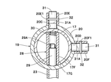
- the shaft body side stopper hole 17F coincides with the first arm side stopper hole 20C, as shown in FIG.
- the engaging pin 29 protrudes from the shaft body side stopper hole 17F by the urging force of the compression spring 30 and engages with the first arm side stopper hole 20C.
- the stopper 28 engages the engaging pin 29 with the first arm side stopper hole 20C by the compression spring 30 to stop the arm member 19 at a predetermined cab side storage position.
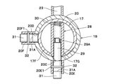
- the shaft body side stopper hole 17F coincides with the second arm side stopper hole 20D, as shown in FIG.
- the engaging pin 29 protrudes from the shaft body side stopper hole 17F by the urging force of the compression spring 30 and engages with the second arm side stopper hole 20D.
- the stopper 28 engages the engaging pin 29 with the second arm side stopper hole 20D by the compression spring 30 to stop the arm member 19 at a predetermined cab side storage position.
- the push pin 31 is movably provided on the inner peripheral side of the first collar 20E and the second collar 20F of the cylindrical portion 20, respectively.
- the push pin 31 is formed of, for example, a columnar shaft having an outer diameter equal to that of the engaging pin 29, and is slidably fitted to the inner peripheral side of the first collar 20E and the second collar 20F in the axial direction. is doing.
- a concave groove 31A is formed in the middle portion of the push pin 31 in the axial direction so as to have the outer peripheral surface of the push pin 31 notched toward the center of the axis.
- the retaining pin 32 is attached to the pin hole 20F1 of the second collar 20F. Therefore, the push pin 31 is retracted with respect to the first collar 20E and the second collar 20F by the concave groove 31A coming into contact with the retaining pin 32.
- the engaging pin 29 of the stopper 28 engages with the first arm side stopper hole 20C by the compression spring 30.
- the engaging pin 29 comes into contact with the push pin 31 and causes the push pin 31 to protrude from the first collar 20E.
- the recessed groove 31A of the push pin 31 comes into contact with the retaining pin 32, so that the push pin 31 is held in the first collar 20E.
- the operator pushes the push pin 31 protruding from the first collar 20E into the first collar 20E.
- the engaging pin 29 is pushed into the shaft body side stopper hole 17F against the compression spring 30, and is separated from the first arm side stopper hole 20C.
- the arm member 19 can be rotated with respect to the cable stand 16.
- the rotation control unit 33 is provided between the cable stand 16 and the arm member 19.
- the rotation control unit 33 regulates the arm member 19 from rotating toward the cab 6 beyond the cab side storage position or the cab rear storage position.
- the rotation restricting portion 33 includes an arm side protrusion 34 provided on the cylindrical portion 20 of the arm member 19, and a shaft body side protrusion 35 provided on the flange portion 17C of the stand body 17. Has been done.
- the arm-side protrusion 34 is fixed to the lower portion of the stay 23 on the outer peripheral surface of the cylindrical portion 20 by welding or the like.
- the arm-side protrusion 34 is formed as a plate body protruding downward from the lower end 20A of the cylindrical portion 20.
- a notch 34A that rotates along the outer peripheral surface of the flange portion 17C provided on the stand main body 17 is provided on the lower end side of the arm side protrusion 34.
- the shaft body side protrusion 35 is provided on the outer peripheral surface of the flange portion 17C. Specifically, the shaft body side protrusion 35 is integrally formed with the flange portion 17C as an arcuate protrusion portion in which the outer peripheral surface of the flange portion 17C is partially projected outward in the radial direction.
- the shaft body side protrusion 35 has a 90-degree arc shape centered on the shaft center AA of the cable stand 16, and the radius of the outer peripheral surface of the shaft body side protrusion 35 centered on the shaft center AA is the flange portion 17C. It is set larger than the radius of the outer peripheral surface of.
- the arm member 19 rotates with respect to the cable stand 16. Then, the notch 34A of the arm side protrusion 34 comes into contact with the shaft body side protrusion 35 provided on the flange portion 17C, so that the rotation of the arm member 19 is restricted.
- the notch portion 34A of the arm side protrusion 34 becomes one end 35A in the circumferential direction of the shaft body side protrusion 35.
- the arm member 19 rotates from the cab rear retracted position (position in FIG. 6) toward the cab 6, the notch 34A of the arm side protrusion 34 abuts on the other end 35B of the shaft body side protrusion 35 in the circumferential direction. Therefore, the arm member 19 does not rotate to the cab 6 side beyond the cab rear storage position, and does not rotate to the cab 6 side beyond the cab side storage position.
- the arm member 19 can rotate within the range of 270 degrees in the flange portion 17C where the shaft body side protrusion 35 is not provided.
- the electric hydraulic excavator 1 has the above-mentioned configuration, and the operation of the electric hydraulic excavator 1 will be described below.
- the power supply cable 13 extending from the external power supply is connected to the power supply port 12 of the electric hydraulic excavator 1.
- the electric power from the external power source is supplied to the electric motor 9 via the motor control device or the like (not shown), and the electric motor 9 drives the hydraulic pump 10 by the electric power from the external power source.
- the operator operates the traveling lever pedal (not shown) to drive the electric hydraulic excavator 1 to the work site.
- the operator operates a work operation lever (not shown) to rotate the upper swivel body 3 and excavate earth and sand by the work device 4. be able to.
- a part of the electric power (surplus electric power) from the external power source is charged in the battery 11.
- the intermediate portion of the power supply cable 13 connected to the power supply port 12 is supported by the cable support device 14.
- the arm member 19 is rotated around the axis AA of the cable stand 16 to the cable gripping position shown in FIG.
- the arm-side lock hole 20B of the cylindrical portion 20 coincides with the first shaft body-side lock hole 17D of the stand body 17.
- the lock pin 26 is inserted through the arm side lock hole 20B and the first shaft body side lock hole 17D.
- the ring pin 27 is inserted into the pin hole 26B on the tip end side of the lock pin 26 protruding from the outer peripheral surface of the cylindrical portion 20.
- the lock pin 26 is retracted in the axial direction, and the arm member 19 is fixed at the cable gripping position.
- the intermediate portion of the power feeding cable 13 is sandwiched between the clamp members 24A and 24B of the cable clamp 24 attached to the stay 23 of the arm member 19 and gripped, and the clamp members 24A and 24B are held in the closed position by the lock 24C. Fix it.
- the intermediate portion of the power feeding cable 13 is gripped by the tip of the stay 23 protruding rearward from the counterweight 7.
- the arm member 19 is prohibited from rotating with respect to the cable stand 16 by the lock mechanism 25 including the arm side lock hole 20B, the first shaft body side lock hole 17D, the lock pin 26, and the like, and is fixed at the cable gripping position. Therefore, regardless of the traveling operation of the electric hydraulic excavator 1 and the turning operation of the upper swing body 3, a sufficient distance can always be secured between the power feeding cable 13 and the electric hydraulic excavator 1.
- the power supply cable 13 from the external power source is removed from the power supply port 12.
- the clamp members 24A and 24B are moved to the open position by unlocking the lock 24C of the cable clamp 24.
- the power supply cable 13 can be easily released from the cable clamp 24, and the power supply cable 13 can be quickly removed from the cable support device 14.
- the arm member 19 of the cable support device 14 is fixed to the cab side storage position shown in FIG. 5 so as not to interfere with the turning operation of the upper turning body 3 and the operation of the working device 4. That is, by pulling out the lock pin 26 from the arm member 19 fixed to the cable gripping position, the arm member 19 is rotated 180 degrees counterclockwise with respect to the cable stand 16.
- the engaging pin 29 arranged in the shaft body side stopper hole 17F of the stand body 17 is provided with the inner peripheral surface of the cylindrical portion 20 by the compression spring 30. Is pressed against.
- the first arm side stopper hole 20C and the first collar 20E of the cylindrical portion 20 become the stand main body 17. It corresponds to the stopper hole 17F on the shaft body side of. Therefore, the engagement pin 29 protrudes from the shaft body side stopper hole 17F by the compression spring 30 and engages with the first arm side stopper hole 20C.
- the arm member 19 that rotates with respect to the cable stand 16 is retracted sideways to the cab by the stopper 28 including the shaft body side stopper hole 17F, the first arm side stopper hole 20C, the engagement pin 29, the compression spring 30, and the like. Automatically stop at the position.
- the push pin 31 arranged in the first collar 20E is pressed by the engagement pin 29 and protrudes from the first collar 20E.
- the concave groove 31A formed in the push pin 31 abuts on the retaining pin 32 attached to the first collar 20E.
- the movement of the push pin 31 is restricted, and the engaging pin 29 stops at the position where it engages with the first arm side stopper hole 20C, so that the arm member 19 can be held at the cab side storage position.
- the arm side lock hole 20B of the cylindrical portion 20 coincides with the first shaft body side lock hole 17D of the stand body 17.
- the lock pin 26 is inserted through the arm side lock hole 20B and the first shaft body side lock hole 17D, and the lock pin 26 is axially retracted by the ring pin 27.
- the arm member 19 is fixed to the cab side storage position, and when the electric hydraulic excavator 1 is operated by the electric power charged in the battery 11, the operation of the working device 4 is hindered by the cable support device 14. Can be prevented.
- the lock pin 26 is pulled out from the arm member 19 fixed to the cab side storage position.
- the push pin 31 protruding from the first collar 20E is pushed into the first collar 20E.
- the engaging pin 29 that comes into contact with the push pin 31 is pushed into the shaft body side stopper hole 17F against the compression spring 30, and is separated from the first arm side stopper hole 20C of the cylindrical portion 20.
- the arm member 19 can rotate with respect to the cable stand 16.
- the cable support device 14 is provided with a rotation restricting unit 33, and the rotation restricting unit 33 restricts the arm member 19 from rotating toward the cab 6 beyond the cab side storage position. That is, at a position where the arm member 19 is slightly rotated toward the cab 6 from the cab side storage position, the notch 34A of the arm side protrusion 34 abuts on one end 35A in the circumferential direction of the shaft body side protrusion 35. As a result, the arm member 19 is restricted from rotating toward the cab 6 beyond the cab side storage position, and the collision between the stay 23 and the cab 6 can be prevented.
- the arm member 19 is rotated 270 degrees clockwise with respect to the cable stand 16 in a state where the engaging pin 29 is separated from the stopper hole 20C on the first arm side of the cylindrical portion 20.
- the second arm side stopper hole 20D and the second collar 20F of the cylindrical portion 20 coincide with the shaft body side stopper hole 17F of the stand main body 17.
- the engagement pin 29 protrudes from the shaft body side stopper hole 17F by the compression spring 30 and engages with the second arm side stopper hole 20D. In this way, the arm member 19 is automatically stopped at the cab rear retracted position (position in FIG. 6) by the stopper 28.
- the push pin 31 arranged in the second collar 20F is pressed by the engagement pin 29, and the concave groove 31A abuts on the retaining pin 32 attached to the second collar 20F.
- the engaging pin 29 stops at the position where it engages with the first arm side stopper hole 20C, and the arm member 19 is held at the rear retracted position of the cab.
- the arm-side lock hole 20B of the cylindrical portion 20 coincides with the second axle body-side lock hole 17E of the stand body 17.
- the lock pin 26 is inserted through the arm side lock hole 20B and the second shaft body side lock hole 17E, and the lock pin 26 is axially retracted by the ring pin 27.
- the arm member 19 is fixed at the rear retracted position of the cab, and when the electric hydraulic excavator 1 is loaded on the transport vehicle, the arm member 19 can be prevented from inadvertently rotating and interfering with surrounding obstacles. .. As a result, the workability of the electric hydraulic excavator 1 during transportation can be improved.
- the lock pin 26 is transferred from the arm member 19 fixed to the cab rear storage position. Pull out.
- the engaging pin 29 is separated from the second arm side stopper hole 20D of the cylindrical portion 20.
- the arm member 19 can rotate with respect to the cable stand 16.
- the notch 34A of the arm side protrusion 34 abuts on the other end 35B of the shaft body side protrusion 35 in the circumferential direction. ..
- the arm member 19 is restricted from rotating toward the cab 6 beyond the rear storage position of the cab, and the collision between the stay 23 and the cab 6 can be prevented.
- the arm member 19 is rotated 90 degrees counterclockwise from the retracted position behind the cab, and when the arm member 19 reaches the cable gripping position, the arm-side lock hole 20B of the cylindrical portion 20 becomes the first axis of the stand body 17. It corresponds to the body side lock hole 17D.
- the lock pin 26 is inserted into the arm side lock hole 20B and the first shaft body side lock hole 17D, and the lock pin 26 is axially retracted by the ring pin 27, whereby the arm member 19 is connected to the cable. Fixed in the grip position
- the cable support device 14 in the electric hydraulic excavator 1 provided on the upper swivel body 3 and provided with the cable support device 14 for supporting the intermediate portion of the power supply cable 13, the cable support device 14 has the axis AA.
- a cable stand 16 attached to the upper swivel body 3 in a state of extending in the vertical direction, and an arm member 19 rotatably attached to the cable stand 16 around the axis AA and gripping the power feeding cable 13 on the tip side.
- a lock mechanism 25 that is detachably provided between the cable stand 16 and the arm member 19 and prohibits the rotation of the arm member 19 with respect to the cable stand 16 is included.
- the rotation of the arm member 19 with respect to the cable stand 16 attached to the upper swing body 3 is prohibited by the lock mechanism 25, and the arm member 19 can be fixed to the upper swing body 3.
- the power feeding cable 13 gripped by the arm member 19 can be prevented from coming into contact with a structure such as a cab 6 when the upper swivel body 3 is swiveled, and the power feeding cable 13 can be protected.
- the arm member 19 can be prevented from interfering with surrounding obstacles by prohibiting the rotation of the arm member 19 by the lock mechanism 25.
- the arm member 19 includes a cylindrical portion 20 rotatably fitted to the cable stand 16, and the lock mechanism 25 is provided on the cable stand 16 with a first axis penetrating the cable stand 16 in the radial direction.
- the body side lock hole 17D and the second shaft body side lock hole 17E are provided through the cylindrical portion 20 in the radial direction of the cylindrical portion 20, and the cylindrical portion 20 rotates with respect to the cable stand 16 to lock the first shaft body side.
- An arm-side lock hole 20B corresponding to the hole 17D or the second shaft body-side lock hole 17E, and a lock pin 26 inserted through the first shaft body-side lock hole 17D or the second shaft body-side lock hole 17E and the arm-side lock hole 20B. It is composed of.
- the arm member is simply inserted through the lock pin 26 through the lock hole 17D on the first shaft body side or the lock hole 17E on the second shaft body side of the cable stand 16 and the lock hole 20B on the arm side of the cylindrical portion 20.
- the rotation of 19 can be prohibited. Therefore, the workability can be improved as compared with the case where the rotation of the arm member is prohibited by using a dedicated jig, a tool, or the like.
- a stopper 28 is provided between the cable stand 16 and the arm member 19 to automatically stop the arm member 19 that rotates with respect to the cable stand 16 at a predetermined position.
- the arm member 19 is positioned by the stopper 28 at a position where the arm member 19 does not interfere with the cab 6. The rotation of 19 can be stopped.
- the arm member 19 includes a cylindrical portion 20 that rotatably fits into the cable stand 16, and the stopper 28 is a shaft body side stopper hole that opens on the outer peripheral surface of the cable stand 16 and extends in the radial direction of the cable stand 16.
- the first arm side stopper hole 20C and the second arm side stopper hole 20D which are provided in the cylindrical portion 20 and coincide with the shaft body side stopper hole 17F by rotating the cylindrical portion 20 with respect to the cable stand 16, and the shaft.
- the engaging pin 29 movably provided in the body side stopper hole 17F and the engaging pin 29 are urged in a direction protruding from the shaft body side stopper hole 17F, and the engaging pin 29 is placed on the first arm side stopper hole 20C or.
- the outer peripheral surface of the cylindrical portion 20 is provided with a cylindrical first collar 20E concentrically with the first arm side stopper hole 20C, and is concentrically cylindrical with the second arm side stopper hole 20D.
- a second collar 20F is provided, and an engaging pin 29 engaged with the first arm side stopper hole 20C or the second arm side stopper hole 20D is compressed on the inner peripheral side of the first collar 20E and the second collar 20F.
- a push pin 31 that pushes into the stopper hole 17F on the shaft body side against the spring 30 is provided. According to this configuration, the engaging pin 29 can be easily pushed from the first arm side stopper hole 20C or the second arm side stopper hole 20D by simply pushing the engaging pin 29 into the shaft body side stopper hole 17F by the push pin 31. It can be detached and the arm member 19 can be rotated with respect to the cable stand 16.
- the upper swing body 3 is provided with a cab 6 forming a driver's cab
- the arm member 19 has a cab side storage position arranged along the right side surface 6D of the cab 6 and a rear surface of the cab 6. It is fixed by the lock mechanism 25 to the cab rear storage position arranged along 6B.
- the arm member 19 is fixed to the cab side storage position, so that the arm member 19 operates the work device 4. It can be prevented from being disturbed.
- the electric hydraulic excavator 1 is loaded on the transport vehicle, by fixing the arm member 19 to the rear storage position of the cab, it is possible to prevent the arm member 19 from interfering with surrounding obstacles during transportation.
- a rotation restricting unit 33 for restricting the rotation of the arm member 19 to the cab 6 side beyond the cab side storage position or the cab rear storage position is provided between the cable stand 16 and the arm member 19.
- the arm member 19 fixed to the cab side storage position or the cab rear storage position is made rotatable, for example, even if the arm member 19 is fanned by a strong wind, the arm member 19 is cab 6 Rotation to the side can be regulated by the rotation regulating unit 33. This makes it possible to prevent the arm member 19 from colliding with the cab 6.
- a large-diameter disk-shaped flange portion 17C is provided in the middle portion of the cable stand 16 in the vertical direction, and the arm member 19 is rotatably fitted to the cable stand 16 and the lower end 20A is the flange portion.
- a cylindrical portion 20 that abuts on the 17C is provided, and the rotation restricting portion 33 projects downward from the cylindrical portion 20 and extends along the outer peripheral surface of the flange portion 17C to the arm side protrusion 34 and the outer peripheral surface of the flange portion 17C. It is configured to include a shaft body side protrusion 35 provided and to which the arm side protrusion 34 abuts.
- the arm side protrusion 34 comes into contact with the shaft body side protrusion 35 while rotating along the outer peripheral surface of the flange portion 17C.
- the rotation of the arm member 19 can be reliably regulated.
- a cable clamp 24 is provided on the tip end side of the arm member 19 to open and close between the closed position for gripping the power supply cable 13 and the open position for releasing the power supply cable 13.
- the power supply cable 13 can be easily gripped by sandwiching the power supply cable 13 with the cable clamp 24 in the closed position, and the work of supporting the power supply cable 13 by the cable support device 14 can be performed quickly. Can be done.
- the cable clamp 24 in the open position, the power supply cable 13 can be easily released, and the power supply cable 13 can be quickly removed from the cable support device 14.
- the battery 11 is mounted on the upper swing body 3, the electric motor 9 is driven by the electric power from the external power source, and the electric motor 9 is also driven by the electric power charged in the battery 11.
- the electric hydraulic excavator 1 is illustrated.
- the present invention is not limited to this, and can be applied to, for example, an electric construction machine in which a battery is not mounted and an electric motor is driven only by electric power from an external power source.
- two positions a cab rear storage position and a cab side storage position, are exemplified as positions where the rotation of the arm member 19 is automatically stopped by the stopper 28.
- the present invention is not limited to this, and for example, the rotation of the arm member 19 may be stopped by the stopper 28 at three positions including the cab rear storage position and the cab side storage position plus the cable gripping position.
- an arcuate shaft body side protrusion 35 integrally formed with the flange portion 17C of the stand body 17 is exemplified as the shaft body side protrusion constituting the rotation restricting portion 33.
- the present invention is not limited to this, and for example, two shaft body side protrusions corresponding to the cab rear storage position and the cab side storage position may be provided on the outer peripheral surface of the flange portion 17C.
Landscapes
- Engineering & Computer Science (AREA)
- Mining & Mineral Resources (AREA)
- Civil Engineering (AREA)
- General Engineering & Computer Science (AREA)
- Structural Engineering (AREA)
- Mechanical Engineering (AREA)
- Operation Control Of Excavators (AREA)
Priority Applications (4)
| Application Number | Priority Date | Filing Date | Title |
|---|---|---|---|
| CN202180017828.6A CN115190928A (zh) | 2020-09-11 | 2021-03-16 | 电动式工程机械 |
| EP21866278.1A EP4212673A4 (en) | 2020-09-11 | 2021-03-16 | Electric construction machine |
| US17/910,470 US11993918B2 (en) | 2020-09-11 | 2021-03-16 | Electric construction machine |
| JP2022547386A JP7320142B2 (ja) | 2020-09-11 | 2021-03-16 | 電動式建設機械 |
Applications Claiming Priority (2)
| Application Number | Priority Date | Filing Date | Title |
|---|---|---|---|
| JP2020152850 | 2020-09-11 | ||
| JP2020-152850 | 2020-09-11 |
Publications (1)
| Publication Number | Publication Date |
|---|---|
| WO2022054316A1 true WO2022054316A1 (ja) | 2022-03-17 |
Family
ID=80631497
Family Applications (1)
| Application Number | Title | Priority Date | Filing Date |
|---|---|---|---|
| PCT/JP2021/010650 Ceased WO2022054316A1 (ja) | 2020-09-11 | 2021-03-16 | 電動式建設機械 |
Country Status (5)
| Country | Link |
|---|---|
| US (1) | US11993918B2 (https=) |
| EP (1) | EP4212673A4 (https=) |
| JP (1) | JP7320142B2 (https=) |
| CN (1) | CN115190928A (https=) |
| WO (1) | WO2022054316A1 (https=) |
Citations (6)
| Publication number | Priority date | Publication date | Assignee | Title |
|---|---|---|---|---|
| JP2006232261A (ja) * | 2005-01-26 | 2006-09-07 | East Japan Railway Co | 柱上回転式作業装置 |
| US20090134599A1 (en) * | 2007-11-26 | 2009-05-28 | Agri-Fab, Inc. | Swivel Hitch and Method of Using Same |
| JP2010065445A (ja) | 2008-09-10 | 2010-03-25 | Hitachi Constr Mach Co Ltd | 電動式作業機械 |
| JP2011184007A (ja) * | 2010-03-11 | 2011-09-22 | Mitsubishi Agricultural Machinery Co Ltd | 作業用走行車の転倒保護フレーム |
| JP2017043980A (ja) * | 2015-08-27 | 2017-03-02 | 日立建機株式会社 | 電動式建設機械 |
| JP2018184783A (ja) * | 2017-04-26 | 2018-11-22 | 日立建機株式会社 | 電気駆動式作業機械のケーブルブラケット |
Family Cites Families (5)
| Publication number | Priority date | Publication date | Assignee | Title |
|---|---|---|---|---|
| US4587383A (en) * | 1983-06-27 | 1986-05-06 | Marathon Letourneau Company | Electrically powered mobile apparatus and method with suspended power cable |
| CN201818110U (zh) | 2010-10-19 | 2011-05-04 | 宁波市联勇鑫建筑五金有限公司 | 一种把手定位结构 |
| TWM407198U (en) * | 2011-02-16 | 2011-07-11 | Formosa Seiko Electronic Co Ltd | Motorcycle rotary foot pedals |
| CN107816069A (zh) | 2017-10-31 | 2018-03-20 | 株洲联诚集团控股股份有限公司 | 一种电动工程机械用受电撑杆 |
| CN209298799U (zh) * | 2018-12-21 | 2019-08-23 | 成都新一驱动科技有限责任公司 | 一种电动挖掘机电缆摆杆装置 |
-
2021
- 2021-03-16 US US17/910,470 patent/US11993918B2/en active Active
- 2021-03-16 JP JP2022547386A patent/JP7320142B2/ja active Active
- 2021-03-16 CN CN202180017828.6A patent/CN115190928A/zh active Pending
- 2021-03-16 WO PCT/JP2021/010650 patent/WO2022054316A1/ja not_active Ceased
- 2021-03-16 EP EP21866278.1A patent/EP4212673A4/en active Pending
Patent Citations (6)
| Publication number | Priority date | Publication date | Assignee | Title |
|---|---|---|---|---|
| JP2006232261A (ja) * | 2005-01-26 | 2006-09-07 | East Japan Railway Co | 柱上回転式作業装置 |
| US20090134599A1 (en) * | 2007-11-26 | 2009-05-28 | Agri-Fab, Inc. | Swivel Hitch and Method of Using Same |
| JP2010065445A (ja) | 2008-09-10 | 2010-03-25 | Hitachi Constr Mach Co Ltd | 電動式作業機械 |
| JP2011184007A (ja) * | 2010-03-11 | 2011-09-22 | Mitsubishi Agricultural Machinery Co Ltd | 作業用走行車の転倒保護フレーム |
| JP2017043980A (ja) * | 2015-08-27 | 2017-03-02 | 日立建機株式会社 | 電動式建設機械 |
| JP2018184783A (ja) * | 2017-04-26 | 2018-11-22 | 日立建機株式会社 | 電気駆動式作業機械のケーブルブラケット |
Non-Patent Citations (1)
| Title |
|---|
| See also references of EP4212673A4 |
Also Published As
| Publication number | Publication date |
|---|---|
| US11993918B2 (en) | 2024-05-28 |
| JP7320142B2 (ja) | 2023-08-02 |
| EP4212673A4 (en) | 2024-10-09 |
| CN115190928A (zh) | 2022-10-14 |
| US20230128121A1 (en) | 2023-04-27 |
| JPWO2022054316A1 (https=) | 2022-03-17 |
| EP4212673A1 (en) | 2023-07-19 |
Similar Documents
| Publication | Publication Date | Title |
|---|---|---|
| CN106917430B (zh) | 自推进的工作机器 | |
| US11904921B2 (en) | Handcart | |
| WO2005025968A1 (ja) | 建設機械 | |
| JP7715787B2 (ja) | 電動式建設機械 | |
| WO2010050469A1 (ja) | 建設機械用のキャブ | |
| JP2019189361A (ja) | バッテリ式フォークリフト | |
| JP2005324643A (ja) | バッテリストッパー | |
| WO2022054316A1 (ja) | 電動式建設機械 | |
| JP6975114B2 (ja) | 建設機械 | |
| WO2023074791A1 (ja) | 電動式建設機械 | |
| KR101981340B1 (ko) | 고소 작업차의 서브붐 장치 | |
| JP2021156127A (ja) | 作業機械 | |
| JP6648045B2 (ja) | 小型油圧ショベル | |
| JP7374030B2 (ja) | 建設機械 | |
| JP7237035B2 (ja) | 建設機械 | |
| JP2007118795A (ja) | 建設機械 | |
| JP7103898B2 (ja) | 作業用車両 | |
| JP2017141074A (ja) | 建設機械のプラットフォーム | |
| JP3900654B2 (ja) | フォークリフトのフード開閉機構 | |
| JP2019138005A (ja) | 作業車両 | |
| JP2001163268A (ja) | エンジン搭載機器の外装カバー装置 | |
| JP2025147920A (ja) | 作業機械 | |
| JP2008007965A (ja) | 建設機械 | |
| JP2022143383A (ja) | カム調整機構、カム調整方法、アウトリガ | |
| JP3162764B2 (ja) | クレーンのクラッチレバー装置 |
Legal Events
| Date | Code | Title | Description |
|---|---|---|---|
| 121 | Ep: the epo has been informed by wipo that ep was designated in this application |
Ref document number: 21866278 Country of ref document: EP Kind code of ref document: A1 |
|
| ENP | Entry into the national phase |
Ref document number: 2022547386 Country of ref document: JP Kind code of ref document: A |
|
| NENP | Non-entry into the national phase |
Ref country code: DE |
|
| ENP | Entry into the national phase |
Ref document number: 2021866278 Country of ref document: EP Effective date: 20230411 |