WO2022050367A1 - 二次電池及びその製造方法 - Google Patents
二次電池及びその製造方法 Download PDFInfo
- Publication number
- WO2022050367A1 WO2022050367A1 PCT/JP2021/032373 JP2021032373W WO2022050367A1 WO 2022050367 A1 WO2022050367 A1 WO 2022050367A1 JP 2021032373 W JP2021032373 W JP 2021032373W WO 2022050367 A1 WO2022050367 A1 WO 2022050367A1
- Authority
- WO
- WIPO (PCT)
- Prior art keywords
- negative electrode
- secondary battery
- electrode layer
- power generation
- porous
- Prior art date
- Legal status (The legal status is an assumption and is not a legal conclusion. Google has not performed a legal analysis and makes no representation as to the accuracy of the status listed.)
- Ceased
Links
Images


Classifications
-
- H—ELECTRICITY
- H01—ELECTRIC ELEMENTS
- H01M—PROCESSES OR MEANS, e.g. BATTERIES, FOR THE DIRECT CONVERSION OF CHEMICAL ENERGY INTO ELECTRICAL ENERGY
- H01M10/00—Secondary cells; Manufacture thereof
- H01M10/24—Alkaline accumulators
- H01M10/28—Construction or manufacture
-
- H—ELECTRICITY
- H01—ELECTRIC ELEMENTS
- H01M—PROCESSES OR MEANS, e.g. BATTERIES, FOR THE DIRECT CONVERSION OF CHEMICAL ENERGY INTO ELECTRICAL ENERGY
- H01M10/00—Secondary cells; Manufacture thereof
- H01M10/04—Construction or manufacture in general
-
- H—ELECTRICITY
- H01—ELECTRIC ELEMENTS
- H01M—PROCESSES OR MEANS, e.g. BATTERIES, FOR THE DIRECT CONVERSION OF CHEMICAL ENERGY INTO ELECTRICAL ENERGY
- H01M10/00—Secondary cells; Manufacture thereof
- H01M10/24—Alkaline accumulators
- H01M10/30—Nickel accumulators
-
- H—ELECTRICITY
- H01—ELECTRIC ELEMENTS
- H01M—PROCESSES OR MEANS, e.g. BATTERIES, FOR THE DIRECT CONVERSION OF CHEMICAL ENERGY INTO ELECTRICAL ENERGY
- H01M10/00—Secondary cells; Manufacture thereof
- H01M10/24—Alkaline accumulators
- H01M10/32—Silver accumulators
-
- H—ELECTRICITY
- H01—ELECTRIC ELEMENTS
- H01M—PROCESSES OR MEANS, e.g. BATTERIES, FOR THE DIRECT CONVERSION OF CHEMICAL ENERGY INTO ELECTRICAL ENERGY
- H01M12/00—Hybrid cells; Manufacture thereof
- H01M12/08—Hybrid cells; Manufacture thereof composed of a half-cell of a fuel-cell type and a half-cell of the secondary-cell type
-
- H—ELECTRICITY
- H01—ELECTRIC ELEMENTS
- H01M—PROCESSES OR MEANS, e.g. BATTERIES, FOR THE DIRECT CONVERSION OF CHEMICAL ENERGY INTO ELECTRICAL ENERGY
- H01M4/00—Electrodes
- H01M4/02—Electrodes composed of, or comprising, active material
- H01M4/24—Electrodes for alkaline accumulators
-
- H—ELECTRICITY
- H01—ELECTRIC ELEMENTS
- H01M—PROCESSES OR MEANS, e.g. BATTERIES, FOR THE DIRECT CONVERSION OF CHEMICAL ENERGY INTO ELECTRICAL ENERGY
- H01M4/00—Electrodes
- H01M4/02—Electrodes composed of, or comprising, active material
- H01M4/24—Electrodes for alkaline accumulators
- H01M4/244—Zinc electrodes
-
- H—ELECTRICITY
- H01—ELECTRIC ELEMENTS
- H01M—PROCESSES OR MEANS, e.g. BATTERIES, FOR THE DIRECT CONVERSION OF CHEMICAL ENERGY INTO ELECTRICAL ENERGY
- H01M4/00—Electrodes
- H01M4/02—Electrodes composed of, or comprising, active material
- H01M4/36—Selection of substances as active materials, active masses, active liquids
- H01M4/38—Selection of substances as active materials, active masses, active liquids of elements or alloys
-
- H—ELECTRICITY
- H01—ELECTRIC ELEMENTS
- H01M—PROCESSES OR MEANS, e.g. BATTERIES, FOR THE DIRECT CONVERSION OF CHEMICAL ENERGY INTO ELECTRICAL ENERGY
- H01M50/00—Constructional details or processes of manufacture of the non-active parts of electrochemical cells other than fuel cells, e.g. hybrid cells
- H01M50/40—Separators; Membranes; Diaphragms; Spacing elements inside cells
- H01M50/403—Manufacturing processes of separators, membranes or diaphragms
-
- H—ELECTRICITY
- H01—ELECTRIC ELEMENTS
- H01M—PROCESSES OR MEANS, e.g. BATTERIES, FOR THE DIRECT CONVERSION OF CHEMICAL ENERGY INTO ELECTRICAL ENERGY
- H01M50/00—Constructional details or processes of manufacture of the non-active parts of electrochemical cells other than fuel cells, e.g. hybrid cells
- H01M50/40—Separators; Membranes; Diaphragms; Spacing elements inside cells
- H01M50/46—Separators, membranes or diaphragms characterised by their combination with electrodes
-
- H—ELECTRICITY
- H01—ELECTRIC ELEMENTS
- H01M—PROCESSES OR MEANS, e.g. BATTERIES, FOR THE DIRECT CONVERSION OF CHEMICAL ENERGY INTO ELECTRICAL ENERGY
- H01M50/00—Constructional details or processes of manufacture of the non-active parts of electrochemical cells other than fuel cells, e.g. hybrid cells
- H01M50/40—Separators; Membranes; Diaphragms; Spacing elements inside cells
- H01M50/463—Separators, membranes or diaphragms characterised by their shape
-
- H—ELECTRICITY
- H01—ELECTRIC ELEMENTS
- H01M—PROCESSES OR MEANS, e.g. BATTERIES, FOR THE DIRECT CONVERSION OF CHEMICAL ENERGY INTO ELECTRICAL ENERGY
- H01M50/00—Constructional details or processes of manufacture of the non-active parts of electrochemical cells other than fuel cells, e.g. hybrid cells
- H01M50/40—Separators; Membranes; Diaphragms; Spacing elements inside cells
- H01M50/471—Spacing elements inside cells other than separators, membranes or diaphragms; Manufacturing processes thereof
- H01M50/474—Spacing elements inside cells other than separators, membranes or diaphragms; Manufacturing processes thereof characterised by their position inside the cells
-
- H—ELECTRICITY
- H01—ELECTRIC ELEMENTS
- H01M—PROCESSES OR MEANS, e.g. BATTERIES, FOR THE DIRECT CONVERSION OF CHEMICAL ENERGY INTO ELECTRICAL ENERGY
- H01M50/00—Constructional details or processes of manufacture of the non-active parts of electrochemical cells other than fuel cells, e.g. hybrid cells
- H01M50/40—Separators; Membranes; Diaphragms; Spacing elements inside cells
- H01M50/471—Spacing elements inside cells other than separators, membranes or diaphragms; Manufacturing processes thereof
- H01M50/477—Spacing elements inside cells other than separators, membranes or diaphragms; Manufacturing processes thereof characterised by their shape
-
- H—ELECTRICITY
- H01—ELECTRIC ELEMENTS
- H01M—PROCESSES OR MEANS, e.g. BATTERIES, FOR THE DIRECT CONVERSION OF CHEMICAL ENERGY INTO ELECTRICAL ENERGY
- H01M50/00—Constructional details or processes of manufacture of the non-active parts of electrochemical cells other than fuel cells, e.g. hybrid cells
- H01M50/40—Separators; Membranes; Diaphragms; Spacing elements inside cells
- H01M50/471—Spacing elements inside cells other than separators, membranes or diaphragms; Manufacturing processes thereof
- H01M50/48—Spacing elements inside cells other than separators, membranes or diaphragms; Manufacturing processes thereof characterised by the material
- H01M50/486—Organic material
-
- H—ELECTRICITY
- H01—ELECTRIC ELEMENTS
- H01M—PROCESSES OR MEANS, e.g. BATTERIES, FOR THE DIRECT CONVERSION OF CHEMICAL ENERGY INTO ELECTRICAL ENERGY
- H01M50/00—Constructional details or processes of manufacture of the non-active parts of electrochemical cells other than fuel cells, e.g. hybrid cells
- H01M50/40—Separators; Membranes; Diaphragms; Spacing elements inside cells
- H01M50/489—Separators, membranes, diaphragms or spacing elements inside the cells, characterised by their physical properties, e.g. swelling degree, hydrophilicity or shut down properties
-
- H—ELECTRICITY
- H01—ELECTRIC ELEMENTS
- H01M—PROCESSES OR MEANS, e.g. BATTERIES, FOR THE DIRECT CONVERSION OF CHEMICAL ENERGY INTO ELECTRICAL ENERGY
- H01M4/00—Electrodes
- H01M4/02—Electrodes composed of, or comprising, active material
- H01M2004/021—Physical characteristics, e.g. porosity, surface area
-
- H—ELECTRICITY
- H01—ELECTRIC ELEMENTS
- H01M—PROCESSES OR MEANS, e.g. BATTERIES, FOR THE DIRECT CONVERSION OF CHEMICAL ENERGY INTO ELECTRICAL ENERGY
- H01M4/00—Electrodes
- H01M4/02—Electrodes composed of, or comprising, active material
- H01M2004/026—Electrodes composed of, or comprising, active material characterised by the polarity
- H01M2004/027—Negative electrodes
-
- Y—GENERAL TAGGING OF NEW TECHNOLOGICAL DEVELOPMENTS; GENERAL TAGGING OF CROSS-SECTIONAL TECHNOLOGIES SPANNING OVER SEVERAL SECTIONS OF THE IPC; TECHNICAL SUBJECTS COVERED BY FORMER USPC CROSS-REFERENCE ART COLLECTIONS [XRACs] AND DIGESTS
- Y02—TECHNOLOGIES OR APPLICATIONS FOR MITIGATION OR ADAPTATION AGAINST CLIMATE CHANGE
- Y02E—REDUCTION OF GREENHOUSE GAS [GHG] EMISSIONS, RELATED TO ENERGY GENERATION, TRANSMISSION OR DISTRIBUTION
- Y02E60/00—Enabling technologies; Technologies with a potential or indirect contribution to GHG emissions mitigation
- Y02E60/10—Energy storage using batteries
-
- Y—GENERAL TAGGING OF NEW TECHNOLOGICAL DEVELOPMENTS; GENERAL TAGGING OF CROSS-SECTIONAL TECHNOLOGIES SPANNING OVER SEVERAL SECTIONS OF THE IPC; TECHNICAL SUBJECTS COVERED BY FORMER USPC CROSS-REFERENCE ART COLLECTIONS [XRACs] AND DIGESTS
- Y02—TECHNOLOGIES OR APPLICATIONS FOR MITIGATION OR ADAPTATION AGAINST CLIMATE CHANGE
- Y02P—CLIMATE CHANGE MITIGATION TECHNOLOGIES IN THE PRODUCTION OR PROCESSING OF GOODS
- Y02P70/00—Climate change mitigation technologies in the production process for final industrial or consumer products
- Y02P70/50—Manufacturing or production processes characterised by the final manufactured product
Definitions
- the present invention relates to a secondary battery, particularly a secondary battery having a dissolution-precipitation type electrode in which dissolution and precipitation of an electrode active material are repeated with charge and discharge, and a method for manufacturing the same.
- the negative electrode shape changes to an undesired shape and size due to repeated charging and discharging.
- the problem of negative electrode shape change is known. For example, in the case of a zinc secondary battery, as shown in FIG. 7, as the negative electrode layer 14 is repeatedly charged and discharged, it shrinks unevenly from the end to the center, that is, the outer peripheral portion of the negative electrode layer 14 is non-existent. There is a phenomenon that it is uniformly eroded and lost.
- the negative electrode active material 14a (ZnO) constituting the negative electrode layer 14 moves from the end portion of the battery toward the center through repeated dissolution and precipitation associated with charging and discharging. That is, the negative electrode layer 14 is gently deformed toward the center due to the diffusion of zinc oxide ions due to the dissolution of ZnO.
- Such a shape change of the negative electrode layer 14 leads to a decrease in the effective region of the negative electrode layer 14 facing the positive electrode layer 12, and as a result, the battery resistance is increased, the battery capacity is decreased, and the life of the secondary battery is shortened.
- Patent Document 1 Japanese Unexamined Patent Publication No. 2019-106351
- Patent Document 2 Japanese Unexamined Patent Publication No. 2020-38763
- the negative electrode contains a Zn compound which is a composite metal oxide of Zn and at least one selected from the group consisting of Al, In, Ti and Nb.
- Zinc secondary batteries are disclosed.
- Patent Document 3 (WO2020 / 049902) describes one selected from (A) ZnO particles, (B) (i) metal Zn particles having an average particle size D50 of 5 to 80 ⁇ m, and (ii) In and Bi.
- a zinc secondary battery comprising a negative electrode containing the above metal elements and at least two selected from a binder resin having a (iii) hydroxyl group is disclosed.
- the present inventors have recently found that the shape change of the negative electrode can be effectively suppressed at low cost only by partitioning a plurality of power generation regions in a linear non-power generation region so as to satisfy a predetermined condition. Obtained.
- an object of the present invention is to provide a secondary battery capable of effectively suppressing the shape change of the negative electrode due to repeated charging and discharging at low cost.
- the secondary battery has a dissolution-precipitation type electrode in which dissolution and precipitation of the electrode active material are repeated with charge and discharge, and the secondary battery has a power generation unit.
- the power generation unit is A positive electrode layer containing a positive electrode active material and a positive electrode current collector supporting the positive electrode active material, and A negative electrode layer containing a negative electrode active material and a negative electrode current collector supporting the negative electrode active material, and A porous separator interposed between the positive electrode layer and the negative electrode layer, An electrolytic solution impregnated with the positive electrode layer, the negative electrode layer and the porous separator, The negative electrode layer is the dissolution-precipitation type electrode.
- a secondary battery is provided in which the value ⁇ defined by the thickness (mm) of the quality separator is 30 or less.
- a method for manufacturing the secondary battery there is a method for manufacturing the secondary battery.
- a method for manufacturing a secondary battery including the above is provided.
- FIG. 3 is a cross-sectional view taken along the line AA of the secondary battery shown in FIG. It is a figure which conceptually explains the shape change suppression of the negative electrode in the secondary battery which the ⁇ value is 30 or less by this invention. It is a figure which conceptually explains the shape change progress of the negative electrode in the secondary battery which the ⁇ value exceeds 30. It is sectional drawing which conceptually shows an example of the secondary battery according to this invention provided with a resin spacer. It is sectional drawing which conceptually shows an example of the secondary battery by this invention which provided with the negative electrode spacer. It is a figure which conceptually explains the shape change progress of the negative electrode in a conventional secondary battery.
- the secondary battery according to the present invention has a dissolution-precipitation type electrode in which the electrode active material is repeatedly dissolved and deposited as the electrode is charged and discharged.
- a typical example of the dissolution-precipitation type electrode is a zinc negative electrode used in a zinc secondary battery.
- the zinc secondary battery include a nickel zinc secondary battery, a silver zinc oxide secondary battery, a manganese zinc oxide secondary battery, and a zinc air secondary battery. Therefore, in the following description, the zinc secondary battery will be described as appropriate.
- FIGS 1 and 2 show a conceptual diagram of such a secondary battery.
- the secondary battery has a power generation unit 10.
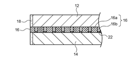
- the power generation unit 10 includes a positive electrode layer 12, a negative electrode layer 14, a porous separator 16, and an electrolytic solution 18.
- the positive electrode layer 12 includes a positive electrode active material 12a and a positive electrode current collector 12b that supports the positive electrode active material 12a.
- the negative electrode layer 14 includes a negative electrode active material 14a and a negative electrode current collector 14b supporting the negative electrode active material 14a.
- the porous separator is interposed between the positive electrode layer 12 and the negative electrode layer 14.
- the positive electrode layer 12, the negative electrode layer 14, and the porous separator 16 are impregnated with the electrolytic solution 18.
- the negative electrode layer 14 is a dissolution-precipitation type electrode.
- the functional region 20 specified as the region where the positive electrode layer 12, the negative electrode layer 14, the electrolytic solution 18, and the porous separator 16 overlap is a plurality of power generation regions 20a.
- the power generation region 20a and the non-power generation region 20b are defined by the porous portion 16a and the dense portion 16b of the porous separator 16, respectively, but masking or a similar method (for example, a paste is applied to the porous portion 16a).
- the power generation region 20a and the non-power generation region 20b may be partitioned by other methods such as filling to obtain the non-power generation region 20b).
- the value ⁇ defined by the thickness (mm) of 16 is 30 or less.
- the negative electrode active material 14a By suppressing the shape change, the negative electrode active material 14a can be used efficiently. Therefore, the N / P ratio (the ratio of the capacity of the negative electrode active material to the capacity of the positive electrode active material) can be lowered, and as a result, a compact battery can be constructed.
- the negative electrode layer 14 shrinks unevenly from the end to the center as the negative electrode layer 14 repeats charging and discharging, that is, the outer peripheral portion of the negative electrode layer 14. Is unevenly eroded and lost. This is because the negative electrode active material 14a (for example, ZnO) constituting the negative electrode layer 14 moves from the end portion of the electrode toward the center through repeated dissolution and precipitation associated with charging and discharging. That is, the negative electrode layer 14 is gently deformed toward the center due to the diffusion of zinc oxide ions due to the dissolution of ZnO.
- the negative electrode active material 14a for example, ZnO
- a plurality of power generation regions 20a are partitioned by linear non-power generation regions 20b.
- the negative electrode active material 14a is repeatedly dissolved and deposited and deformed with charge and discharge, while the non-power generation region 20b is not or hardly involved in charge and discharge. Dissolution and precipitation of 14a are significantly suppressed.
- the negative electrode active material 14a which is deposited in each power generation region 20a due to charge / discharge and tends to cause a shape change, is dammed in the non-power generation region 20b.
- the shape change suppressing effect is inferior.
- the area circle equivalent diameter ⁇ per power generation region 20a is relatively wide, so that the left side ( ⁇ P) reflecting the shape changing force is reflected. ) Can be seen to overcome the right side (30 wt), which reflects the resistance to shape change.
- a large amount of the negative electrode active material 14a deposited due to charging / discharging in each power generation region 20a cannot be dammed in the non-power generation region 20b, and the negative electrode layer 14 cannot be dammed from the end to the inside. Allows the shape change to proceed.
- ⁇ is 30 or less, preferably 28 or less, more preferably 26 or less, and further preferably 24 or less.
- the lower limit of the value ⁇ is not particularly limited, but is typically 5 or more, and more typically 10 or more.
- the area circle equivalent diameter ⁇ per power generation region 20a is preferably 6.0 mm or less, more preferably 5.0 mm or less, further preferably 4.0 mm or less, particularly preferably 3.0 mm or less, and most preferably 2.0 mm. It is as follows.
- the area equivalent circle diameter is defined as the diameter of a circle having an area equal to the projected area per power generation area 20a, following the definition of JIS Z8827-1.
- the thickness P of the negative electrode layer 14 is preferably 0.1 to 1.0 mm, more preferably 0.2 to 0.9 mm, still more preferably 0.3 to 0.8 mm, and particularly preferably 0.4 to 0. It is 7 mm.
- the line width w of the non-power generation region 20b is preferably 0.01 to 1.0 mm, more preferably 0.1 to 0.9 mm, still more preferably 0.2 to 0.8 mm, and particularly preferably 0.3 to 0. It is 0.7 mm.
- the thickness t of the porous separator 16 is preferably 0.02 to 0.5 mm, more preferably 0.03 to 0.4 mm, still more preferably 0.04 to 0.3 mm, and particularly preferably 0.05 to 0. It is .2 mm.
- the thickness of the porous separator 16 may differ between the porous portion 16a and the dense portion 16b, but in that case, the thickness of the thicker portion (typically the porous portion 16a) is set to the thickness of the porous portion 16a. It may be adopted as a thickness t of 16.
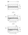
- a spacer for example, a resin spacer or a negative electrode spacer
- a spacer 22 or 22' is provided between the negative electrode layer 14 and the dense portion 16b so as to fill the gap.
- the spacer 22 according to the preferred embodiment shown in FIG. 5 contains a resin. That is, by providing the resin spacer 22 at a position corresponding to the dense portion 16b, the gap between the negative electrode layer 14 and the dense portion 16b can be filled. By doing so, the diffusion of zincate ions can be suppressed more effectively as compared with the case where the spacer 22 is not provided, so that a more excellent shape change suppressing effect can be realized.
- the spacer 22' according to another preferred embodiment shown in FIG. 6 contains a negative electrode active material and / or a negative electrode current collector, thereby forming a convex portion 14c (hereinafter, also referred to as a negative electrode spacer 22') of the negative electrode layer 14. ing. That is, by forming the convex portion 14c containing the negative electrode active material and / or the negative electrode current collector at the position corresponding to the dense portion 16b on the surface of the negative electrode layer 14, the gap between the negative electrode layer 14 and the dense portion 16b is formed. Can be filled.
- the thickness t 1 (mm) of the convex portion 14c that is, the negative electrode spacer 22'
- the thickness t (mm) of the porous separator satisfy the relationship of t 1 / t ⁇ 0.5. It is preferable in that the diffusion of acid ions can be suppressed more effectively, and a more excellent shape change suppressing effect can be realized.
- the power generation area 20a and the non-power generation area 20b form a regular pattern.
- the power generation region 20a can be uniformly provided over the entire functional region 20, so that the shape change of the negative electrode can be suppressed more effectively.
- preferred regular patterns include, for example, the individual shapes of the power generation region 20a are squares, rectangles, rhombuses, triangles, other polygons, circles, etc., but are preferably squares or rhombuses.
- the porous separator 16 can be a separator generally used in various secondary batteries.
- Preferred porous separators 16 are porous membranes and / or non-woven fabrics. It is more preferable that the porous film and the non-woven fabric are made of resin in that a dense portion can be formed more efficiently than a hot press.
- the LDH separator for preventing zinc dendrite penetration in a zinc secondary battery as disclosed in Patent Documents 1 to 3 is a dense separator in which a porous substrate is filled with a layered double hydroxide (LDH). And therefore should be distinguished from porous separators.
- LDH layered double hydroxide
- the secondary battery is a zinc secondary battery
- the porous separator 16 is partitioned into a porous portion 16a and a dense portion 16b, the porous portion 16a defines a power generation region 20a, and the dense portion 16b defines a non-power generation region 20b. That is, it is preferable that the porous separator 16 is provided with the dense portion 16b, and the non-power generation region 20b is formed due to the denseness thereof. That is, since the function of the porous separator 16 is canceled by the denseness of the dense portion 16b, the dense portion 16b is not or hardly involved in charging / discharging, resulting in a non-power generation region 20b.
- the shape of the negative electrode can be changed only by using the porous separator 16 partitioned into the porous portion 16a and the dense portion 16b without separately requiring a special member for forming the non-power generation region 20b. Can be suppressed.
- the density of the dense portion 16b is 1.1 times or more, preferably 1.3 times or more, more preferably 1.5 times or more, still more preferably 1.8 times or more, and particularly preferably 1.8 times or more the density of the porous portion 16a. It is 2.0 times or more. The higher the density of the dense portion 16b, the better, so that the upper limit thereof is not particularly limited.
- the positive electrode layer 12 includes a positive electrode active material 12a and a positive electrode current collector 12b that supports the positive electrode active material 12a.
- a positive electrode active material 12a and the positive electrode current collector 12b appropriate materials may be selected according to the type of the secondary battery.
- the positive electrode active material 12a is preferably nickel hydroxide and / or nickel oxyhydroxide
- the positive electrode current collector 12b is preferably a nickel porous substrate such as a foamed nickel plate.
- the negative electrode layer 14 includes a negative electrode active material 14a and a negative electrode current collector 14b that supports the negative electrode active material 14a.
- the positive electrode active material 12a and the positive electrode current collector 12b appropriate materials may be selected according to the type of the secondary battery.
- the negative electrode active material 14a preferably contains a zinc material.
- the zinc material may be contained in any form of zinc metal, zinc compound and zinc alloy as long as it has an electrochemical activity suitable for the negative electrode.
- Preferred examples of the zinc material include zinc oxide, zinc metal, calcium zincate and the like, but a mixture of zinc metal and zinc oxide is more preferable.
- the electrolytic solution 18 may be an electrolytic solution 18 suitable for a secondary battery.
- the electrolytic solution 18 preferably contains an aqueous alkali metal hydroxide solution.
- the alkali metal hydroxide include potassium hydroxide, sodium hydroxide, lithium hydroxide, ammonium hydroxide and the like, but potassium hydroxide is more preferable.
- Zinc oxide, zinc hydroxide and the like may be added to the electrolytic solution in order to suppress autolysis of the zinc-containing material.
- the porous separator 16 is processed and partitioned into the porous portion 16a and the dense portion 16b, and (ii) the partitioned porous separator 16 and the positive electrode layer 12 are formed. This can be done by assembling a secondary battery using the negative electrode layer 14 and the electrolytic solution 18.
- Porous Separator 16 is processed to define a porous portion 16a that defines a plurality of power generation regions 20a and a linear non-power generation region 20b that defines each of the plurality of power generation regions 20a. It is partitioned into a dense portion 16b.
- the processing of the porous separator 16 is not particularly limited as long as the dense portion 16b has a predetermined density (for example, 1.1 times or more the porous portion 16a), but the porous separator 16 is air-pressed to be dense. It is preferable to form the portion 16b in terms of low cost and excellent mass productivity.
- the dense portion 16b can be easily and efficiently formed by pressing a predetermined patterned mold (projection) against the porous separator 16 and compressing it.
- the pattern of the mold (toppan) is preferably a regular pattern as described above. It is also preferable to heat the mold (toppan) when pressing it. By doing so, the density of the dense portion 16b can be further increased.
- the porous separator 16 is preferably made of resin.
- the secondary battery is assembled using the porous separator 16, the positive electrode layer 12, the negative electrode layer 14, and the electrolytic solution 18 partitioned as described above. This assembly may be performed according to a known method and is not particularly limited.
- the gap between the negative electrode layer 14 and the dense portion 16b can be filled on the surface of the negative electrode layer 14 and / or the surface of the dense portion 16b after the secondary battery is assembled.
- a spacer may be formed.
- the method for forming the spacer is not particularly limited, but when the resin spacer 22 as shown in FIG. 5 is formed, the resin paste is printed on the partitioned porous separator 16 obtained in the above step (i), or the above.
- the resin spacer 22 can be preferably formed by printing a resin paste on the negative electrode layer 14 or the like before the step (ii). Preferred examples of the printing method include screen printing, gravure printing and the like.
- the negative electrode spacer 22'as shown in FIG. 6 is formed, the negative electrode layer 14 is embossed or the like before the step (ii) to form irregularities on the surface thereof, thereby forming the negative electrode spacer 22. 'Can be preferably formed.
- the shape change of the negative electrode can be effectively suppressed only by subjecting the porous separator 16 to simple processing (for example, blank pressing), so that mass production or manufacturing can be performed. It can be said that it is extremely advantageous from the viewpoint of cost.
- Example 1 (comparison) (1) Preparation of Nickel-Zinc Secondary Battery A positive electrode layer, a negative electrode layer, a porous separator, and an electrolytic solution having the specifications shown below were prepared.
- -Positive electrode layer A positive electrode active material slurry containing nickel hydroxide particles filled in the pores of expanded nickel (positive electrode current collector) (size: 200 mm square, thickness: 0.5 mm).
- Negative electrode active material paste containing metallic zinc powder and zinc oxide powder is pressure-bonded to copper expanded metal (negative electrode current collector) (size: 200 mm square, thickness: 0.5 mm (thickness of negative electrode current collector) Including))
- -Porous separator Polypropylene non-woven fabric (thickness: 100 ⁇ m, basis weight: 40 g / m 2 )
- -Electrolyte 5.4 mol / L KOH aqueous solution in which 0.4 mol / L ZnO is dissolved
- the negative electrode layer was wrapped in a porous separator and housed in a battery container while facing the positive electrode layer.
- An electrolytic solution was injected into the battery container to obtain a nickel-zinc secondary battery.
- Examples 2-10 The porous separator was blank-pressed to form a dense portion so that a plurality of porous portions were partitioned into regular patterns of various shapes and dimensions shown in Table 1, and each of the porous separator and the negative electrode layer.
- a nickel-zinc secondary battery was prepared and evaluated in the same manner as in Example 1 except that the thickness was as shown in Table 1.
- a regular pattern pattern toppan is pressed against the porous separator before it is combined with the negative electrode layer, and the area to be a dense area (corresponding to the non-power generation area) is compressed while being heated. went.
- Examples 11-13 Nickel-zinc secondary batteries were prepared and evaluated in the same manner as in Examples 2 to 4, except that the resin spacers were formed and the thicknesses of the porous separator and the negative electrode layer were as shown in Table 2. rice field.
- the resin spacer was formed by screen-printing a resin paste on the surface of the dense portion of the porous separator.
- Examples 14-19 Except that the negative electrode spacer (convex portion of the negative electrode) was formed so as to have the t 1 / t ratio shown in Table 2, and the thicknesses of the porous separator and the negative electrode layer were set as shown in Table 2.
- Nickel-zinc secondary batteries were prepared and evaluated in the same manner as in Examples 2 to 4.
- the resin spacer is formed by embossing the surface of the negative electrode layer so that the gap between the negative electrode layer and the dense portion can be filled after assembly, and a predetermined t is formed on the portion facing the dense portion. This was done by forming a 1 / t ratio negative electrode convex portion.
- the functional area is divided into a plurality of power generation areas and a linear non-power generation area defining each of the plurality of power generation areas, and the value of the parameter ⁇ is 30.
- Examples 2, 4, 5 and 8 below compared with Example 1 having no non-power generation region and Examples 3, 6, 7, 9 and 10 having a non-power generation region but having an ⁇ value of more than 30.
- the residual area ratio of the negative electrode layer was high (that is, the negative electrode shape change was small), and the cycle life was long.
Landscapes
- Chemical & Material Sciences (AREA)
- Chemical Kinetics & Catalysis (AREA)
- Electrochemistry (AREA)
- General Chemical & Material Sciences (AREA)
- Engineering & Computer Science (AREA)
- Manufacturing & Machinery (AREA)
- Battery Electrode And Active Subsutance (AREA)
- Cell Separators (AREA)
Priority Applications (2)
| Application Number | Priority Date | Filing Date | Title |
|---|---|---|---|
| JP2022546976A JPWO2022050367A1 (https=) | 2020-09-04 | 2021-09-02 | |
| US18/161,933 US20230170534A1 (en) | 2020-09-04 | 2023-01-31 | Secondary battery and manufacturing method therefor |
Applications Claiming Priority (2)
| Application Number | Priority Date | Filing Date | Title |
|---|---|---|---|
| JP2020-149465 | 2020-09-04 | ||
| JP2020149465 | 2020-09-04 |
Related Child Applications (1)
| Application Number | Title | Priority Date | Filing Date |
|---|---|---|---|
| US18/161,933 Continuation US20230170534A1 (en) | 2020-09-04 | 2023-01-31 | Secondary battery and manufacturing method therefor |
Publications (1)
| Publication Number | Publication Date |
|---|---|
| WO2022050367A1 true WO2022050367A1 (ja) | 2022-03-10 |
Family
ID=80491071
Family Applications (1)
| Application Number | Title | Priority Date | Filing Date |
|---|---|---|---|
| PCT/JP2021/032373 Ceased WO2022050367A1 (ja) | 2020-09-04 | 2021-09-02 | 二次電池及びその製造方法 |
Country Status (3)
| Country | Link |
|---|---|
| US (1) | US20230170534A1 (https=) |
| JP (1) | JPWO2022050367A1 (https=) |
| WO (1) | WO2022050367A1 (https=) |
Citations (4)
| Publication number | Priority date | Publication date | Assignee | Title |
|---|---|---|---|---|
| JPH04206468A (ja) * | 1990-11-30 | 1992-07-28 | Yuasa Corp | 密閉型アルカリ亜鉛蓄電池 |
| JP2004146238A (ja) * | 2002-10-25 | 2004-05-20 | Matsushita Electric Ind Co Ltd | 電池用セパレータ及び電池 |
| JP2009516325A (ja) * | 2005-09-16 | 2009-04-16 | スプ カン,ボン | 区画された電解質を有するリチウム2次電池 |
| JP2014192137A (ja) * | 2013-03-28 | 2014-10-06 | Mitsubishi Heavy Ind Ltd | 二次電池 |
-
2021
- 2021-09-02 WO PCT/JP2021/032373 patent/WO2022050367A1/ja not_active Ceased
- 2021-09-02 JP JP2022546976A patent/JPWO2022050367A1/ja active Pending
-
2023
- 2023-01-31 US US18/161,933 patent/US20230170534A1/en active Pending
Patent Citations (4)
| Publication number | Priority date | Publication date | Assignee | Title |
|---|---|---|---|---|
| JPH04206468A (ja) * | 1990-11-30 | 1992-07-28 | Yuasa Corp | 密閉型アルカリ亜鉛蓄電池 |
| JP2004146238A (ja) * | 2002-10-25 | 2004-05-20 | Matsushita Electric Ind Co Ltd | 電池用セパレータ及び電池 |
| JP2009516325A (ja) * | 2005-09-16 | 2009-04-16 | スプ カン,ボン | 区画された電解質を有するリチウム2次電池 |
| JP2014192137A (ja) * | 2013-03-28 | 2014-10-06 | Mitsubishi Heavy Ind Ltd | 二次電池 |
Also Published As
| Publication number | Publication date |
|---|---|
| JPWO2022050367A1 (https=) | 2022-03-10 |
| US20230170534A1 (en) | 2023-06-01 |
Similar Documents
| Publication | Publication Date | Title |
|---|---|---|
| JP5033164B2 (ja) | 電池用ペースト式薄型電極の製造法 | |
| JP2018120709A (ja) | 全固体電池およびその製造方法 | |
| EP1478037A2 (en) | Secondary battery using non-sintered thin electrode and process for same | |
| JP2001185153A (ja) | 電極及び非水電解液二次電池 | |
| JP4536289B2 (ja) | 電池用ペースト式薄型電極、その製造方法及び二次電池 | |
| JP2020161256A (ja) | ニッケル亜鉛電池の製造方法 | |
| WO2022050367A1 (ja) | 二次電池及びその製造方法 | |
| JPH11185767A (ja) | ニッケル水素二次電池及び電極の製造方法 | |
| JP7168473B2 (ja) | 全固体電池用負極 | |
| JP2019133769A (ja) | 亜鉛電極用電極材及びその製造方法、並びに、亜鉛電池の製造方法 | |
| US20040219427A1 (en) | Non-sintered electrode for an electrochemical generator with an alkaline electrolyte | |
| JP2010212044A (ja) | ニッケル−カドミウム蓄電池の製造方法 | |
| JP2007123244A (ja) | 円筒型アルカリ蓄電池 | |
| CN112582689B (zh) | 镍氢二次电池和镍氢二次电池的制造方法 | |
| JPH103928A (ja) | ニッケル−水素二次電池 | |
| JP5093275B2 (ja) | 二次電池用電極の製造方法 | |
| JPH04286864A (ja) | 二次電池 | |
| JPH08148150A (ja) | 三次元基体を用いた電極及びその製造法 | |
| WO2018173345A1 (ja) | ニッケル水素電池及びその製造方法 | |
| JP2000077067A (ja) | アルカリ蓄電池用正極 | |
| JP2007305396A (ja) | 二次電池用電極およびその製造方法 | |
| JP2004071497A (ja) | ニッケル水素蓄電池 | |
| JP3145392B2 (ja) | ペースト式ニッケル正極 | |
| JP2023137478A (ja) | 二次電池用正極、及び二次電池用正極の製造方法 | |
| JP2019040801A (ja) | 水素吸蔵合金電極 |
Legal Events
| Date | Code | Title | Description |
|---|---|---|---|
| 121 | Ep: the epo has been informed by wipo that ep was designated in this application |
Ref document number: 21864419 Country of ref document: EP Kind code of ref document: A1 |
|
| ENP | Entry into the national phase |
Ref document number: 2022546976 Country of ref document: JP Kind code of ref document: A |
|
| NENP | Non-entry into the national phase |
Ref country code: DE |
|
| 122 | Ep: pct application non-entry in european phase |
Ref document number: 21864419 Country of ref document: EP Kind code of ref document: A1 |